1
.c
om
Ma�ntenance
Manual
.E
lec
tri
ca
lP
ar
tM
an
ua
ls
6 Low-Voltage
VPower
Ci rcuit
Breakers
Types·AKR-30/50
andAKRT-50
G. "
f' :
w
"'
ww
:..._,..
GEK-644598
GENERAL
fj ELECTRIC
T
Page
SECTION 1
INTRODUCTION
SECTION 4
10
DRAWOUT BREAKER
INTERCHANGEABILITY
SECTION 5
SECTION 6
ca
Mechanism Operation
Charging Using The
Maintenance Handle
INTERLOCKS
6.1
Racking Mechanism Interlock
6.2
6.3
6.4
6.5
6.6
Positive Interlock
Closing Spring Interlock
Disconnect Position Interlock
Padlocks
Key Interlock-Stationary
Breaker
Optional Interlocks
.E
lec
tri
6.0
6.7
SECTION 7
ww
w
7.0
7.1
7.2
7.3
7.4
7.5
11
11
11
12
13
lP
Electrical Closing
7.9
7.9.1
7.10
7.1 1
7.12
ar
11
BREAKER OPERATION
Manual Closing
7.8
10
5.2.1 Alt. Control Circuit
5.3
5.4
7.7
tM
10
BREAKER MAINTENANCE
Lubrication
Manual Handle Adjustment
Drawout Mechanism Position
Slow Closing the Breaker
Primary Disconnects
7.5.1 Replacement
7.5.2 AdJustment
Auxiliary Switch
7.6.1 Replacement
7.62 Adjustment
Shunt Trip
7.7.1 Replacement
7.7.2 Adjustment
Undervoltage Device
7.8.1 Replacement
7.8.2 Operational Check
7.8.3 Adjustments
Static Time-Delay Undervoltage
ua
ls
6
6
6
6
8
8
8
9
GENERAL DESCRIPTION
Frame Size
Operation
Fused/Non-Fused
Mounting
Trip Device
Model Number
Short Circuit Ratings
10
5.0
5.1
5.2
7.6
6
SECTION 3
3.0 STORAGE
4.0
SECTIO N 7
4
4
4
Inspection and Maintenance
Renewal Parts
SECTION 2
2.0
2.1
2.2
2.3
2.4
2.5
2.6
2.7
Page
Adjustments
Electric Lockout Device
an
1 .0
1.1
1 .2
4
.c
om
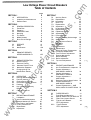
Table of Contents
7. 13
7. 14
7.1 5
Bell Alarm
7.1 1 .1 Operation
7.1 12 Adjustments
7.1 1 .3 Replacement
Electrical Control Component
7. 12.1 Component Replacement
7.1 2.2 F and G Switch
Adjustment
Drawout Mechanism
Buffer Assembly
7.14.1 Buffer Adjustment
Trip Latch Adjustment
SECTION 8
22
22
22
23
23
23
23
23
24
24
25
25
26
26
26
27
27
27
28
29
29
31
32
32
33
8.0
8.1
8.2
CONTACT MAINTENANCE
Arc Chute Removal & Inspection
Contact Adjustment -
33
33
15
AKA 30/30H & AKRU 30
34
8.3
Contact Adjustment -
16
16
17
17
8.4
18
18
8.7
13
15
15
18
18
18
19
20
20
21
22
22
8.5
8.6
AKA 50/SOH & AKRU 50
Contact Adjustment AKRT 50/SOH
Stationary Contact Identification
Contact Replacement AKA 30130H & AKRU 30
Contact Replacement - AKA
50150H, AKRU 50 & AKRT 50150H
SECTION 9
9.0
9.1
9.2
9.3
36
37
38
39
39
41
FUSED BREAKER
Fuse Sizes and Mounting
41
41
Special 2500 A Fuse For AKRU 50 41
Open Fuse Lockout Device
9.3.1 TypeA and B Breaker
OFLO Adjustment
9.3.2 TypeD Breaker
OFLO Adjustment
43
43
43
Page
10.3
10.4
SST Cabling Diagrams
1 0.5
SECTION 11
1 1 .1
1 3.5
1 3.6
1 4.0
ar
58
58
58
58
59
60
63
64
64
65
EC TRIP DEVICE
Series Overcurrent
Tripping Device EC-2A
1 3.1 1 Long Time-Delay And
High Set Instantaneous
Tripping
13.1.2 Instantaneous
Low-Set Tripping
1 3.1.3 Instantaneous
High-Set Tripping
70
70
72
72
72
72
72
w
Series Overcurrent
Tripping Device EC-1
73
Tripping
1 3.2.3 Instantaneous
Tripping
1 3.2.4 EC-1 Adjustments
Positive Trip Adjustments
Reverse Current Tripping
Device
1 3.4.1 Adjustments
1 3.4.2 Replacement
Switchette Feature
Trip Device Replacement
SECTION 1 4
lP
.E
lec
SECTION 13
13.2
58
Equipped with Ground Fault
65
MicroVersaTrip Cabling Diagrams 66
12.5
13.0
13.1
1 3.3
1 3.4
53
53
ca
1 2.3
12.4
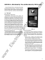
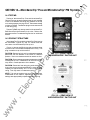
MICROVERSATRIP TRIP DEVICE
Programmer Unit
1 2.1.1 Fault Trip Indicators
1 2.1.2 Remote Fault Indication
1 2. 1 .3 Mi croVersaTrip Installation
Current Sensors
12.2.1 Replacement of Current
Sensors
Flux Shifter Trip Device
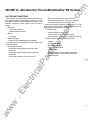
Troubleshooting
12.4.1 Resistance Valves
12.4.2 False Tripping-Breakers
tri
12.2
51
52
52
57
SECTION 12
12.0
12.1
48
48
56
Page
73
1 3.2.2 Long Time-Delay
56
TYPE ECS OVERCURRENT
TRIP DEVICE
ECS Cabling Diagrams
1 1.0
45
46
tM
10.1
10.2
1 3.2.1 Short Time-Delay
Tripping
45
an
TYPE SST OVERCURRENT
TRIP DEVICE
Programmer Unit
Current Sensors
1 0.2.1 Replacement of Current
Sensors
Flux Shift Trip Device
Troubleshooting
1 0.4.1 SST Test Set
1 0.4.2 Resistance Valve
1 0.4.3 False Tripping-Breakers
Equipped with Ground Fault
1 0.0
SECTION 13
45
ua
ls
SECTION 10
.c
om
f
ww
"
73
74
74
74
75
76
76
76
76
77
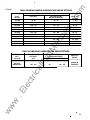
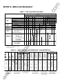
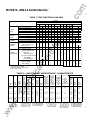
ELECTRICAL CHARACTERISTICS
Table 1 6
Charging and Closing
Operating Currents
Fuse Selection
77
77
Table 1 7
77
Bell Alarm Contact Rating
Table 1 8
Auxiliary Switch Contact Sequence
Table 1 9
Auxiliary Switch Contact Ratings
Table 20
Charging Times
Table 21
Shunt Trip
Undervoltage Device
Table 22
Coil Resistance
Table 23
Instantaneous Undervoltage
Device Settings
Table 24
Time-Delay Undervoltage
Device Ratings
77
77
77
78
78
79
79
.c
om
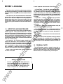
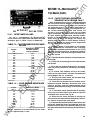
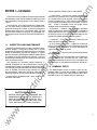
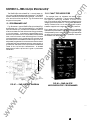
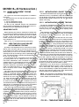
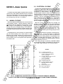
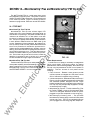
SECTION 1-lntroduction
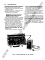
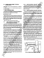
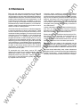
A basic inspection should consist of the following:
The proper use, care, and maintenance of these break
ers is a prime safety consideration for the protection of
personnel, as well as a means of minimizing equipment
damage when faults occur. Persons who apply, use, and
service these breakers will acquire the knowledge they
need by gaining the information contained in these instruc
tions.
a. Visual Check - Look for dirt, grease or other forei
material on any breaker parts. Check insulating surfac
for conditions that could degrade insulating properties
(cracks, overheating, etc.). Also check for loose hardware
and components on the breaker and the compartment's
bottom, loose or damaged control wiring and similar prob
lem areas.
b. Operation - Observe a few close-open operations
using the operating or maintenance handle. If a breaker is
seldom operated such that it remains open or closed for a
period of six months or more, it is recommended that ar
rangements be made to open and close it several times in
succession.
ua
ls
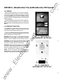
These instructions provide the maintenance procedures
and describe the operation of the 800 thru 2000 amp frame
size type AKA low voltage power circuit breakers listed in
Table 1 .
'
1.1
INSPECTIO N AND MAINTENANCE
d. Arc Chutes and Contacts - Inspect the condition of
the arc chutes and contacts. Look for excessive burning or
breakage. Check the amount of contact depression or
wipe.
tM
Breakers should be cared for under a systematic main
tenance program. Taking each breaker out of service
periodically for inspection and maintenance is an excellent
means of establishing high service reliability. It is good
policy to have one or more spare breakers to install in place
of breakers requiring maintenance. Keeping a stock of
recommended renewal parts will insure that maintenance
work can be done quickly.
an
c. Interlocks- During the Operational check verify the
safety interlocks are properly working.
e. Accessories- Verify that the various accessories are
working properly.
ar
f. The performance of the solid-state current trip devices
may be checked with a suitable test set. Check elec
tromechanical devices for positive trip in accordance with
the instructions in their Maintenance Manual, GEl 86157.
ca
lP
How frequently an individual breaker should be in
spected will depend on the circumstances of its use. It
would be well to inspect any breaker at least once a year. If
it is frequently operated, operated under severe load condi
tions, or mstalled in an area of high humidity or a dusty,
dirty atmosphere, inspections should be more often. In
spections might be monthly under adverse conditions.
lec
tri
Always mspect the breaker after a short-circuit current
has been mterrupted.
SAFETY PRECAUTION
ww
w
.E
BEFORE INSPECTING OR BEGINNING ANY
MAINTENANCE WORK ON THE BREAKER. IT
MUST BE DISCONNECTED FROM ALL VOLT·
AGE SOURCES. BOTH POWER AND CON·
TROL. AND BE IN THE ··oPEN' POSITION
4
1 .2
RENEWAL PARTS
The AKA breakers contain a variety of parts and as
semblies. Many of these are available as replacement
parts when the need arises. See publication GEF 4527,
Renewal Parts, for a complete listing of these parts.
-
.c
om
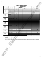
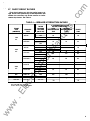
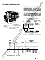
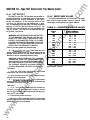
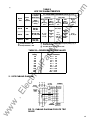
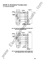
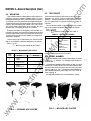
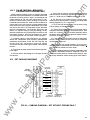
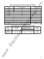
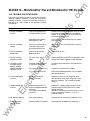
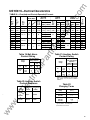
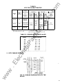
TABLE 1 BREAKER MODELS
2000
DC
800
1600
SOH
SOH
SOH
SOH
X
X
X
X
AKRT-(•)A 50, SOH
AKRT-(•)8 50, SOH
AKRT-(•)D 50, SOH
AKRT-(•)S 50, SOH
X
AKR-2A 30
AKR-28 30
AKR-20 30
AKR-2S 30
X
AKR-2A-50
AKR-28-50
AKR-20-50
AKR-28-50
X
AKRU-(*)A 30
AKRU-(*)8 30
AKRU-(*)0 30
X
AKRU-(*)A 50
AKRU-( *)B 50
AKRU-(")0 50
X
X
X
X
X
X
X
X
X
X
Th•s dlg•t ldenbf•es the tnp dev�ce type
X
X
ua
ls
X
X
as
X
X
X
X
X
X
X
X
X
X
X
X
X
X
X
X
X
X
X
X
X
X
X
folows
l
:
2 - EC (DC only)
4 - ECS
5 - SST
50/60 Hertz Only
6 - M•croVersa Tnp
N - Non-automabc. In adell bon, all non-automabc 250VDCbreaker types carry the suffix letter Dafter the frame number, e.g. AKR-NB-500
tri
-
X
X
X
X
X
}
ww
w
.E
lec
(*)
AKR-(•)A 50,
AKR-(•)8 50,
AKR·(•)D 50,
AKR-(•)S 50,
X
an
800
DC
X
tM
2000
AC
AKR-(•)A 30, 30H
AKR-(•)8 30, 30H
AKR-(•)D 30, 30H
AKR-(•)S 30, 30H
I,
ar
1 600
AC
AK�
lP
800
AC
BREAKER
DESIGNATION
ca
FRAME SIZE
(AMPERES)
MOUNTING TYPE
DRAWOUT
SUB·
DEEP
FUSED
STRUCTURE STATIONARY ESCUTCHEON BREAKER
AKD-8
5
.c
om
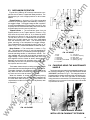
SECTION 2-General Description
ua
ls
Type AKR low-voltage power circuit breakers are used
for controlling and protecting power circuits in the low
voltage range (usually up to 600 volts). In serving this
function, they are a means of safely switching loads and
automatically clearing circuits when abnormal conditions
occur. Among these conditions, the more common are
short circuits and sustained overloads and under voltages.
The type AKR breakers are of the "quick-make, quick·
break description, having the feature of storing energy in a
closing spring for quick release in closing. In closing, some
energy is transferred to an opening spring to be used
subsequently for fast tripping.
an
Knowledge of how the breaker is designed and how it
operates will enable the owner to make proper use of the
breaker and to avoid mistakes in Its operation. Specific
directions on adjustments and maintenance procedures
will be treated later.
tM
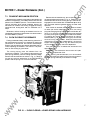
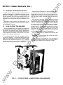
The three main functional components of a breaker are
its mechanism, an assembly comprising the conductive
members, and the interrupter.
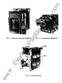
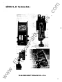
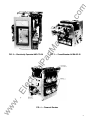
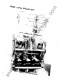
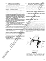
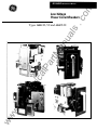
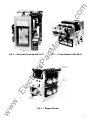
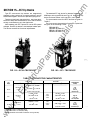
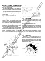
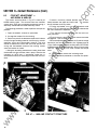
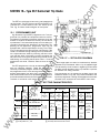
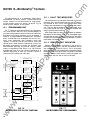
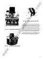
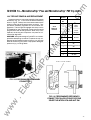
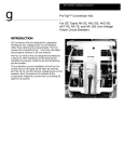
FIG. 1
-
Manually Operated AKR-4A-50-1
ar
The mechanism unit is designed to receive energy, store
it, and later (when called upon to do so) deliver it to close
the breaker's contacts. It must be able to reverse its com
mitment to close the breaker at any point upon the activa
tion of an automatic trip device (i.e., be "Trip-Free"). Fi·
nally, it also must be able to trip open a closed breaker
quickly enough to minimize arc erosion and in such a
manner as to effect proper arc transfer to the arc runner.
lP
These values represent the maximum continuous cur
rent capability of the respective frames. However, each
breaker carries a specific rating which is determined by the
current sensor ampere rating or top setting of the trip
device with which it is equipped.
tri
ca
The current-carrying members of the breaker are as·
sembled on the back frame, which provides the mechani
cal support required and also the insulating structure
needed. The conductive members are the studs for exter
nal connections, movable and stationary contact sets,
pivots for the movable contacts, and provision for mounting
the current transformers.
lec
The interrupter components are, in addition to the arcing
contacts, the arc runners mounted on the back base and
the removable arc quencher assemblies.
2.1
.E
In addit1on to these basic components, a breaker may be
equipped with any combination of many accessones and
interlockmg dev1ces. Breakers may also d1ffer m a vanety
of areas as shown in Table 1 . A bnef descnpllon of these
areas is g1ven below.
FRAME SIZE
w
ww
6
-
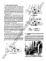
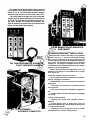
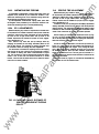
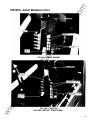
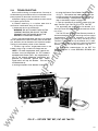
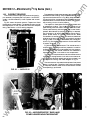
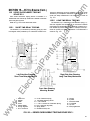
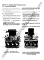
OPERATION
There are Manual and Electrical breaker models. The
Manual breaker, shown in Fig. 1 , has an operating handle
which is used to manually charge the mechanism closing
spring.
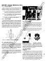
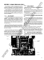
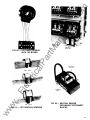
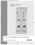
The Electric breaker, shown in Fig. 2, contains an elec
tric motor which charges the mechanism closing spring.
External control power is required to energize this motor
and its control c�rcuit. A nameplate md1cates what voltage
IS required by the motor circuit.
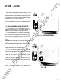
2.3
The breakers are ava1lable 1n 5 frame s1zes
800 am
peres A.C. (AKA 30'30H, AKAU 30). 1 600 amperes A.C.
(AKA SO:SOH, AKAU 50), 2000 amperes AC (AKAT
50/SOH). 800 amperes D.C. (AKA 30) and 2000 amperes
D.C. (AKA 50).
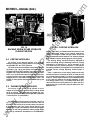
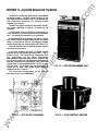
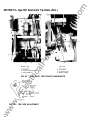
2.2
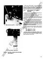
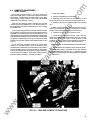
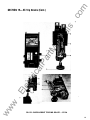
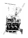
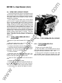
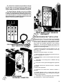
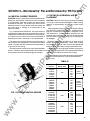
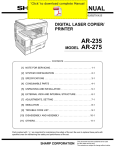
FUSED/NON FUSED
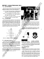
Fused breakers are identified as either AKRU 3 0 (800
ampere frame SIZe) or AKRU 50 (1 600 ampere frame size).
A fused breaker IS shown in Fig. 3. They are not inter·
changeable with Non-Fused breakers, since they require
deeper compartments for their fuses.
.c
om
ua
ls
r
tM
an
r···
FIG. 3
-
Fused Breaker AKRU-60-30
w
.E
lec
tri
ca
lP
ar
FIG. 2 - Electrically Operated AKR-SB-30
ww
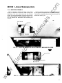
-
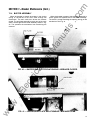
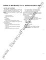
FIG. 4
-
Drawout Breaker
7
.c
om
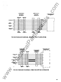
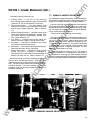
SECTION 2-General Description {Cont.)
2.5
MOUNTING
Type AKA breakers are designed for either drawout or
stationary mounting. Drawout breakers (See Fig. 4) are
equipped with features which make them easy to install in
or withdraw from their associated switchgear equipment.
These features are a racking mechanism (which facilitates
inserting and withdrawing the breaker unit) and primary
and control power disconnects which connect and part
automatically. Interlocking devices are included.
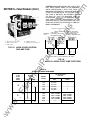
There are 4 types of solid-state, direct-acting, self
powered trip device systems associated with AKA break
ers. These systems are for AC applications only. For DC
applications an electro-mechanical system is available.
The trip device system is identified by the first middle
digit in the breaker's nameplate designation as follows:
AKA-(! )B-30
L- Trip device code number per Table 3
Stationary breakers are designed to be mounted on a
framework or panel, with mechanical fasteners being used
to secure the breaker frame and make power connections.
If control power connections are needed, a suitable termi
nal board is supplied.
TABLE 3
CODE
NUMBER
2
3
4
5
6
A
AKD-5
AKD-6
B
Substructure
D
AKD-8
-
-
ca
Substructure
s
Stationary
-
AC
AC
AC
AC
2.6
MODEL N U MBER
ar
Breaker Type
DC
EC
Power Sensor'
ECS
SST
MicroVersa Trip
'Power Sensor devices are discontinued. See publications
GEK-7309 and GEK-7301 for detailed servicing procedures
MOUNTING TYPE CODES
Drawout
APPLICATION
Type AKA breakers (see Table 2) exist as either no model
number of "-1" versions. For example AKA-5A-30H or
AKA-5A-30H-1.
lP
Code
TRIP
DEVICE
tM
AKA-5 (�0
Mounting type code letter per Table 2
Letter
TRIP DEVICE CODES
an
The mounting type is identified by the second middle
digit in the breaker's nameplate designation as follows:
TABLE 2
TRIP DEVICE
ua
ls
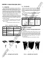
2.4
'
X
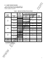
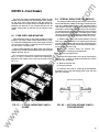
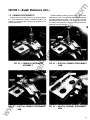
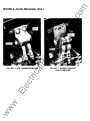
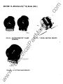
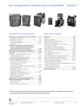
All AKRTSOH breakers use only molded arc chutes.
lec
tri
--
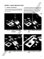
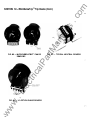
The difference between these models is their arc chute
construction. The arc chutes in the no model number break
ers have a two piece porcelain frame and use 2 arc chute
retainers, see Fig. 5. The "-1" breaker arc chutes have a one
piece molded polyester glass frame and 1 arc chute re
tainer, see Fig. 6.
i
ww
w
.E
.J
FIG. 5
8
•
-
-I
"1
1ct s !413-lirl
-
CERAMIC ARC CHUTES
..
.__.: _ _
;.,r ..
.......__
I er-:3 ..4 II t,q PI
;""·���·
.!.
___
FIG. 6 - MOLDED ARC CHUTES
-
.c
om
j
2.7
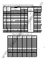
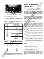
SHORT CIRCUIT RATINGS
Short circuit ratings vary with the applied system vol
tage. On 240 VAC systems they are also dependent upon
whether the overcurrent trip device contains an instan
taneous trip element. See Table 4.
TABLE 4 - BREAKER INTERRUPTION RATINGS
800
AC
AKA 30H
635
508
254
635
508
254
635
508
254
AKA 50
1600
AC
AKAT 50
635
508
254
635
508
254
ca
2000
AC
lP
AKA SOH-1
AKAT SOH
AKA 50
30
42
42
42
42
50
65
50
42
50
50
50
50
65
65
65
65
65
65
50
65
50
65
50
65
65
65
65
600
600
300VDC
200
200
-
300 VDC
25'
so•
3
25
50
lec
2000 DC
AKAU 30
AKAU 50
AKA 30
tri
800
1600
800 DC
SHORT
TIME
30
30
42
ar
AKA SOH
ua
ls
635
508
254
635
508
254
AKA 30
KA RMS SYMMETRICAL
WITHOUT
WITH
INSTANTANEOUS INSTANTANEOUS
TRIP
TRIP
an
BREAKER
TYPE
3c/> INTERRUPTION RATING
tM
FRAME
SIZE
(AMPERES)
RATED
MAXIMUM
VOLTAGE
(60HZ AC)
ww
w
.E
'With 40-800 Amp Trip Coils
'With 200-2000 Amp Trip Coils
>consult Factory For Application Data
9
.c
om
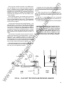
SECTION 3-Storage
The rejection hardware prevents the converse bf a.
thru d. above.
It is recommended that the breaker be put into service
immediately in its permanent location. If this is not possi
ble, the following precautions must be taken to insure the
proper storage of the breaker:
A detailed description of the rejection pin and bracket
combinations used is given in Installation manual, GEl
86150.
lP
an
ar
CAUTION: IF THE BREAKER IS STORED FOR
ANY LENGTH OF TIME, IT SHOULD BE INSPECTED
PERIOD/CALLY TO SEE THA T RUSTING HAS NOT
S TAR TED AND TO ASSURE GOOD MECHANICAL
CONDITION. SHOULD THE BREAKER BE S TORED
UNDER UNFAVORABLE A TMOSPHERIC CONDI
TIONS, IT SHOULD BE CLEANED AND DRIED OUT
BEFORE BEING PLACED IN SERVICE.
tM
2. The breaker should be stored in a clean location free
from corrosive gases or fumes. Particular care should be
taken to protect the equipment from moisture and cement
dust, as this combination has a very corrosive effect on
many parts.
ua
ls
1. The breaker should be carefully protected against
condensation, preferably by storing it in a warm dry room,
since water absorption has an adverse effect on the insula
tion parts. Circuit breakers for outdoor switchgear should
be stored in the equipment only when power is available
and the heaters are in operation to prevent condensation.
ca
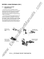
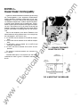
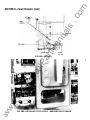
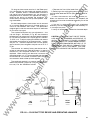
SECTION 4-
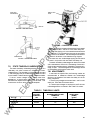
FIG. 7- DRAWOUT BREAKER
REJECTION SYSTEM
Drawout Breaker Interchangeability
FRONT OF
COMPARTMENT
lec
tri
In general, drawout breakers of the same type an d r ating
are interchangeable in their equipment compartments:
drawout breakers of different frame sazes are not anter
changeable. To prevent inserting the wrong type breaker
into a drawout compartment. suitable "reJectaon hardware"
is affixed to each breaker and ats compartment. Fagure 7
shows a typacal re1ectaon bracket whtch ahgns wath a reJec·
lion pan tn the drawout rail (Fag. 8) When the wrong type
breaker as tnserted anto a compartment the bracket and ptn
do not mate. preventang the breaker from seattng atself tnlo
.E
the drawout ratls.
There as one exception to the above Breakers of the
same frame s•ze havtng dafferent short carcu•t ratangs may
be interchanged •n one darechon only
RIGHT
SIDE
PIN
a. An AKR-30H can be anserted tnto an AKR-30 compart·
w
ment.
b. An AKR·SOH can be anserted tnto an AKR-50 compart·
ww
ment.
c. An AKR·SOH-1 can be anserted tnto an AKR-50 and
AKR·SOH compartment.
d. An AKRT·SOH can be anserted anto an AKRT-50 com
partment.
10
FIG. 8 INSERTING THE BREAKER
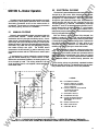
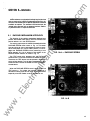
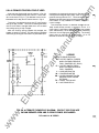
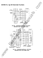
5.2
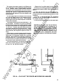
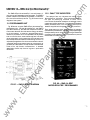
SECTION 5-Breaker Operation
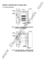
ELECTRICAL CLOSING
On electrically operated breakers the closing springs are
charged by a gear motor. With the springs discharged,
voltage applied to the control circuit will energize the motor
through the G switch contacts- see Fig. 9. The motor,
through the gear reduction output crank, compresses the
closing springs until they are fully charged. As this fully
charged position is reached, mechanically operated
switches "F" and G reverse their shown position, the G
switch deenergizing the motor and the "F" switch estab
lishing a circuit to the "X" relay. At the same time, a
mechanical prop is positioned to prevent the discharge of
the fully charged closing spring.
"
A breaker may be equipped to operate either manually
or electrically. Both types of operation result in the same
fast-closing movement as far as the contact action is
concerned. The variation is in the way energy is stored in
the closing spring, and how it is released.
"
"
"
"
"
ua
ls
5.1
.c
om
'
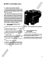
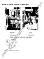
MANUAL CLOSING
Manually operated AKA breakers are constructed with
front-mounted handles. Handle operation resets the
mechanism and fully charges the closing spring. A com
plete charge is accomplished in either cranking the han
dle through one cycle (1 35-degree swing) or three cycles
(50-degree swing). Manually operated breakers manufac
tured after July, 1984 can only be charged by cranking
the handle through one cycle.
The CLOSE button
mounted on the escutcheon, is used to manually close
the breaker contacts and the TRIP button is used to open
them.
an
With the closing spring propped fully-charged, the
breaker is ready for closing. This may be accomplished
electrically by depressing the closing switch on the breaker
(if so equipped) or by a remote closing switch. Operation of
the closing switch energizes the "X" relay, which in turn
energizes the closing solenoid. This removes the prop,
releasing the closing springs to close the breaker.
tM
As the closing relay is energized, it energizes anti-pump
relay "W". If the closing switch is maintained closed, the
anti-pump relay will remain picked-up to prevent a second
closing operation on the breaker in the event it is tripped
open automatically. The closing impulse must be released
and reapplied before a second closing operation can
occur.
lec
�r
'I
X
cc
w
CC- CLOSING SOLENOID
�
F- CUTOFF SWITCH.
cc
X
.E
Gl
...J
ww
LEGEND
tri
CONTROL
SOURCE
-
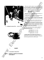
The closing springs on electrically operated breakers
can be manually charged. The breakers can also be man
ually closed. Refer to Section 5.4 for this procedure.
ca
lP
ar
I f equipped with a closing solenoid, a manual breaker
may be closed remotely by a control switch or relay.
Before this can be done, however, the closing spring has
to be charged by hand. The closing solenoid is an op
tional accessory and is not supplied unless specified in
the breaker order.
w
TC
�
--------- -- ---
CLOSED
WHEN CLOSING SPRING IS
FULLY CHARGED.
G- CUTOFF SWITCH OPEN WHEN
CLOSING SPRING IS
FULLY CHARGE D
L - AUXILIARY SWITCH
M - CHARGING MOTOR
PB- CLOSE PUSHBUTION ON
BREAKER ESCUTHEON.
OPTIONAL
TC- SHUNT TRIP DEVICE
W - ANTI-PUMP RE LAY
X- CONTROL RE LAY
-
FIG. 9 - ELEMENTARY DIAGRAM FOR ELECTRICALLY OPERATED DRAWOUT BREAKER.
CONTACT POSITIONS ARE SHOWN WITH BREAKER OPEN AND CLOSING SPRINGS DISCHARGED.
11
.c
om
'
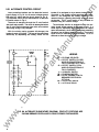
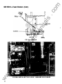
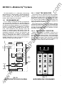
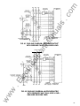
5.2.1 ALTERNATE CONTROL CIRCUIT
The motor is energized through the 'G' cutoff switch
and the K-relay contact. The motor is deenergized when
the 'G' cutoff switch changes state which occurs when
the closing spring is fully charged.
tM
REMOTE
CLOSE
-1 �-.,
A
F- CUTOFF SWITCH, CLOSED
WH EN CLOSING SPRING IS
FULLY CHARGED (D.C. ONLY)
TC
G - CUTOFF SWITCH, OPEN
WHEN CLOSING SPRING IS
FULLY CHARGED.
L- AUXILIARY SWITCH
M - CHARGING MOTOR
PB- CLOSE PUSHBUTTON ON
BREAKER ESCUTCHEON.
OPTIONAL
TC - SHUNT TRIP DEVICE
K - ANTI-PUMP RELAY
.E
lec
tri
ca
lP
t�PS
LEGEN D
CC - CLOSING SOLENOID
ar
o------o- -
The anti-pump function is obtained through the nor
mally closed K-relay contact in the motor circuit. If a
close signal is maintained after the breaker has tripped
open automatically, the K-relay Is energized preventing
the motor from charging the closing spring. The closing
signal must be removed for approximately 1 .3 to 2.0
seconds to allow the closing spring to charge.
an
With the closing spring propped fully-charged, the
breaker is ready for closing. This may be accomplished
electrically by depressing the closing switch on the
breaker (if so equipped) or by a remote closing switch.
Operation of the closing switch energizes the K-relay
which in turn energizes the closing solenoid.
Thi�
removes the prop, releasing the closing springs to close
the breaker. The 'F' cutoff switch is only installed on
breakers using D.C. control voltage.
ua
ls
Later production breakers use the electrical control
circuit shown in Fig. 9A for all control voltages except
250 volts D.C. which uses the circuit shown in Fig. 9.
This alternate control circuit eliminates the X-relay and
CC switch shown in Fig. 9.
ww
w
FIG. 9A. ALTERNATE ELEMENTARY DIAGRAM. CONTACT POSITIONS ARE
SHOWN BREAKER OPEN AND CLOSING SPRINGS DISCHARGED.
12
'
.c
om
!
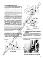
5. 3
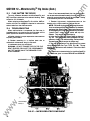
M ECAHNISM OPERATION
Figure 10 shows the mechanism components in the
Closed, Tripped and Reset positions. The closing spring
is shown in the charged position in all of these details.
lP
ar
tM
Reset Position - The mechanism is shown in Fig.
10C. The cam, item no. 3, which is assembled to the cam
shaft, item no. 4, is rotated by the charging motor,
manual operating handle, or maintenance handle. The
cam engages the cam roller and partially extends the
toggle linkage. This allows the secondary latch to pivot
against the front frame as shown leaving a gap between
the trip latch and secondary latch roller. The secondary
latch is now in a position to engage with both the top
latch and cam roller.
10 11
ca
The breaker closes when the closing spring
discharges and rotates the cam against the cam roller.
The toggle linkage is fully extended, pivoting the secon
dary latch from the front frame and engaging it with the
trip latch and cam roller as shown in Fig. 10A.
5
5.4
FIG.10C RESET
Prop
Cam
4. Camshaft
5. Cam Roller
10. Trip Shaft
2.
3.
Trip Latch
Insulated Coupling
Main Shaft
14. Secondary Latch
15. Opening Spring
11.
12.
13.
CHARGING USING THE MAINTENANCE
HANDLE
The closing spring on electrically operated breakers can
be manually charged by using the maintenance handle
(568B386G1) as shown in Fig. 11. The triangular socket in
the maintenance handle mates with the mechanism's
camshaft extension on the front right side of the breaker.
Using the knob on the handle, it will probably be necessary
to a lign this socket to fit on the end of the shaft.
.E
lec
w
8.
tri
When the breaker is closed and the closing spring
discharged, the upper cam roller is supported by the cam
rather than the prop. This is the position the mechanism
must be in to check contact adjustment refer to Sectior
14
FIG. 108 TRIPPED
an
Tripped Position - The mechanism goes from the
Closed position to the Tripped position, shown in Fig.
108, when the trip shaft, item no.10, is rotated by either
the manual trip button or one of the other trip devices.
The trip latch, item no.11 is assembled to the trip shaft.
When the trip shaft rotates, the trip latch disengages
from the secondary latch roller. The secondary latch
pivots, resulting in the collapse of the toggle linkage.
This collapse along with the opening spring, item no.15,
causes the breaker contacts to open.
ua
ls
Closed Position- As shown in Fig.10A, the movable
contacts are held against the stationary contacts by the
toggle linkage. The toggle linkage is held in position
through the engagement of its cam rollers, item no. 5,
with the prop, item no. 2 and the secondary latch/trip
latch, item nos. 14 & 11.
ww
.
AG. 10A CLOSED
FIG. 1 1- MAINTENANCE HAN DLE
INSTALLED ON CAMSHAFT EXTEN SION
13
.c
om
,
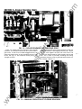
FIG. 1 2
-
tM
an
ua
ls
SECTION 5-Breaker Operation {Cont.}
ROLLER ENGAGED WITH CLOSING PROP
lP
ca
tri
lec
.E
w
ww
14
(�i:)
El £
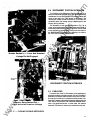
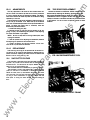
Rotate the camshaft using the maintenance handle until
the ratchet assembly's roller engages with the prop. Do not
drive the roller against the prop with undo force. The
breaker can now be closed by removing the prop from thr #"
roller. This is done by manually activating the closin�
solenoid's armature. Push the solenoid's armature into its
windings. See Fig. 13.
ar
There is a ratchet assembly attached to the camshaft
extension. This ratchet is normally driven by the breaker's
gear motor. A roller on this ratchet engages with a prop
when the closing spring is fully charged and driven over
center, see Fig. 1 2. This holds the closing spring in a
charged condition.
G f N ERA L
FIG. 1 3 - MANUAL OPERATION OF CLOSING SOLENOID
.
.c
om
'
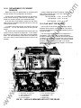
SECTION 6-lnterlocks
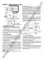
RACKING MECHANISM I NTERLOCK
The function of the racking mechanism interlock is to
prevent the breaker from moving from its CONNECTED
position before it is in the OPEN position.
tM
The racking mechanism drive shaft is located behind the
RACKING SCREW cover shown in Fig. 14. This cover
must be slid to the right to gain access to the drive shaft.
When the breaker is in the CLOSED position, a link en
gages the RACKING SCREW cover preventing it from
being opened. This link is driven by the motion of the
OPEN/CLOSED indicator as shown in Fig. 15.
an
6.1
ua
ls
AKA breakers are equipped with safety interlock devices
that are required by Industry Standards and Certifying Au
thorities. Interlock devices for special applications are also
available as options. The standard interlock devices de
scribed below are used only on drawout breakers. Station
ary breakers have no required interlocks.
ar
FIG. 1 4-A - RACKING SCREW
ca
lP
The TRIP button also engages with the RACKING
SCREW cover in both the OPEN and CLOSED positions.
Therefore, the TRIP button must be pushed in before the
cover can be opened. This will open the breaker if it was
closed and also remove the OPEN/CLOSED linkage dis
cussed above.
When the RACKING SCREW cover is open it holds the
TRIP button in. This keeps the breaker tri p free so a
mechanism closing cycle will not cause contact movement
especially when the breaker is being racked in or out.
FIG. 14-B
ww
w
.E
lec
tri
-
15
.c
om
.
tM
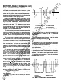
position, the crank's pin reaches the end of the slot in the
linkage. Continued motion of the racking mechanism
causes the linkage to rotate the lever which moves the
closing solenoid armature forward. The armature linkage
then releases the prop, discharging the closing spring.
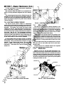
POSITIVE INTERLOCK
The Closing Spring interlock should be adjusted to
cause the closing spring to discharge when the racking
mechanism is a minimum of 1 and a maximum of 2Y2
turns short of the fully racked out position. In this position
the racking handle can no longer be turned. If adjustment is
required, use the linkage adjusting screws shown in
Fig. 17.
lP
6.2
FIG. 1 6 - POSITIVE INTERLOCK
ar
FIG. 1 5
RACKING SCREW COVER INTERLOCK
C LOSED POSITION
an
ua
ls
SECTION 6-lnterlocks (Cont.)
The function of the positive interlock is to keep the
breaker trip-free while it is being racked in or out between
the CONNECTED and TEST positions.
6.3
lec
tri
ca
The positive interlock is located on the breaker's left side
as shown in Fig. 16. As the breaker moves between the
CONNECTED and TEST positions, the positive interlock
engages with a ramp cam located in the breaker compart
ment. Th1s cam raises the interlock's lever assembly caus
ing the trip shaft to move and preventing the trip latch from
engaging with the secondary latch assembly roller. The
breaker IS held trip-free and cannot be closed during this
interval.
CLOSING SPRING INTER LOCK
.E
The function of the clos1ng sprrng interlock is to dis
charge the clos1ng sprrng as the breaker IS being racked
out of 1ts hous1ng Th1s ehm1nates the hazard of a com
pletely charged breaker be1ng discharged after the breaker
is removed from 1ts compartment
ww
w
The operat1on of the clos1ng sprrng 1nterlock IS shown m
Fig. 17. The rack1ng mechan1sm arms and the crank are
connected to a common shaft. As the breaker rs racked out
a pin anached to the crank moves through the slot rn the
linkage. The hnkage IS connected to a lever wh1ch engages
with a prn on the clos1ng solenoid armature hnkage. When
the rack1ng mechantsm approaches the DISCONNECT
16
Note - undue force on the racking handle at the fully
racked out position will cause the lever to move past the
pin on the armature linkage. This will bind u p the overall
interlock. Under these cond itions, continued application
of this force will deform the linkage assembly. A later
lever design (shown in Fig. 17) includes a stop which pre
vents the lever from moving past the pin. When the pin is
against this stop, undue force may still d eform the link
age assembly.
.
.c
om
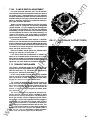
6.4
DISCONNECT POSITION I NTERLOCK
The function of the Disconnect Position Interlock is to
block the RACKING SCREW cover open when the racking
mechanism is in the DISCONNECTED position. When the
cover is held open, the TRIP button is depressed. The
mechanism is held trip-free and there is no contact arm
movement when the closing spring is discharged by the
Closing Spring interlock.
tM
an
ua
ls
The operation of this interlock is shown in Fig. 18. A
crank, which is attached to the racking mechanism shaft, is
connected to the blocking plate through a link. As the shaft
turns, the blocking plate rotates; holding the cover open in
the DISCONNECTED position, but allowing it to close in
the TEST and CONNECTED positions.
.E
lec
tri
ca
lP
Linkage Pin Not Engaged
ar
Breaker Racked In - Lever And Armature
w
Breaker Being Racked Out -
ww
Lever Activates Armature Linkage
FIG. 17
-
FIG. 1 8 DISCONNECT POSITION INTERLOCK
6.5
PADLOCKS
Provisions are made in all breakers to use padlocks to
prevent the breaker from being closed. For non Type B or D
breakers the padlock shackle goes through the TRIP but
ton hole and out the slot in the side of the escutcheon. For
Type B or D breakers the padlock shackle goes through the
TRIP button hole and out the RACKING SCREW cover
hole in the deep escutcheon. In either case, the shackle
holds the TRIP button in keeping the mechanism trip-free.
C LOSING SPR ING I NTERLOCK
17
.c
om
SECTION &-Interlocks (Cont.)
'
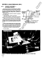
6.7 O PTIONAL INT ERLOCKS
The function of the Key Interlock is to prevent an open
breaker from being closed when the lock bolt is extended
and its key is removed.
The optional interlocks are key interlocks and door inter
locks. On drawout breakers, these devices are mounted in
the equipment and are part of the breaker enclosure. Pad
locks may be used to lock the "inner" house in the "discon
nected" position.
The operation of this interlock is shown in Fig. 19. When
the breaker is in the OPEN position, the end plate assembly
on the main shaft pivots the lever counter-clockwise. This
removes the pin on the lever from blocking the lock bolt.
Extending the lock bolt rotates the linkage which moves the
trip shaft, preventing the mechanism from closing the
breaker.
1. Lock
2. End Plate
tM
3. Pin
When the breaker is in the CLOSED position, the
flywheel assembly is away from the lever. The lever is
spring loaded and rotates clockwise causing its pin to block
the lock bolt extension.
an
B REAKER
ua
ls
6.6 KEY I NT ERLOCK-STAT IONARY
Lock Bolt
5. Pin
6. Lever
ca
lP
ar
4.
r?�r=�==�-4
-;.....J:J;�-..:..+---- 3
_,.;..�I---
lec
tri
�::::::-::-=....:.*
.:..::=::=-::
���
5
6
FIG. 1 9 - KEY INTERLOCK-STATIONARY B R EAKERS
.E
SECTION 7- Breaker Maintenance
SAFETY PRECAUTION
ww
w
WARNING: BEFORE INSPECTING OR BEGIN
NING ANY MAINTENA NCE WOR K ON THE
BREAKER, IT MUST BE DISCONNECTED FROM
ALL VOL TAGE SOURCES, BOTH POWER AND
CONTROL. AND THE BREAKER MUST BE IN THE
"OPEN" POSITION.
18
7.1
LU BRICATION
In general, the circuit breaker requires moderate
l ubrication. The majority of the factory l ubricated bear
ing points and sliding surfaces are accessible for inspec
tion and if necessary, cleaning and relubricating. The on
ly l ubricant used on the breaker for both electrical and
mechanical areas is General Electric specification
D50HD38 (Mobilgrease 28).
.
.c
om
'
SECTION 7 -Breaker Maintenance (Cont.)
7.2
3.
4.
5.
6.
There are two handle adjustment linkage designs in use.
The adjustment linkage connects the handle assembly to
the chain drive mechanism which turns the cam shaft. The
length of this linkage provides the handle adjustment.
If the link is too long, the handle stroke cannot extend the
closing spring enough for it to go over center. In this event,
use the maintenance handle to complete the spring charg
ing. The breaker can then be closed and opened prepara
tory to further shortening of the link.
If the link is too short, one-stroke charging is not possi
ble. However, more than one stroke will charge the
springs.
The original linkage design used a double-ended stud in
the linkage center. A hex section in this stud allowed adjust
ing with an open-end wrench. When looking down on the
breaker, turning the wrench clockwise lengthens the link.
The opposite motion shor:tens it. The range of adjustment
is 300 degrees. In the confined space available, each
wrench stroke imparts 1 5 degrees movement. The best
setting is approximately mid-range.
ar
7.
On manually-operated AKA breakers, the closing
springs may be charged either by a single 1 35 degree
clockwise handle stroke or up to four multiple strokes of
lesser swing. The following adjustment procedures should
be performed using the single-stroke method. By so doing,
proper multi-stroke operation is assured.
ua
ls
2.
Contacts - A thin fil m on the stationary and
movable contact assembly pivot surfaces. Refer to
Section 8.
Racking Mechanism - The drive threads, jamb
nut/trunnion interface, thrust washer/collar interface,
and the shaft support bearings. Refer to Section
7.13.
Manual Operating Handle - Lubricate the two pivot
areas associated with the adjustment linkage. Also,
the handle, mounting shaft/support bushing inter
face. Refer to Section 7.2.
Flux Shifter - Lubricate pivoting and sliding sur
faces of the reset linkage. Refer to Section 1 0.3.
Switchette - Lubricate the activator lever surface
that contacts the switchette button.
Mechanism - All accessible bearing and sliding sur
faces that have been factory lubricated.
Primary Disconnects - Lubricate the finger contact
surface just prior to installing in switchgear or
lubricate and then cover the disconnect assembly to
protect from dust, dirt, etc. Refer to Section 7.5
tM
1.
MANUAL HANDLE ADJUSTMENT
an
The areas requiring l ubrication are:
The present design is shown in Fig. 20. This linkage is
assembled together on a threaded stud. Adjustment is
accomplished by removing the upper linkage assembly
from the handle assembly and changing the linkage length
by turning the upper linkage up or down the threaded stud.
ww
w
.E
lec
tri
ca
lP
Before lubricating, remove any hardened grease or dirt
from the latch and bearing surfaces. After lubricating,
remove all excess lubricant of dirt·or dust. The use of
cotton waste to wipe bearing surfaces should be avoid
ed. The cotton ravelings may bec.ome entangled under
the bearing surfaces and destroy the surface of the bear
ing.
FIG . 20
-
MANUAL HANDLE ADJUSTMENT
19
.c
om
SECTION 7-Breaker Maintenance (Cont.)
Remember, before installing the breaker back into its
compartment, the drawout mechanism must be returned to
the DISCONNECT position.
7.4
SLOW CLOSING T H E B REAKER
Closing the breaker slowly, while observing the action of
the mechanism and contacts, is a good way of judging the
correctness of mechanical and contact relationships.
Some of the maintenance procedures described later will
involve operating the breaker in this manner. The proce
dure for slow closing is given below.
Remove the hex-head bolt only, do not remove or loosen
the slotted head screw shown in Fig. 21 . Removal of the
slotted head will cause the closing spring to become dis
engaged from the camshaft with considerable force. Verify
that this screw remains tightened during the slow close
operation.
ua
ls
Maintenance or inspection should be conducted with the
breaker on a workbench. The drawout mechanism must be
placed in the CONNECT position. This will deactivate the
various interlocks which would otherwise prevent the
mechanism or contacts from closing. Engage the racking
handle with the racking shaft and turn clockwise until it
stops.
After the bolt is removed, use the maintenance handle
to rotate the ratchet assembly's roller onto the closing
prop (see Charging Using The Maintenance Handle, sec
tion 5.4). At this point, the closing prop must be removed
by either pushing the CLOSE button on Manual breakers,
or pushing the closing solenoid armature on electric
breakers (see Fig. 1 3). When the closing prop is removed,
continue turning the camshaft. The contacts and
mechanism is in Its fully closed position, the cam will
support the cam roller (refer to Fig. 10 & section 5.3) and
the contacts will develop maximum depression.
an
D RAWOUT MECHANISM POSIT ION
Push the TRIP button to release the mechanism and
open the contacts.
CAUTION
The mechanism and contacts will open
with normal speed and force.
tM
7.3
-
When replacing the hex-head bolt, tum the camshaft
with the maintenance handle to align the mating holes in
the lower spring assembly and camshaft linkage.
ww
w
.E
lec
tri
ca
lP
ar
The closing spring must be isolated from the
mechanism's camshaft. This is done by disconnecting the
lower spring assembly from the mating camshaft linkage.
Remove the hex-head bolt as shown in Fig. 21 . Remove
this bolt only with the mechanism in the DISCHARGED
position and the spring at its minimum extension.
20
FIG. 21 - SLOW CLOSING-LOWER SPRING ASM HARDWAR E
.c
om
SECTION 7-Breaker Maintenance (Cont.)
7.5
P RIMARY DISCONNECTS
The BOO ampere breakers use four primary disconnect
fingers per phase. The 1 600 and 2000 ampere breakers
use eight fingers per phase. Fig. 22 shows a line and load
end disconnect assembly. The line end disconnects on
fusible breakers have the spring pointing downwards,
otherwise they are identical .
lP
ar
tM
an
ua
ls
Primary disconnects are found only on drawout break
ers. They provide the flexible connection between the
breaker's line and load terminals and the equipment's line
and load terminals.
FIG. 22 - P RI MARY DISCONNECT
w
.E
lec
tri
ca
ASSE M B LY
FIG. 23 - PARTIAL PRIMARY DISCONNECT
ASM
ww
FIG. 24
-
PARTIAL P R I MARY DISCONN ECT
ASM
FIG. 25- PARTIAL P R I MARY DISCONNECT
ASM
21
.c
om
SECTION 7-Breaker Maintenance (Cont.)
7.5.1
REPLACEMENT
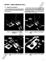
Figs. 22, 23, 24, and 25 show the primary disconnect
assembly breakdown. Refer to these illustrations when
replacing the disconnects. Note the following details:
ua
ls
Fig. 25- The position of the spacer in the breaker stud.
The hole in the spacer must be positioned as
shown so it will align with the holes in the clip.
Fig. 24 - The engagement of the fingers with the re
tainer. Also the location of the 'bowtie' spacers in
the fingers, both upper and lower.
Fig. 22 & 23 - The position of the upper and lower
retainers and, again, the 'bowtie' spacers.
ADJUSTMENT
7.6
an
FIG. 27
-
AUXILIARY SWITCH LINKAGE
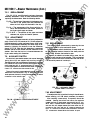
7.6.1 REPLACEMENT
The switch may be dismounted by removing the two
bolts which fasten it to the mechanism frame.
The replacement switch should have its crank shaft set
so that the arrow head on the end of the shaft points as
shown in Fig. 28 when the breaker is open.
If a switch is added to a breaker having none, the ad
justing link will also have to be installed. This is connected
to the pin on the crank which is attached to the main shaft.
It is secured by means of a cotter pin.
ar
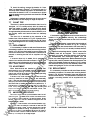
The primary disconnect assembly is factory adjusted to
apply a force of 85- 1 05 pounds on a 1/2 thick copper bar
inserted between the upper and lower fingers. After instal
lation of the disconnect assembly this force range is ob
tained by tightening the locknuts to set the dimension
shown in Fig. 26. Note that this dimension is measured
between the top of the retainer and the underside of the
washer. Also note that no bar is inserted between the
fingers when setting this dimension.
tM
7.5.2
AUX I LIARY SWITCH
lP
All electrically operated breakers and manual breakers
having shunt trips are supplied with auxiliary switches.
Depending upon the requirements of the breaker's applica
tion, the switch may contain from two to six stages. Usually,
each stage has one "'A" contact and one "B" contact. "A"
contacts are opened or closed as the breaker is opened or
closed. "B" contacts are the reverse of this.
ca
ARROWHEAD
tri
The auxiliary switch is mounted on the upper side of the
mechanism frame as shown in Fig. 27. A crank on the main
shaft operates the switch through an adjustable link which
connects it to the switch crank.
lec
!*
_l_
,J:;:L_
:_--::-::�;��
�:-J
11
i
-
�
�
J
_::_
-_
I
·: ___
--�
L
j
ww
w
FIG. 26 - PRIMARY FINGER ADJUSTMENT
22
AG. 28- AUXILIARY SWITCH
CRANK SHAFT POSITION
�- -----...
I
'-- �-�-·-r
'F' �"$:.I-:.. ..-�
'-=t� ?
.E
. \' ________...
7.6.2 ADJ USTMENT
If the adjustable link Is installed, its length should be set,
before installing. at 6 3J8 inches, between pin centers.
After installing a new switch, its operation should be
checked. Viewing the switch from above, the contacts
toward the front of the breaker are nonnally the "B" con
tacts. Even if a special switch is used, it is always the case
that the first two stages nearest the crank have the "B"
contacts to the front, and the "A" contacts towards the
back. ··A" contacts are closed when the breaker is closed.
"B"" contacts are closed when the breaker is open.
.c
om
:To check the setting, arrange the breaker for "slow
close" as described in Section 7.4. Through the use of a
continuity tester, observe the position of the breaker con
tacts when the switch's LI-LIC "A" contacts touch. At this
point the breaker's arcing contacts must be within .250 "•
� of closing.
Adjustment is made by disconnecting the upper end of
the adjustable link and varying its length as required.
The shunt trip device opens the breaker when its coil is
energized. An "A" auxiliary switch, which is closed only
when the breaker is closed, is in series with the device
coil. Connections are made to the external tripping source
through secondary disconnects on drawout breakers, or to
the auxiliary switch and terminal board on stationary
breakers.
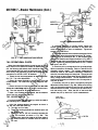
The shunt trip is mounted to the underside of the
breaker front frame as shown in Fig. 29. A second shunt
trip may also be mounted to the frame (see Fig. 30) if a se
cond undervoltage device isn't already installed, see Sec
tion 7.8.
FIG. 29 - SHUNT TRIP AND
UNDERVOLTAGE MOUNTING
If the breaker is disconnected, and for some reason the
breaker is to be operated manually, the undervoltage
device may be tied or wired down so that it will not cause
tripping.
The undervoltage device is mounted to the underside of
the breaker front frame as shown in Fig. 29. A second
undervoltage may also be mounted to the frame (see Fig.
31) if a second shunt trip isn't already installed, see Sec
tion 7.7.
tM
7.7.1 REPLACEMENT
ua
ls
S H U NT TRIP
an
7.7
If a second undervoltage device is added, a new buffer
assembly block will be supplied; This is required for
clearance, in this case, the buffer assembly must be taken
off, disassembled, and remounted together with the
number two undervoltage device. Before disassembling the
original buffer, carefully measure the distance between the
faces of the threaded members as shown in Fig. 31, and set
this dimension carefully on the new assembly. Refer to the
breaker wiring diagram for the coil lead connections.
ar
If it is necessary to replace or add one of these devices,
t he easiest procedure is to remove the mounting bracket,
shown in Fig. 29, from the breaker frame and remove the
device from the bracket. If a replacement or new device is
ordered, a mounting bracket will be supplied with the
device.
lP
If a second shunt trip is added, this is mounted by
means of an additional bracket as shown in Fig. 30. This
additional bracket is fastened by two of the hex head bolts
used to fasten the buffer assembly to the breaker frame.
ca
7.7.2 ADJUSTMENT
tri
When these devices are installed or replaced, their
positive ability to trip the breaker must be demonstrated.
This is done by placing a 1 /32·inch shim between the ar
mature and magnet of the device and manually operating
the armature to trip the breaker.
7.8
.E
lec
If the shunt trip is not successful in this test, check the
mounting fasteners to make sure they are reasonably
tight. If they are, then bend the trip paddle on the trip shaft
to slightly reduce the distance between the trip arm of the
device and the trip paddle, and recheck for positive trip. If
this bending is necessary, be careful that it is not over·
done. Verify that there is a .030 ··.® · gap between the ' ,
trip arm and t h e trip paddle with the breaker closed. This
gap is necessary to prevent nuisance tripping.
7.8.1 REPLACEM ENT
If it is necessary to replace or add one of these devices,
the easiest procedure is to remove the mounting bracket
shown in Fig. 29, from the breaker frame and remove the
device from the bracket. If a replacement or new device is
ordered, a mounting bracket will be supplied with the
device.
� (, 0
UN DERVOLTAG E DEVICE
w
The undervoltage deivce tnps the breaker when its coil
is de-energ tzed . The leads of the coil are connected direct
ly to secondary disconnects or to a terminal board. Under
normal conditions. the coil remams energized and the
breaker may be closed.
ww
" Drop-out" of the armature, with resultant breaker tripp.
ing, occurs when the voltage is reduced to less than 60
percent of the rated voltage. An open armature will render
the breaker incapable of closing. The armature "picks up"
and al lows c losing, if the voltage ts 85 percent or more of
its nominal value. Refer to Table 23. Section 14 for the ac·
tual drop out and pick up voltage ranges.
FIG. 30 - 2ND SHUNT TRIP INSTALLATION
23
.c
om
ua
ls
SECTION 7-Breaker Maintenance (Cont.)
an
FIG. 32A - UNDERVOLTAGE DEVICE
7.8.2 OPERATIONAL CH ECK
tM
ar
FIG. 31 - 2N D UN DERVOLTAGE DEVICE
If excessive clearance or binding exists, loosen the
screws holding the magnet assembly to the frame and
move the magnet up or down as necessary. Tighten the
screws to 27 to 32 in-lbs.
2. The air gap between the armature and magnet with the
undervoltage device de-energized should be .25 inches.
Check the gap by inserting a .201 ± .005 diameter gage
between the armature and magnet as shown in Fig. 328. If
necessary reset the air gap adjusting plate so that the gage
pin fits. Tighten the adjusting plate screw to 9 to 1 1 inches
and cover it with RTV.
3. Check the pick up voltage level with the undervoltage
device mounted on the breaker. Refer to Table 23 for the
allowable voltage ranges. The voltage measurements
should be made at the breaker's secondary d isconnects
and with the undervoltage coil energized. The coil should
also be close to room temperature (approx. 20-240C) when
taking voltage measurements. The coil resistance will in
crease as its temperature increases and will change the ac
tual pick up level.
If necessary, the pick up level is changed by using the
adjustment screw shown in Fig. 32A. Remove the locking
wire, tum the screw clockwise to raise the pick up level and
counterclockwise to lower. Once the pick up level is set, In
stall the locking wire. Allow t�-coil to cool and then
recheck the pick up level with 3 quick measurements.
ca
lP
When the undervoltage device is used as part of a shut
down circuit which opens the breaker by deenergizing the
coil, the following operational check should be made. It is
recommended that this check be performed every 12 mon
ths or every 1 7fiJ operations for AKR 30 breakers and 500
operations for AKR fiJ I AKRT fiJ breakers.
tri
1 . Check the trip latch engagement as described in Sec·
tion 7.15. Trip Latch Adjustment
2. Check the torque required on the trip shaft to trip the
closed breaker. The value must be 24 inch-ounces max·
imum.
lec
3. Check the response time required to go from zero volts
across the undervoltage coil to the breaker contacts open
ing. This time should be 20 to fiJ milliseconds.
If steps 1 and 2 above are acceptable, but the response
time is too high, refer to Section 7.8.3.
.E
7.8.3 ADJUSTM ENTS
It is recommended that the following checks be made at
the intervals given In Section 7.8.2.
ww
w
1 . Hold the armature against the magnet as shown in
Fig. 32A and check the following:
a
The rivet can tum freely.
b. There is no binding between the armature pivot and
the shading ring.
c. There is a .CX)1 to .010 inch clearance between the
rivet and armature as shown In Fig. 32A. This
measurement should be made at the outer edge of
the armature where Its constant radius Is closest to
the rivet.
OPEN GAP
ADJUSTMENT
24
FIG. 328 - OPEN GAP CHECK
.c
om
When adjusting the pick up level on instantaneous de
undervoltage devices, set the gap between the armature
and magnet to .030 inches using the adjustment screw as
shown in Fig. 32C. After setting the pick up level, use this
same adjustment screw to obtain the drop out setting.
Cover the adjustment screw locknut with RTV.
INSERT WIRE
GAGE
tS positive
��
ADJUSTMENT
an
ua
ls
4. When this device is installed or replaced, i
ability to trip the breaker must be demonstrated.
FIG. 320
c:!::::==d
-
POSITIVE TRIP CHECK
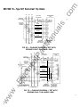
If the a-c control voltage is any voltage other than
tM
FIG. 32C - CLOSED GAP C H ECK
2081240V ac, a control power transformer (also remotely
mounted with respect to the breake" must be used. This
must have a minimum rating of 100 volt-amperes.
When installed, the voltage to be monitored is connected
across terminals No. 1 and No. 2 of the static delay box.
The coil of the tripping unit is connected across terminals
No. 4 and No. 5 of the static box through the secondary
disconnects of the breaker. The secondary disconnects to
be used will be shown on the breaker wiring diagram.
ca
lP
ar
Undervoltage devices trip the breaker when the armature
opens. This causes an extension on the armature to strike
the paddle on the trip shaft. An extension of the other end
of the armature. When the armature is released, this exten
sion stops against a stop which is factory set. To check
positive trip, the armature should be held down, the end of a
1 132-inch diameter wire should be inserted against the stop,
and the armature released. If this trips the breaker, the set
ting is correct. The place to insert the wire is shown in Fig.
320. Note that only the tip of the wire is to be against the
stop.
tri
If the undervoltage device does not have positive tripping
ability, the adjustment screw of the trip paddle assembly on
the trip shaft may be turned in increments of half turns until
the check is successful.
When the undervoltage device is closed and the breaker
mechanism is reset, there must be clearance between the
7.9
lec
trip paddle and the device armature.
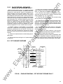
STATIC TIME·DELAY UNDERVOLTAGE
.E
The static time-delay undervoltage system consists of a
time-delay unit which controls an instantaneous under
voltage device. The time-delay unit is separately mounted
in the sw i tchgear and the undervoltage device is mounted
on the breaker. Table S lists the catalog numbers available.
w
CAT. NO.
ww
TAKYUVT- 1
TAKYUVT-2
TAKYUVT-3
G- & '
G- r=;c\
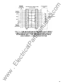
TABLE 5
No more than one undervoltage tripping device should
be used in conjunction with one static time-delay unit.
The static time-delay undervoltage can also be furnished
with a thermotector control unit. Overheating of motor win
dings causes the thermotector, imbedded in the motor win
dings, to open. This de-energizes the undervoltage device
on the breaker and drops the motor load.
7.9.1 ADJUSTMENTS
In the event the system fails, the following checks are
recommended to determine whether the undervoltage
device on the breaker of the static time delay unit is the
faulty component.
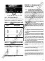
1 . Check input voltages across terminals 1 and 2 on the
static box. See Table 5 for these values.
2. Check output voltages on terminals 4 and 5 with the
undervoltage device connected. See Table 5 for values.
TI M E-DELAY U NITS
APPROXIMATE STEADY STATE
DC OPERATING VOLTAGE
TERMINALS
4 & 5
NOMINAL DC COIL
RESISTANCE
(OHMS)
@ 25°C
50
440
250VDC
100
1600
208/240 VAC
1 10/125
1600
CONTROL
VOLTAGE
TERMINALS
1 & 2
125
voc
25
.c
om
SECTION 7-Breaker Maintenance (Cont.)
3. Check resistance of the disconnected undervoltage
device. See Table 5 for values.
The undervoltage device must be calibrated through the
time-delay unit after the device pick up has been adjusted.
A .008 inch minimum closed gaiJ must exist between the ar
mature and magnet as shown in Fig. 32C. Refer to Section
7.8.3 and Table 24.
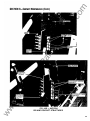
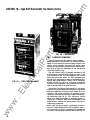
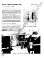
7.1 0 ELECTRIC LOCKOUT DEVICE
FIG. 33 - ELECTRIC LOCKOUT DEVICE
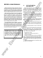
7.1 1
BELL ALARM
an
This device is used to give a remote indication of the
breaker's having tripped open through the action of one of
Its automatic protective devices. It will not be activated by
manual tripping or the action of the shunt trip. A remotely
mounted protective relay energizing the shunt trip will there
fore not result in the remote alarm action.
tM
The electric lockout device utilizes an undervoltage
device to keep the breaker from resetting its mechanism if
the breaker is open and the undervoltage device coil is not
energized. The breaker thus cannot be closed unless
voltage is on the coli. Once the breaker is closed, loss of
voltage will not trip the breaker because, in the closed posi
tion, a mechanical link is used to hold down the armature of
the device. See Fig. 33. This arrangement provides a
means of electrically interlocking two breakers so that they
cannot be closed at the same time. Each undervoltage coil
may be wired in series with a "B" auxiliary switch contact
on the other breaker for cross-interlock purposes.
ua
ls
See instruction Sheet GEH-4545 for more detailed infor
mation, including schematic diagrams and circuit descrip
tion.
ar
On each breaker having an electric lockout, an arrange
ment is made which will allow breaker closing with the coil
de-energized. This is provided to allow "start-up" on "dead"
systems. Figure 34 shows this device. The push slide
shown is located in the opening in the lower part of the
escutcheon. This breaker door must be opened to gain
access to it.
The bell alarm circuit may be turned off by pushing in the
manual trip or by energizing the shunt trip. In the latter case,
a normally open contact of the bell alarm switch must be
wired in parallel with the "A" auxiliary switch contact in the
shunt-trip circuit Closing the breaker will also tum off the
alarm.
lP
' ---2EM£i
:,.�
I ··�·· \,
1 _}.
' ..- I
.
tri
I
.
I
ca
MAIN SHAFT
CLOSED)
l
"""
·
J_ 'l� �··· I·"-�
""' ·. '
.
lec
/TiI
I
I
HOLD- IN
The bell alarm device may be equipped with a lockout
link which will lock the breaker open until the bell alam
device is reset.
�
..
�
The bell alarm is not a standard device and is supplied
only when specified on the breaker order.
7.1 1 .1
OPERATION
Referring to Rg. 35: the bell alarm mechanism Is ac
tivated by a crank which is assembled to the breaker's main
shaft. When the breaker opens, a pin attached to this crank
moves the alarm link against the switch and locklever Of
provided). This activates the switch contacts. It also moves
the locklever adjustment screw against the trip shaft padd le
keeping the breaker trip free.
.
ww
w
.E
\:
FIG. 34 - ELECTRIC LOCKOUT BY-PASS
26
POINT
ENGAGEME
�� · �
,40
�
""' ./
FIG. 35 - BELL ALARM DETAILS
.c
om
'
SECTION 7-Breaker Maintenance (Cont.)
ADJUSTMENTS
The bell alarm Is mounted on the right hand side of the
breaker at the rear of front frame It is located under the
mechanism's main shaft.
.
The bell alarm is removed by passing it through a cutout
in the rear bend of the front frame, slipping it between the
front frame and trip shaft and out through the bottom of the
breaker as follows:
1 . Remove the 4 bell alarm mounting screws from the
bottom of the front frame
2. If the crank which Is part of the main shaft has a bell
alarm activating pin assembled to both sides, remove these
pins.
3. 1nsert the flat of the maintenance handle between the
top of the left hand side buffer block and the end plate
assembly. This should eliminate any Interference from the
main shaft during the bell alarm removal.
4. The trip shaft must be moved to allow the bell alarm to
fit beteen It and the front frame. Remove the retaining ring
holding the right hand trip shaft bearing to the mechanism
frame. Slide the bearing from the frame and along the trip
shaft. There will now be enough trip shaft movement to slip
the bell alarm past.
5. Install the replacement bell alarm in reverse order.
6. Check the adjustments given in Section 7.1 1 2
.
tM
If a breaker is equipped with a bell alarm/lockout device
originally, all the adjustments are made at the time of
assembly. Switch operation is controlled by means of
shims of insulating material placed between the switch
body and the bracket to which it Is fastened. The adjust
ment screw is positioned so that when the locklever is in its
activated position, it holds the breaker mechanism latch in
the tripped position.
REPLACEMENT
ua
ls
7.1 1 .2
7.1 1 .3
an
The mechanism i s reset by disengaging the side latch
link from the upper latch link or by closing the breaker if a
locklever is not provided. The side latch link, is activated
only by pushing the TRIP button or operating the shunt trip.
A slide attachment on the TRIP button shaft moves
against the side latch link when the TRIP button is pushed.
This slide attachment is factory adjusted to activate the
side latch before the breaker is tripped. A second arm on
the shunt trip also activates the side latch link when the
shunt trip is energized.
ar
Check that TRIP button shaft and shunt trip operations,
besides tripping the breaker, displace the side latch and
prevent the bell alarm switch from operating. The other trip
devices and interlocks must activate the bell alarm when
they open the breaker.
.E
lec
X- R E LAY
OR
K - R E LAY
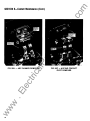
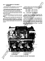
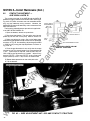
ELECTRICAL CONTROL COMPONENTS
tri
W RELAY
7.12
ca
lP
The bracket assembled to the TRIP button shaft must be
adjusted so that it will displace the side latch when or
before the shaft opens the breaker. Maintain a .030 inch
minimum gap between the bracket and the side latch when
the breaker is closed. A .187 inch depression of the TRIP
button must not trip the breaker, but a .375 inch must trip
the side latch.
the breaker and
A bell alarm with a lockout assembly or a bell alarm in
stalled on a 2000 amp frame (AKRT 50/SOH) breaker may not
work with the above procedure. If this is the case, the
breaker front and back frame will have to be separated.
ww
w
CHARGING
MOTOR
G SWITCH
F SWITCH
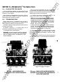
AG. 36A
-
ELECTRICAL CONTROL COMPONENTS
27
COMPONENT REPLACEMENT
1
To gain access to the electrical control components,
the breaker's front escutcheon must be removed. Type B
and D breakers require that both the deep molded escut
cheon and the shallow steel escutcheon be removed.
Before removing the front escutcheon on Type A or B
breakers, a supporting block should be placed under the
front frame to keep if from tlipping forward.
2
Referring to Fig. 36A, the X-relay or K-relay and F and G
switches are mounted on the same bracket. This mounting
bracket is fastened to the right-hand mechanism side frame
by two hex-head 1/4-20 screws. Removing these screws
allows the bracket to be pulled forward from between the
mechanism side plates. The W-relay must also be un
fastened from the left side frame to allow enough freedom
for all the devices and the wiring harness to be taken from
between the side frames. With the bracket removed, in
dividual devices can be replaced easily.
\
4
6
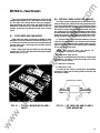
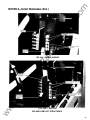
4.
SPRING WASHER
5. WASHER .032•
6. MOTOR DRIVE PIN
an
RETAINER RING
WASHER .010•
3. PAWL ASM
FIG. 36B - DRIVING PAWL ASSEMBLY DETAILS
The holding pawl pivots on a pin which is assembled to
the mechanism frame. Refer to Fig. 36C. To replace the
holding pawl:
1 . Remove the front escutcheon for accessibility.
2. Using the maintenance handle, rotate the ratchet
ar
The charging motor is secured through three spacers to
the mechanism frame. The front mounting bolt is accessi
ble using a socket and universal joint through the opening
in the side of the breaker's frame. The upper rear mounting
bolt is accessible using a socket and universal joint over
the top of the frame. The lower rear mounting bolt is ac
cessible using a socket and universal joint through the
opening in the frame's side by the buffer assembly. Slow
close the breaker to move the flywheel assembly out of the
way.
1.
2.
5
tM
The closing solenoid is mounted by means of mounting
bracket to the bottom of the breaker frame. The most con
venient way to take off the solenoid is to remove the moun
ting bracket and then disconnect the solenoid from the
bracket. The pin connecting the armature to the closing
link must also be removed.
3
ua
ls
7.12.1
.c
om
SECTION 7-Breaker Maintenance (Cont.)
enough to disengage the holding pawl.
3. Remove the retaining ring and washer from the pivot
ca
lP
pin.
The ratchet on the camshaft is removed by driving out
tri
the rol l pin which fastens it to the camshaft. Before this
can be done, the charging motor must be removed and the
closing spring arranged for "slow-dosing" as described
lec
earlier. Tum the camshaft, using the maintenance handle,
until the roll pin is well started, tum the camshaft to gain
enough space for the roll pin to clear the breaker frame.
Before removing the ratchet note the position of the
ratc het s roller or mar1( the ratchet's hub and the camshaft.
'
4. While holding the spring pressure from the holding
pawl, remove the existing pawl and slip on the new pawl.
5. Install the washer and retaining ring.
6. Verify that the holding pawl engages a minimum of 4
ratchet laminations.
7. Verify that the holding pawl pivot pin is perpendicular
to the mechanism frame. The hardware which assembles
the pivot pin to the frame must be torqued to 250 in-lbs
minimum. If this hardware must be retightened, add LOG
TITE 290 to the shaft threads.
8. Install the front escutcheon. Tighten the escutcheon
hardware to 80 ± 10 in-lbs.
3
When replacmg the ratchet, be sure It Is oriented with
respect to the camshaft as it was originally and not di spl ac
ed 180 degrees Align the mark made on the hub with the
4
shaft.
.E
mark on the camshaft or position the roller as It was. If the
ratchet is displaced 1� degrees, the holes in the ratchet's
hub wil l not completely line up with the holes in the cam
w
The driv1ng pawl I S assem bl ed to the charging motor's
drive pin as shown 1n Fig. 36 8 . To replace the driving pawl:
1 . Remove the charging motor.
2. Remove the retaJning ring from the drive pin. Slip off
ww
the components.
3. Wipe off any grease or dirt from the drive pin. DO NOT
LUBRICA TE.
4. Install the
28
components as shown.
6
I
5
1.
MECHANISM FRAME
PIVOT PIN
3. SPRING
4. WASHER .032"
2.
5. PAWL ASM
WASHER .Q10•
7. RETAINING RING
6.
FIG. 36C - HOLDING PAWL ASSEMBLY DETAILS
7
.c
om
7.1 2.2
F AND G SWITCH ADJUSTMENT
For proper electrical operation, the F and G mechani
cally operated switches must operate at the proper point in
the closing cycle. If these switches are to be replaced,
measure the distance between the tip of the switch button
and the bracket on which they are mounted. When the new
switch is mounted, duplicate the measured dimension,
then check for proper operation.
When a normal closing operation occurs, the ratchet
usually comes to a stop with an arbitrarily designated
ratchet tooth No. 1 , Fig. 37, engaged by the holding pawl.
This tooth is the one which is In line with an I maginary
line passing through the centers of the camshaft (2) and
the rivet opposite the roller on the ratchet assem bly. It Is
matter of no concern If the action stops on a different
tooth, but it is i m portant to positively identify tooth No. 1
by the method described.
ua
ls
an
FIG. 37 - LOCATION OF RATCHET TOOTH
N0. 1
tM
To check the switch action, after tooth No. 1 has been
identified, turn the camshaft with the maintenance handle
and count the teeth as they pass the holding pawl. By using
a continuity tester, observe when the switches operate as
the ratchet turns. The normally open F switch on the left will
close, and the G switch will open.
1 TOOTH
Electrical breakers should operate the switches while
moving from tooth No. 1 0 to tooth No. 1 1 .
7.1 3
lP
ar
If this check shows that an adjustment is needed, the
switch to be corrected can be moved closer to or farther
away from the paddle which operates the switches. A very
thin open-end 5/8-inch wrench will be needed to loosen or
tighten the nuts which fasten the switches to the bracket.
DRAWOUT MECHANISM
ca
The drawout mechanism shown in Fig. 38 moves the
breaker through the DISCONNECTED, TEST, and CON
NECTED positions. Fig. 39 shows how the d rawout
mechanism is mounted to the breaker.
lec
tri
As the ra ck i ng handle is turned, the internally threaded
trunn1on moves on the screw threads, rotating the hex
shaft. on the ends of which are fastened the arms which
engage the f 1xed pins in the drawo ut e nclos u re .
.E
The trunn1on travels between the two jamb nuts on the
end of t he screw. and the adjustment sleeve, which stops
the trunn1on movement at the other extreme point of its
travel The trunnion i s against the jamb nuts when the
breaker 1 s fully racked out and against the sleeve when
fu ll y racked m .
The rackmg mechanism i s adjusted at the factory as
sembly operat1on so that the action is stopped in either
d1rect1on at t he prec1sely correct point. The jamb nuts are
set so
that w he n the trunn1on is against them the relation
between the arms and the equipment pins they engage is
ww
w
shown m F1g 38 The length of the sleeve, which is free to
slide on the threaded shaft , IS controlled by the amount of
thread engagement between the sleeve and its collar. This
lengt h 1s a dJ usted to stop the trunn1on when the distance
between the ends of the equipment and breaker studs is
.03 2 " to . 2 1 8 After th1s adJustment is made, the sleeve
and 1ts collar are locked together by the set screw.
.. .
29
.c
om
tM
an
ua
ls
SECTION 7-Breaker Maintenance (Cont.)
ww
w
.E
lec
tri
ca
lP
ar
FIG. 38 - D RAWOUT MECHANISM DETAI LS
30
FIG. 39
-
RACKING MECHANISM INSTAL LED
.c
om
SECTION 7-Breaker Maintenance (Cont.)
B UFFER ASSEMBLY
When the break�r is opened, the end plate assembly is
driven against the opposite end of the buffer assembly.
The buffer is a stop absorbing the opening energy of the
mechanism. See Fig. 41 .
ca
lP
ar
tM
an
When the breaker is closed, the energy in the closing
spring is transferred to the main s haft through the
mechanism. The main shaft then drives the contacts
closed. The end plate assembly on each end of the main
shaft is driven against the buffer assembly shown in Fig.
40. This prevents the mechanism from overdriving the
contacts.
ua
ls
7.1 4
ww
w
.E
lec
tri
FIG. 40 - BUFFER/END PLATE R E LATIONSHIP-BR EAKER CLOSED
FIG. 41 - B U F FE R/END P LATE R ELATIONSHIP-BR EAKER OPEN
31
.c
om
SECTION 7-Breaker Maintenance (Cont.)
7.1 4.1
NEOPRENE WASHERS
BUFFER ADJUSTMENT
ua
ls
Referring to Fig. 40, with the breaker closed and the
mechanism not reset, a .005 " min. clearance must exist
between the end plate assembly and the buffer nut as
shown. Thi s dimension is factory set. It can be reset by
Hold the nut with a
tightening the buffer nut.
screwdriver and tighten using a socket on the bolt head
opposite the nut. When tig htening this assembly don't
over compress the neoprene washers by overtightening
the assembly. These washers absorb the breaker open
i ng shock.
7.1 5
TRIP LATCH ADJUSTMENT
ar
The reset position of the trip latch is set by the adjust·
ment screw shown in Fig. 43. The adjustment is correct if
three and one-half turns of the adjustment screw causes a
closed breaker to trip. If this check is made, the screw must
then be set back, or unscrewed, three and one-half turns.
tM
Fig. 42 shows a buffer assembly prior to being installed
in a breaker. The dimensions given establish the number of
spacers that are used.
an
Referring to Fig. 41 , with the breaker open, a .040"
maximum clearance can exist between either of the end
plate assemblies and the buffer bolt heads as shown. If
a larger clearance exists, close it up by unscrewing the
buffer assembly i nvolved.
-
BUFFER ASSEMBLY
ww
w
.E
lec
tri
ca
lP
FIG. 42
t---- 1 .93 ----
32
FIG. 43
-
TRIP LATCH ADJUSTMENT
8.1
.c
om
SECTION 8-Contact Maintenance
ARC CHUTE REMOVAL
AND INSPECTION
There are two types of arc chute construction used on
the 800 thru 2000 ampere breakers. They are the ceramic
type shown in Fig. 5 and the molded type shown in Fig. 6.
The ceramic type uses a two piece porcelain frame to
enclose its internal parts. The molded type uses a one
piece, glass-filled polyester frame.
When contacts are replaced, they must be adjusted to
ensure that the proper amount of force is developed be
tween the movable and stationary contacts when the
breaker is closed. This is called the "wipe" adjustment.
"Wipe" is the distance through which the stationary con
tacts move when the breaker closes. It is measured bet
ween the point of contact on a stationary contact when the
breaker is open, and the position of the same point when
the breaker is closed. The actual wiping motion is greater
because the contacts over-travel. "Wiping" imparts a slid
ing or "scrubbing" action to the contacts.
The 800 ampere arc chute is different from the 1600 and
ampere arc chute, which are identical. Therefore, the
800 ampere arc chute cannot be interchanged with the
1 60012000 ampere arc chute. Also note that a breaker must
have either all ceramic or all molded type arc chutes install
ed, do not intermix on the same breaker.
an
The arc chutes are held in place by retainers secured by
bolts through the mechanism frame. The ceramic type
uses two retainers and the molded type uses only one. To
remove the arc chutes:
1 . Loosen and back off the retainer bolt locking nut from
the mechanism frame. They do not have to be removed.
tM
The wipe adjustment influences proper arc transfer dur
ing interruption of fault currents. "Transfer" of the arc is its
forced sequential movement from the intermediate con
tacts to the arcing contacts to the arc runner and finally to
the arc quencher where it is dissipated and extinguished. It
is recommended that contact wipe be checked periodically
during normal maintenance inspections.
2000
ua
ls
Breakers subjected to frequent interruption of high cur
rents may eventually require replacement of their contacts.
The general rule for determining need of replacement is
the loss of one-half or more of the mass of the contact tip
material. Roughening or light pitting of the contact surface
does not indicate loss of ability to carry or interrupt current.
2. Loosen the retainer bolts until the retainer(s) can be
removed.
lP
ar
3. With the retainer(s) removed, lift the arc chutes off for
inspection.
tri
To install the arc chutes:
1.
Replace the arc chutes over each pole unil
2. Locate the retainer(s).
3. Tighten the retainer bolts until the arc chutes are
secure. There may be some side to side motion of .the arc
chutes, but there must not be any front to back motion.
Torque the retainer bolts to 30 in-lbs for the molded type arc
chutes and 60 to 1 00 in·lbs for the ceramic type. Do not
over tighten.
4. Tighten the locknuts against the mechanism frame
with 150 to 175 in-lbs torque.
ww
w
.E
lec
7.4
ca
CAUTION : BEFORE DOING ANY OF THE FOL
L O WING CONTA C T A DJUSTMENT AND RE
PLA CEMENT WOR K, MECHANICAL L Y DIS
CONNEC T THE CLOSING SPRING FROM THE
MECHANISM CAM SHAFT AS DESCRIBED UN
DER SLOW CLOSING THE BREAKER, SECTION
Inspect each arc chute for excessive burning and erosion
of the arc plates and arc runner. Also look for fractures,
damage to the liner material used in the molded arc chute
and damage to the insulation material used in both arc
chutes. Check for any missing parts.
33
.c
om
SECTION 8-Contact Maintenance (Cont.)
8.2
CONTACT ADJUSTMENT
AKR 30130H & AKRU 30
The following wipe adjustment procedure is applicable
to all AKR-30 types:
1 . Open the breaker, remove arc quenchers.
an
PIVOT
STUD
FIG. 45
0.250• M EASUREMENT POINT
WIPE ADJUSTMENT 800 AMP
CONTACT STRUCTURE
-
ar
4. Once the gap dimension is set, verify that the torque
required to just tum the adjustment nut is greater than 40
in-lbs. If less torque is required, carefully add LOCTITE 220
to the adjustment nut threads. Wipe off any excess LOC
TITE. Once the LOCTITE is set, recheck the torque valve.
5. Repeat above procedure on the other pole units.
t
tM
2. Slow-close the breaker. The cam roller must be supported by the cam and not the prop. Refer to section 5.3.
3. Select one pole and, using a flat or wire feeler gage,
measure the gap between the top contact and its pivot stud
as shown in Fig. 45. As necessary, adjust the gap to 0.060
± 0.020 inch by turning the wipe adjustment nut shown in
Fig. 46.
ua
ls
The contact structure of the AKR 30 and the AKRU 30
breakers is slightly different from the AKR 30H. Referring to
Fig. 44 A & B, both structures use one moveable contact
arm, and two stationary arcing contacts. However, the
AKRJAKRU 30 uses three stationary main contacts and the
AKR 30H uses four.
ww
w
.E
lec
tri
ca
lP
6. Trip the breaker.
34
FIG. 46 - WIPE ADJUSTMENT N UT-800 AMP CONTACT STR UCTUR E
ww
.c
om
w
.E
lec
tri
ca
lP
ar
tM
an
ua
ls
SECTION 8-Contact Maintenance (Cont.)
FIG . 448
-
A K R 30H
800 AMP CONTACT STR U CT U R ES
35
.c
om
SECTION 8-Contact Maintenance {Cont.)
CONTACT ADJUSTMENT AKR 50150H & AKRU 50
The following procedure Is used to perform the wipe ad
justment.
1 . Open the breaker, remove arc quenchers.
2. Arrange the breaker for slow-closing. The cam roller
must be supported by the cam and not the prop. Refer to
Section 5.3.
3. Select one pole of the breaker and place a thin sheet or
strip of tough insulating material, such as mylar, over the
stationary arcing and intermediate contacts. This strip
should be about two inches wide and must prevent the arc
ing and intermediate contacts from making contact when
the breaker is closed.
6. Facing the breaker, tum the wipe adjustment stud
shown in Fig. 47 clockwise until the checker indicates that
the main contacts are separated.
7. Tum the stud counter-clockwise until the main con
tacts just touch.
a From this point, advance the stud counter-clockwise
270 degrees. This will be 4-1� flats.
9. Once the adjustment is complete, verify that the torque
required to just tum the adjustment nut is greater than 40
in-lbs. If less torque is required, carefully add LOCTITE 220
to the adjustment nut threads. Wipe off any excess LOC
TITE. Once the LOCTITf is set, recheck the torque valve.
10. Trip the brtrclker, remove the insulating strips.
1 1 . Repeat the above procedure on the other two poles.
ww
w
.E
lec
tri
ca
lP
ar
4. Using the ratcheting.maintenance handle, slow-close
the breaker with tl}e insulation held in place. Examine the
insulation to make sure it "over-hangs" below the in
termediate contacts, but not enough to cover the main con
tacts.
5. Attach a continuity checker (bell-set, light, or ohm
meter) between the upper and lower stud. The checker
should indicate continuity exists.
ua
ls
·
an
The contact structure shown in Fig. 47 is used by all
AKR50 breaker types. This structure uses two movable
contact arms. Each arm acts against a stationary arcing, a
stationary intermediate and three stationary mains.
tM
8.3
36
FIG. 47 - 1 600 AMP CONTACT STR UCTURE
1 . Open the breaker.
The contact structure shown in Fig. 48 is used by all
AKRT 50 breaker types. This structure is similar to the AKR
50 structure. There are two movable contact arms, each
acting against single stationary arcing and intermediate
contacts and four (not three) stationary mains.
2.
ua
ls
4. Screw the driving link completely into the insulating
link.
5. Back out the driving link two and one-half turns. Ex
ceed this by whatever amount is necessary to properly
position the link within the movable contact arms.
6. Install the coupling pin and retainer rings.
·
7. Using the maintenance handle, slow-close the
breaker and observe that all eight stationary main contacts
move away from their stops. If this condition is not
achieved, open the breaker, again remove the coupling pin
and back out the driving link an additional half turn.
8. Reassemble, reclose the breaker and recheck wipe.
9. Repeat the above procedure on the other two poles.
tM
On the AKRT-50 the proper amount of contact wipe
exists if, on a closed breaker, all of the stationary main
contacts have moved away from their stops. This condition
can be checked visually by removing the arc quenchers,
closing the breaker and verifying that all eight stationary
main contacts are "lifted off" their stops. Should wipe ad
justment appear necessary, proceed as follows:
Arrange the breaker for slow-closing.
3. Selecting one pole, drift out the coupling pin and
detach the driving link from the movable contact arms.
There are two designs used to connect the movable
contact arms to the insulated link. This results in two con
tact adjustment procedures depending on which design
the breaker has.
In the original design the two movable contact arms are
pin-coupled to a metal driving link whose opposite end is
threaded and screws directly into the insulating link. This
arrangement omits the wrench-operated wipe adjustment
stud provided on the AKR-30 and -50 frames. Instead, wipe
is adjusted by detaching the driving link from the movable
contact arms and then rotating it with respect to the insulat
ing link.
.c
om
CONTACT ADJUSTMENT
AKRT 50/SOH
an
8.4
ww
w
.E
lec
tri
ca
lP
ar
In the existing design, the metal driving link uses the
same adjustment as the AKR 50. To perform the wipe
adjustment on this design follow the procedure for the AKR
50, Section 8.3.
FIG. 48 - 2000 AMP CONTACT STRUCTUR E
37
.c
om
SECTION 8-Contact Maintenance (Cont.)
8.5
STATIONARY CONTACT
IDENTIFICATION
ua
ls
The stationary arcing, intermediate, and main contacts
each have a different function during current conduction
and current interruption. For this reason, these contacts
are made using different material compositions. Also, the
different functions require that the contacts be replaced in
configurations shown in Figs. 44, 47 or 48.
ar
tM
an
Fig. 49 shows the stationary contacts and how they
differ from one another. The 800 amp main and arcing
contacts are rectangular, but the arcing contacts have
two of their corners notched. The 1 600/2000 amp main
and intermediate contacts are rectangular, but the main
contacts have two of their corners notched. The inter
mediate contacts have all four corners notched.
lec
tri
ca
lP
1 600/2000 AMP
MAIN
ww
w
.E
1 600/2000A MP
INTE R M E D IATE
38
FIG. 49 - STATIONARY CONTACT CONFIG URATION
•
·'- . .l
800 AMP MAIN
'� .'
.�
.c
om
8.6
8.7
CONTACT REPLACEMENT
AKR 30/30H & AKRU 30
CONTACT REPLACEMENT AKR 50/50H , AKRU 50 & AKRT 50/50H
Refer to Stationary Contact Identification, Section 8.5
before replacing any stationary contacts.
Refer to Stationary Contact Identification, Section 8.5,
before replacing any stationary contacts.
The stationary contacts are held in place by the contact
springs which pivot the contacts against the contact stop,
refer to Fig. 45. To replace contacts:
The stationary intermediate and main contacts are
replaced just like the stationary contacts on the 800
ampere breakers. Refer to steps 2 & 3 in Section 8.6
2. Release each contact spring by holding the contact,
extending the spring, and removing it from the contact.
The end pieces on each spring have a small hole for inser
ting a spring puller. A suitable puller can be fashioned by
forming a hook on the end of a length of .062 " diameter
steel wire.
Referring to Fig. 50, the stationary arcing contacts are
replaced as follows:
1 . Remove the arc runner and the flat insulation
assembled underneath the arc runner. It is secured with
four screws. When removing the lower screws, use care
not to damage or misplace the insulating washer found
under each of these screws, see Fig. 50A.
2. Remove the arcing contact pivot. Clean off the ex
isting lubrication found on the pivot area Replace with
D50RD38 (MOBIL 28), see Fig. 50B.
ua
ls
1. Remove the arc runner. It is secured by two screws
into the base and one screw into the contact stop.
an
A spring puller is available for this use and may be
ordered under Cat. No. 286A8168G1 .
3. Clean off the existing lubrication o n the stud's pivot
area. Replace with a small amount of D50HD38 (MOBIL
28) before installing new contacts.
4. Torque the upper arc runner mounting screws to 45
± 5 in-lbs. Torque the lower screw to 35-40 in-lbs.
3. Remove the Insulating spacers, contact pin and arcing contacts, see Fig. 50C.
tM
4. Reassemble the reverse of above. Make sure that the
insulating spacers and insulating washers are properly in
stalled. Torque the arc runner hardware to 45 ± 5 in-lbs.
The movable contacts are removed as follows, referring
to Fig. 46.
ar
The movable contacts are removed in a similar manner
as the 800 ampere breaker movable contacts. Refer to
Section 8.6. When removing the pivot pin from a 2000
ampere (AKRT 50/50H) contact assembly, the pivot pin
from the opposite contact assembly must be slightly
removed. This provides enough clearance to completely
remove the pivot pin.
1 . Using a right angle tru-arc pliers, remove the tru-arc
retainer on the coupling pin. Drift out the coupling pin.
3. Slip out the contact arm.
lP
2. Remove the pivot pin hardware and spring from one
side of the pivot pin. Carefully remove the pivot pin.
4. Place a thin film of D50HD38 lubrication on the pivot
�":'""'"":""'����""':'":'7',,....,..,_�� ""�!:""!':
.
• . ·. _
-
·.
.- ·
··
.
. ..
..
·
ww
w
.E
lec
tri
ca
surfaces of the new arm. Clean any existing lubrication �-'�'
from the pivot pin and place a small amount of D50HD38 ;;�::,
on it.
5. Install the new arm, insert the pivot pin, and replace .
the pivot spring �nd hardware. Tighten the pivot pin hard- > ·�
ware to 90 ± 5 1n-lbs.
FIG. 50A - ARC RU N N ER
STATIONARY CONTACT - 1 600/200 AMP
REPLACEM ENT CONTACT STRUCTU RE
39
.c
om
lP
ar
tM
an
ua
ls
SECTION 8-Contact Maintenance (Cont.)
ww
w
.E
lec
tri
ca
FIG. SOB - ARC RU N N ER REMOVED
40
FIG. SOC - ARCING CONTACT
PIVOT REMOVED
.c
om
SECTION 9-Fused Breakers
FUSE SIZES AND MOUNTING
Table 6 lists the range of fuse sizes available for these
breakers. The Class L fuses are mounted as shown in Fig.
51 . Other than the SOOA size, which has a single mounting
hole per tang, each L fuse tang has two holes sized for
one-half inch bolts.
This fuse provides a melting time-current characteristic
that coordinates with 1 600A trip devices. Compared physi
cally with a 2500A NEMA Class L fuse, the special fuse is
more compact (shorter); its tangs are specially configured
and offset to achieve the required pole-to-pole fuse spac
ing ; a special primary disconnect assembly mounts directly
on the outboard tang of the fuse. Considering their unique
mounting provisions, when replacing these fuses the fol
lowing procedure should be adhered to ( Refer to Fig. 53):
a) Remove the primary disconnect assembly from the
fuse tang, accomplished by first loosening the two keys
via their holding screw and pulling them u pward and out.
After the keys are removed, pull the disconnect assembly
off the end of the fuse tang.
N OT E : This removal does not disturb
disconnect's clamping force adjustment.
the
tM
Class J fuses rated 300 thru 600A have one mounting
hole per tang. The 300, 350 and 400A sizes require copper
adapter bars per Fig. 52.
SPECIAL 2500A FUSE FOR AKRU-50
ua
ls
9.1
9.2
an
There are two types of fused breakers; AKRU 30, 800
ampere frame and AKRU 50, 1 600 ampere frame. Except
for the open fuse lockout device and the integrally
mounted fuses on the upper studs, the AKRU-30 and -50
breakers are identical to the unfused AKR-30 and -50
models. Overcurrent trip devices are the same for both
types.
b) Remove the upper barrier.
ar
c) Detach the inboard end of the fuse by removing the
two 1 /2 inch - 1 3 bolts. A ratchet and socket with a short
extension will be requied.
d) Remove the heat sink.
f) Install the new fuse by reversing the disassembly
procedure. Ensure that the mating faces of the fuse and
heat sink are clean.
ca
lP
e) Remove the fuse.
.E
lec
tri
ADAPTER B ARS (COPPER)
-
TY PI CA L MOUNTI NG CLASS L
FUSES
FIG. 52
-
300 THRU 600 AMP CLASS J
FUSE MOUNTING
ww
w
FIG . 51
41
.c
om
SECTION 9-Fused Breakers (Cont.)
ua
ls
CAUTION: WHEN REPLACING THE FUSE IN THE
LEFT POLE (FRONT VIEW) OF THE BREAKER,
NOTE PAR TI C ULARL Y THA T THIS FUSE IS
MOUNTED DIFFERENTLY THAN THE OTHER TWO
FUSES. A S SHOWN IN FIG . 54, FOR THIS PHASE
THE FUSE IS ROTA TED 1 80 DEGREES ABOUT
ITS AXIS S O THA T I TS INBOARD TA N G IS
POSITIONED BENEATH THE BREAKER S TUD.
THIS TANG IS OFFSET WITH RESPECT TO THE
OPPOSITE END SO THA T ROTATING THE FUSE
DOES NOT ALTER THE POSITION OF THE PRI
MARY DISCONNECT.
an
0
FOR THIS POLE ONLY,
FUSE IS ROTATED 1 80
TO POSITION TANG
BENEATH
STUD
FRONT OF BREAKER
4 . Upper Ba r r i e r
5 . Primary Di s c onnect
1 . Spe c ial Z S OOA Fu s e
Z . Di s c onnect Key
0
ca
B reaker
42
L
30
l
I
l
I
50
-
�
AKRU 50-2500A FUSE TANG POSITIONS
-
!
Ampere
Rating
I
Gould Shawmut
Cat. Nos.
Fuse
300
A4J
-
350'
A4J 350
-
400'
A4J 400
I
I
i
l
Mounting adapter requ•red - see F 19 52
0
FIG. 54
300'
l
-
Spec1al
A1lru.
0
0
PRIMARY DISCONNECT ASSEMBLY (SEE FIG. 1 3)
MOUNTS DIRECTLY ON OUTBOARD FUSE TANG
tri
.E
ww
w
J
0
0
TABLE 6
FUSES FOR AKRU BREAKERS
lec
NEMA
Fuse
Clan
600V
60 Hz
•
2500A. FUSE
CAT. NO.
GF9F2500 AK
AK RU 50 WITH SPECIAL
2500 AMP FUSE
lP
FIG. 53
1 TANG BOLT•
HOLES
IN USE
� l •� -�-�
ar
3 . Heat Sink
tM
BREAKER
STUD
FUSE TANGS
POSITIONED ON TOP
OF BREAKER STUD
450
500
600
A4J 450
A4J 500
A4J 600
800
1 000
1 200
A48Y 800
A4BY 1 000 B G
1 600
2000
2500
A4BY 1 200BG
A48Y 1 600BG
A48Y 2000B G
-
Limiter
-
-
-
-
A4BX 800
A4BX 1 000BG
A4BX 1 200BG
A4BX 1 600BG
A4BX 2000BG
A4BX 2500GE
.c
om
SECTION 9-Fused Breakers (Cont. )
9.3
OPEN FUSE LOCKOUT DEVICE
9.3.1
TYPE A AN D B BREAKER OFLO
ADJUSTMENT
an
tM
Type D breakers use the Open Fuse Lockout (OFLO)
shown in Fig. 55. Type A and B breakers use the OFLO
shown in Fig. 56. Both OFLO's work on the same design.
When the fuse opens, the resulting open circuit voltage
activates the OFLO's phase solenoid when the voltage
level reaches approximately 90 VAC. The solenoid's arma
ture then drives a tripping rod against a trip paddle which is
attached to the trip shaft. This causes the breaker to open.
The armature also drives the reset button forward indicat
ing what phase is involved. The reset button linkage also
holds the tripping rod against the trip paddle. The button
must be pushed in to release the tripping rod.
ua
ls
This device automatically trips the fuse breaker if one of
the fuses opens. When this happens, the breaker is locked
open until the reset button of the phase involved is pushed.
The breaker should not be reclosed, of course, until the
opened fuse is replaced.
FIG. 55- TYPE D B R EAKER OFLO DEVICE
ar
To adjust the Type A and B breaker OFLO (Refer to Fig
56) :
a ) Back off tripping rod s o that it will not hit the trip
paddle when a solenoid is activated.
lP
b) Using the maintenance handle, close the breaker.
d) Close the breaker.
ca
c) Manually close the Left pole armature. Screw tripping
rod forward until it moves the trip paddle enough to open
the breaker. Add two full turns.
tri
e) Manually close the Left pole armature again. The
breaker must open and the reset button pop out. In this
condition close the breaker, it should trip-free.
TYPE D B R EAKER OFLO
ADJUSTMENT
To adjust the Type D breaker OFLO:
a) With the breaker in the CHARGED position and the
OFLO reset, adjust the dimension between the end of the
tripping rod and the trip paddle to .062" .093".
•
b) With the OFLO energized, the breaker must TRIP
and the R ESET button must move forward to the front
plate. In this condition, the breaker must be held trip-free.
lec
f) Reset the OFLO, the breaker must now be able to
close.
9.3.2
g) Repeat for Center and Left poles.
h) Check for a . 1 25" minimum clearance between trip
ping rod and trip paddle with the OFLO reset. Check for
.032" m m t m u m overtravel after tripping rod trips breaker.
ww
w
.E
i) Hold tripping rod in position and ttghten its locknut.
43
�
--I/
..
=I
-·-==r
__
--
--
___)_.
ua
ls
1
tM
an
TRIP
PADDLE
ll
I=
.c
om
SECTION 9-Fused Breakers (Cont.)
ar
ARMATURE
RESET
BUTION
ww
w
.E
lec
tri
ca
lP
FIG. 56A-DETAILS
44
FIG. 568-INSTALLED TYP E A OR 8
B R EAKER O FLO DEVICE
.c
om
SECTION 10-Type SST Overcurrent Trip Device
•
1 0.1
OVOI.CWI
I TAIIGET
I
I
ua
ls
The SST is a solid-state, direct-acting, self-powered trip
device system. The SST system consists of the SST pro
grammer unit, current sensors, and a flux shifter trip de
vice. Fig. 57 shows a block diagram of the system.
PROGRAMMER UNIT
I
I
I
1-
CIM:IIIT
I TMW
I
tM
an
Fig. 58 shows a typical SST programmer unit. The pro
grammer unit provides the comparison basis for overcur
rent detection and delivers the energy necessary to trip the
breaker. It contains the electronic circuitry for the various
trip elements. Their associated pickup and time delay ad
justments (set-points) are located on the face plate. De
pending on the application, programmer units may be
equipped with various combinations of Long Time, Short
Time, Instantaneous and Ground Fault trip elements. See
Table 7 for available ratings, settings and trip characteris
tics. Adjustments are made by removing the clear cover
over the face plate, unscrewing (counter-clockwise) the
set-point knob, moving the set-point along the slot to the
new setting, and screwing the set-point knob in. Once all
adjustments are made, install the clear cover to the face
plate.
ar
FIG. 57 - SST BLOCK DIAGRAM
Each target pops out when its associated trip element
operates to trip the breaker. After a trip, the popped target
must be reset by hand. However, neglecting to reset does
not affect normal operation of any trip element or prevent
the breaker from being reclosed.
ca
lP
The SST programmer units can be optionally equipped
with trip indicators (targets). These are pop-out, me
chanically-resettable plungers located across the top of
the programmer's front. Units with a ground fault element
employ three targets: from left to right, the first is for over
load, the second for short circuit (actuated by the short time
and instantaneous elements) and the third for ground fault.
The latter is omitted on units without ground fault.
The programmer unit is mounted to the lower right of the
breaker as shown in Fig. 59. The bracket attached to the
top of the programmer, see Fig. 58, engages with a bracket
mounted to the underside of the breaker's front frame.
TABLE 7 SST TRIP CHARACTERISTICS
SST PROGRAMMER ADJUSTMENT RANGE ( Set Pointa)
SIZe
Frame
in Ampere.
• Sen.or Tap
-
- -- - - - - - --
(
.E
lec
Bnaker
tri
X • Trip Ratinr
Type
(Amperes)
Sen.or
Am.,.re
Tapt
)
(
Pic:k
Lonr Time
<D
)
(•L)
Mult1p ..
or X
@
Time
Delay
Band
(Sec:onds)
- or -
100. 1 50. 225. 300
AKR-30
800
GROUND FAULT
Short Time
(
®
Pic:kup
Multip..
or L
)
Multiple
or L
Multiple
or X
) (
300 . 400. 600, 800
ww
w
AKR-50
AKRT-50
CD
@
300. 400. 600. 800
- or 600. 800 . 1 200 . 1 600
1 600
2000
Pitkup toler ante
1
Pic:kup toltnnte is
11
800 , 1 200 .
1 600 , 2000
��
�
1 0'\
Maximum
22
lntermed.
10
MUiimum
4
®
@
-or -
1 .7&, 2 ,
2.2&, 2.!i,
3, 4 ( Ll
)
@
Time
Delay
Band
(Sec:onda)
.4, .5, .6,
. 8 . 1 .0 .
1 .2 ( X )
3, 4, 5.
6, 8, 1 0 I L )
.6 . . 7 . 8.
.9, 1 .0.
1.1 (X)
®
Pickup
@ (
Time
Delay
Band
(Sec:onds)
®
Instantaneous
Pickup
Maximum
0.35
lntcrmed.
0.21
4, &, 6,
8, 10, 12 (L)
Minimum
0.09&
Maximum
0.30
.25, .3, .4,
.&, .6,
.7 (X)
lntermed .
0.1 6&
Minimum
0.065
.2, .25, .3,
.4, .&,
.6 ( X )
Tame delay shown at 60()'\ or lonl time pickup s.ettinl (6L), It lower limit of band.
Time delay shown at lower limit of band.
45
ar
.c
om
tM
an
ua
ls
SECTION 10-Type SST Overcurrent Trip Device (Cont.)
tri
ca
lP
1 0.2
ww
w
.E
lec
FIG . 58 - SST PROG R A M M ER
46
FIG. 59 - AKR-58-30
C U R RENT SENSORS
The SST system uses two types of current sensors,
phase sensor and a neutral sensor. Fig. 60 shows a phast.
sensor. Fig. 61 shows the neutral sensors available. The
current sensor supplies the power and sig nal inputs
necessary to operate the trip system . Each sensor has four
taps which provide field adjustment of the trip device's
continuous ampere rating.
·
The SST Ground Fau!t trip element operates on the
principle that the instantaneous values of current in the
three conductors (four on 4-wire systems) add to zero
unless ground current exists. On SST's equipped with
Ground Fault, the ground trip signal is developed by con
nectmg each phase sensor in series with a companion
pnmary winding on a ground differential transformer
mounted in the programmer unit. Its secondary output is
zero so long as there is not ground current.
Application of the Ground Fault element on 4-wire sys·
tems w1th neutral grounded at the transformer requires the
add1hona1. separately mounted neutral sensor (Fig. 61 )
mserted 1n the neutral conductor: its secondary is con
nected to a fourth primary windmg on the ground differen
tial transformer. See Fig . 70 . This "fourth-wire" neutral
sensor 1s an electncal duplicate of the phase sensor, in
cludmg taps . Therefore, when taps are changed on the
phase sensors. those on the neutral sensor must be cor
respondingly posit1oned.
When used. the neutral sensor is separately mounted ir
the bus or cable compartment of the switchgear. In draw
out construction. its output is automatically connected to
the breaker v1a secondary disconnect blocks. See Fig. 62.
.c
om
ua
ls
an
MOUNTED
BREAKER
ca
lP
ar
FIG. 60 - SST PHASE SENSOR
WITH TAP BOARD
tM
REAR VIEW
AKR - 50
\
lec
tri
600 - 1600 A
EQUIPMENT ·
MOUNTED
•
800 A
ww
w
.E
300
100 · 3 00 A
FIG. 61 - SST NEUTRAL S ENSORS
FIG. 62 - N EUTRAL SENSOR
S ECONDARY DISCONNECT
BLOCKS
47
.c
om
REPLACEM ENT O F CU R RENT
SENSORS
a) Disconnect the breaker harness from the tap ter
minal board, removing cable ties as necessary. U n·
fasten the term i nal board from the breaker base.
b) At the rear of the breaker, remove the two Allen
head screws to separate the stud connector from the
contact pivot block.
c) Loosen the clamping bolt and remove the stud
connector. Li ft out the sensor and It� tap term i nal
board.
AKA 30/30H - 1 20 ± 10 i n· l bs
AKA 50/50H - 470 ± 1 0 i n· l bs
AKRT 50/50H - 470 ± 1 0 i n· l bs
1 0.3
FLUX S H I FT TRIP DEVICE
T h e F l u x Shift Trip device i s a low-energy, elec·
tromagnetic device which, u pon receipt of a trip
s i gnal from the programmer u n it, tri ps the breaker by
actuating the trip shaft.
The mounting arrangement of this component is I I·
l ustrated in Figs. 64 and 65. An electromagnetic ac·
tuator located on the u nderside of the front frame i s
coupled t o the breaker's trip shaft via a trip rod driven
by the actuator arm. The actuator i s a solenoid whose
armature i s spring-loaded and held in its normal
(Reset) position by a permanent magnet. In this state
the spring is compressed.
ww
w
.E
lec
tri
ca
lP
ar
tM
The sensor may be prevented from s l i pping off the
sensor stud by adjacent accessories. If t h i s exists,
the sensor stud m ust be removed from the breaker
base. The stud assembly is secured to the base with
four bolts which are accessible from the rear of the
breaker.
d) When rep laci n g the stud connector, tighten the
Allen head screws to 250 ± 10 i n·l bs. Tighten th6
c lamping bolt as fol l ows:
ua
ls
Referri ng t o F i g . 63, replacement o f i nd ividual SST
current sensors is accomp l ished as follows:
an
1 0.2.1
48
1.
2.
3.
4.
Flux shift Trip Device
A llen-head Screws
Stud Connector
FIG. 63
Current Sensor
-
5. Tap Terminal B>ard
6. Progr ammer Unit
7 . Clamp Bolt
8. Sensor Stud
AKR-SA-30 B R EAKER WITH SST TRIP DEVICE
.c
om
5. Verify all sockets are inserted to the same depth.
CAUTION : IN THE EVENT THAT THE SST TRIP DE
VICE MUST BE RENDERED INOPERA TIVE TO
ALLOW THE BREAKER TO CARR Y CURRENT
WITHOUT BENEFIT OF OVERCURRENT PROTEC
TION, THE RECOMMENDED METHOD IS TO
SHORTEN THE TRIP ROD BY TURNING ITS AD
JUSTER END FULL Y CLOCKWISE. THIS PRE
VENTS ACTUATION OF THE TRIP SHAFT PADDLE.
tM
The trip device requi res o n ly one adj ustment - the
trip rod length. As shown fn Fig. 66, the clearance
between the trip rod and the trip shaft paddle is gaged
by a 0. 1 25 inch diameter rod. Adj ust gap to 0.1 25 inch
± 0.01 5 inch. To adjust, open the breaker and restore
the breaker mechanism to its Reset position. Loosen
the jamb nut, rotate the adj uster end until the proper
gap is attai ned, then reti ghten the jamb nut to 35 ± 5
i n-lbs.
3. Insert the extractor tool over the female pin.
When the extractor tool bottoms out, depress the
plunger and force the wire/socket assembly out of the
connector.
4. No tool is req uired to i nsert the wire/socket
assembly i nto the connector. Insert the assembly u n
t i l It snaps i nto place.
ua
ls
As the breaker opens, the actuator arm-is returned
to its normal (Reset) position via l i n kage d riven by a
crank on the breaker's main shaft. The permanent
m ag net again holds the armature captive in readiness
for the next trip signal.
1 . Remove the flux shifter leads from the harness.
2. Referri ng to the cabl ing d iag rams in Section 1 0.5,
the flux shifter leads are RED ifl point B and B LACK i n
point E.
an
So long as the actuator remains i n the Reset posi
tion ' the breaker can be closed and opened normally
.
at will. H owever, when a closed breaker rece1ves a
tri p signal from the programmer unit, the actuator i s
energized and its solenoid f l u x opposes t h e mag n �t,
allowing the spring to release the armature; th1s
d rives the trip rod agai nst the trip shaft padd le, tripp
ing the breaker.
ar
The actuator is a sealed, factory-set device and re
q u i res no mai ntenance or field adj ustment. I n case of
malfunction, the complete actuator unit should be
replaced. When making the electrical connector to
the replacement unit, it i s recom mended that the brea
ker harness be cut at some convenient point and the
new actuator leads solder-sp liced thereto.
tri
C RANK
BREAKER
)
CLOSED POS I T I ON
.E
lec
(
ca
lP
The preferred method is to remove the flux shifter
leads from the A M P connector using the A M P extrac
tion tool, Cat. N o. 3051 83 as follows:
(
RESET
L I NKAGE
I{! H ::lla
I
(
w
J
�
'"{=! bi �
TRIP
P A D DLE
ww
\
f
L
SIDE
VIEW
FRONT
-
VIEW
0
....
I
�
,.
0
FIG. 64 - FLUX SHIFT TRIP DEVICE AND OP ERATING LINKAG ES
49
4
lP
3
.c
om
ar
tM
an
ua
ls
SECTION 10-Type SST Overcurrent Trip Device (Cont.)
ca
Bottom view
1 . Actuator
Trip rod adjuster end
Trip paddle
tri
2.
3.
-
ww
w
.E
TRIP PADDLE I N
"
" w ( CHANISW R E S E T
POS I T IO N
FIG . 66
50
-
Top view
4.
Trip shaft
5 . Actuator ar m
6. Reset l inkage
FLUX SHIFT TRIP DEVICE COMPONENTS
lec
FIG. 65
5
TRIP ROD ADJ USTMENT
.c
om
TROU BLESHOOTING
a) Breaker tripping in proper response to overcurrents
or incipient ground faults.
b) Breaker remaining in a trip-free state due to
mechanical interference along its trip shaft.
c) Inadvertent shunt trip activations.
WARNING: DO NOT CHANGE TAPS ON THE
CURRENT SENSORS OR A DJUST THE PRO
GRA MMER UNIT SET KNOBS WHILE THE
BREA KER IS CARRYING CURRENT.
Once it has been established that the circuit breaker
can be operated and closed normally from the test posi
tion, attention can be directed to the trip device proper.
Testing is performed by either of two methods.
1 . Conduct high-current, single-phase tests on the
breaker using a high current-low voltage test set.
2. Test the components to the SST system using por
table Test Set Type TAK-TS1 (Fig. 67) or TAK-TS2.
The applicable test procedures are detailed i n i n
struction Book GEK-64454 and are summarized in Sec
tion 1 0.4.1 .
The TAK-TS1 and TAK-TS2 Test Sets are portable in
struments designed for field checking the time-current
characteristics and pickup cal ibration of the SST's
various trip elements. It can verify the ability of the
Flux-Shift Trip Device to trip the breaker and, in addi
tion, includes means for. continuity checking the phase
sensors. A TAK-TS1 Test Set Is shown in Fig. 67.
The time-current characteristics for the SST Trip
Device are given in curves G ES-6033, G ES-6034 and
GES-6035.
ar
tM
N OTE: For these single-phase tests, special con
nections must be employed for SST breakers
equipped with Ground Fault. Any single-phase in
put to the ground differential transformer will
generate an unwanted "ground fault" output
signal which will trip the breaker. This can be
nullified either by
b) using the Ground Fault Defeat Cable as shown
in Fig. 71. This special test cable energizes a ll the
primary windings of the differential transformer in
a self-cancelling, series-parallel connection so
tha t its secondary output is always zero.
ua
ls
When malfunctioning is suspected the first step in
troubleshooting is to exami ne the circuit breaker and its
power system for abnormal conditions such as:
an
1 0.4
ww
w
.E
lec
tri
ca
lP
a) testing two poles of the breaker in series, or
FIG. 67 - SST/ECS TEST SET, CAT. NO. TAK-TS1
51
SST TEST SET
The TAK-TS1 and TAK-TS2 Test Sets are portable in
struments designed for field-checking the time-current
characteristics and pickup calibration of the SST's
various trip elements. It can verify the ability of the
Flux-Shift Trip, Device to trip the breaker and, in addi
tion, includes means for continuity checking the phase
sensors. A TAK-TS1 Test Set is shown in Fig. 67. The
TAK-TS2 functions identically to and supersedes the
TAK-TS1 device. The TAK-TS2 can also test the Ver
saTrip Mod 2 trip device.
1 0.4.2
RESISTANCE VALUES
For use in troubleshooting, the Common to Tap resist
ance for SST current sensors is given in Table 8 . These
values apply to both phase and neutral sensors.
TABLE 8 - SENSOR RESISTANCE VALUES
Ampere
TAP
1 00
1 50
225
300
WARNING: BEFORE CONNECTING THE TEST SET
an
TO THE BREAKER TRIP DEVICE S YS TEM, EN
SURE THA T THE CIRCUIT BREAKER IS COM·
PLETEL Y DISCONNECTED FROM ITS PO WER
SOURCE. ON DRAWOUT EQUIPMENT, RACK THE
BREA KER TO ITS DISCONNECTED POSITION.
VERIFY THAT THE BREAKER IS TRIPPED.
ua
ls
1 0.4.1
300
400
600
800
tM
Either of two test modes may be employed:
.c
om
SECTION 10-Type SST Overcurrent Trip Device (Cont.)
Resistance In Ohms
between COMMON
and TAP Terminals
2.2 3.3 5.1 6.8 -
2.6
3.9
5.8
7.8
5.3 7.2 1 0.8 1 4.6 -
6.1
8.2
1 2.4
1 6.9
600
800
1 200
1 600
6.4 - 7.6
8.8 - 1 0.4
1 3.5 - 1 5.8
1 9 .4 - 22.8
CAUTION: NEVER DISENGAGE THE HARNESS
CONNEC TOR FROM THE PROGRAMMER UNIT
ON A BREAKER THA T IS ENERGIZED AND CARRY
ING LOAD CURRENT. THIS WILL OPEN-CIRCUIT
THE CURRENT SENSORS, ALLOWING DANGER
OUS AND DAMAGING VOL TAGES TO DEVELOP.
800
1 200
1 600
2000
1 0.2 - 1 2.4
1 5.8 - 1 9.2
22.0 - 26.7
28.5 - 34.7
ca
lP
ar
"A" - Programmer Unit Only. These tests are con
ducted with the programmer unit disconnected from the
breaker. During test, the unit can remain attached to the
breaker or may be completely removed from it.
Test scope:
1 . Verify the time-current characteristics and pickup
calibration of the various trip elements.
tri
2 . Verify operation of the SST target indicators on pro
grammer units so equipped.
Test scope •
lec
" 8 " - Complete Trio Device Svstem. For these tests,
the programmer un1t must be mounted on the breaker and
connected to 1ts wiring harness.
.E
1 . All "A" tests prev1ously described, plus provision for
optionally swrtchrng the programmer's output to activate
the Flux· Shlft Tnp Device and verify its operation by physi
cally tnppmg the breaker.
2. Check phase sensor continuity.
ww
w
In the event that any component of the SST system does
not perform wrthrn the limits prescnbed m test instructions
GEK-64454 . 1t should be replaced .
52
I
The coil resistance of the SST/ ECS Flux shifter device is
approximately 1 6 ohms.
.c
om
d) On G round Fault breakers serving 4-wire loads,
check that the neutral sensor is properly connected (see
cabling diagram Fig. 70). In particular,
( 1 ) Verify that the neutral sensor has the same rating
and tap setting as the phase sensors.
(2) Check continuity between the neutral sensor and its
equipment-mounted secondary disconnect block. Also
check for continuity from the breaker-mounted neutr;il
secondary disconnect block through to the female harness
connector (terminals L and N).
(3) If the breaker's lower studs connect to the supply
source, then the neutral sensor must have its LOAD end
connected to the source.
(4) Ensure that the neutral conductor is carrying only
that neutral current associated with the breaker's load cur
rent (neutral not shared with other loads).
tM
If nuisance tripping is encountered on any breaker
whose SST components have previously demonstrated
satisfactory performance via the TAK-TS1 Test Set, the
sen sors and their connections should be closely
scrutinized. After disconnecting the breaker from all power
sources,
c) Verify that the harness connections to the sensors
meet the polarity constraints indicated by the cabling dia
gram, i.e., white wire to COMMON, black wire to TAP.
ua
ls
When nuisance tripping occurs on breakers equipped
with the Ground Fault trip element, a probable cause is the
existence of a false "ground" signal. As indicated by the
cabling diagram of Fig. 69, each phase sensor is con
nected in a series with a primary winding on the Ground
Fault differential transformer. Under no-fault conditions on
3-wire load circuits, the currents in these three windings
add to zero and no ground signal is developed. This current
sum will be zero only if all three sensors have the same
electrical characteristics. If one sensor differs from the
others (i.e., different rating or wrong tap setting), the dif
ferential transformer can produce output sufficient to trip
the breaker. Similarly, discontinuity between any sensor
and the programmer unit can cause a false trip signal.
an
FALSE TRIPPING-BREAKERS
EQUIPPED WITH GROUND FAULT
1 0.4.3
a) Check that all phase sensors are the same type (am
pere range).
SST CABLING DIAGRAMS
FLUX SHIFT
TRIP DEVICE
PROGRAMMER
UNIT
�-- - -- -
P�+o-K�H<l+- (48V.
del
���� ��� �0 �
ANOOE)
ww
w
.E
lec
tri
ca
lP
1 0.5
ar
b) Ensure that the tap settings on all 3-phase sensors
are identical.
e) lf the preceding steps fail to identify the problem, then
the sensor resistances should be measured. Since the
phase and neutral sensors are electrically identical, their
tap-to-tap resistance should closely agree. See Table 8.
HARNESS
CONNECTOR
LOAD
(AMP 201298·1 )
PROGRAMMER
CONNECTOR
(AMP 201297· 1 )
FIG. 68 - CAB LING DIAG RAM - SST WITHOUT G ROUND FAULT
53
PROGRAMMER
FLUX SHIFT
TRIP DEVICE
,-- UNIT
- -- -
.c
om
SECTION 1 0-Type SST Overcurrent Trip Device
ua
ls
WHITE
BLACK
WHITE
BLACK
tM
LOAD
an
WHITE
CONNECTOR
PROGRAMMER
(AMP 201217·1)
lec
tri
ca
lP
ar
FIG. 69 - CABLING DIAGRAM - SST WITH
GROUND FAULT ON 3-WIRE LOAD
r -UNIT
- -- -
��+o-+-<�H<� (48V. de)
J2!::�'-l-ok •f:..k*- (TO SCR
ANODE)
BLACK
WHITE
BLACK
WHITE
BLACK
WHITE
.E
w
ww
54
PROGRAMMER
FLUX SHIFT
TRIP DEVICE
BLACK
HARNESS
CONNECT OR
4 -WIRE LOAD
CAMP 20 1 298 • 1 1
PROGRAMMER
CONNECTOR
CAMP
201217- 1 )
FIG. 7 0 - CAB LING DIAG RAM - SST WITH
GROUND FAULT ON 4-WI RE LOAD
I
"'
o-t-< '"'
"'
��
�
�
"'
•c�
+A
y
·B
� '"'"'
'"'
NEUTRAL I o-t-< '
y
�
I o4-<
I
Ij
A
c�
B
E
A
II
I I
\\
L_
N
1t
u
K -
M
p
u
I
\
II
I
L ...._
i '""'
L ._
r
I
D
FH -n
I
I I
"'c
"D
F
H
K
r ......,L
N
I
""'M
p
r - - - -,
I
r-,
'"'"'
:l
'"'"' H-0-t'"' �
"'
3
'..
3
'.
'"'"'
�
�:
�
: ! �: · f
ti�t· �
�
+-r-o
� f-H) II
� H-a l
R
"
� R
o-+-< .,
�
L_J
&.-- ----- �oo-..J
FEMALE
MALE
END
END
tM
SENSOR
DISCONNECT
. r--A
.c
om
�
r\. -,
B
I cH--( � E
RAMMER
U NI T
:
""'
ANY SST
PROGRAMMER
UN IT WITH
GROUND FAULT
ELEMENT
ua
ls
CURRENT
SENSORS
PROG
GROUND FAULT DEFEAT CABLE
CAT. NO. TGFD
an
BREAKER
HARNESS
CONNECTOR
L_J
L
_
_
_j
ww
w
.E
lec
tri
ca
lP
ar
FIG. 71 - CABLING DIAGRAM WITH G ROUND FAU LT DEFEAT
CABLE INSERTED BETWEEN BREAKER HARNESS AND SST
PROGRAMMER UNIT - FOR USE DURING SINGLE-PHASE,
HIGH CURRENT - LOW VOLTAGE TESTING
55
.c
om
SECTION 1 1 -Type ECS Overcurrent Trip Device
The ECS is a solid-state, direct-acting, self-powered
trip device system. The ECS system consists of the
ECS programmer unit shown in Fig. 72, current sensors,
and a fl ux shifter trip device. Fig. 73 shows a block
diagram of the system.
ua
ls
The ECS trip system essentially duplicates the SST
trip system described i n Section 1 0 except for the
following:
2. Phase sensors are not tapped. As l i sted in Table 9,
each sensor has only a single ampere rating. A different
sensor is available for each of the tabulated ampere
ratings, which span the same range as SST, see Fig. 74.
3. Neutral sensors are not required because there is
no G round Fault function.
lP
ar
tM
In all other respects the ECS Trip device system
operates and can be treated identically to SST. This in
cludes circuitry, size, construction, component loca
tion, programmer unit set points, performance
characteristics, operating range, q uality, rel iability and
the flux shift trip device: Use the same troubleshooting
and test procedures for single-phase, high current-low
voltage tests or those employing the TAK-TS1 or TAK
TS2 Test Sets. The Ground Fault test procedures, of
course, do not apply. ECS pha&e sensor resistance
values are given in Table 1 0.
an
1 . Programmer units are ltn1ited to combinations of
Long Time, Short Ti me and instantaneous tri p elements
only. The Ground Fault element is not available.
FIG. 72
-
ECS PROGRAMMER UNIT
ca
The ti me·current characteristics for the ECS trip
device are given in curve GE5.6032.
___
w
.E
lec
!,_
tri
•
ww
FIG . 73 - ECS BLOCK DIAGRAM
56
FIG 74
-
ECS CURRENT SENSOR
ECS PROGRAMMER ADJUSTMENT RANGE (Set Points)
X • Trip Rating
1600
2000
AKRT-50
(!)
®
)
Pick
�
(•L)
{ ! }
Mu iple
of X
.6, .7, .8,
.9, 1.0,
1.1 (X)
@
Pickup tolerance is ±. 9%
@
Pickup tolerance is ±. 10%
(Seconds)
Maximum
22
300, 400, 600,
800, 1200, 1600
800, 1200,
1600, 2000
Band ®
Time
Delay
(
®
Pickup
Multiple
of L
)
Time
Delay
Band @
(Seconds)
Instantaneous
Pickup
(
®
Multiple
of L
)
3, 4, 5,
6, 8, 10 (L)
100, 150, 225,
300, 400,
600, 800
800
AKR-50
Sensor
Ampere
Rating
ua
ls
AKR-30
(
Short Time
Long Time
Intermed.
10
Minimum
4
-or-
1.75, 2,
2.25, 2.5,
3, 4 (L)
Maximum
0.35
Intermed.
0.21
Minimum
0.095
4, 5, 6,
8, 10, 12 (L)
an
Type
Frame
Size
(Amperes)
Time delay shown at 600% of long time pickup setting (6L), at
lower limit of band.
Time delay shown at lower limit of band.
tM
Breaker
in Amperes
• SeDSOr Rating
-- - -- --
.c
om
TABLE 9
ECS TRIP CHARACTERISTICS
TABLE 1 0 - SENSOR R ESISTANCE VALUES
Ampere
Rating
ar
Resistance In Ohms
between Terminals
tri
ca
lP
1 00
1 50
225
300
400
600
800
1 200
1 600
2000
3.0 - 3.4
4.4 - 5.0
4.8 - 5.6
6.4 - 7.2
6.7 - 7.8
6.4 - 7.6
8.8 - 1 0.4
1 3.5 - 1 5.8
1 9.4 - 22.8
29.5 - 34.5
1 1 .1 ECS CABLING DIAGRAM
ww
w
.E
lec
�
A A
4
... •• •c
rf>--1-�
- + -+
�
I
I
I'
••
I A
I
I
I
I
I
I
L
I
I
H
'a
H
I
I
f- .J
... - , v- � v
'c
rr r
liED -
I��LAC�<
M«TE
'8
E
(..V dcl
(TO SCR
ANODE I
..
c
IILACI<
M«TE
D
:+-��
IILACI<
M«TE
IILACI<
r -UNT
---�
FlUX SHIFT
,._ DEVICE
H
K
r
L
..-s5
PRODIIAMR
ME
COHHE
CTOR
� 201-"11 COHIECTOR
� 201217 · 1 1
- - --�
FIG. 75. CABLING DIAGRAM FOR ECS TRIP
D EVICE
57
.c
om
SECTION 1 2-MicroVersaTrip™ Trip Device
FAULT TRIP INDICATORS
ua
ls
The optional fault trip indicators are similar to the SST
indicators. They are mechanical pop-out type for identify
ing overload or short circuit over-currents faults when
breakers are ordered without integral ground fault protec
tion. They are also available to identify overload, short
circuit and ground fault trips for breakers supplied with
integral ground fault protection.
Each target pops out when its associated trip element
operates to trip the breaker. After a trip, the popped target
must be reset by hand. However, neglecting to reset does
not affect normal operation of any trip element or prevent
the breaker from being -closed.
1 2.1 .2
REMOTE FAULT INDICATION
Remote fault indication is available in the form of a
mechanical contact which may be incorporated directly
into the customer's control circuitry. This is a Normally
open contact which is activated when its associated target
pops out. When the target is reset, the contact is returned
to its open position. Each contact is rated 0.25 amp at 1 25
VDC and 1 .0 amp ( 1 0 amp in rush) at 1 20 VAC.
,
I
- _j
I
I
NEUTRAL
I
�
� CIRC
R 1--
SUUUING
UI T 'V
.E
�
I
I
L
.'
•2
•3
_
_
_
_
I
SHORT TIU(
PICKuP &
DE LA Y
I
t
SHOR T
oRCUIT
T ARGE T
�
..ST ..... T AHE OVS
PICKuP
I
1
I
GAQvO.IO ' Ac.\ T
POC.. uP &
I
0£ L A •
f
I
I
R E Gc.\ A i f O
'�
lltlC
� A SuPI"l •
_
_
_
I
_
_
__.
ww
.
..
�-- ..� �--.
- -
..
-
..
•
"
..
I<
o<
'"
..
-
.._
..,_
"
-
..
......_ ....,
...
..
.. _.< -- •
..
....... ....
I
-
FIG. 76
MICROVERSATRIP BLOCK DIAG RAM
58
0VERLOAO
T ARGET
I
f
w
E-�.9
I
I
PICKuP &
OELAV
-�
.....
I
I
LOGIC
OA
I
""'
lec
I
f-'-----
LONG TIUE
,_
I
I
J
SWITCH
lP
TAP IIOARD.I I
I a'�
L -----�
-�=-..Jr
cuR'RE'Nisffis15RI
I
501.10
STATE
ca
c
_ __.
I
I
FLUX SHIFTER
TRIP COIL
tri
r
1»- - -
ar
tM
1 2. 1
PROGRAM M E R UNIT
Fig. 77 shows a typical MicroVersaTrip programmer
unit. Like the SST and ECS units, the MicroVersaTrip
provides the comparison basis for overcurrent detection
and delivers the energy necessary to trip the breaker. It
contains a programmable microelectronic processor
which incorporates nine adjustable time-current func
tions, three mechanical fault indicators (local and
remote), a long-time pickup LED indicator (local and
remote) and a zone selective interlocking function. All
adjustable programmer functions are automatic and
self-contained requiring no external relaying, power
supply or accessories. See Table 1 1 for trip functions
available and Table 12 for trip function characteristics. A
detailed description of each trip function is given in
publication GEA 1 0265 and GEH 4657.
1 2.1 .1
an
The MicroVersaTrip is a solid-state, direct-acting,
self-powered trip device system. The MicroVersaTrip
system consists of the MicroVersaTrip programmer,
current sensors, and a flux shifter trip device. Fig. 76
shows a block diagram of the system.
T
-
·-·
-•
'
e&At
•
·- ......
.. .
-· oou•
.-ot.IIG .....,
oou•
I
••
---.
c- ....
•• ...., c:r...i
""'
..
- ... ...
-..
w
..
..
..
..
......
FIG. 7 7
M I C ROVERSAT R I P PROGRAM M ER
.c
om
The remote fault Indication switch leads are brought
out the bottom of the Mi.croVersaTrlp programmer as
shown In Fig. 78. This switch lead harness is plugged
Into the mating connector on the breaker, see Fig. 79.
an
ua
ls
The switch leads are brought out from the breaker
through the Programmer Secondary Disconnect shown
In Fig. 80. The zone selective interlocking function wir
Ing Is also brought out through this disconnect. See
Figs. 95 and 96 for the remote fault indication and zone
selective Interlocking cable diagrams.
tM
FIG. 80 REMOTE FAULT INDICATOR
DISCONN ECT
ar
1 2.1 .3 M ICROVERSATRIPTM I N STALLATION
The programmer mounts to the upper left of t h e breaker
lP
as shown in Fig. 81 . It mounts to the bracket assembly
shown in Fig. 82. Referring to Fig. 82, the guide pins mate
ww
w
.E
lec
tri
ca
FIG. 78 M I C ROVERSATRI P W/R EMOTE
FAU LT I NDICATI O N HARNESS
FIG. 79 PROG RAMMER
SECONDARY CONNECTOR
with the holes on either side of the programmer connector.
They provide the necessary alignment for the connector
engagement. The locking lever engages with the pin which
is assembled to the programmer frame and secures the pro
grammer to the mounting bracket
There are two programmer mounting designs in use. The
d ifference in the designs is in the operation of the locking
lever, see Fig. 82.
Installation using each design Is as follows:
a Insert the g u ide pins into the holes and push on the pro
grammer, engaging the connectors.
b. Original design-push In the locking lever, securing the
programmer.
later design-the locking lever Is released, securing
the programmer.
c. Verify that the locking lever did engage the programmer
pin.
d . Connect remote fault indication harness, If equipped,
see Fig.
80.
To remove the programmer:
a. Disconnect the remote fault Indication harness, i f
equipped.
b. Original designs-push I n locking lever, which will
release the programmer pin. While holding the locking lever
In, remove the programmer.
c. later design-pull out locking lever, which w i l l release
the programmer pin. Remove the programmer.
59
.c
om
SECTION 1 2-MicroVersaTrip™ Trip Device (Cont.)
The tapped and fixed phase sensors have a polarity as
sociated with their windings. Their COMMON terminal is the
right hand terminal as shown in Fig. 83. A white wire with a
ring terminal will be connected to this COMMON terminal.
All phase sensors must be correctly wired for the program
mer summing circuit to function properly.
ua
ls
The tapped or fixed phase sensors are available with
an additional winding. This winding Is brought out to
separate flag terminals rather than the screw terminals.
These phase sensors are used when the hi-level Instan
taneous MicroVersaTrip option {'H'-option) is required.
Fig. 84 shows an 'H'-option phase sensor. When the 'H'
option phase sensor is installed, there are four leads
connected to It; two flag terminal connections {additional
winding) and two screw termi n al connections {ampere
rating). There is no polarity associated with the flag ter
minals. Fig. 94 shows the connections for the additional
'H'-option windings.
an
1 2.2 CURRENT SENSORS
The current sensors supply the power and signal in
put necessary to operate the trip system. Like the SST
system, the MicroVersaTrlp uses a phase and neutral
sensor.
Fig. 83 shows the phase sensors. Tapped and fixed
phase sensors are available. The tapped sensors provide
field adjustment of the trip device's continuous ampere
rating. See Section 1 2.5 for cabling diagrams.
tM
Fig. 85 shows the neutral sensor. The neutral sensor is
required when integral ground fault protection is used on
single phase-three wire or three phase-four wire systems.
It is inserted into the neutral conductor and therefore is
separately mounted in the cable or bus compartment.
ar
The outputs of the phase sensors and neutral sensor are
connected to a programmer circuit which sums these val
ues. The total value will remain zero as long as there is no
ground current flowing. See cable diagram in Fig. 91 .
-
AKR-60-30
ww
w
.E
lec
tri
FIG. 81
ca
lP
The neutral sensor is an electrical duplicate of the phase
sensor, including taps. Therefore, when taps are charged
on the phase sensors, those on the neutral sensor must be
correspondingly positioned.
60
FIG. 82
-
M I C R OVERSATRIP'- M O U NTI NG B RACKET
.c
om
TABLE 1 1 TRIP FUNCTIONS AVAILABLE
Optional Features
ADD TO BASIC FUNCTIONS
BASIC FUNCTIONS
OTHER
FUNCTIONS
X
X
X
X
X
X
A1-or-A2-or·A:kK·A
X
X
X
X
X
X
X
X
X
X
X
X
X
.5 . .6, .7.
.8 . .85 . .9.
.95, 1 .0
.8, . 9.
1 .0. 1 . 1
2.5. 5,
10. 21
-
-
..
ca
(Multiple
ol Sensor
Cul'l"efft
Rdng)
(X)
1 00. 1 50,
225. 300
.E
lec
AKR-30
...._ f:::� A8tlng
100, 1 50,
225. 300 ,
400. 800.
800
800
or
300 . 400
800 . 800
300. 400.
AKR-50
300, 400,
1 600
600 . 600
600 . 800
01
1 200, 1800
600. 800
1 200 . 1 800
(X)
(C)
.2. 25• .3,
.35, .4• .45,
.5, .6 (X)
.
-
-
..
..
-
-
..
-
..
.
..
.2 • .22• .24,
.
-
1 .5. 2. 2.5, 3.
4, 5. 7, 9 (X)
-
.2• .22. .24.
-
9 (C)
.
-
-
-
..
-
AI<R-75
3200
1200, 1600, 1 200 . 1600
2000. 3200 2000. 3200
-
-
..
-
-
1800 , 2000. 1600. 2000
3000. 4000 3000. 4000
-
-
..
-
..
w
600. 1200
1600 . 2000
ww
�
(Seconds)
0.4
800 . 1 200.
1600. 2000
1 Time delay lholon at 6ClO"JJ. d � selli ng at lower •mil d each band
2 Time delay shown at lower •mil ol NCh band
All pldwp toler.nc::es ... !: 1 C)%
Ground Feull pedt141 na to axcaed 1200 � -
Del8y
1 .5. 2. 2.5.
3, 4, 6, 8,
10 (X)
2000
4000
Pickup
0.10,
022.
0.36
1 .5. 2. 2.5.
3, 4, 5, 7,
AKRT-50
AI<R- 1 00
Ground FIIUH
Lonci nme
Short-time
CurTent
Adjunble
Setting
lnatllntl.-.
l
s
(Multiple
Pickup
Pickup
Pickup
Short-time
ol Sensor (Multiple
Delay
PI
(Multiple
(Multiple
Del8y
CurTent ol CurTent
ol CurTent
ol Sensor
(f)
�
(f)
Aallng)
Aallng) (Seconds) Rilling) (Seconds)
Aallng)
(Seconds)
(X)
(C)
(C)
(X)
tri
,_
Size
llulmum
Aallng
(Amps)
(X)
TJIPPed
Seneora
X
X
X
TABLE 1 2 M I CROVERSATRIPTM TRIP CHARACTERISTICS
(X)
Filled
s.n.or.
Z1 -or-22-or-Z
X
lP
1 Short-Time Delay is required
2 Standard when Ground Fall! specified
3 Ground Faull required
X
X
X
X
ua
ls
GROUND
FAULT
X
X
X
X
G-or-GR
an
SHORT
TIME
INSTANTANEOUS
X
X
X
X
T
tM
LONG
TlME
X
X
X
X
L
ar
Adjustable Current Setting
• Adj Long-Time Pickup
• Adj Long-Time Delay
• Long-Time Timing Ught
• Remote Long-Time Timing Ught
• Adj Short-Time Pickup
• AdJ Short-Time Delay
• Short-Time Pt Switch(.1)
• Adj Instantaneous PickuD
• Adj High Range Instantaneous
• Adj Ground Fault Pickup
-1 PH, 2·W-3PH, 314-W
-Ground Return
• Adj Ground Fault Delay
• Trip Indication Targets
-Overload & Short Circuit
-local only
-local and remote
-0/L, SIC and Ground Fault
-local only�
-local and remote
• Zone Selective Interlock
-Ground FaultG
-8hort lime(.1)
•
STD.-or-5-or-H-or-M
26, .28 • .30.
.34 . .37 (X)
.
26, .28, .3 (X)
C
X
s
�
0.10. 022,
0.36
aJrTent selling
sensor aJrTent
61
.c
om
an
ua
ls
SECTION 1 2-MicroVersaTrip™ Trip Device (Cont.)
tM
TAPPED
ar
COMMON
TERMINAL
.E
lec
tri
ca
lP
FIG. 83 - M I C ROVERSATRIP'M PHASE
SEN SORS
"'••"'t � � '- .& • •-.G
C t �a.. E :: ' � � {
ww
w
FIG. 84 - ' H '-Optlon Phase Sensor
62
FIG. 85
-
TYPICAL N EUTRAL S ENSOR
.c
om
Since the neutral sensor is mounted separately
from the breaker, a d i sconnect means is requi red to
con nect its output to the breaker. Fig. 86 shows the
breaker and equi pment mounted 4th wire secondary
d i sconnect used with the M icroVersaTrip system.
1 2.2.1
ua
ls
REPLACEM ENT OF CU RRENT
SENSO RS
Referring to Fig. 87, replacement of MicroVersaTrip cur
rent sensors is accomplished as follows:
a) Disconnect the programmer harness from the ter
minal board, removing cable ties as necessary.
an
b) At the rear fo the breaker, remove the two Allen head
screws to separate the stud connector from the contact
pivot block.
c) Loosen the clamping bolt and remove the stud con
nector. Uft out the sensor and its tap terminal board.
tM
BREAKER MOUNTED - R IGHT SIDE
d) When replacing the stud connector, tighten the Allen
head screw to 2SO ± 10 in-lbs. Tighten the clamping bolt
as follows:
AKR 30130H 1 20
AKR 50/SOH 470
AKRT 50/SOH 470
±
±
±
1 0 in-lbs
10 in-lbs
10 in-lbs
e) When replacing the programmer harness to the
phase sensors verify that the winding polarity is maintain
ed, white wire with ring terminal to COMMON terminal
(right hand terminal, see Fig. 83).
.E
lec
tri
ca
lP
ar
A
The sensor may be prevented from slipping off the sen
sor stud by adjacent accessories. If this exists, the sensor
stud must be removed from the breaker base. The stud
assembly is secured to the base with four bolts which are
accessible from the rear of the breaker.
EQU I PMENT MOUNTED
w
B
ww
FIG. 86
-
N E UTRAL SENSOR SECON DARY
DISCONNECT
63
The only difference between the MicroVersaTrip and
SST flux shifter trip devices is the solenoid winding. Refer
to Section 1 0.3 for details.
When replacing a MicroVersaTrip flux shifter, AMP ex
traction tool Cat. No. 45582-2 2 Is required to remove the
socket leads from the AMP connector.
12.4
TROUBLESHOOTING
When malfunctionion is suspected, the first step in
troubleshooting is to examine the circuit breaker and its
power system for abnormal conditions such as:
a) Breaker tripping in proper response to overcurrents or
incipient ground faults.
b) Breaker remaining in a trip-free state due to
mechanical maintenance along Its trip shaft.
WARNING: DO NOT CHANGE TAPS ON THE CUR·
NOTE: For these single-phase tests, special connec
tions must be employed for Micro Versa Trip breakers
equipped with Ground Fault. Any single-phase Input
to the programmer circuit will generate an unwanted
"ground fault" output signal which will trip the
breaker. This can be nullified either by
a) Using the Ground Fault Defeat Cable as shown In
Fig. 93. This special test cable energizes the pro
grammer circuit in a self-cancelling, series-parallel
connection so that Its output is always zero.
2. Test the components of the MicroVersaTrip system
using portable Test Set Type TVTS1 (Fig. 88). The ap
plicable test procedures are detailed in instruction Book
GEK-84464.
The time-current characteristics for the M icroVersaTrip
Trip Device are given in curves GES8195 and GES8199.
ww
w
.E
lec
tri
ca
lP
ar
RENT SENSORS OR ADJUST THE PROGRAMMER
UNIT SET KNOBS WHILE THE BREAKER IS CAR·
RYING CURRENT.
1 . Conduct high-current, single-phase tests on the
breaker using a high current-low voltage test set.
tM
c) Inadvertent shunt trip activations.
Once It has been established that the circuit breakf
can be opened and closed normally from the test posltior.,
attention can be directed to the trip device proper. Testing
is performed by either of two methods:
ua
ls
FLUX SHIFTER TRIP DEVICE
an
1 2.3
64
.c
om
SECTION 1 2-MicroVersaTrip™ Trip Device (Cont.)
PROGRAP.!t.!ER
HAR N E SS
FIG. 87 - M I C ROVERSATRIP C OMPON ENT
.c
om
SECTION 1 2-MicroVersaTrip™
Trip Device (Cont.)
FALSE TRIPPING-BREAKERS
EQUIPPED WITH G ROUND FAULT
When nuisance tripping occurs on breakers equipped
with the G round Fault trip element, a probable cause is
the existence of a false "ground" signal. As indicated by
the cabling diagram of Fig. 90, each phase sensor is
connected to summing circuitry in the programmer. U n
der no-fault conditions on 3-wire load circuits, the
currents in this circuitry add to zero and no gro�.md
signal is developed. This current sum will be zero only if
all three sensors have the same electrical charac
teristics. If one sensor differs from the others (i.e., dif
ferent rating or wrong tap setting), the circuitry can
produce output sufficient to trip the breaker. Similarly,
discontinuity between any sensor and the programmer
unit can cause a false trip signal.
R ESISTANCE VALUES
1 2.4.1
For use in troubleshooting the MicroVersaTrip....
current sensors, the resistance of the tapped and fixed
windings is given in Tables 1 3 and 1 4 respectively.
Am pere
Tap
7.0-8.2
1 0- 1 2
1 5-18
20-24
20-24
27-32
42·50
58-68
42·50
lP
1 00
1 50
225
300
300
400
600
800
600
800
1 200
1 600
800
1 200
1 600
2000
ca
53-68
93-1 09
1 30- 1 54
74·88
.E
lec
tri
1 16-136
162· 190
210-246
TAB L E 1 4 - FIXED SENSOR R ESISTANCE
VALUES
Ampere
Rating
1 00
ww
w
1 50
225
300
400
600
800
1 200
1 600
2000
!
If nuisance tripping is encountered on any breaker
whose MicroVersaTrip components have previously
demonstrated satisfactory performance via the TVTS1
Test Set, the sensors and their connections should be
closely scrutinized. After disconnecting the breaker from
all power sources.
ar
Resistance in Ohms
Between Common
and Tap Terminals
tM
TABLE 1 3 - TAPPED SENSOR R ESISTANCE
VALUES
an
FIG. 88 TEST SET, CAT. NO. TVTS1
ua
ls
1 2.4.2
Resistance In Ohms
Between Terminals
6 7-7.8
1 0- 1 2
15- 1 7
a) Check that all phase sensors are the same type (am
pere range).
b) Ensure that the tap settings on all 3-phase sensors
are identical.
c) Verify that the harness connections to the sensors
meet the polarity constraints indicated by the cabling
diagram.
d) On G round Fault breakers serving 4-wire loads,
check that the neutral sensor is properly connected (see
cabling diagram Fig. 9 1 ) . In particular,
( 1 ) Verify that the neutral sensor has the same rating
and tap setting as the phase sensors.
(2) Check continuity between the neutral sensor and its
equipment-mounted secondary disconnect block. Also
check for continuity from the breaker-mounted neutral
secondary disconnect block through to the female harness
connector.
(3) If The breaker's lower studs connect to the supply
source, then the neutral sensor must have Its LOAD end
connected to the source. See Fig. 92.
20-24
27-32
42-50
(4) Ensure that the neutral conductor is carrying only
that neutral current associated with the breaker's load cur
rent (neutral not shared with other loads).
92- 108
1 29- 151
e) If the preceding steps fail to identify the problem, then
the sensor resistances should be measured. Since the
phase and neutral sensors are electrically identical, their
tap-to-tap resistances should closely agree. See Tables 1 3
and 1 4 .
58-68
207-243
The coil resistance of the MlcroVersaTrlp flux shifter
device Is approximately 7 ohms.
65
1 2.5 CABLI N G DIAG RAMS
•B
•c
rf)===)=
-1-t-}= \
LEFT POLE I
CURRENT
SENSOR
.. ..
an
I
I
�-- - -- -
IL------k�
I
'-
rr r
J
HARNESS
PROGRAMMER
CONNECTOR
CON NECTOR
(AMP 1 _3 50356-9)
ar
LOAD
tM
..?����E
�
B
PROGRAMMER
UNIT
FLUX SHIFT
TRIP DEVICE
ua
ls
•A
A A A
.c
om
SECTION 1 2-MicroVersaTrip ™ Trip Device (Cont.)
lP
FIG. 89. CABLI N G DIAGRAM-MIC ROVERSATRI P'•
WIT H O UT G R O U N D FAULT
A -�
A A
$
�
BREAKER
BAcK FRAME r A,
b - A-: 1
•B
•c
FLUX SHIFT
TRIP DEVICE
ca
•A
�
>- - -)- --):-
LEFT POLE I
CURRENT
�- - - - - -
I
lec
tri
SENSOR
PROGRAMMER
UNIT
I
� �----���
ww
w
.E
I
66
I_
rr r
LOAD
J
HARNESS
CONNECTOR
(AMP 1 .3 50356- 9)
PROGRAMMER
CONNECTOR
FIG. 90. CABLING D I AGRAM-M ICROVERSAT R I P'•
WITH GROU N D FAU LT O N 3-WIRE LOAD
•c
I I
I A
I
I
SENSOR 1
DISCONNECT
- -1
I
an
I
tM
LINE
r- UNIT
- ---
ua
ls
:�
NEUTRAL
PROGRAMMER
FLUX SHIFT
TRIP DEVICE
¢
� --$
b ,- b, II
'
�1 >---)- --}-
BREAKER
BACK FRAME r
.c
om
A A 4'
A
•a
•A
ar
HARNESS
CONNECTOR PROGRAMMER
TO
N
AMP 1 _350356-9 CO NEC R
lP
FIG. 9 1 . CABLI N G DIAGRAM-MICROVERSATRI P'M
WITH G R O U N D FAU LT O N 4-WIRE LOAD
4-WIRE LOAD
111
ca
4'- I
� ' -$
.
b b, I
� )- --)- --}-
BREAKER
BACK FRAME
r¢
PROGRAMMER
FLUX SHIFT
TRIP DEVICE
r - UNIT
- -- -
_
tri
LEFT POLE I
CURRENT
SENSOR
I '-lf-=4--+�-----+<>+-< H
•111
lec
1...--....h.-""'""'-
I
t
I I
I
I
A
NEUTRAL I
SENSOR
1
DISCONNECT
.E
EQUIPMENT - M OU N T E D
NEUTRAL SE NSOR
/
ww
w
� {t
I
I
rt-='-'-t<>H
\
1 1N
I
LOAD
>+�-+-�-�-+----��
v
•A
v
•a
v
•c
HARNE SS
CONNECTOR
AMP 1 -350356-9
PROG RAMMER
CONNECTOR
FIG. 92. CABLING DIAGRAM-MIC ROVERSATR I P
WITH G R O U N D FAU LT ON 4-WIRE LOAD
B REAKER REVERSE FEED
67
.c
om
SECTION 1 2-MicroVersaTrip™ Trip Device (Cont.)
..-f.!
r ,
�
�
o-+-<
o-+-<
o-+-<
C>-+-<
_j
4
�
�
7
!
1�
0
:!0
1]
�
�
24
24
�8
�
++-o
�
�2
-
"-+--0
�
�
26
- -
ANY MICROVERSATRIP
PROGRAMMER
UNIT WITH
GROUND FAULT
ELEMENT
I O
I O
�
21
-
1 0
0
-22
�
�.f
�
I O
0
19
, - - -,
r -t
�
-E-+--0
""t-0
�
""t-0
...
�
+t-O
�
++-<>
tM
L
o-+-<
�
<>-+-<
o-t-<
o-+--<
<>-+-<
o-J.......<
1
- -....-
- ..__
L -f
L..
ar
o-t-<
- -
-
an
'
o-+-<
0+-<
e>-t--<
o-+-<
o+-<
o-+-<
PROGRAMMER
UNIT
GROUND FAULT DEFEAT MODULE
CAT. NO. TVTGD9
ua
ls
BREAKER
HARNESS
CONNECTOR
_
_
_j
ca
lP
FIG. 93. CABLI N G DIAG RAM WITH GRO U N D FAU LT D EFEAT
M O D U LE I N SE RTED B ETWEEN BREAKER HARNESS A N D
M I C ROVERSATR IP PROGRA M M ER U N IT-FOR U S E
D U R I N G S I NG LE-PHASE, HIGH C URRENT-LOW
VOLTAG E TESTI NG.
PROGRAMMER
lec
tri
�- - UNIT
----
YEUOW
ww
w
.E
YELLOW
68
YEUOW
YELLOW
YEUOW
rr r
HARNESS
CONNECTOR
PROGRAMMER
CONNECTOR
LOAD
FIG. 94. PARTIAL CABLING DIAGRAM: 'H'-OPTI ON
W I N D I N G C O N N ECTI O N S
EQUIPMENT
OVERLOAD
PICKUP
ua
ls
GROUND
FAULT
, - - - - -1
I
�+-<:>-+-Y...;;E""LL�O;..;.W;..___---l
�----'1-0-+-<: �;,__1-0>-+----+1:::>-+-<
I
RED
I
I
�---HD-+-� ��rc�-----��--< �+-<:>-+�R�m-----�
GREEN
I
I
I
I
YELLOW
AMP
1·350239-9
AMP
1-350246-9
an
SHORT
CIRCUIT
{
{
BREAKER
MICRO-VERSA TRIP
PROGRAMMER
AMP
1-350242·9
L
AMP
1·350235-9
tM
OVERLOAD
.c
om
REMOTE FAULT
INDICATION
CONNECTOR
PROGRAMMER
SECONDARY
DISCONNECT
_ _ _
__
I
...J
ca
lP
ar
FIG. 95. CABLI N G DIAGRAM-REMOTE FAULT I NDICATION
PROGRAMMER
SECONDARY
DISCONNECT
TIME {
{
•
_
OUTPUT
SHORT TIME
GROUND FAULT
INPUT
GROUND FAULT
OUTPUT
{
{
•
-
•
_
•
w
-
--,
I
I
I
�-+-o-+-< <E:-t-o+-----IKJ-t-<....
��-C>-+-<
- �-+�+-< <E-+-��----i-o�<
AMP
1 -350239-9
ww
-
�-+-o-+-< <E-f-Q-�-----i-Q-t-<._
.E
lec
SHORT
INPUT
BREAKER
tri
EQUIPMENT
MICRQ-VERSA TRIP
PROGRAMMER
AMP
1 ·35024&-9
_
_
_j
FIG. 98. CABLI N G DIAG RAM-ZON E SELECTIVE I NTERLOC K
69
.c
om
SECTION 1 3-EC Trip Device
There are three basic characteristics: long time delay,
short time delay and instantaneous, which can be used in
various combinations to suit the application.
device for these frames is the type EC-1 , see Fig. 98.
tM
ar
lP
ca
FIG. 98 EC·, TRIP DEVICE
tri
FIG. 97 EC-2A TRIP DEVICE
TABLE 1 5 EC DEVICE TRIP CHARACTERISTICS
!
!
I
I
'
'
Pickup (!)
80- 1 60">. X
I · t o--. )
.E
EC-2A
I
EC- t
I
i
I
I
w
EC- I B
I
l.oftg Time
lec
Trip
Device
80- 1 60">. X
( "' t o--. )
80- 1 60"<. X
I ' I S')
o...y �
( l A} MAX --- l !t-38 MC
�up
ww
70
Deley �
Ot
I I C I M IN ---- 3 3-8 2 MC
Ot
MAX -30 MC
l l!l 1 INTER - I S MC
Ot
I I C I MIN -S MC
Ot
I I B8 t lotAX � S MC
II CCI MIN -2 MC
Ot
2-5X.
).7X Ot
6- I OX
2·SX.
).7X Ot
6- I OX
1 X = Tnp devoce ampere rat•ng If tnp devlcea are Ml aoo--. I 00"'. lot c:oord>nabOtl PVPOeM
band at 6 llmes pockup Mft•ng
3 At lower hm•t of band at 2'"1 llmes pod<up Mft>ng
4 Low-set onstantaneous Not avaolabll lt'l comoonatiO" - 10nQ lime Olley
2 At lower hm•t of
Shott Time
1 1 81 INTER --.c21 7 !t- 1 8 Me
( I AI
'
Trip characteristics are for the EC devices are given in
Table 15.
The time-current characteristics for the EC trip devices
are given in the following curves:
GESOOOO EC-1
GES001 0 EC-2/2A 1A-3
GES001 1 EC-2/2A 1 8-3
GES001 2 EC-2/2A 1 C-3
an
AKR breakers with EC Trips are for use on DC system
voltages. One EC trip device is mounted per breaker pole.
This device contains its functional adjustments.
The standard EC trip device for breaker frames up
2000 amps is the type EC-2A, see Fig. 97. An optional tr.,
ua
ls
Type EC overcurrent trip devices are magnetically
operated, using a series coil or single conductor, and an
associated magnetic structure to provide tripping force.
IUCfl
12AI MAX -.23 MC
1281
INTER Ot
15 MC
(2C) MIN - 07 MC
Ot
12AAI MAX -.20 MC
Ot
(288) INTER-.13 MC .
Ot
(2CC) MIN - 07 MC
aen.ng. do nol mcr.ue the brlaker·a
ln.wrtllneoue
Pldlup
'-IIX.
� 1 2X.
II- 1 5X 0t
80-250%)( ®
High Set
up 110 1 5X.
Non-Adtut�
'-IIX.
�12)(,
II- 1 5X 0t
80-250'!1. X @
continuous c:u�nt
rebng
.c
om
SECTION 1 3-EC Trip Device (Cont.}
- �'
. ....,._. -:- ., .. . . .
··---�-.-
:. ::
-,."::.."'.-.- "fi • . ,. _1_
' � I.
•
ua
ls
•. •
r' ,
,•
tM
an
•
· .· ·. . . , . . , .
. .: .
. ·,;.·
. . ....',.
ww
w
.E
lec
tri
ca
lP
ar
2
- :.:.
FIG. 99 OVERCURRENT TRIPPING DEVICE - EC·2A
71
ADJUSTMENT NOTE
1 3. 1 . 1
LONG TIME·DELAY AND HIGH-SET
INSTANTANEOUS TRIPPING
The low-set instantaneous pick-up point may be varied by the
adjustment knob (3). The calibration in this case usually ranr
from 80 percent to 250 percent of the series coil rating, with . .
calibration plate indexed at values of 80, 1 00, 1 50, 200, and 250
percent of the rating.
1 3.1 .3
I N STANTANEOUS HIGH-SET TRIPPING
The high-set instantaneous pick-up value may have one of
the following three ranges: 4 to 9 times coil rating; 6 to 1 2 times
coil rating or 9 to 1 5 time coil rating. The pick-up setting may be
varied by turning the instantaneous pick-up adjusting screw
(12).
Three calibration marks (1 5) will appear on the operating arm
(14) and the value of these calibration marks will be indicated
by stampings on the arm as follows: (4X - 6.5X - 9X) or (6X 9X - 1 2X) or (9X - 1 2X - 1 5X).
At the factory, the pick-up point has been set at the name
plate value of the instantaneous trip current. (Usually expressed
in times the ampere rating of the trip coil). The variation in pick
up setting Is accomplished by varying the tensile force on the
instantaneous spring (5). Turning the adjustment screw changes
the position of the movable nut (1 1 ) on the screw. The spring is
anchored to this movable nut so that when the position of the
nut is changed, there is a corresponding change in the spring
load. As the spring is tighten�. the pick-up point is increased.
The top edge of the movable nut (1 1 ) serves as an index
pointer and should be lined up with the center of the desired cal
ibration mark (1 5) to obtain the proper instantaneous trip setting.
The trip screw (6) on the end of the armature (7) should �
set so that it does not contact the trip paddle on the trip st
until the air gap between armature and pole piece is reduced
3/32 in. or less, measured at the rivet in the pole piece. Also,
the armature must have a minimum of 1 /32 in. of travel beyond
the point in its motion at which the breaker is tripped.
Replacement of the EC-2A device is accomplished by the
same procedure described for the EC-1 series trip device; how
ever, in some cases, when replacing an EC-1 device with an
EC-2A it will be necessary to replace the trip paddles on the trip
shaft with ones which are slightly longer. When required these
will be provided with the replacement trip units.
tM
Before attempting any checks or adjustments on breaker with
EC trip devices, the breaker mechanism and trip latch should be
checked to assure their proper functioning so that the breaker
trip shaft is free of high friction loads. The trip latch of the
breaker should also be checked for proper trip latch engage
ment. See Section 7.15
Refer to Fig. 99 for the discussions given below.
INSTANTANEOUS LOW-SET TRIPPING
ua
ls
The Type EC-2A overcurrent tripping device is available in
three forms:
1 . Dual overcurrent trip, with long-time delay and high-set instantaneous tripping.
2. Low-set instantaneous tripping.
3. High-set instantaneous tripping.
The dual trip has adjustable long-time and instantaneous
pick-up settings and adjustable time settings. Both forms of in
stantaneous trip have adjustable pick-up settings.
.c
om
1 3.1 .2
SERIES OVERCURRENT TRIPPING
DEVICE EC-2A
an
13.1
._
NOTE: Pick-up settings on the calibration plate of the EC-2A
device are calibrated for the specific device. When replacing
covers, replace on associated device.
· - ---
ww
w
.E
lec
tri
ca
lP
ar
By means of the adjustment knob (3), which can be manipu
lated by hand, the current pick-up point can be varied from 80
to 1 60 percent of the series coil rating. The indicator and a cal
ibration plate (2) on the front of the case provide a means of
indicating the pick-up point setting in terms of percentage of coil
rating. The calibration plate is indexed at percentage settings of
80, 1 00, 1 20. 1 40, and 1 60.
As in the case of the EC-1 over-current trip, the long-time de
lay tripping feature can be supplied with any one of three
time-current characteristics which correspond to the NEMA
standards maximum, intermediate and minimum long-time delay
operating bands. These are identified as 1 A, 1 B and 1C char
acteristics, respectively. Approximate tripping time for each of
these. in the same order are 30, 1 5, and 5 seconds at 600 per
cent of the pick-up value of current. (See time-current charac
teristic curves).
The tripping time may be varied within the limits shown on the
characteristic curves by turning the time adjustment screw (4).
Turning in a clockwise direction increases the tripping time;
counterclockwise motion decreases it. The dashpot arm (8) is
indexed at four points, MIN-1 13-213-MAX, as indicated in Fig.
100. When the Index mark on the connecting link (9) lines up
with a mart( on the dashpot arm, the approximate tripping time
as shown by the characteristic curve is indicated. The 1 A and
1 B charactenst1c dev1ces are shipped with this setting at the 213
mart( and the 1 C characteristic at the 1 13 mark. The standard
charactenst1c curves are plotted at these same settings.
T1me values are Inversely proportional to the effective length
of the dashpot arm Therefore. the linkage setting that gives the
shortest hme value IS the one at which dimension "A", Fig. 99,
is greatest . The t1me adJUStment screw (4) may be turned by in
sertmg a Ph1ll1ps head screwdriver through the hole in the front
of the case. II it 1s des�red to relate the linkage setting to the
index marks on the hnkage it will be necessary to remove the
case. Th1s may be done by removing the two mounting screws.
one on each s1de of the case. which may be taken off without
disturbing the tnp unit itself.
72
FIG. 1 00 TIME-ADJUSTMENT INDEXING
Each series overcurrent tripping device is enclosed in a
molded case and mounted by screws and a bracket to the lower
part of the pole unit base.
Refer to Fig. 1 01 for the discussions below.
13.2.1
SHORT TIME-DELAY TRIPPING
r=!fo�?'��-- 9
iii--til--- 8
The armature (1 0) is restrained by the calibration spring (1 1 ).
After the magnetic force produced by an overcurrent condition
overcomes this restraining force, the armature movement is fur
ther retarded by the flow of silicone oil in a dashpot, which pro
duces an inverse time delay characteristic. The mechanism is
shown on Fig. 1 0 1 .
ca
lP
't-f+!--+<'�-- 4
LONG TIME-DELAY TR I PPING
ar
..rt=�+t--- 5
1 3.2.2
tM
��---- 7
v-t-tNt--- 6
comes this restraining force, the armature movement is further
retarded by an escapement mechanism which produces an in
verse time delay characteristic. The mechanism is shown on
Fig. 1 01 .
an
The armature (7) is restrained by calibrating spring (8). After
the magnetic force produced by an overcurrent condition over-
.c
om
SERIES OVERCURRENT TRIPPING
DEVICE Ec-1
ua
ls
13.2
Right Side VIew Showing
Long Time Delay Mechanism
.E
lec
tri
Left Side VIew Showing
Short Time Delay Mechanism
Series Coil
Magnet
Pallet
Pinion
Escape Wheel
Driving Segment
S.T.D. Armature
ww
w
1.
2.
3.
4.
5.
6.
7.
8.
9.
10.
11.
1 2.
1 3.
14.
Front VIew Showing
Mounting Bracket
S.T.D. Calibration Spring
Trip Paddle Adjusting Screw
L.T.D. Armature
LT.D. or Low-set lnst. Calibration Spring
lnst. Trip Spring (High Set)
Spring Holder
C&libration Clamp Nut
1 5.
1 6.
1 7.
1 8.
1 9.
20.
Plunger
Cylinder
Calibration Plate
Trip Paddle
Trip Arm
Clamping Bracket
RG. 1 01 SERIES OVERCURRENT TRIPPING DEVICE EC-1
73
1 3.2.4
EC-1 ADJUSTMENTS
Before attempting any checks or adjustments on breaker wi�
EC trip devices, the breaker mechanism and trip latch should
checked to assure their proper functioning so that the breakt.. .
trip shaft is free of high friction loads. The trip latch of the
breaker should also be checked for proper trip latch engage
ment. See Section 7.1 5
In addition to the pick-up settings and time-delay adjustments
already described, overcurrent trip devices must be adjusted for
positive tripping. This adjustment is made at the factory on new
breakers, but must be made in the field when the breaker mech
anism or the overcurrent trip devices have been replaced.
Positive tripping is achieved when adjustment screw (9) Fig
ure 1 01 is in such a position that it will always carry the trip pad
dle on the trip shaft beyond the point of tripping the mechanism,
when the armature closes against the magnet.
In order to make the adjustment, first unscrew trip screws (9),
Figure 1 01 until it will not trip the breaker even though the ar
mature is pushed against the magnet. Then, holding the arma
ture in the closed position, advance the screw until it just trips
the breaker. After this point has been reached, advance the
screw two additional full turns. This will give an c;>vertravel of 1 I
1 6 of an inch and will make sure that activation of the device will
always trip the breaker.
Adjustment screw (9), Figure 1 0 1 can best be manipulated by
an extended 1 /4 inch hex socket wrench.
,
lec
tri
ca
lP
ar
tM
Before attempting any checks or adjustments on breaker with
EC trip devices, the breaker mechanism and trip latch should be
checked to assure their proper functioning so that the breaker
trip shaft is free of high friction loads. The trip latch of the
breaker should also be checked for proper trip latch engage
ment. See Section 7. 1 5
EC-1 Devices may have their pick-up settings varied by
changing the positions of the sliding calibration plates on the
front of each device. The clamping nut holding the plate must
be loosened to make the change, and then retightened.
If a new device is installed, the adjusting screw on the tripping
arm must be set to give 1 /32nd of an inch overtravel in tripping.
The method for making this check is demonstrated in Figure
1 02. The rod shown is used for pushing the armature of device
closed. If this is done with the device mounted on a closed
breaker, it will simulate the action which occurs when the device
reacts to an overload condition.
POSITIVE TRIP ADJUSTMENT
ua
ls
(a) Adjustable instantaneous tripping takes place after the
magnetic force produced by an overcurrent condition, over
comes the restraining force of the calibration spring which can
be adjusted by the calibration clamp nut (14).
(b) Non-adjustable instantaneous tripping takes place after
the magnetic force produced by an overcurrent condition over
comes the restraining force of a non-adjustable spring.
.c
om
1 3.3
INSTANTANEOUS TRIPPING
an
1 3.2.3
.E
FIG. 1 02 C H EC KING TRAVEL DISTANC E OF
SERIES OVERCURRENT TRIPPING
ww
w
DEVICE.
74
.c
om
SECTION 1 3-EC Trip Device {Cont.)
REVERSE CURRENT TRIPPING DEVICE
The device is enclosed in a molded case and is mounted on
the right pole base similar to the series overcurrent tripping
device.
The reverse current tripping device (see Fig. 1 03) consists of
a series coli (2) with an jron core mounted between two pole
pieces (9), also a potential coli (7) connected across a constant
source of voltage and mounted around a rotary-type armature
( 1 0). Calibration spring (6) determines the armature pick-up
when a reversal of current occurs .
as
the flow of current through the breaker is in the
.E
lec
tri
ca
lP
ar
tM
an
As long
normal direction, the magnetic flux of the series coil and the
magnetic flux of the potential coil produce a torque which tends
to rotate the armature counterclockwise. The calibration spring
also tends to rotate the armature in the same direction. This
torque causes the armature to rest against the stop screw (12)
attached to a bearing plate on the right side of the device.
H the current through the series coil (2) is reversed, the ar
mature ( 1 0) tends to move in the clockwise direction against the
restraint of the calibration spring (6). When the current reversal
exceeds the calibration setting, the armature revolves clockwise
causing the trip rod (3) to move upward engaging the trip paddle
(1 ), thereby tripping the breaker.
ua
ls
1 3.4
�Lt - - - - - -
··
... - - -am
- - --,
9
I
_ ,
·,I ·�· 1'rr··I'
j.
:}"9�··�·
...
w
•
I
t
r
L
IL
MIX. IW
6.
7.
8.
9.
1 0.
11.
12.
1 3.
14.
Trip Paddle
Series Coil
Adjusting Nut
Locking Nut
Trip Rod
Trip Crank
Setting Sealing Screw .
Calibration Spri ng
Potential Coil
Calibration Nut
Pole Pieces
Armature
Counter Weight
Stop Screw
Mounting Screw
Screw
ww
w
I ,
1.
2.
2A.
28.
3.
4.
5.
FIG. 1 03 ED-1 REVERSE CURRENT TRIPPING DEVICE
75
1 3.6
ADJUSTMENTS
The only adjustment to be made on the reverse current de
vice is to make sure that the trip
rod has a minimum overtravel
of 1 /32 in. beyond the point of tripping the breaker. This adjust
ment should have to be made only when an old device is being
replaced by a new one.
The new device will be factory adjusted so that the top end of
the trip rod (3) will extend 1 /2 in. above the top of the device
case, and no additional adjustments of the trip rod should be re
TRIP DEVICE REPLACEMENT
Overcurrent devices on AKR30 & AKR50 breakers may bA
dismounted by removing
clamps on the case in
ua
ls
1 . Loosen the locking nut. (28).
justing nut (2A), this establishing the position of the adjusting
nut where the breaker is just tripped.
Be sure to keep clear of moving breaker parts when
tM
1 3.4.2
an
tripping the breakers.
4. Tighten the locking nut and the minimum 1 /32-in. over
travel of the trip rod should be obtained.
the front removed, may be lowered clear
breakers.
2. Manually lift the trip rod and vary the position of the ad
3. With this position of the adjusting nut established, advance
REPLACEMENT
After removing the wiring for the potential coil the reverse cur
rent device can be removed and replaced by following the pro
cedure outlined for replacing the series overcurrent device. See
ar
FIG. 104 DISCONNECTING EC COIL
Section 1 3 .6 . For wiring, see Fig. 1 03 .
1 3.5
SWITCHETTE FEATURE
lP
The switchette is operated by the long-time delay function. Its
purpose is to provide a set of contacts that will close before an
overload occurs. This device will not trip the breaker on over·
load it will trip on instantaneous only.
type EC-1 devices.
ca
The switchette feature is available only in
The switchette is used in one pole and EC-1 trips in the other
poles. For the alarm to be effective in indicating the overload
tri
before the other poles trip the breaker, the device must have
less time delay than the other two poles; this is accomplished
by using a lower characteristic on the alarm device than the
other poles or settang the alarm devices long time setting at
ww
w
.E
lec
80%.
76
·
of the breaker. You do not have to separate frames on these
breaker and proceed as follows:
the adjusting nut upward one and one-haH turns.
the fastening hardware at the rear
the breaker and withdrawing the device. EC devices, after beia ...
unfastened as shown in Figures 1 04 and 1 05, and having the
quired. To obtain the proper 1 /32 in. overtravel, close the
NOTE:
.c
om
13.4.1
FIG. 1 OS DISCONNECTING EC FRAME
.c
om
·sECTION 14-Eiectrical Characteristics
TABLE 1 6 CHARGING AND CLOSING OPERATING CURRENTS
MOTOR
0
"'
• •
�0
- .!!
t:: CII
Z >
r:
•
""
. N
:o ::C
G'
!!
....
i
o a.
Current (Amps)
Cll .
. CII
:: t::
o •
> a:
,.��
�.....
� ·
... �
��'
Rated-Amps
Inrush
Sealed
-�
Open
Closed
063
063
J!
"S a.
"' •
.
... ..
a i:
30
48V
DC
38·56
40
10
38
.
.
1 25V
DC
1 Q0- 1 40
27
5
85
.024
.024
90
250V
DC
2Q0-280
13
3
1 70
.01 5
.01 5
1 80
.
.052
50
1 20V
25
1 04·127
5
25
090
60
208V
50
208V
25
250V
60
250V
50
250V
25
15
1 80·220
3.5
1 75
208-254
3
12
.032
.050
.029
.050
.029
.032
.01 8
.
.036
1 90
.
064
.035
2.5
0.9
2.5
0.9
30
10
5
15
7
3
lec
TABLE 1 8
AUXILIARY SWITCH
CONTACT SEQUENCE
ee
.E
Au11lllary Switch Position
""b ""
..•..
Contact
Contact
�
()pen
w
or
Tnpped
Closed
95
.036
Open
Closed
Closed
Open
Sealed
Closed
4.1
4.1
1 .05
1 .05
.53
.53
. .1 4
1 .0
.15
6.85
1 .27
.45
1 75
1 90
.023
J!
"S a.
:10 .
.
... ..
u
SOLENOID
Rated Amps
z
C)
�
rn �
= "'
r.a. rn
"' "'
Inrush
Sealed
::E �
Open
Closed
38
5.2
5.2
1 5A
1 00
1 .75
1 .75
6A
2.6
.35
6A
.88
200
98
063
.
.88
6A
2.2
.29
6A
1.1
.17
6A
1 .5
.19
6A
1 .2
.16
6A
.08
6A
.55
.083
3.86
.76
.60
.50
.07
1 .3
.17
6A
1 .1
.15
6A
.54
.08
6A
.08
.50
3.42
.64
1 77
1 96
TABLE 1 9
AUXILIARY SWITCH
CONTACT RATINGS
lP
Contln·
uoua
ca
60 Hz.
Ae
120
240
480
Inrush
tri
De
125
250
Main
ContecU
Open
Bell Alarm Contact
Rating (empern)
Control
Volt8ge
I
.052
.047
064
TABLE 1 7
BELL ALARM CONTACT
RATIN G
!
.
Inrush
1 .0
ar
208V
ww
090
95
Rated Amps
an
60
1 20V
RELAY "X"
tM
1 20V
CLOSING
CONTROL
ANTI·PUMP
RELAY "W"
ua
ls
I
Control
Voltage
De
48
125
250
Ac
115
240
480
Auxlllery SwHch
Interrupting Ratings
(Amperes)®
NonInductive
Inductive
25
11
2
75
50
25
-
6.3
1.8
50
25
12
<D Limited to 20A continuous ratmg of
switch on all breakers and to SA contin
uous rating of # 16 wire on drawout
breakers.
TABLE 20
CHARGING TIMES
Nominal
Voltage
nme
(sec.)
48VDC
1.5
120VDC
250VDC
1.0
120VAC
208VAC
240VAC
0.09
77
.c
om
-.
TABLE 21 SHUNT TRIP AND UNDERVOLTAGE DEVICE OPERATING CURRENTS
SHUNT TRIP
UNDER VOLTAGE
Current
""
Voltage ,.nge
30
240
25
380
50
14
28
70
1 40
59
95
95
95
1 75
1 75
1 75
1 90
1 90
1 90
1 90
315
480
60
380
508
480
50
380
DC
DC
DC
DC
24
48
1 25
250
70
1 20
1 20
1 20
208
208
208
60
60
50
25
60
50
25
60
50
240
240
240
40
60
1 40
280
1 32
1 27
1 27
1 27
220
220
220
254
254
254
254
25
380
575
60
475
625
575
50
475
575
25
475
Open
Cloud
8.3
4.5
2.0
1 .0
8.3
4.5
2.0
1 .0
-
-
1 0.8
6.7
4.1
2.6
3. 1
1 .9
Operating
(Amps)
Voltage ,.nge
lnruah
Sealed
Open
CloMd
.38
.19
.08
.38
.19
.08
SEE
TABLE
23
3.4
4.1
5.1
1 .9
2.6
3.1
7.3
3.4
7.5
3.5
2.8
5.1
3.1
625
625
.04
.04
N/A
N/A
.66
.75
.31
.51
.30
.14
.37
.34
.24
.25
.10
.17
.10
.05
.12
.1 1
N/A
.16
.22
.23
.1 7
.11
.16
.14
.10
3.3
2.5
4.7
3.0
lP
480
Sealed
1 2.3
7.6
4.7
3.2
3.8
2.1
3.9
4.7
5.8
2.1
2.9
410
508
508
lnruah
tM
I>
Operlltlng
ua
ls
r
I !
ar
'i .!
c 0
Current
(Amps)
""
u
c
an
:g
8&
Nominal Control
Frequency Hz
Anti-Pump
Relay ··w- ·
N!A
N/A
DC
802
DC
DC
240
1 19
64
1 600
DC
1 6400
476
260
6700
60
450
54
25.4
1 20V
50
450
75
1 20V
25
1 4 50
75
3.9
7.15
25 . 4
208V
60
1 4 50
216
25.4
64
208V
50
1 450
25.4
1 46
208V
25
3900
64
580
240V
60
1 4 50
25.4
1 00
240V
50
1 450
240V
25
380V
50
480V
60
480V
50
480V
25
575V
60
575V
50
575V
25
lec
.E
w
ww
78
12
·
1 20V
1 25V
I
Undervolblge
3
11
·
250V
48V
!
Shunt
Trip
··
5000
24V
I
Control
Relay x
tri
Voltage
ca
TAB LE 2 2 COIL RESISTANCE-DC O H M S @ 25°C
6000
NA
NA
NA
NA
NA
NA
NA
300
300
300
300
300
NA
NA
NA
NIA
NA
N�A
N, A
25.4
64
64
64
64
33
1 46
1 46
580
370
370
32
580
100
1 600
1 00
580
1 46
3200
64
918
N/A
.06
.08
.08
.06
.05
.06
.06
.05
...
......
.c
om
.
TABLE 23 1NSTANTANEOUS UNDERVOLTAGE DEVICE SETTI NGS
PICK UP VOLTAGE RANGE
COI L
RATING
UVR O N LY
UVR I N STALLED
MECHANISM R ESET
24 VDC
1 8 . 20
1 6 . 20
48 VDC
36 . 41
32 - 41
1 25 VDC
1 06 - 1 1 0
1 04 - 1 1 0
1 55 VDC
1 09 - 1 32
1 01
1 32
47 - 93
250 VDC
212 - 221
209 - 221
75 - 85
1 20 VAC
1 02 - 1 06
1 00 - 1 06
36 - 72
208 VAC
1 56 . 1 76
1 36 - 1 76
62 - 1 25
240 VAC
206 - 21 2
200 . 21 2
72 . 1 44
380 VAC
285 - 323
247 - 323
1 1 4 - 223
480 VAC
360 - 408
3 12 - 408
1 44 - 288
575 VAC
431 - 488
374 - 488
1 73 . 345
DROP OUT
RANGE
7 . 8.3
14 - 1 7
ua
ls
38 - 43
tM
an
•
TABLE 24 TIME-DELAY UNDERVOLTAGE DEVICE SETTI NGS
1 25 VDC
77 - 85
UVR INSTALLED
MECHANISM RESET
ar
PICK UP RANGE
UVR O N LY
VDC
NO PICK UP
PIC K UP
50
90 - 95
90
1 60 - 1 65
ca
lP
DELAY
U N IT
VOLTAGE
250 VDC
208/240 VAC
M IN I M U M
POSSIBLE
ww
w
.E
lec
tri
1 25 - 1 40
DROP OUT
RAN G E
79
.c
om
ua
ls
an
tM
ar
lP
ca
tri
lec
.E
w
These ,nst'vtflOI"' Oc "'01 D""'P<Y' IU co..,- all o.t.,s 01 .,.,..flrOttJ , eoutpmerlf f"'()t
ro oro ..•att ,.._ ........, ()( l ' ' �. ( �� .. rc o. ,.,., ,., CO"W"'eC&ot" .,., '"S'Mf•ttor"
Gpitl•t•OI"' Of ..,.,,.,.,� • S."'U'a ,._,.., ,.,bm.tK>t" bl O.Sif'.a' 01 I"Duk:1 D�
ut•' l)r()bl.,... , .,.. ,.. ·� � .,. ""C't c� au"<..,.,. lot ,. {)Uf'Ctt•sw s Dv'
pa.ses ,. ..., .,..., '�)U',:! o. ·•'•'"'.0 ro ,... �· l'«'"< Como.,
ww
Outside t h e U S w r • t e Con s t ruct iOn EQui pment E x port Opera t •on
4 1 1 T heo d or e F r emd Ave . A ye. N Y 10580
GEK-644598 PSE 1 285
For further 1nformat1on
call or wnte your local
General E lectnc
Sales Off iCe or
G E N ERAL
General Electnc
01stnbut1on EQuipment
4 1 Woodford Avenue
Pla1nv1lle. CT 06062
fj E L E C T R I C
•
.c
om
GEK-644590 Maintenance Manual
Low Voltage
Power Circuit Breakers
ww
w
.E
lec
tri
ca
lP
ar
tM
an
ua
ls
Types AKR-30 I 50 and AKRT-50
Low Voltage Power Circuit Brea kers
.c
om
Table of Contents
Page
Page
4
1 .0
1 .1
1 .2
4
4
4
I NTRODUCTION
I nspection and M ai ntenance
Renewal Parts
6
SECTIO N 2
G E N E RAL DESCRI PTION
Frame Size
Operation
Fused/Non-Fused
Mounting
Trip Device
Model N u m ber
Short Circuit Ratings
SECTIO N 3
3.0
3.1
3.2
10
10
10
1 0A
STORAG E
Safety
M aintenance
SECTIO N 4
DRAWOUT BREAKER
I NTERCHANGEABI LITY
1 0B
ar
4.0
10
SECTI O N 5
11
SECTION 6
tri
.E
6.7
I NTERLOCKS
Racking M echanism I nterlock
Positive I nterlock
Closing Spring I nterlock
Discon nect Position I nterlock
Padlocks
Key I nterlock-Stationary
Breaker
Optional I nterlocks
lec
6.0
6.1
6.2
6.3
6.4
6.5
6.6
SECTIO N 7
BREAKER MAI NTENANCE
Lubrication
M an ual H andle Adj ustment
Drawout Mechanism Position
Slow Closi ng the Breaker
Primary Disconnects
Replacement
Adjustment
ww
w
7.0
7. 1
7.2
7.3
7.4
7.5
7.5. 1
7.5.2
2
11
11
11
12
13
lP
B REAKER OPERATION
M anual Closing
Electrical Closi n g
Alternate Control Circuit
Mechanism Operation
Charg i ng Using The
Maintenance Handle
ca
5.0
5.1
5.2
5.2.1
5.3
5.4
13
15
15
15
16
16
17
17
18
18
18
18
18
19
20
20
21
22
22
Auxil iary Switch
Replacement
Adj ustment
Shunt Trip
Replacement
Adj ustment
U ndervoltage Device
Replacement
Operational Check
Adjustments
Factory Settings
Static Time-Delay Undervoltage
Adjustments
Electric Lockout Device
Bell A larm
Operation
Adjustments
Replacement
Electrical Control Components
Component Replacement
F and G Switch Adjustment
Drawout Mechan ism
Buffer Assembly
Buffer Adj ustment
Tri p Latch Adj ustment
ua
ls
6
6
6
6
8
8
8
9
7.6
7.6. 1
7.6.2
7.7
7. 7. 1
7.7.2
7.8
7.8. 1
7.8.2
7.8.3
7.8.4
7.9
7.9.1
7.10
7.1 1
7.1 1 .1
7.1 1 .2
7. 1 1 .3
7. 1 2
7. 1 2. 1
7. 1 2.2
7. 1 3
7.14
7.14.1
7. 1 5
tM
2.0
2. 1
2.2
2.3
2.4
2.5
2.6
2.7
SECTIO N 7
an
SECTIO N 1
SECTI O N 8
8.0
8.1
8.2
8.3
8.4
8.5
8.6
8.7
9.3.2
25
25
26
26
26
27
27
27
28
29
29
31
32
32
33
CONTACT MAI NTENA N C E
33
Arc Chute Removal & I nspection 33
Contact Adjustment AKR 30/30H/30L & A K R U 30
34
Co ntact Adj ustment - AKR
50/50H & A K R U 5 0 & A K R 30L
C ontact Adjustment A KRT 50/5 0H
Stationary Contact Identification
Contact Replacement AKR 30/30H & A K R U 30
Contact Replacement - A K R
50/50H , AKRU 50 & AKRT 50/5 0H
SECTIO N 9
9.0
9.1
9.2
9.3
9.3. 1
22
22
22
23
23
23
23
23
24
24
36
37
38
39
39
41
41
FUSED B REAKER
41
Fuse Sizes and Mounting
Special 2500A Fuse For AKRU 50 41
43
Open Fuse Lockout Device
43
Type A and B Breaker
OFLO Adjustment
Type D B reaker
43
OFLO Adj ustment
1 0.5
45
45
46
48
48
51
52
52
1 1 .1
TYPE ECS OVERCURRENT
TRI P D EVICE
ECS Cabl ing Diag ram
56
57
58
1 2 .5
SECTION 1 3
1 5 .0
1 5. 1
1 5. 1 . 1
1 5. 1 .2
1 5 . 1 .3
1 5 .2
1 5.2.1
1 5. 2 . 2
1 5 .2.3
1 5 .2 .4
1 5.3
1 5. 4
1 5. 4 . 1
1 5.4.2
1 5.5
1 5. 6
ca
lP
ar
M ICROVERSATRI P '" TRIP D EVICE 58
58
Programmer Unit
58
Fault Trip Indicators
58
Remote Fault Indication
MicroVersaTrip� Installation
59
60
Current Sensors
Replacement of Current
63
Sensors
64
Flux Sh ifter Tri p Device
64
Troubleshooting
65
Resistance Values
False Tri pping- Breakers
65
Equ ipped with Ground Fault
MicroVersaTrip .. Cabl ing Diag rams 66
tri
1 2.3
1 2.4
1 2.4. 1
1 2.4.2
SECTION 1 5
56
SECTION 1 2
1 2.0
1 2. 1
1 2. 1 .1
1 2. 1 .2
1 2. 1 .3
1 2.2
1 2.2.1
1 4.8
1 4.9
53
53
SECTION 1 1
1 1 .0
1 4. 1
1 4. 2
1 4.3
1 4 .4
1 4. 5
1 4. 6
1 4 .7
M ICROVERSATRI P '" P LUS AND
M ICROVERSATRIP PM TRIP U N ITS
Trip U n it
Testing
Product Structure
Trip Unit Removal and Replacement
Phase Current Sensors
Neutral Current Sensors
Rating Plug Removal and
Replacement
Trip Unit Functions
Trouble-Shooting Guide
ua
ls
1 0.3
1 0.4
1 0.4. 1
1 0.4.2
1 0.4.3
1 4. 0
TYPE SST OVERCURRENT
TRIP DEVICE
Programmer Unit
Current Sensors
Replacement of Current
Sensors
Flux Shift Tri p Device
Troubleshooti ng
SST Test Set
Resistance Values
False Tri pping- Breakers
Equ i pped with G round Fault
SST Cabl ing Diag rams
an
1 0.1
1 0.2
1 0.2.1
SECTION 1 4
EC T R I P DEVI CE
Series Overcurrent Tripping
Device EC-2A
Long Time-Delay and High-Set
I nstantaneous Tri p ping
Instantaneous Low-Set Tripping
Instantaneous H ig h -Set Tripping
Series Overcurrent
Tripping Device EC-1
Short Time-Delay Tri pping
Long Time-Delay Tri pping
Instantaneous Tri p ping
EC-1 Adjustment
Positive Trip Adjustment
Reverse Current Tripping Device
Adjustment
Replacement
Switchette Feature
Trip Device Replacement
tM
1 0.0
Page
45
SECTION 1 0
.c
om
Page
77
77
77
78
78
79
80
81
81
82
83
84
84
86
86
86
86
87
87
87
88
88
88
89
90
90
90
90
70
RMS-9 & EPIC M I CROVERSATRI P '"70
Programmer U n it
70
Fault T r i p Indicators
70
RMS-9 & E p i c MicroVersaTrip
I nstallation
71
1 3. 2
Current Sensors
71
1 3. 2 . 1 Replacement of Current Sensors 7 4
Flux Sh ifter Trip Device
1 3 .3
74
Troubleshooting
1 3.4
74
74
1 3. 4 . 1 Resistance Values
1 3.4.2 False Trip ping-Breakers
Eq u ip ped With G round Fault
75
Cabling Diagrams
1 3.5
75
ww
w
.E
lec
1 3.0
1 3. 1
1 3.1 .1
1 3. 1 .2
3
.c
om
SECTION 1 -lntroduction
A basic i nspection should consist of the following :
The proper use, care , and mai ntenance of these break
ers is a prime safety consideration for the protection of
person nel , as well as a means of minimizing equipment
damage when faults occur. Persons who apply, use , and
service these breakers will acquire the k nowledge they
need by gaining the i nformation contained i n these instruc
tions.
a. Visual Check - Look for dirt, grease or other foreign
material on any breaker parts. Check insulati ng surfaces
for conditions that could degrade i nsulati ng properties
(cracks, overheating, etc . ) . Also check for loose hardware
and components on the bottom of the b reaker compart
ment. Loose or damaged control wiring and similar
problem areas should also be checked .
b. Operation - Observe a few close-open operations
using the operating or maintenance handle. If a breaker is
seldom operated such that it remains open or closed for a
period of six months or more, it is recommended that it be
opened and closed several times i n succession.
ua
ls
These i nstructions provide the mai ntenance procedures
and describe the operation of the 800 thru 2000 amp frame
size type AKA low voltage power circuit breakers listed i n
Table 1 .
INSPECTIO N AND MAINTENANCE
e . Accessories - Verify that the various accessories are
working properly.
f. The performance of the solid-state current trip devices
may be checked with a suitable test set . Check elec
tromechanical devices for positive trip in accordance with
the instructions in their Maintenance Manual, G E l 86 1 57.
ar
Breakers should be cared for under a systematic main
te nance prog ram. Taking each breaker out of service
pe riodically for inspection and mai ntenance is an excellent
means of establishing high service reliability. It is good
policy to have one or more spare breakers to i nstall in place
of breakers requiring maintenance. Keeping a stock of
reco m mended renewal parts will insure that maintenance
work can be done quickly.
d . Arc Chutes and Contacts - I nspect the condition of
the arc chutes and contacts. Look for excessive burning or
breakage. Check the amount of contact depression or
wipe when the breaker is closed.
tM
1 .1
an
c. I nterlocks - During the O perational check verify the
safety i nterlocks are properly working.
1 .2
ca
lP
How frequently an ind ividual breaker should be in
spected will depend on the circumstances of its use. It
would be well to i nspect any breaker at least once a year. If
it is frequently operated, operated under severe load condi
tions, or i nstalled i n an area of high humidity or a dusty ,
dirty atmosphere, inspections should be more often. I n
spections m ight be monthly under adverse conditions.
lec
tri
Always i nspect the breaker after a short-ci rcuit current
has been i nterru pted .
SAFETY P RE CAUTION
ww
w
.E
BEFORE INSPECTING OR B EGINNING ANY
MAINTENANCE WORK ON THE BREAKER, I T
MUST BE DISCONNECTED FROM A L L VOL T
A G E S O UR CES, B O TH P O WER AND CON
TROL, AND BE IN THE "OPEN" POSITION.
4
R E N EWAL PARTS
The AKA breakers contain a variety of parts and as
semblies. Many of these are available as replacement
parts when the need arises. See publication G E F 4527,
Renewal Parts, for a complete listing of these parts.
800
AC
AKR-(*)8 30, 30H
X
X
AKR-(*) D 30, 30 H , 30L
AKR-(*)S 30, 30H
AKR-(*)A 50, 50H
1 600
AC
AKR-(*)8 50, 50H
2000
AC
AKRT-(*)8 50, 50H
X
AKR-28 30
X
AKR-2S 30
X
AKR-2A 50
AKR-28 50
X
lP
2000
DC
AKR-2D 50
800
AKRU -(*)8 30
AKRU-(*) D 30
1 600
X
tri
AKRU-(*)A 50
X
ca
AKR-2S 50
AKRU-(*)A 30
AKRU-(*)8 50
}
X
X
AKRU-(*)D 50
X
X
X
X
X
X
X
X
X
X
X
X
X
X
X
X
X
X
X
X
X
X
X
X
.E
lec
(*) - This digit identifies the trip device type as follows:
X
X
X
X
X
X
X
ar
AKR-2D 30
X
X
X
AKRT-(*)S 50, 50H
800
DC
X
X
AKRT-(*) D 50, 50H
AKR-2A 30
X
X
AKR-(*)S 50, 50H
X
X
X
AKR-(*)D 50, 50H
AKRT-(*)A 50, 50H
X
ua
ls
AKR-(*)A 30, 30H
MOUNTING TYPE
DRAWOUT
S U BDEEP
FUSED
AKD-5 AKD-8 STRUCTURE STATIONARY ESCUTCHEON BREAKER
an
BREAKER
DESIGNATION
BREAKER MODELS
tM
FRAME SIZE
(AMPERES)
.c
om
TABLE 1
2 - EC (DC on ly)
4 - ECS
ww
w
5 - SST
50/60 Hertz Only
6 - MicroVersa Trip
N - Non-automatic. I n ad dition, all non-automatic 250VDC breaker types
carry the suffix letter D after the frame nu mber, e.g. AKR-N B-500
7 - RMS-9
9 - MVT-PLUS or MVT-PM
5
.c
om
SECTION 2-General Description
ua
ls
Type AKA low-voltage power c i rc u it breakers are used
for contro l l i n g and protecti n g power c ircuits in the l ow
voltage range (usually up to 600 volts). I n serving this
function, they are a means of safely switching loads and
automatically cleari ng circuits when abnormal conditions
occur. Among these conditions, the more com mon are
short circu its and sustained overloads and under voltages.
The type AKA breakers are of the "quick-make, quick
break description, having the feature of storing energy in a
closing spring for quick release in closi ng. I n closing, some
energy is transferred to an opening spring to be used
subsequently for fast tripping.
FIG . 1 - Manually Operated AKR-4A-50-1
ar
The mechanism unit is designed to receive energy, store
it, and later (when called upon to do so) deliver it to close
the breaker1 contacts. It must be able to reverse its com
mitment to c lose the breaker at any point upon the activa
tion of an automatic trip device ( i . e . , be "Trip- Free"). Fi
nally, it also must be able to trip open a closed breaker
qu ickly enough to minimize arc erosion and in such a
manner as to effect proper arc transfer to the arc runner.
tM
The three main functional com pone nts of a b reaker are
its mechanism, an assembly comprising the conductive
members, and the i nterrupter.
an
Knowledge of how the breaker is designed and how it
operates will enable the owner to make p ro per use of the
b reaker and to avoid m istakes in its o pe ratio n . S pecific
d i rections on adjust ments and mai ntenance p rocedu res
will be treated later.
lP
These values represent the maxi m u m conti n uous cur
rent capability of the respective frames . However, each
breaker carries a specific rating which is determi ned by the
c urrent sensor ampere rating or maxim u m setting of the
trip device with which it is equip ped .
tri
the cu rrent transformers.
ca
The cu rrent-carrying members of the breaker are as
sembled on the back frame, which provides the mechani
cal support req uired and also the insu lating structure
needed. The conductive members are the studs for exter
nal connections, movable and stationary contact sets,
pivots for the movable contacts, and provision for mo unting
lec
The interrupter components are , in addition to the arcing
contacts, the arc ru n ners mounted on the back base and
the removable arc quencher assemblies.
.E
I n addition to these basic components, a breaker may be
equipped with any combination of many accessories and
interlocking devices . Breakers may also differ in a variety
of areas as shown in Table 1 . A brief description of these
areas is given below.
M outline d rawir;Jg is available for each breaker frame size
showing critical dimensions. The d rawing number appears on
the breaker nameplate and can be obtained from GE.
FRAME S IZ E
w
2.1
ww
The breakers are available i n 5 frame sizes - BOO
am peres A.C. (AKA 3 0/3 0 H , 30L, AKAU 30), 1 600
a m peres A . C . (AKA 50/5 0 H , AKAU 500), 2000 am
peres A . C . (AKAT 5 0/50H), 800 a mperes D . C . (AKA
30) a n d 2000 am peres D . C. (AKA 50).
6
2.2
OP ERATION
There are Manual and Electrical breaker models. The
Manual breaker, shown in Fig. 1 , has an operating handle
which is used to manually charge the mechanism closing
spri ng.
The Electric breaker, shown i n Fig. 2, contains an elec
tric motor which charges the mechanism closing spri ng.
External control power is required to energize this motor
and its control circuit. A nameplate i ndicates what voltage
is req uired by the motor circuit and trip and close coils.
2.3
FUSED/NON FUSED
Fused breakers are identified as either AKAU 30 (800
ampere frame size) or AKAU 50 ( 1 600 am pere frame size) .
A fused breaker is shown i n Fig. 3. They are not inter
changeable with Non- Fused breakers, si nce they require
deeper compartments for their fuses .
.c
om
ua
ls
an
tM
Electrically Operated AKR-70-30
FIG. 3
ar
-
-
Fused Breaker AKRU-60-30
PRIMARY
7"'"'"""'
ww
w
.E
lec
tri
ca
lP
FIG. 2
FIG. 4 - Drawout B reaker
7
2.5
MOUNTI NG
Type AKA breakers are designed for either drawout or
stationary mounting. Drawout breakers (See Fig. 4) are
equi pped with features which make them easy to instal l in
or withdraw from their associated switchgear equipment.
These features are a racking mechanism (which facilitates
i nserting and withdrawing the breaker u nit) and primary
and control power d isconnects which connect and part
automatically. I nterlocking devices are included.
There are several types of solid-state, direct-acti n g , self
powered trip d evice system s associated with AKA
breakers. These systems are for AC applications only.
For DC appl ications an electro-mechanical system is
available.
The trip device system is identified by the first middle
d igit in the breaker nameplate designation as fol lows :
AKA-( i )8-30
1.__:_ Trip device code nu mber per Table 3
Stationary breakers are designed to be mounted on a
framework or panel, with mechanical fasteners being used
to secure the breaker frame and make power connections.
If control power connections are needed , a suitable termi
nal board is supplied.
TABLE 3
TRIP DEVICE
APPLICATION
2
3
EC
Power Sensor1
ECS
SST
MicroVersaTrip
RMS-9
MVT-PLUS or
MVT-P M
DC
AC
AC
AC
AC
AC
AC
an
�0
4
5
6
7
9
2
tM
Mounting type code letter per Table 2
TAB L E
MOUNTING TYPE CODES
For Power Sensor devices. See publications G EK-7309 and
G EK-7301 for detailed servicing procedures.
1
Stationary
Drawout
-
B
-
Substructure
D
-
A K D-8
Substructure
-
ca
s
2.6
X
�
The difference between these models is their arc chute
construction. The arc chutes in the no model number break
ers have a two piece porcel ai n frame and use 2 arc chute
retainers, s ee Fig. 5. The "- 1 " breaker arc chutes have a one
piece molded polyester glass frame and 1 arc chute re
tainer, see Fig. 6.
All AKAT50H b reakers use only molded arc chutes.
.E
lec
tri
--
MODEL N U M B E R
Type AKA breakers (see Table 2 ) exist a s either no model
nu mber or "- 1 " versions. For example AKA-5A-30H or
AKA-5A-30H- 1 .
lP
AKD-5
AKD-6
A
ar
Breaker Type
Code
Letter
TRIP DEVICE CODES
CODE N U MBER
The mo unting type is identified by the second middle
d igit in the breaker's nameplate designation as follows:
AKA-5 (
TRIP DEVICE
ua
ls
2 .4
.c
om
SECTION 2-General Description (Cont.)
p.,:'··
ww
w
.
-
-
!!
'
FIG. 5 - CERAMIC A R C CHUTES
8
FIG. 6 - MOLDED A R C C H U TES
SHORT CIRCUIT RATINGS
Short circuit ratings vary with the applied system vol
tage. On 240 VAC systems they are also dependent upon
whether the overcurrent trip device contains an instan
taneous trip element. See Table 4.
800
AC
AKR 30H
AKR 30L
AKR 50
1 600
AC
AKR 50H
AKR 50H-1
2000
AC
AKRU 30
AKRU 50
AKR 30
AKR 50
lec
800
1 600
800 DC
2000 DC
'With
40-800 Amp T r i p Coils
2With
200-2000 Amp Trip Coils
ua
ls
30
30
30
42
42
42
42
50
50
65
65
65
42
50
65
50
42
42
50
50
50
50
65
65
65
65
65
65
50
50
50
65
65
65
65
65
65
200
200
-
25 1
502
3
25
50
tri
ARKT 50H
SHORT
TIME
50
50
ca
AKRT 50
WITHOUT
INSTANTANEOUS
TRIP
an
AKR 30
WITH
INSTANTAN EOUS
TRIP
tM
BREAKER
TYPE
RATED
MAXIMUM
VOLTAGE
{60 HZ AC)
635
508
254
635
508
254
635
508
254
635
508
254
635
508
254
635
508
254
635
508
254
635
508
254
600
600
300VDC
300VDC
3<!> I NTERRUPTION RATING
KA RMS SYM M ETRICAL
ar
FRAME
SIZE
(AM PERES)
BREAKER I NTERRUPTION R ATINGS
lP
TABLE 4
.c
om
2 .7
ww
w
.E
3Consult Factory For Appli cation Data
9
CAUTION :
1 . ALL CONDUCTORS M UST BE ASSUMED TO BE ENER
GIZED UNLESS THE I R POTENTIAL HAS BEEN M EASURED
AS G ROUND AND SUITABLE G ROUNDING CONDUC
TORS HAVE BEEN APPLIED TO PREVENT ENERGIZING.
Many accidents have been caused by back feeds from a
wide variety of sources.
2. Although interlocks to reduce some of the risks are
provided, the individual's actions while performing service or
maintenance are essential to prevent accidents. Each
person's knowledge; his mental awareness; and has planned
and executed actions often determ ine if an accident will
occur. The most important method of avoiding accidents is
for all associated personnel to carefully apply a thorough
understanding of the specific equipment from the viewpoints
of it's purpose, it's construction , it's operation and the
situations which could be hazardous.
ww
w
.E
lec
tri
ca
lP
ar
IF THE B REA KER IS S TORED FOR
ANY LENG TH OF TIME, IT SHOULD BE INSPECTED
PERIODICAL L Y TO SEE THA T R US TING HAS NOT
S TA R TED AND TO ASSURE G OOD MECHANICAL
CONDITION. SHOULD THE B REAKER BE STORED
UNDER UNFA VORABLE A TMOSPHERIC CONDI
TIONS, IT SHOULD BE CLEANED AND DRIED OUT
BEFORE BEING PLACED IN SER VICE.
ua
ls
2 . The breaker should be stored in a clean location free
from corrosive gases or fumes. Particular care should be
taken to protect the equipment from moisture and cement
dust, as this combi nation has a very corrosive effect on
many parts.
The following requirements are intended to augment the
user's safety program, but NOT supplant the user's
responsibility for devising a c::>m plete safety program.
The following basic industry practiced safety require
m ents are app l icable to all major electrical equipment
such as switchgear or switchboards. General Electric
neither condones nor assumes any responsibility for prac
tices which deviate from the following:
an
1 . The breaker should be carefully protected against
condensation , preferably by storing it in a warm dry roo m ,
since water absorption has a n adverse effect o n the insula
tion parts. Circuit breakers for outdoor switchgear should
be stored in the equipment only when power is available
and the compartment heaters are i n operation to prevent
condensation.
Each user must maintain a safety program for the protec
tion of personnel, as wel l as other equipment, from the
potential hazards associated with electrical equ ipment.
tM
I t is recommended that the breaker be put into service
i m mediately in its permanent location. If this is not possi
ble, the following precautions m ust be taken to insure the
proper storage of the breaker:
.c
om
3 . 1 Safety
SECTIO N 3 . 0-Storage, Safety,
Maintenance
10
All personnel associated with installation, operation and
maintenance of electrical equipment, such as power circuit
breakers and other power handling equipment, must be
thoroughly instructed, with periodic retraining, regarding
power equipment in general as well as the particular model
of equipment with which they are working. Instruction
books, actual devices and appropriate safety and mainte
nance practices such as OSHA publications, National Electric
Safety Code (ANSI C2), The National Electrical Code, and
NFPA 7 OB Electrical Equipment Maintenance must be
closely studied and followed. During actual work, supervi
sion should audit practices to assure conformance.
3. Excellent maintenance is essential for reliability and safety
of any electrical equipment. Industry publications of recom
menced maintenance practices such as ANSI/NFPA 70B,
Electrical Equipment Maintenance, should be carefully stud
ied and applied in each user's formation of planned
maintenance.
.c
om
3 . 2 Maintenance
ua
ls
I ndustry publications of recom mended maintenance prac
tices such as ANSI/NFPA 708, E lectrical Equi pment
Mai ntenance, should be carefully stud ied and applied i n
each user's formation o f plan ned maintenance.
Some users may require additional assistance from Gen
eral E lectric in t h e p la n n i ng a n d performance of
maintenance. The General Electric Company can be
contracted to either undertake maintenance or to p rovide
technical assistance such as the latest publications.
tM
One of the critical service activities, sometimes neglected,
involves the calibration of various control d evices. These
monitor conditions in the primary and secondary c ircuits,
sometimes initiating emergency corrective action such as
opening or closing circuit breakers. I n view of the vital role
of these devices, it is i m portant that a periodic test
p rogram be followed. As was out lined above, it is recog
n ized that the interval between periodic checks will vary
depending u pon environment, the type of device and the
user's experience. It is the General Electric recommenda
tion that, until the user has accumulated enough experience
to select a test interval better suited to h is individual
requirements, all significant c alibrations be checked at an
interval of one to two years.
Instruction books supplied by manufacturers address
com ponents that would normally require service or main
tenance during the useful life of the equi pment. However,
they can not include every possible part that could require
attention, particularly over a very long service period or
under adverse environments. M aintenance personnel
must be alert to deterioration of any part of the sup p lied
switchgear, taking actions, as necessary to restore it to
serviceable status.
an
Both long and short term maintenance o f a l l electrical
equipment is essential for rel iability and safety. Mainte
nance programs must be tuned to the specific application,
well planned and carried out consistent w ith both i ndustry
experience and manufacturer's recommendations. Local
environment must always be considered in such pro
g rams, including such variables as am bient temperatures,
extreme moisture, num ber of o perations, corrosive atmo
sphere or major insect problems and any other unusual or
abusive condition of the application.
ar
The performance and safety of this equipment may be
compromised by the modification of supplied parts or their
replacement by non identical substitutes. All such design
changes must be qualified to ANSI/IEEE Standard C37.59 .
The user should methodically keep written maintenance
records as an aid in future service planning and equipment
reliability im provement. Unusual experiences should be
prom ptly communicated to the General Electric Company.
ww
w
.E
lec
tri
ca
lP
To accom plish this, sorne items, such as "EC" direct
operating trip systems for low voltage breakers, must be
tested with prim ary current injection . Others can be
adequately tested using test sets. Specific calibration
instructions on particular devices typ ically are provided
by supplied instruction books.
1 0A
.c
om
5.2.1 ALTERNATE CONTROL CIRCUIT USED
The motor is energized through the "G" cutoff switch
and the K-relay contact. The motor is deenerg ized when
the "G" cutoff switch changes state wh ich occurs when
the closing spring is fully charged.
tM
o----o-
REMOTE
CLOSE
- 1 �-,
)...
LEG E N D
C C - CLOSING SOLENOID
F - CUTOF F SWITCH, CLOSED
W H EN CLOSING S PRI NG IS
FU LLY CHARGED (D.C. O N LY)
G - CUTOF F SWITCH, OPEN
W H EN CLOSING SPRING IS
FULLY CHARGED.
L - AUXI LIARY SWITCH
M - CHARG I N G MOTOR
PB - CLOSE PUS H B UTION O N
BREAKER ESCUTCH EON.
O PTIONAL
TC - SHUNT TRIP DEVICE
K - ANTI-PU M P R ELAY
TC
.E
lec
tri
ca
lP
ar
CONTROL
SOURCE
The anti-pum p function is obtained through the nor
mally closed K-relay contact i n the motor c i rcuit. If a
close signal is mai ntained after the breaker has tripped
open automatical ly, the K-relay is energ ized preventing
the motor from charg i ng the closing spring. The closing
signal must be removed for approxi m ately 1 .3 to 2.0
seconds to al low the closing spri ng to charge.
an
With the c losi ng spring propped ful ly-ch arged, the
breaker is ready for c losing. Th is may be accompl ished
electrically by closing the "PB" switch on f he breaker (if so
equipped) or by a remote closing switch. Operation of the
closing switch energizes the K-relay, which in turn ener
g izes the closing solenoid "CC". This removes the p rop,
releasing the closing s prings to close the breaker. The "F"
cutoff switch is only installed on breakers using D.C.
control voltage.
ua
ls
A second type of electrical control is shown in Fig . 9A
for all control voltages except 250 volts D.C. which uses
the circuit shown in Fig . 9. This alternate control c i rcuit
eliminates the X-relay and CC switch shown in Fig. 9.
ww
w
FIG. 9A. ALTERNATE ELEM ENTARY DIAG RAM . CONTACT POSITIONS ARE
SHOWN BREAKER OPEN A N D CLOSING SPRINGS DISCHARG ED.
12
TYP #183 L7 1 2 "B" SERIES
.c
om
5.3
13
12
M ECHA'N ISM O PE RATIO N
Figures 1 OA, 1 08 and 1 O C show the mechaniSm com ..
ponents in the Closed, Trip ped and Reset positions. The
closing spring is in the charged position for all of these
details.
I
ca
tri
5
II
J;
FIG. 1 0B TRIPPED
5.4
5
14
4
3
FIG. 1 0C RESET
2. Prop
3. Cam
4. Camshaft
5. Cam Ro l l er
6 . Secondary Latch Roller
1 0. Trip Shaft
1 1.
1 2.
1 3.
1 4.
1 5.
Trip Latch
I ns u lated Cou p l i n g
M a i n Shaft
Secondary Latch
Opening Spring
CHARGING USING THE MAINTENANCE
HANDLE
The closing spring on electrically operated breakers can
be manually charged by using the mai ntenance handle
(5688386G1 ) as shown in Fig . 1 1 . The triangu lar socket in
the maintenance handle mates with the mechanism cam
shaft extension on the front right side of the breaker.
Using the knob on the handle, it will be necessary to align
this socket to fit on the end of the shaft when the handle
is positioned as shown.
ww
w
.E
lec
14
)1
an
tM
lP
ar
Reset Position - The mechan ism is shown i n Fig.
1 OC. The closing cam, item no. 3 , which is assembled to
the cam shaft, item no. 4, is rotated by the charging motor,
manual operating handle, or maintenance handle. The
cam engages the cam rol ler and partially extends the
toggle linkage. This allows the secondary latch item 1 4 to
pivot against the front frame as shown leaving a gap
between the trip latch and secondary latch roller. The
secondary latch is now in a position to engage with both
the trip latch and cam roller.
When the breaker is closed and the closing spring
d ischarged , the u pper cam rol ler item #5 is supported by
the cam rather than the prop. This is the position the
mechanism must be in to check contact adjustment, refer
to Section 8.
11
I
�-±=l"s.:.!�-"==== --,Jc-r-r�
ua
ls
10
·
The breaker closes when the closing spring d ischarges
and rotates the cam item #3 against the cam roller item #5.
The togg le l i n kage is fu l ly extended, p ivot i ng the secon
d ary latch from the front frame and engag i ng it with the
tri p l atch and cam rol ler as shown i n Fig. 1 0A.
3
I
Closed Position - As shown in Fig. 1 0A, the movable
contacts are pushed against the stationary contacts by
the toggle linkage. The toggle linkage is held in position
through the engagement of its cam rollers, item no. 5, with
the prop, item no. 2 and the secondary latch/roller item #6
and secondary latch #1 4 and trip latch #1 1 .
Tripped Position - The mechanism goes from the
Closed position to the Tripped posit ion, shown i n Fig.
1 08, when the trip shaft, item no. 1 0, i s rotated by either
the manual trip button or one of the other trip devices.
The trip l atch, item no. 1 1 is assembled to the trip shaft.
When the tri p shaft rotates, the trip l atch disengages
from the secondary l atch rol ler. The secondary l atch
p ivots, resulting in the col l apse of the toggle l i n kage.
Th i s col l apse along with the open i ng spring, item no. 1 5,
shown i n Fig . 1 0 C , causes the breaker contacts to open.
2 4
5
11
14
6
FIG. 1 0A CLOSED
FIG. 11 - MAINTENANCE HAN DLE
I N STALLED ON CAMSHAFT EXTEN SI O N
13
.c
om
tM
an
ua
ls
SECTION 5-Breaker Operation (Cont.)
FIG . 1 2 - R O L L E R ENGAG E D WITH CLOSING PROP
Rotate the camshaft u s i n g the m ai ntena nce h a n d l e u n t i l
the ratchet assem b l y roller e ng ages with the prop. Do n o t
d rive the rol l e r agai nst the prop w i t h u nd o force . T h e
b r e a k e r can now be closed by removi n g the prop from the
rol l e r . This i s d o n e b y m a n u al l y activati ng the closing
lP
ar
T h e r e i s a ratchet asse m b ly attached t o t h e c a m s h aft
exte n s i o n . This ratchet is normally d ri ve n by the b reaker's
gear motor. A rol l e r on this ratchet e n g ages with a prop
when the c l o s i n g s p r i n g i s f u l l y charged and d riven over
center, see F i g . 1 2 . This holds the cl osing spring i n a
charged c o n d i t i o n .
ww
w
.E
lec
tri
ca
solenoid armat u re b y push i n g t h e s o l e n o i d armatu re i n t o
its w i n d i n g s . See Fig . 1 3 .
14
FIG . 1 3 - MAN UAL O P E RATION OF CLOSING SOLENOID
.c
om
SECTION 6-lnterlocks
ua
ls
AKR breakers are equipped with safety interlock devices
that are requi red by I ndustry Standards and Certifyi ng Au
thorities. I nterlock devices for special applications are also
available as options. The standard interlock devices de
scribed below are used only on drawout breakers. Station
ary breakers h ave no required interlocks.
C'
Caution m ust be taken to ensure that any interlock lever is
not bent and caused to not function. All interlocks should be
operated to c onfirm that they function as required.
RACKING MECHANISM I NTERLOCK
tM
The function of the racking mechanism interlock is to
prevent the breaker from moving from the CONN ECTED
position before the breaker is in the OPEN position.
an
6.1
. RESET
FIG. 1 4A - RACKING SCREW
ar
The racking mechanism d rive shaft is located behind
the RACKING SCREW cover shown in Fig. 1 4A. This
cover m ust be slid to the right to gain access to the d rive
shaft as shown in Fig. 1 48 . When the RACKING SCREW
cover preventing it from being o pened . This l i n k is d riven
by the motion of the OPEN/CLOSED indicator as shown in
Fig. 1 5.
lP
CAUTION! Prior to m oving rack screw cover over to attach
ca
racking wrench push the manual trip button above the cover.
This will ensure that the breaker is open. Also read breaker
position flag to confirm that breaker is open.
Compartment door should be closed and latched when
racking a breaker from the connect position.
lec
tri
The T R I P button also en gages with the RAC K I N G
SCREW cover in both the O P E N and CLOSED positions.
Therefore , the T R I P button must be pushed in before the
cover can be opened. This will open the breaker if it was
closed and also depress the OPEN/C LOSED lin kage
d isc ussed above.
.E
When the RACKI N G SCR EW cover is open it holds the
TR I P button i n . Th is keeps the breaker trip-free so a
mechanism closing cycle wi ll not cause contact movement
especially when the breaker is being racked in or out.
CAUTION!
FIG. 1 4B
ww
w
Use only the proper racking m echanism
wrench for racking the breaker in or out, otherwise the
trip-free interlock featu re may not function .
15
.c
om
ua
ls
SECTION 6-lnterlocks (Cont. )
' ' �·
POSITIVE/ '
POSITIVE INTERLOCK
crank pin reaches the end of the slot in the linkage.
Continued motion of the racking mechanism causes the
linkage to rotate the lever which m oves the c losing sole
noid armature forward. The armature linkage then releases
the prop, d ischarg ing the closing spring .
ar
6.2
FIG. 1 6 - POSITIVE INTERLOCK
tM
FIG. 1 5
RACKING SCREW COVER I NTER LOCK
CLOSED POSITION
an
INTERLOCK
The C losing Spring i nterlock should be adjusted to
cause the closing spring to discharge when the racking
mechanism is a minimum of 1 and a maxi m u m of 2V2
turns short of the fully racked out position. In this position
the racking handle can no longer be turned . If adjustment is
req uired, use the l i nkage adjusting screws shown in
Fig. 1 7.
Note: - Undue force on the racking handle at the fu l ly
racked out position will cause the l ever to m ove past the
pin on the armature l i n kage. This w i l l bind up the overall
interlock. Under these cond itions, conti nued appl ication
of this force will defo r m the l i n kage assem b ly.
lP
The function of the positive interlock is to keep the
breaker trip-free while it is being racked in or out between
the CONN ECT E D and TEST positions.
C LOSING SPRING INTERLOCK
lec
6.3
tri
ca
The positive interlock is located on the breaker left side
as shown in Fig . 1 6 . As the breaker moves between the
CONN ECT E D and TEST positions, the positive interlock
engages with a ramp cam located in the breaker compart
ment. This cam raises the interlock lever asse mbly caus
ing the trip shaft to rotate and prevent the trip latch from
engaging with the secondary latch assembly rol ler. The
breaker is held trip-free and can not be closed d uring this
interval.
.E
The function of the closing spring interlock is to dis
charge the closing spring as the breaker is being racked
out of its housing. This eliminates the hazard of a com
pletely charged breaker being discharged after the breaker
is removed from its compartment.
ww
w
The operation of the closing spring interlock is shown in
the two pictures for Fig. 1 7 . The racking mechanism arms
and the crank are connected to a common shaft. As the
breaker is racked out a pin attached to the crank moves
through a slot tint he mechanism linkage. The linkage is
connected to a lever which engages with a pin on the
closing solenoid armature linkage. When the racking
m echanism approaches the DISCONNECT position, the
16
.c
om
6.4
DISCONNECT POSITION I NTER LOCK
The function of the Discon nect Position I nterlock i s to
block the RAC KING SCREW cover open when the racking
mechanism is in the D I SCONN ECTED position. When the
cover is held open, the T R I P button is depressed . The
mechanism is held trip-free and there is no contact arm
movement when the closing spring is discharged by the
Closing Spring i nterlock.
an
ua
ls
The operation of this interlock is shown in Fig. 1 8 . A
crank, which is attached to the racking mechanism shaft, is
connected to the blocking plate through a link. As the shaft
turns, the blocki ng plate rotates ; holdi ng the cover open in
the D I SCONN ECTED position, but allowing it to close in
the TEST and CONN ECTED positions.
tM
�"
Breaker Racked I n - Lever And Armature
.E
lec
tri
ca
lP
ar
Linkage P i n Not E ngaged
Breaker Being Racked Out -
ww
w
Lever Activates Armature Li nkage
FIG. 1 8
DISCONN ECT POSITION I NTERLOCK
6.5
PADLOCKS
Provisions are made on all breakers to use padlocks to
prevent the breaker form being closed. For all breakers
except Type B or D the padlock shackle goes through the
TR I P button hole and out the slot in the side of the
escutcheon. For Type B or D b reakers the padlock
shackle goes through the TRI P button hole and out the
RACKING SCREW cover hole in the deep escutcheo n . I n
either case, the shackle holds the TRI P button in keeping
the mechanism trip-free.
FIG. 1 7 - CLOSING SPRING I NTERLOCK
17
.c
om
SECTION 6- lnterlocks (Cont.)
The function of the Key Interlock is to prevent an open
breaker from being closed when the lock bolt is extended
and its key is removed.
The operation of this interlock is shown in Fig. 1 9 . When
the breaker is in the OPEN position, the end plate assem
bly item #2 on the main shaft pivots the lever item #6
counter-clockwise. This removes the pin item #3 on the
lever from blocking the lock bolt. Extending the lock bolt
rotates the li nkage which moves the trip shaft, preventing
the mechan ism from closing the breaker.
When the breaker is in the C LOSED position , the fly
wheel assembly item #2 is away from the lever item #6.
The lever is spring loaded and rotates clockwise causing
its pin to block the lock bolt extension.
ua
ls
KEY I NTERLOCK-STATIONARY
B R EAKER
6.7
OPTIONAL INTERLOCKS
The optional interlocks are key interlocks and door inter
locks. On drawout breakers, these devices are mounted in
the equipment and are part of the breaker enclosure.
an
6.6
-
'
/ " -�
- �� ,"
/' �\ �-� \
,
'
(
e
I ;
' " '- / /
' "------ - /
\
\
.E
lec
tri
ca
lP
3. P i n
4 . Lock Bolt
5. Pin
6 . Leve r
ar
1 . Lock
2. End Plate
tM
2
\
---1--++--- 4
��=�----+-- 3
---r-i---+--!-1---
5
6
FIG. 1 9 - K EY I NTERLOCK-STATIONARY B R EAKERS
SECTION 7-Breaker Maintenance
SAFETY PRECAUTION
ww
w
WARNING : B EFORE INSPECTING OR BEGIN
NIN G A N Y MAINTENA NCE W O R K ON THE
BREAKER, IT MUST BE DISCONNECTED FROM
ALL VOL TA G E SOUR CES, B O TH PO WER AND
CONTROL, AND THE BREAKER MUST BE IN THE
"OPEN" POSITION.
18
7.1
L U B RICATION
In general, the c i rcuit breaker req u i res moderate
l u brication. The majority of the factory l ubricated bear
i n g poi nts and s l iding surfaces are accessi ble for i nspec
t ion and if necessary, c leani ng and rel ubricat i ng. The on
ly l u bricant used on the breaker for both electrical and
mechanical areas is General Electric specification
D50H D38 (D6A1 5AI Mobilgrease 28 or 32).
.c
om
SECTION 7-Breaker Maintenance (Cont.}
7.2
3.
4.
5.
6.
If the link is too long, the handle stroke cannot extend the
closing spring enough for it to go over center. In this event,
use the maintenance handle to complete the spring charg
ing. The breaker can then be closed and opened prepara
tory to further shortening of the link.
If the link is too short, charging is not possible.
The orig inal linkage design used a double-ended stud in
the l inkage center. A hex section in this stud allowed adjust
ing with an open-end wrench . When looking down on the
.
breaker, turning the wrench clockwise lengthens the hnk.
The opposite motion shor.tens it. The range of adjustment
is 300 degrees. In the conf ined space available, each
wrench stroke imparts 1 5 degrees movement. The best
setting is approximately mid-range.
The present design is shown in Fig. 20. This l inkage is
assembled together on a threaded stud. Adjustment is
accomplished by removing the upper linkage assembly
from the handle assembly and changing the linkage length
by turning the upper linkage up or down the th readed stud.
ar
7.
The adjustment l i n kage co nnects the handle assembly to
the chain drive mechanism which turns the cam shaft. The
length of this linkage provides the handle adjustment.
ua
ls
2.
Contacts Pivots - A t h i n fi l m on t he stat ionary
and movable contact assembly pivot surfaces. Refer
to Section 8. Do not lu bricate the contact tips.
Racking Mechanism - The drive t h rea? s, jam b
nut/tru nn ion i nterface, thru st washer/col l ar mterface,
and the shaft support beari ngs. Refer to Section
7 . 1 3.
Manual Operating Handle - Lubricate the two pivot
areas associated with the adj u stment l i n kage. Also,
t he hand le, mounting shaft/su pport bush i ng i nter
face. Refer to Section 7.2.
F l ux Shifter - Lubricate pivoting and s l i di ng sur
faces of the reset l i n kage. Refer to Sect ion 1 0.3.
Switchette - Lubricate the activator lever surface
that contacts the switchette button.
Mechan ism - All accessible beari ng and s l i ding sur
faces t hat have been factory l u bricated.
Pri mary Disconnects - Lubricate the fi nger contact
surface just prior to i nstal l i ng in switchgear or
l u bricate and t hen cover the d i sconnect assembly to
protect from d ust, d i rt, etc. Refer to Section 7.5
tM
1.
MANUAL HANDLE ADJUSTMENT
an
The areas req u i ri ng l u brication are:
ww
w
.E
lec
tri
ca
lP
Before l u bricating, remove any h ardened grease or d i rt
from the l atch and bearing su rfaces. After l u bricating,
remove all excess l ubricant to stop accumulation of d i rt or
d ust. The use of cotton waste to wipe bearing surfaces
should be avoided. The cotton ravelings may become
entangled under the bearing surfaces and destroy the
su rface of the bearing .
FIG . 20 - MANUAL HANDLE ADJ U STMENT
19
.c
om
SECTION 7-Breaker Maintenance ( Cont.)
Remember, before i nstalling the breaker back i nto its
compartment, the drawout mechanism m ust be returned to
the D I SCONN ECT position.
7.4
S LOW CLOSING TH E B R EAKER
Closing the breaker slowly, while observing the action of
the mechanism and contacts, is a good way of judging the
correctness of mechanical and contact re lationships.
Some of the maintenance procedures described later will
i nvolve operating the breaker i n th is manner. The proce
dure for slow closing is given below.
Remove the hex-head bolt only, do not remove or loosen
the slotted head screw shown in Fig . 2 1 . Removal of the
slotted head will cause the closi ng spring to become dis
engaged from the camsh aft with considerable force. Verify
that this screw remains tightened during the slow close
operation.
ua
ls
Maintenance or inspection should be cond ucted with the
breaker on a workbench. The d rawout mechanism m ust be
placed i n the CONN ECT position . This will deactivate the
various i nterlocks wh ich would otherwise prevent the
mechanism or contacts from closi ng. Engage the racki ng
handle with the racking shaft and turn clockwise until it
stops.
After the bolt is removed, use the maintenance handle
to rotate the ratchet assembly rol ler onto the closing
p ro p (see Charg i ng Usi n g The Mai ntenance Handle, sec
tion 5.4). At t h i s point, the c l os i ng prop m ust be removed
by either pushing the CLOSE button on Manual breakers,
or pushi ng the closing solenoid armatu re on electric
breakers (see Fig. 1 3). When the closing p ro p i s removed,
con t i n ue turn i ng the camshaft. When the ,contacts and
mechan ism are in the fully closed position, the cam will
support the cam rol ler (refer to Fig. 10 & section 5.3) and
the contacts w i l l develop max i m um depression.
an
D RAWOUT MECHANISM POSITION
Push the TRI P button to release the mechanism and
open the contacts.
tM
7.3
CAUTION
The mechan ism and contacts w i l l o pen
with normal speed and force.
-
When replac i n g the hex-head bolt, t u rn the camshaft
with the mai ntenance handle to a l i g n the m at i n g holes i n
the lower spring assembly a n d camshaft l i n kage.
ww
w
.E
lec
tri
ca
lP
ar
The c l o s i n g s p r i n g m u st be i s o l ated f ro m t h e
mechanism camshaft. This is done by discon necti ng the
lower spring assembly from the mating camshaft linkage.
Remove the hex-head bolt as shown i n Fig . 2 1 . Remove
this bolt only with the mechanism i n the D ISCHA R G E D
position and the spring at its m inimum exte nsion.
20
FIG. 21 - SLOW CLOSI NG-LOWER S PR ING ASM HARDWAR E
.c
om
SECTION 7 -Breaker Maintenance {Cont.)
7.5
P R IMARY DISCONNECTS
lP
ar
tM
an
ua
ls
Primary disconnects are found only on drawout break
ers. They provide the f lexible connection between the
breaker line and load terminals and the equipment line
and load terminals.
The 800 ampere b reake rs w it h the exception of AKR
30L use four primary d isconnect fingers per term inal.
The 1 600 amp, 2000 amp and AKR 30L b reakers use
eight fingers per term inal. Fig. 22 shows a line and
load end d i sconnec t assembly. The line end d iscon
nects on fusible breakers have the spring pointing
downwards , otherwise t he are identical.
FIG. 22 - P R I MARY DISCONN ECT
ASM
w
.E
lec
tri
ca
ASSEMBLY
FIG. 23 - PARTIAL P R IMARY DISCONNECT
ww
FIG. 24 - PARTIAL P R I MARY DISCONNECT
ASM
FIG. 25 - PARTIAL P R I MARY DISCONNECT
ASM
21
.c
om
SECTION 7-Breaker Maintenance (Cont.)
7.5.1
R EP LACEMENT
Figs. 2 2 , 23, 24, and 25 show the primary d isconnect
assem bly breakdown. Refer to these illustrations when
replacing the disconnects. Note the following details:
ua
ls
Fig. 25 - The position of the spacer i n the breaker stud.
The hole i n the spacer must be positioned as
shown so it will align with the holes in the clip.
Fig. 24 - The engagement of the fingers with the re
tainer. Also the location of the 'bowtie' spacers i n
the fingers, both upper and lower.
Fig. 22 & 23 - The position of the u pper and lower
retainers and , agai n, the 'bowtie' spacers.
The primary disconnect assembly is factory adjusted to
apply a force of 85-1 05 pounds on a 1 /2 thick copper bar
i nserted between the upper and lower fingers. After i nstal
lation of the disconnect assembly this force range is ob
tained by tightening the locknuts to set the d i mension
shown i n Fig. 26 . 766" to . 797" Note that this d imension
is measured between the top of the retainer and the
underside of the washer. Also note that no bar is inserted
between the fingers when setting this d imension.
an
ADJUSTMENT
FIG. 27 - AUXILIARY SWITCH LINKAG E
7.6.1 REPLACEMENT
Either switch type may be d ismounted by removing the
two bolt screws which fasten it to the mechanism frame.
The GE S8- 1 2 replacement switch should have its
cran k shaft set so that the arrow head on the end of the
sh aft poi nts as shown in Fig. 28A when the breaker is
open.
tM
7.5.2
tri
ca
lP
ar
The Electro Switch replacement should have its crank
shaft set so that the horizontal line on the end of the shaft
is as shown in Fig. 288 when the b reaker is open.
7.6
lec
FIG. 26 - P RIMARY FINGE R ADJUSTMENT
AUXILIARY SWITCH
.E
All electrically operated breakers and manual breakers
having shunt trips are supplied with auxi liary switches.
Depending upon the requi rements of the breaker's applica
tion, the switch may contain from two to six stages. Usually,
each stage has one "A" contact and one " 8" contact. "A"
contacts are opened or closed as the breaker is opened or
closed. "8" contacts are the reverse of this.
ww
w
The auxiliary switch is mounted on the upper side of the
mechan ism frame as shown in Fig . 27. A cran k on the main
shaft operates the switch through an adjustable link which
connects it to the switch crank. The switch can be a G E
type "S8- 1 2" or Electro Switch Type " 1 01 " .
22
FIG. 28A - GE SB- 1 2
CRANK SHAFT POSITION
FIG. 288 - ELECTRO
SWITCH C RANK SHAFT
If a switch is added to a breaker havi ng none, the ad
j usting l ink wil l also have to be i nstalled. This is connected
to the pin on the crank which is attached to the main shaft.
It is secured by means of a cotter pin.
7.6.2 ADJUSTM ENT
GE SB- 1 2
I f a new adjustable link is installed, its length should be
set, before installing, at 6.375 inches, between pin centers.
After instal l i ng a new switch, its operation should be
checked. Viewing the switch from above, the contacts
toward the front of the breaker are normally the "8" con
tacts. Even if a special switch is used, it is always the case
that the first two stages nearest the crank have the "8"
contacts to the front, and the "A" contacts towards the
back. "A" contacts are c losed when the breaker is closed.
"8" contacts are c losed when the breaker is open.
.c
om
To check the setting, arrange the breaker for "slow
close" as described in Section 7.4. Through the use of a
continuity tester, observe the position of the breaker con
tacts when the switch "A" contacts touch. At this point the
breaker's arcing contacts must be within .250" to . 500 " of
closing.
Adjustment is made by disconnecting the upper end of
the adjustable link and varying its length as required.
E LECTROSWITCH TYP E 1 01
SHUNT TRIP
The shunt trip device opens the breaker when its coi l is
energ ized. An "A" auxi l i ary switch, which is closed only
when the breaker is closed, is in series with the device
coil . Connections are made to the external tri pping sou rce
through secondary disconnects on drawout breakers, or to
the terminal board on stationary breakers.
The armature of the undervoltage device may be tied
closed in order to permit breaker operation d uring main
tenance.
tM
The shunt trip is mounted on the underside of the
breaker front frame as shown in Fig. 29. A second shunt
trip may also be mounted to the frame (see Fig. 30) if a se
cond undervoltage device isn't already instal led, see Sec
tion 7.8.
FIG. 29 - SHUNT TRIP AN D
UN DERVOLTAGE MOUNTING
armature will "pick up" and allow closing if the applied
voltage is 85% or more of the coil rating. It may also pick
u p at a lower voltage. Refer to table 2 5 for picku p and
dropout ranges.
an
7.7
ua
ls
Adjustment is the same as the GE S B 1 2 except that
when the switch "A" contacts touch, the breaker arcing
contacts m ust be w ithin 0 to .250 inches of c losing.
7.7.1 REPLACEM ENT
A second undervoltage may also be mounted to the
frame (see Fig . 31) if a second shunt tri p isn't al ready
instal led, see Section 7 . 7 .
7.7.2 ADJUSTM ENT
ca
lP
ar
If it is necessary to replace or add one of these devices,
the easiest procedure is to remove the mounting bracket,
shown in Fig. 29, from the breaker frame and remove the
d evice from the bracket. If a replacement or new device is
ordered, a mounting bracket will be s uppl ied with the
device.
If a second shunt trip is added, this is mounted by
means of an additional bracket as shown in Fig. 30. This
additional bracket is fastened by two of the hex head bolts
used to fasten the buffer assembly to the breaker frame.
The undervoltage device is mou nted to the underside of
the breaker front frame as shown in Fig . 29.
7.8.1 REPLACEM ENT
To replace an undervoltage d evice, remove the mount
ing bracket (shown in fig . 29) from the breaker frame and
remove the device from the bracket. Re-install in reverse
order, noting wire routing and secu ring means.
Set the gap between the trip paddle and device arma
ture to approximately 0.030 inch as a starting point, then
proceed with the operational check (7 .8.2).
.E
lec
tri
When these devices are i n stal led or replaced, their
positive abil ity to trip the breaker m ust be demonstrated.
This is done by placing a 1 /32-inch sh im between the ar
mature and magnet of the device and manually operating
the armature to trip the breaker.
If the shunt trip is not successful in this test, check the
mounting fasteners to make sure they are reasonably
tight. If they-are, then bend the trip padd le on the trip shaft
to slightly reduce the distance between the trip arm of the
device and the trip paddle, and recheck for positive trip. If
this bending is necessary, be careful that it is not over
done. Verify that there is a .030 "-.050 " gap between the
trip arm and the trip paddle with the breaker closed . A gap
greater than .050" is perm itted and m ay sometimes be
necessary in order to prevent n uisance tripping. Re-verify
positive trip as a final check.
If a second undervoltage device is added, a new buffer
assembly block will be suppl ied. This is required for
clearance, in this case, the buffer assembly must be taken
off, disassembled, and remounted together with the
number two undervoltage device. Before disassembling the
orig inal buffer, carefully measure the distance between the
faces of the threaded members as shown in Fig. 31 , and set
this di mension carefu lly on the new assembly. Refer to the
breaker wiring diagram for the coi l lead connections.
UN D E RVOLTAG E DEVICE
w
7.8
ww
The undervoltage device trips the breaker when its coil
is de-energized . The leads of the coil are connected
directly to secondary disconnects or to a terminal board .
U nder normal conditions, the coil remains energized and
t he breaker may be closed.
Dropout of the armature, with resultant breaker trip
ping, occurs when the voltage is reduced to a val ue
between 30% and 60% of the coil rating . An open
armature will render the breaker incapable of closing . The
FIG. 30 - 2ND SHUNT TRIP INSTALLATION
23
.c
om
SECTION 7 -Breaker Maintenance (Cont.)
ua
ls
I
FIG. 31 - 2ND
UNDERVOLTAGE DEVICE
.00 1 "
.010"
ca
lP
ar
7 .8 .2 OPERATIONAL CHECK
(BREAKER WITH UV DEVICE INSTALLED)
Check the pickup and d ropout values at room tempera
ture. See table 2 5 .
Check t h e positive trip abi lity a s follows: With the
armature closed, close the breaker. Insert a 0.032 ± . 005
inch shim (wire gage or flat stock) against the armature
open stop (see Fig. 32 D) and release the armature. The
breaker must tri p .
an
TRIP PADDLE
ASM
MODIFIED
BUFFER
ASM
tM
MAINTAIN
THI
DIMENSION
D ROPOUT VOLTAGE:
On AC devices the d ropout level will fall within the
req u i red limits (30% to 60% of the coil rating) if the pickup
is set properly. On DC d evices, the d ropout level may
need independent adjustment. This is accomplished
after the pickup level has been established per the above
procedure. If requ i red, use the closed gap adjustment
screw shown in Fig. 32C to obtain the d ropout setting. A
gap must remain between the armature and magnet on
DC devices to prevent seal ing in u pon loss of voltage.
Secu re the adjustment screw with the locknut and apply
RTV to the locknut.
POSITIVE TR I P:
Check positive trip ability per 7.8.2. Adjust the trip
paddle screw if necessary to assure positive t ri p . With the
undervoltage d evice closed (picked u p), and the mecha
nism reset, there m ust be clearance between the trip
paddle and the device armature. If clearance adjustment
I S necessary, re-verify positive trip ability.
7.8. 3 ADJUSTM ENTS
If the operational checks (7. 8.2) indicate that adjust
ments are necessary, these procedures should be followed:
verify tri p latch engagement as described in sec
tion 7 . 1 5 , and verify that the trip shaft torq ue requ ired to
tri p a closed b reaker is no g reater than 24 inch-ounces.
Then proceed as follows:
PICKUP VOLTAGE:
The Q.i.Q.!s!,m level is changed by turning the adjustment
screw shown in Fig. 32A. The screw is secured by either
a locking wire or a jam nut inside the frame. Devices with
a jam nut requ ire removal of the device to make this
adjustment. The pickup voltage at room tem peratu re
(approx. 20-24 oq should be 85 % or less of coil rating and
should be measured at the secondary d isconnects with
the coil energized . Note: On DC devices set the gap
.E
lec
tri
First
w
between the armature and magnet initially to 0. 030 inch
using the closed gap adjustment screw shown in Fig. 32C
before making pickup adjustments.
ww
Be sure to secure the pickup adjustment screw with the
jam nut o r lockwire.
24
FIG. 32A
UNDERVOLTAGE DEVICE
7.8.4 FACTORY SETTINGS
�rouble shooting.
This section covers certain factory settings a s an aid to
They are for reference only, and are not
mtended to be field adjusted. They should not be consid
ered criteria for acceptance or rejection.
AR MATU RE LOCATI N G RIVET:
The rivet shown in figu re 32A serves as a locater for the
armature. A clearance of 0.001 to 0. 0 1 0 inch should exist
between the rivet and armature as shown in fig. 32A. The
rivet should be able to turn freely.
ARMATU RE OPEN GAP :
The air gap between the armature and the magnet with
� he d evice d e-energized should be approximately 0.250
mches. This is, checked by inserting a 0.201 ± . 005 inch
d iameter gage pin between the armature and magnet as
shown in Fig. 328.
.c
om
INSERT WIR E
G A GE
ua
ls
OPEN GAP
ADJUSTM ENT
an
FIG. 328 - OPEN GAP CHECK
POSITIVE TRIP CHECK
�
No more than one undervoltage tripping device should
be used i n conjunction with one static time-delay unit.
lP
FIG. 32C - CLOSED GAP CHECK
ar
When installed, the voltage to be monitored is connected
across term inals No. 1 and No. 2 of the static delay box.
The coil of the tripping unit is connected across terminals
No. 4 and No. 5 of the static box through the secondary
disconnects of the breaker. The secondary disconnects to
be used will be shown on the breaker wiring diagram.
ADJUSTMENT
STATIC TIM E-DELAY U N DERVOLTAGE
ca
7.9
-
tM
FIG. 320
tri
The static time-delay undervoltage system consists of a
time-delay unit which controls an i nstantaneous under
voltage device. The time-delay unit is separately mounted
in the switchgear and the undervoltage device is mounted
on the breaker. Table 5 1ists the catalog n umbers available.
.E
lec
If the a-c control voltage is any voltage other than
208/240V ac, a control power transformer (also remotely
mounted with respect to the breaker) m ust be used. This
must have a minimum rating of 100 volt-amperes.
TAB L E 5
The static time-delay undervoltage can also be furnished
with a thermotector control unit. Overheating of motor win
dings causes the thermotector, imbedded in the motor win
d ings, to open. This de-energizes the undervoltage device
on the breaker and drops the motor load.
7.9.1 ADJUSTM ENTS
In the event the system fails, the following checks are
recom mended to determi ne whether the undervoltage
device on the breaker of the static time delay unit is the
faulty component.
1. Check input voltages across terminals 1 and 2 on the
static box. See Table 5 for these values.
2. Check output voltages on terminals 4 and 5 with the
undervoltage device connected. See Table 5 for values.
TIM E-DELAY U N ITS
CONTROL
VOLTAGE
TERMINALS
1 & 2
APPROXIMATE STEADY STATE
DC OPERATING VOLTAGE
TERMINALS
4 & 5
NOMINAL DC COIL
RESISTANCE
(OHMS)
@ 25°C
1 25 VDC
50
440
TAKYUVT-2
250VDC
1 00
1 600
TAKYUVT-3
208/240 VAC
1 1 0/ 1 25
1 600
CAT. NO.
ww
w
TAKYUVT-1
25
.c
om
SECTION 7 -Breaker Maintenance (Cont.)
3. Check resistance of the disconnected undervoltage
device. See Table 5 for values.
See i nstruction Sheet G EH-4545 for more detai led infor
mation, i ncluding schematic diagrams and circuit descrip
tion.
\
FIG. 33 - ELECTRIC LOCKOUT DEVICE
7. 1 1
BELL ALARM
tM
an
Th is device is used to g ive a remote i ndication of the
breaker having tripped open through the , action l of one of
its automatic protective devices. It wi l l not be activated by
manual tri pping or the action of the shunt trip. A remotely
mounted protective relay energizing the shunt trip will there
fore not result i n the remote alarm action.
The bel l alarm circuit may be turned off by pushing in the
manual trip or by energizing the shunt trip. In the latter case,
a normally open contact of the bel l alarm switch m ust be
wired in parallel with the "A" auxiliary switch contact in the
shunt-trip circuit. Closing the breaker will also turn off the
alarm.
ar
7. 1 0 ELECTRIC LOCKOUT DEVICE
The electric lockout device uti l izes an undervoltage
device to keep the breaker from resetting its mechanism if
the breaker is open and the undervoltage device coil is not
energized. The breaker thus cannot be closed unless
voltage is on the. coil . Once the breaker is c losed, loss-of
voltage will not trip the breaker because, in the closed posi
tion, a mechanical link is used to hold down the armature of
the device. See Fig. 33. This arrangement provides a
means of electrically interlocking two breakers so that they
cannot be c losed at the same time. Each undervoltage coi l
may be wired in series with a " B " auxiliary switch contact
on the other breaker for cross-interlock purposes.
On each breaker havin g an electric lockout, an arrange
ment is made wh ich will al low breaker closing with the coil
de-energized. This is provided to al low "start-up': on "dead"
systems. Fig ure 34 shows this device. The push s lide
shown is located in the opening in the lower part of the
escutcheon. This breaker door m ust be opened to gain
access to it.
ua
ls
The undervoltage device must be calibrated through the
time-delay unit after the device pick up has been adjusted.
A .008 inch minimum closed gap m ust exist between the ar
mature and magnet as shown i n Fig. 32C. Refer to Section
7.8.3 and Table 24.
lP
The bel l alarm device may be equipped with a lockout
link which will lock the breaker open unti l the bel l alarm
device is reset.
/-_ ----/____ I
1 _ -/
·-]--'\ ' "\
-.�
.·
.� -
'•
I
lL
-
·
_
1
\
.
\ -.- ! .!
. .
�-. ''---' _I
"'-
lec
/
/
- /ll '
: 1
-�
tri
(
ca
MA I N SHAFT
( BREAKER CLOSED)
·
�
The bel l alarm is not a standard device and is suppl ied
only when specified on the breaker order.
7.1 1 .1
OPERATION
Referring to Fig. 35: the bel l alarm mechanism is ac
tivated by a crank which is assembled to the breaker's main
shaft. When the breaker opens, a pin attached to this crank
moves the alarm link against the switch and locklever (if
provided). This activates the switch contacts. It also moves
the locklever adjustment screw against the trip shaft paddle
keeping the breaker trip free.
SWITCH
( �� �
ww
w
.E
l
.....!--- UV DEVICE
...__
_
_
�
FIG. 34 - ELECTRIC LOCKOUT BY-PASS
26
LATCH ENGAGEMENT
POINT
FIG. 35 - BELL ALARM DETAILS
.c
om
SECTION 7-Breaker Maintenance ( Cont.)
ADJ USTM ENTS
The bel l alarm is mounted on the right hand side of the
breaker at the rear of front frame. It is located under the
mechanism main shaft.
The be l l alarm is removed by passing it through a cutout
in the rear bend of the front frame, slipping it between the
front frame and trip shaft and out through the bottom of the
breaker as fol lows:
1 . Remove the 4 bel l alarm mounting screws from the
bottom of the front frame.
2. If the crank which is part of the main shaft has a bel l
alarm activating pin assembled to both sides, remove these
pi ns.
3. Insert the flat of the mai ntenance handle between the
top of the left hand side buffer block and the end plate
assembly. This should eliminate any interference from the
main shaft duri ng the bel l alarm removal.
4. The trip shaft m ust be moved to allow the bel l alarm to
fit beteen it and the front frame. Remove the retaining ring
holding the right hand tri p shaft bearing to the mechanism
frame. Slide the bearing from the frame and along the trip
shaft. There will now be enough trip shaft movement to slip
the bel l alarm past.
5. Install the replacement bel l alarm in reverse order.
6. Check the adjustments given in Section 7.1 1 .2
tM
If a breaker is equipped with a bel l alarm/lockout device
orig inally, all the adjustments are made at the time of
assembly. Switch operation is control led by means of
shims of insulating material placed between the switch
body and the bracket to which it is fastened. The adjust
ment screw is positioned so that when the locklever is in its
activated position, it holds the breaker mechanism latch in
the tripped position.
REPLACEMENT
ua
ls
7.1 1 .2
7.1 1 .3
an
The mechanism i s reset by disengaging the side latch
link from the upper latch link or by closing the breaker if a
locklever is not provided. The side latch l ink, is activated
only by pushing the TRIP button or operating the shunt trip.
A slide attachment on the TRIP button shaft moves
against the side latch link when the TRIP button is pushed.
This slide attachment is factory adjusted to activate the
side latch before the breaker is tripped. A second arm on
the shunt trip also activates the side latch link when the
shunt tri p is energized.
ar
Check that TRIP button shaft and shunt trip operations,
besides tripping the breaker, displace the side latch and
prevent the bel l alarm switch from operating. The other trip
devices and interlocks must activate the bell alarm when
they open the breaker.
CHARGING
MOTOR
ww
w
.E
lec
X - R ELAY
ELECTRICAL CONTROL COMPON ENTS
7.1 2
The operation of the electrical control components i s
described i n Section 5.2. The location o f these components
is shown in Fig. 36A.
tri
W RELAY
ca
lP
The bracket assembled to the TRIP button shaft m ust be
adjusted so that it will displace the side latch when or
before the shaft opens the breaker. Maintain a .030 inch
minimum gap between the bracket and the side latch when
the breaker is closed. A . 1 87 i nch depression of the TRIP
button must not trip the breaker, but a .375 inch depres
sion must trip the breaker and displace the side latch.
A bel l alarm with a lockout assembly or a bel l alarm in
stalled on a 2000 amp frame (AKRT 50/50H) breaker may not
work with the above procedure. If this is the case, the
breaker front and back frame will have to be seperated.
G SWITCH
F
SWITCH
FIG. 36A - ELECTRICAL CONTROL COMPONENTS
27
.c
om
SECTION 7-Breaker Maintenance (Cont.)
5
COM PONENT REPLACEMENT
To gai n access to the electrical control com ponents,
the breaker's front escutcheon m ust be removed. Type B
and D breakers requ i re that both the deep molded escut
cheon and the shal low steel escutcheon be removed.
Before removing the front escutcheon on Type A or B
breakers, a supporting block should be placed u nder the
front frame to keep if from tipping forward.
4
an
1 . RETA I N E R R I N G
2. WASHER .01 0 "
3. PAWL ASM
4. SPRI NG WASH ER
WAS H E R .032 "
6. MOTOR DRIVE PIN
5.
FIG. 36B - DRIVING PAWL ASSEMBLY DETAILS
The holding pawl pivots on a pin wh ich is assembled to
the mechanism frame. Refer to Fig. 36C. To replace the
hold ing pawl:
1 . Remove the front escutcheon for accessibility.
2. Using the maintenance handle, rotate the ratchet
enough to d isengage the holdi ng pawl.
3. Remove the retaining ring and washer from the pivot
pin.
4. Wh ile holding the spring pressure from the holding
pawl, remove the existing pawl and slip on the new pawl.
5. Install the washer and retaining ring.
6. Verify that the holding pawl engages a minimum of 4
ratchet laminations.
7. Verify that the holding pawl pivot pin is perpendicular
to the mechanism frame. The hardware wh ich assembles
the pivot pin to the frame m ust be torqued to 250 in-lbs
minimum. If this hardware must be retightened, add LOC
TITE 290 to the shaft threads.
8. Install the front escutcheon. Tighten the escutcheon
hardware to 80 ± 10 in-lbs.
ca
lP
ar
The charging motor is secured through three spacers to
the mechanism frame. The front mounting bolt is accessi
ble using a socket and universal joint through the opening
in the side of the breaker frame. The upper rear mounting
bolt i s accessible using a socket and universal joint over
the top of the frame. The lower rear mounting bolt is ac
cessible using a socket and universal joint through the
opening in the frame side by the buffer assembly. Slow
close the breaker to move the flywheel assembly out of the
way.
\
tM
Referring to Fig. 36A, the X-relay or K-relay and F and G
switches are mounted on the same bracket. This mounting
bracket i s fastened to the right-hand mechanism side frame
by two hex-head 1 /4-20 screws. Removing these screws
allows the bracket to be pulled forward from between the
mechanism side plates. The W-relay m ust also be un
fastened from the left side frame to allow enough freedom
for all the devices and the wiri ng harness to be taken from
between the side frames. With the bracket removed, in
dividual devices can be replaced easily.
The closing solenoid is mounted by means of mounting
bracket to the bottom of the breaker frame. The most con
venient way to take off the solenoid is to remove the moun
t ing bracket and then d isconnect the solenoid from the
bracket. The pin connecting the armature to the closing
link must also be removed.
2
ua
ls
7.1 2.1
.E
lec
tri
The ratchet on the camshaft is removed by driving out
the rol l pin which fastens it to the camshaft. Before this
can be done, the charging motor m ust be removed and the
closing spring arranged for "slow-closing" as descri bed
earlier. Turn the camshaft, using the maintenance handle,
until the roll pin is well situated , turn the camshaft to gain
enough space for the rol l pin to clear the breaker frame.
Before removing the ratchet note the position of the
ratchet rol ler or mark the ratchet hub and the camshaft.
3
When replacing the ratchet, be sure it is oriented with
respect to the camshaft as it was originally and not d isplac
ed 1 80 degrees. Align the mark made on the hub with the
mark on the camshaft or position the roller as it was. If the
ratchet is displaced 180 degrees, the holes in the ratchet
hub will not completely line up with the holes i n the cam
shaft.
ww
w
The d riving pawl is assembled to the ch arg i n g motor
drive pin as shown in Fig. 36B. To replace the driving pawl:
1 . Remove the charging motor.
2. Remove the retai ning ring from the drive pin. Sl i p off
the components.
3. Wipe off any grease or d i rt from the drive pin. DO NOT
LUBRICA TE.
4. Install the components as shown.
28
4
6
7
I I
5
1 . MECHANISM FRA M E
2. PIVOT PIN
3. SPRI NG
4 . WASHER .032 "
5.
PAWL ASM
6. WAS HER .01 0 "
7. RETA I N I N G R I N G
FIG. 36C - HOLDING PAWL ASSEMBLY DETAILS
.c
om
7 . 1 2.2
F AND G SWITCH ADJUSTME NT
For proper electrical operation, the F and G mechani
cally operated switches must operate at the proper point in
the closing cycle. If these switches are to be replaced,
measure the distance between the tip of the switch button
and the bracket on which they are mounted. When the new
switch is mounted , duplicate the measured d i mension ,
then check for proper operation.
When a normal closing o peration occu rs, the ratchet
usual ly comes to a stop with an arbitrarily desig nated
ratchet tooth No. 1 , Fig. 37 , engaged by the holding pawl.
This tooth is the one which i s i n l i ne with an i m ag inary
line passing through the centers of the camshaft and the
rivet o pposite the roller on the ratchet assembly. It is a
matter of no concern if the action stops on a d ifferent
tooth, but it is i mportant to positively identify tooth No. 1
by the method described.
ua
ls
an
FIG. 37 - LOCATION O F RATCH ET TOOTH
N0. 1
tM
To check the switch action, after tooth No. 1 has been
identif ied, turn the camshaft with the maintenance handle
and count the teeth as they pass the holding pawl. By using
a continuity tester, observe when the switches operate as
the ratchet turns. The normally open F switch on the left will
close , and the G switch will open.
1 TOOTH
Electrical breakers should operate the switches while
moving from tooth No. 10 to tooth No. 1 1 .
7.1 3
lP
ar
If this check shows that an adj ustment is needed, the
switch to be corrected can be moved closer to or farther
away from the paddle which operates the switches. A very
thin open-end 5/8-inch wrench will be needed to loosen or
tig hten the nuts which fasten the switches to the bracket.
DRAWOUT MECHANISM
ca
The drawout mechanism shown in Fig. 38 moves the
breaker through the DISCONN ECT E D , TEST, and CON
N ECTED positions. F i g . 39 shows how the drawout
mechanism is mounted to the breaker.
lec
tri
As the racking handle is turned, the internally threaded
trunnion moves on the screw threads, rotating the hex
shaft, on the ends of which are fastened the arms which
engage the fixed pins in the drawout enclosure .
.E
The trunnion travels between the two jamb nuts on the
end of the screw, and the adjustment sleeve , which stops
the trunnion movement at the other extreme point of its
travel . The trunn ion is agai nst the jamb nuts when the
breaker is fully racked out and against the sleeve when
fully racked in.
. .I
ww
w
The racking mechanism is adjusted at the factory as
se mbly operation so that the action is stopped in either
direction at the precisely correct point. The jamb nuts are
set so that when the tru nnion is against them the relation
between the arms and the equ ipment pins they engage is
shown in Fig . 38. The length of the sleeve , which is free to
slide on the threaded shaft, is controlled by the amount of
thread engagement between the sleeve and its col lar. This
length is adjusted to stop the trunnion when the distance
between the ends of the equipment and breaker studs is
.032" to . 2 1 8 " . After this adjustment is made, the sleeve
and its col lar are locked together by the set screw.
29
7- Breake
r
Maintenan
ce (Cont. )
.c
om
SECTION
.
'
ua
ls
-A
RM
A DJ US
TME NT
SL EE V
E
L UB RI
CA TiO
N
R
an
C OLLA
TiON
tM
FIG . 38
- D F!A
WO U T
IIIECiiA
NI
30
ww
w
.E
lec
tri
ca
lP
ar
S IIf D E
TA il
FIG . 39
- DFfA
WOUT
NIECI-fA.
NISNI I
NS TA
llED
S
.c
om
SECTION 7-Breaker Maintenance (Cont.)
BUFFER ASSEMBLY
When the breaker is closed , the energy in the c losing
spring i s transferred to the m a i n s h aft thro u g h the
mechan ism. The main shaft then drives the contacts
closed. The end plate assembly on each end of the main
shaft is driven against the buffer assembly shown in Fig.
40. This prevents the mechanism from overdriving the
contacts.
When the break�r is opened, the end plate assembly is
driven against the opposite end of the buffer assembly.
The buffer is a stop absorbing the opening energy of the
mechanism. See Fig. 41 .
ua
ls
7.1 4
-
BU FFER/END P LATE R E LATIONSHI P-BR EAKER CLOSED
.,
E N D PLATE
ww
w
.E
lec
tri
FIG. 40
ca
lP
ar
tM
an
E N D PLATE
FIG. 41
-
B U FFER/EN D P LATE R E LATIO N S H I P- B R EAKER OPEN
31
.c
om
SECTION 7-Breaker Maintenance (Cont.)
7.14.1
NEOPRENE WASHERS
B U FF E R ADJUSTMENT
Referring to Fig. 40, with the b reaker closed and the
m echanism not reset, a . 005" clearance m ust exist be
tween the end p late assem bly and the buffer nut as shown.
This dimension is factory set. It can be reset by tightening
the buffer n ut. Hold the nut with a screwdriver and tighten
using a socket on the bolt head opposite th e nut. When
tighten ing this assem bly don't over com p ress the neo
prene washers by overtightening the assem b ly. These
washers absorb the breaker o pening shock.
an
Referri ng to Fig. 41 , with the breaker open, a .040 "
m ax i m u m c learance can exi st between either of the end
plate asse m b l i es and the buffer bolt heads as shown. If
a larger c learance exi sts, c lose it u p by u n screwing the
buffer asse m b l y i nvolved.
TRIP LATCH ADJUSTMENT
t---- 1 . 9 3 ---t
FIG. 42 - B UFFER ASSEMBLY
ww
w
.E
lec
tri
ca
lP
ar
The reset position of the trip latch is set by the adjust
ment screw shown in Fig. 43. The adjustment is correct if
three and one-half turns of the adjustment screw causes a
closed breaker to trip. If this check is made, the screw m ust
then be set back, or unscrewed, tti ree and one-half turns.
tM
Fig . 42 shows a buffer assembly prior to being i nstalled
in a breaker. The dimensions given establish the number of
spacers that are used.
7. 1 5
32
WASHERS
ua
ls
r----
FIG . 43 - TRIP LATCH ADJ USTM ENT
8.1
.c
om
SECTION 8-Contact Maintenance
ARC C H UTE R E M OVAL
A N D I N S P ECTIO N
Th ere are two types of arc ch ute const ru cti on used
on the 800 thru 2000 ampere breakers. They are the
ceramic type shown in Fig. 5 and the m o lded type
shown in Fig . 6. The c eram ic type uses a two piece
porcelain frame to enclose its internal parts. The molded
type uses a one piece, glass-fil led polyester frame.
When contacts are replaced , they m ust be adjusted to
ensure that the proper amount of force is developed be
tween the movable and stationary co ntacts when the
breaker is closed. This is called the "wipe" adjustment.
"Wipe" is the distance through which the stationary co n
tacts move when the breaker closes. It is measured bet
ween the point of contact on a stationary contact when the
breaker is open, and the position of the same point when
the breaker is closed . The actual wiping motion is greater
because the contacts over-travel . "Wiping" i mparts a slid
ing or "scrubbing" action to the contacts .
Arc ch utes should not be interchanged between
frame sizes or i nterru pting ratings.
an
The arc chutes are held i n p lace by retainers se
c u red by bolts through the mechan ism frame. The
cera m i c type uses two retainers and the m olded type
uses o n ly one.
To remove the arc c hutes:
1 . Loosen and back off the retai ner bolt locking nut
from the mechanism frame. They do n ot h ave to be
removed .
2 . Loosen the retainer bolts until the retainer(s) can
be removed .
3. With the retai ner(s) removed , l ift the arc ch utes
off for inspecti on.
tM
The wipe adjustment i nfl uences proper arc transfer dur
ing interruption of fault currents. "Transfer" of the arc is its
forced sequential movement from the intermediate con
tacts to the arcing contacts to the arc runner and fi nally to
the arc qu encher where it is dissipated and extinguished. It
is reco m mended that contact wipe be checked periodically
during normal mai ntenance i nspections.
ua
ls
Breakers subjected to frequent interruption of high cur
rents may eventually requ ire replacement of their contacts.
The general rule for determining need of replacement is
the loss of one-half or more of the mass of the contact tip
material. Roughening or light pitting of the contact surface
does not indicate loss of abi lity to carry or interrupt cu rrent.
lP
ar
I n spect each arc ch ute for excessive b u rn i n g and
eros ion of the arc plates and arc runner. Also look for
fract u res, d amage to the l iner material used in the
molded arc chute and d amage to the insu lation
m aterial used i n both arc chutes. Check for any
m issing parts.
To in stall the arc ch utes:
1 . Replace the arc ch utes over each pole u n it .
2 . Locate t h e retainer(s).
3. Tighten the retainer bolts until the arc chutes are
secu re. There may be some side to side m otion of the
arc ch utes, but there must not be any front to back
m otio n . Torq u e the retainer bolts to 30 i n - l bs for the
molded type arc ch utes and 60 to 1 00 i n - l bs for the
ceram ic type. Do not over tig hten .
4 . Tig hten the lockn uts agai nst the mechanism
frame with 1 50 to 1 7 5 i n - l bs torque.
ww
w
.E
lec
tri
ca
CAUTION: BEFORE DOING ANY OF THE FOL
L O WI N G C O N TA C T A DJ U S TMENT AND RE
PLA CEMENT WO R K, MECHANICA L L Y DIS
CONNEC T THE CLOSING SPRING FROM THE
MECHANISM CAM SHAFT AS DESCRIBED UN
DER SLO W CLOSING THE BREAKER, SECTION
7.4
33
.c
om
SECTION 8-Contact Maintenance (Cont.)
The contact structure of the AKR 30 and the AKRU 30
breakers is s lightly different from the AKR 30H. Referring to
Fig. 44 A & B, both structures use one moveable contact
arm, and two stationary arcing contacts. However, the
AKR/AKRU 30 uses three stationary main contacts and the
AKR 30H uses four.
The following wipe adjustment procedure is appl icable
to all AKR-30/30H & AKRU-30.
ADJUST GAP AT
MEASU R E M ENT
POINT TO
.060 ± .020 "
1 . Open the breaker, remove arc quenchers.
t
2. Slow-close the breaker. The cam roller must be supported by the cam and not the prop. Refer to section 5.3.
5. Repeat above procedure on the other pole units.
FIG. 45 - WIPE ADJUSTMENT 800A EXCEPT
AKR 30L AMP CONTACT STRUCTURE
ww
w
.E
lec
tri
ca
lP
6. Trip the breaker.
0.250 " M EASU R E M E N T POI NT
ar
4 . Once the gap dimension is set, verify that the torque
required to j ust turn the adjustment nut is greater than 40
in-lbs. If less torque is req u i red, carefu lly add LOCTITE
220 or 290 to the adjustment nut threads. Wipe off any
excess LOCTITE. Once the LOCTITE is set, recheck the
torque (value u p to 40 in.-l bs.) but d o not break loose.
PIVOT
STUD
tM
3. Select one pole and, using a flat or wire feeler gage,
measure the gap between the top contact and its pivot stud
as shown in Fig. 45. As necessary, adjust the gap to 0.060
± 0.020 i nch by turning the wipe adjustment nut shown i n
Fig. 45 & 4 6 .
ua
ls
CONTACT ADJUSTM ENT AKR 30/30H & AKRU 30
an
8.2
FIG. 46
34
-
WIPE ADJUSTMENT N UT-800 A M P CONTACT STR UCTU R E
.c
om
ar
tM
an
ua
ls
SECTION 8-Contact Maintenance ( Cont.)
ww
w
.E
lec
tri
ca
lP
FIG. 44A - AKR30, AKRU30
FIG. 448 - AKR 30H
800 AMP CONTACT STR U CTURES
35
.c
om
SECTION 8-Contact Maintenance (Cont.)
C ON TACT A D J U STM ENT
AKR30L, A K R50/50H & A K R U 50
1 . Open the breaker, remove arc q uenchers.
2. Arrange the b reaker for slow-closing.
7. Turn the stud counter-clockwise unt i l the main con
tacts j ust touch.
8. From this point, advance the stud counter-clockwise
270 degrees. This wi ll be 4-1 /2 flats.
9. Once the adjustment is complete, verify that the torque
required to j ust turn the adjustment nut is greater than 40
in-lbs. I f less torque is requ i red, carefu lly add LOCTITE 220
or 290 to the adjustment nut threads. Wipe off any excess
LOCTITE. Once the LOCTITE is set, recheck the torque
valve.
10. Trip the br�ker, remove the i nsulating strips.
1 1 . Repeat the above procedure on the other two poles.
ww
w
.E
lec
tri
ca
lP
ar
3 . Select one pole of the b reaker and p lace a t h i n
sheet or stri p of to u g h insu lating material , such as
mylar, over the stationary arcing and i ntermed iate
contacts. Th is stri p s h o u l d be about two i nches wid e
and m ust p revent the arcing and intermed iate contacts
from making contact when the b reaker is cl osed .
4 . U sing the ratchet i n g mai ntenance handle, slow
close the b reaker with the i ns u lation held in p lace.
Examine the insu lation to m ake s u re it "over-hangs"
below the i ntermed iate contacts, but not enough to
cover the main contacts.
6. Facing the breaker, turn the wipe adjustment stud
shown in Fig. 47 clockwise unti l the checker indicates that
the main contacts are separated.
ua
ls
The following p roce d u re is used to perform the wipe
adj u stment.
5. Attach a continuity checker (bell-set, light, or ohm
meter) between the upper and lower stud. The checker
should indicate continuity exists.
an
The contact breaker shown i n F i g . 47 is used by
AKR30L and all AKR50 b reaker types. This structure
uses two movable contact arms. Each arm acts
against a stationary arc i n g , a stationary i ntermed iate
and th ree stationary mains.
tM
8.3
36
FIG . 47 - 1 600 A M P CONTACT STR UCTU RE
There are two designs used to connect the movable
contact arms to the insulated link. This results in two con
tact adjustment procedures depending on which design
the breaker has .
In the origi nal design the two movable contact arms are
pin-coupled to a metal driving link whose opposite end is
th readed and screws directly i nto the insulating link. This
arrangement omits the wrench-operated wipe adjustment
stud provided on the AKR-30 and -50 frames. Instead, wipe
is adjusted by detaching the driving link from the movable
contact arms and then rotating it with respect to the insulat
ing link.
2 . Arrange the breaker tor slow-closing.
3. Selecting one pole, drift out the coupling pin and
detach the driving link from the movable contact arms.
4. Screw the driving l ink completely into the insulating
l ink.
5. Back out the driving link two and one- half turns. Ex
ceed this by whatever amount is necessary to properly
position the l ink within the movable contact arms.
6. Install the coupling pin and retainer rings.
7. U s i ng the m a i ntenance hand l e , slow-close the
breaker and observe that all eight stationary main contacts
move away from their stops. If this condition is not
achieved, open the breaker, agai n remove the coupling pin
and back out the driving link an additional halt turn.
8. Reassemble, reclose the breaker and recheck wipe.
9 . Repeat the above procedure on the other two poles.
tM
On the AKRT -50 the proper amount of contact wipe
exists if, on a closed breaker, all of the stationary main
contacts have moved away from their stops. This condition
can be checked visually by removing the arc quenchers,
closing the breaker and verifyi ng that all eight stationary
main contacts are " lifted oft" their stops. Should wipe ad
justment appear necessary, proceed as fol lows:
1 . Open the breaker.
ua
ls
The contact structure shown in Fig. 48 is used by all
AKRT 50 breaker types. This structure is similar to the AKR
50 structure. There are two movable contact arms, each
acting against single stationary arcing and intermediate
contacts and tour stationary mains.
.c
om
CONTACT ADJUSTMENT
AKRT 50/SOH
an
8.4
ww
w
.E
lec
tri
ca
lP
ar
In the existing design, the metal driving link uses the
same adjustment as the AKR 50. To perform the wipe
adjustment on this design follow the procedure tor the AKR
50, Section 8.3.
FIG. 48 - 2000 AMP CONTACT STRUCTU R E
37
.c
om
SECTION 8-Contact Maintenance (Cont.)
8.5
STATI ONARY CONTACT
I DE NTIFIC AT I O N
ua
ls
T h e stationary arc i n g , i ntermediate, a n d m a i n
contacts each have a d i fferent function d u r i n g cu rrent
con d u ction and c u rrent i nterruption . For this reason,
these contacts are made using d ifferent m aterial
com positions . Also, the different functions req u i re
that the contacts be replaced in configu rations shown
in Figs. 44, 47 and 48.
ar
tM
an
F i g . 4 9 shows the stationary contacts and how they
d i ffer from one another. The AKR 30 and 30H main
and arc ing contacts are rectan gu lar, but the arc i n g
contacts have two o f t h e i r corners notched . T h e A K R
3 0 L , AKR 50, AKR 5 0 H , A KRT 50 a n d A K R T 50H main
and i nterm ediate contacts are rectang u lar, but the
main contacts have two of their corners notched . The
i ntermed iate contacts have all fou r corners n otched .
800 A M P MAI N
EXCEPT AKR 30L
ww
w
.E
lec
AKR 30L AND
1 600/2000A M P
I NTE R M E D IATE
tri
ca
lP
AKR 30L AND
1 600/2000 AMP
MAIN
38
FIG. 49 - STATIONARY CONTA CT CONFIGU RATION
800 A M P ARCING
EXCEPT AKR 30L
CONTACT R E P LAC E M E NT
AKA 30/30H/30L & AKRU 30
8. 7
.c
om
8.6
CONTACT R EP LACEMENT- AKR 30L,
AKR 50/SOH , AKRU 50 & AKRT 50
Refer to Stationary Contact Identification, Section 8.5,
before replacing any stationary contacts.
The stationary contacts are held in place by the contact
springs which pivot the contacts against the contact stop,
refer to Fig . 45. To replace contacts :
The stationary i ntermediate and main contacts are
replaced just l i ke the stationary contacts on the BOO
ampere breakers. Refer to steps 2 & 3 in Section 8.6
1 . Remove the arc runner. It is secured by two screws
into the base and one screw into the contact stop.
Referring to Fig . 50A, SOB & SOC, the stationary arcing
contacts are replaced as follows.
2 . Release each contact spring by holding the contact,
extending the spri ng, and removing it from the contact. The
end pieces on each spring have a small hole for inserting a
spring puller. A suitable puller can be fashioned by forming
a hook on the end of a length of .062" diameter steel wire.
1 . Remove the arc runner and the flat insulation
assembled underneath the arc runner. It i s secured with
four screws. When removing the lower screws, use care
not to damage or m i sp lace the insulating washer found
under each of these screws, see Fig. SOA.
3 . Clean off the existing l u brication on the stud's pivot
area. Replace with a small amount of D50H D38 (MOBIL
28) before installing new contacts.
4. Torque the upper arc runner mounting screws to 4S
S i n-lbs. Torque the lower screw to 3S-40 i n-lbs.
3 . Remove the insu lating spacers, contact pin and arc
i ng contacts, see Fig. 50C.
4. Reassemble the reverse of above. Make sure that the
insulating spacers and insu lating washers are properly i n
stal led. Torq ue the arc runner hardware to 4S ± S i n-l bs.
tM
±
2 . Remove the Arcing contact pivot. Clean off the exist
ing lubrication found on the pivot area. Repl ace with
050HD38 (MOBIL 28) , see Fig. SOB.
an
A spring puller is available for this use and may be
ordered under Cat. No. 286A81 68G 1 .
ua
ls
Refer to Stationary Contact Identif ication , Section 8.5
before replacing any stationary contacts.
The movable contacts are removed as follows, referring
to Fig. 46.
lP
2. Remove the pivot pin hardware and spring from one
side of the pivot pin. Carefu l ly remove the pivot pin.
3. Slip out the contact arm.
The movable contacts are removed in a s i m i lar manner
as the 800 ampere breaker movable contacts. Refer to
Section 8.6. When removing the pivot pin from a 2000
ampere (AKRT 50/SOH) contact assembly, the pivot pin
from the opposite contact assembly m ust be s l ightly
removed. Th i s provides enough clearance to completely
remove the pivot pin.
ar
1 . Using a rig ht ang le tru-arc p l iers, remove the tru-arc
retai ner on the coupl ing pin. Drift out the coupling pin.
ca
4. Place a thin fi l m of DSOH D38 l ubrication on the pivot
surfaces of the new arm. Clean any exi sting l ubrication
from the pivot pin and place a small amount of DSOHD38
on it.
S. Install the new arm, insert the pivot pin, and replace
the pivot spring and hardware. Tighten the p ivot pin hard
w are to 90 ± 5 i n-lbs.
tri
6. Install the cou pling pin and tru-arc retainer.
I
INSULATING
WASHER
.E
lec
7 . Make the contact adjustment as per section #8.2.
ww
w
ARC R U N N E R
FIG. 500 STATIONARY CONTACT -1 600/2000 A M P
R E P LACEMENT CONTACT STR U CTUR E
39
.c
om
lP
ar
tM
an
ua
ls
SECTION 8-Contact Maintenance (Cont.)
ww
w
.E
lec
tri
ca
FIG. SOB - ARC RU N N ER REMOVED
40
FIG. SOC - ARCING CONTACT
PIVOT REMOVED
.c
om
SECTION 9-Fused Breakers
FUSE SIZES AND MO UNTING
Table 6 lists the range of fuse sizes available for these
breakers. The Class L fuses are mounted as shown in Fig .
5 1 . Other than the 800A size, which has a single mounting
hole per tang , each Class L fuse tang has two holes sized
for one half inc h d iameter bolts.
-
This fuse provides a melti ng time-current characteristic
that coordinates with 1 600A trip devices. Com pared physi
cally with a 2500A N EMA Class L fuse, the special fuse is
more compact (shorter) ; its tangs are specially conf igured
and offset to achieve the required pole-to-pole fuse spac
ing; a special primary disconnect assembly mounts directly
on the outboard tang of the fuse. Considering their unique
mounting provisions, when replacing these fuses the fol
lowing procedure should be adhered to ( Refer to Fig. 53) :
a) Remove the primary d i sconnect assem bly from the
fuse tang, acco m p l ished by first loosening the two keys
via their holding screw and pulling them u pward and out.
After the keys are removed , pull the d isconnect assem bly
off the end of the fuse tang.
NOT E : This removal d o e s n o t disturb
disconnect's clamping force adjustment.
the
tM
Class J fuses rated 300 thru 600A have one mounting
hole per tang. The 300 , 350 and 400A sizes require copper
adapter bars per Fig. 52.
S P ECIAL 2500A FUSE FOR AKRU-50
ua
ls
9.1
9.2
an
There are two types of fused breakers; AKRU 30, 800
ampere frame and AKRU 50, 1 600 ampere frame. Except
for the open fuse lockout device and the i ntegrally
mounted fuses on the upper studs, the AKR U-30 and -50
breakers are identical to the u nfused AKR-30 and -50
models. Overcurrent trip devices are the same for both
types.
b) Remove the upper barrier.
c) Detach the inboard end of the fuse by removing the
two 1 /2 inch - 1 3 bolts. A ratchet and socket with a short
extension will be requied.
ar
All V2-1 3 fuse mounting bolts should be torqued to 200350 in.- lb. The %-1 1 bolts whic h attach the C shaped fuse
adapters to the breaker studs should be torqued to 300525 in.-lb.
d) Remove the heat sink.
f) I nstall the new fuse by reversing the disassembly
procedure. E nsure that the mating faces of the fuse and
heat sink are clea n .
�DAPTER BARS (COPPER)
.E
lec
tri
ca
lP
e) Remove the fuse.
FIG. 52 - 300 T H R U 600 AMP C LASS J
FUSE MOUNTING
ww
w
FIG. 51 - TYPICAL MOUNTING C LASS L
FUSES
41
SECTION 9-Fused Breakers (Cont.)
ua
ls
.c
om
CAUTION : WHEN REPLACING THE F U S E I N THE
LEFT POLE (FRONT VIEW) O F THE BREA KER,
NO TE PA R TI C UL A R L Y THA T THIS F U S E I S
MOUN TED DIFFERENTL Y THAN THE O THER TWO
FUSES. A S SHO WN IN FIG . 54, FOR THIS PHASE
THE FUSE IS R O TA TED 1 80 DEGREES A B O U T
I TS A XI S S O THA T I TS I N B O A R D TA N G I S
POSI TIONED BENEATH THE B REAKER S TU D .
THIS TA NG I S OFFSET WITH RESPECT TO THE
OPPOSITE END SO THA T R O TA TING THE FUSE
DOES NO T A L TER THE POSITION OF THE PRI
MAR Y DISCONNECT.
0
FRONT OF B R E A K E R
BREAKER
STUD
FOR THIS POLE O N L Y ,
F U S E I S ROTATED 1 80'
TO POSITION TANG
B E N EATH BREAKER STUD
FUSE TANGS
POSI T I O N E D ON TOP
O F B R E A K E R STUD
� L·� ·� I
1 . Sp e c ial 2 5 0 0 A Fu s e
2 . D i s c onne c t K e y
3 . Heat Sink
4 . Upp e r Bar r i e r
5 . P r i m a r y Di s c onne ct
2500A. F U S E
CAT. N O .
G F9F2500 A K
l TANG BOLT·
HOLES
I N USE
AK RU 50 WITH SPECIAL
2500 AMP FUSE
tM
FIG. 53
an
�
G
G
ar
P R I MA R Y D I SCONN ECT ASSEM BLY ( S E E F I G . 53)
MOUNTS D I RECTLY O N OUTBOA R D FUSE TANG
FIG. 54
ca
lP
A K R U 50-2500A FUSE TANG POSITIONS
TABLE 6
FUSES FOR AKRU BREAKERS
tri
Breaker
Type
A K R U-
30
.E
lec
NEMA
Fuse
Class
600V
60 Hz
J
L
�
50
-
-
-
w
Special
42
�
Mounting adapter required - see Fig. 52
ww
•
-
Am pere
Rating
G o u l d Shawmut
Cat. Nos.
Fuse
300*
350*
400*
A4J 300
A4J 350
A4J 400
450
500
600
A4J 450
A4J 500
A4J 600
800
1 000
1 200
1 600
2000
A4BY 800
A4BY 1 000BG
A4BY 1 200BG
A4BY 1 600BG
A4BY 2000BG
2500
-
Li miter
-
-
-
-
-
-
A4BX 800
A4BX 1 000BG
A4BX 1 200BG
A4BX 1 600BG
A4BX 2000BG
A4BX 2500GE
.c
om
SECTION 9- Fused Breakers (Cont.)
9.3
OPEN FUSE LOCKOUT DEVICE
TYPE A A N D B B REAKER O F LO
ADJUSTME NT
an
FIG. 55- TYP E D B R EAKER OFLO DEVICE
ar
9.3 . 1
tM
Type D breakers use the Open Fuse Loc kout (O FLO)
shown i n Fig. 55. Type A and B breakers use the OFLO
shown in Fig. 56A & 56B. Both OFLO's work on the same
design . When the fuse opens, the resulting open c ircu it
voltage activates the OFLO phase solenoid when the
voltage level reaches approximately 90 VAC (the functional
test in the factory is accom plished using 1 2 0VAC}. The
solenoid armature then d rives a tripping rod against a trip
paddle wh ich is attached to the trip shaft. This causes the
breaker to open. The armature also d rives the reset button
forward i nd icating what phase is i nvolved. The reset
button lin kage also holds the trip p ing rod against the trip
paddle. The button must be pushed in to release the
tripping rod.
ua
ls
This device automatically trips the fuse breaker if one of
the fuses opens. When this happens, the breaker is locked
open until the reset button of the phase i nvolved is pushed.
The breaker should not be reclosed , of course, u ntil the
opened fuse is replaced .
lP
To adjust the Type A and B breaker O FLO ( Refer to Fig
56A):
a) Back off tripping rod so that it will not h it the trip
paddle when a solenoid is activated .
ca
b ) Using the mai ntenance handle, close the breaker.
c) Manually close the Left pole armature . Screw tripping
rod forward u ntil it moves the trip paddle enough to open
the breaker. Add two full additional turns.
tri
d) Close the breaker.
TYP E D B REAKER OFLO
ADJUSTMENT
To adjust the Type D breaker OFLO:
a) With the breaker in the CLOSED position and the
OFLO reset, adjust the di mension between the end of the
tripping rod and the trip paddle to .1 00" - . 1 40 " .
b ) With the O FLO energized , the breaker must T R I P
a n d t h e R ESET button must move forward t o the front
plate . In this condition , the breaker must be held trip-free.
.E
lec
e) Man ually close the Left pole armature again . The
breaker must open and the reset button pop out. In this
condition close the breaker, it should trip-free.
9.3.2
f) Reset the O FLO , the breaker must now be able to
close.
g) Repeat for Center and Left poles.
h) Check for a . 1 25" minimum clearance between trip
ping rod and trip paddle with the OFLO reset. Check for
.032" minimum overtravel after tripping rod trips breaker.
ww
w
i ) Hold tripping rod i n position and tighten its lockn ut.
43
.c
om
SECTION 9-Fused Breakers (Cont.)
ua
ls
�
-I/
tM
an
TRIP
PADDLE
ar
ARMAT U R E
R E S ET
BUTION
ww
w
.E
lec
tri
ca
lP
FIG. 56A-DETAILS
44
FIG. 568-INSTALLED TYP E A OR 8
B R EAKER OFLO DEVICE
.c
om
SECTION 1 0-Type SST Overcurrent Trip Device
t
8
1 0. 1
)
-
- - - - -
1
ua
ls
The SST is a solid-state, direct-acting, self-powered trip
device system . The SST system consists of the SST pro
grammer unit, current sensors, and a flux shifter trip de
vice . Fig. 57 shows a block diagram of the syste m .
PROGRAMMER UNIT
I
I
I SIIDRT
lctRCUIT
I TARGET
I
tM
SST BLOCK DIAG RAM
-
ar
FIG. 57
TARGET
I
an
Fig. 58 shows a typical SST programmer unit. The pro
grammer unit provides the comparison basis for overcur
rent detection and delivers the energy necessary to trip the
breaker. It contains the electronic circu itry for the vario us
trip ele ments. Their associated pickup and time delay ad
justments (set-points) are located on the face plate. De
pending on the application, programmer un its m ay be
equipped with various combinations of Long Time, Short
Time, I nstantaneous and G round Fault trip elements . See
Table 7 for available ratings, settings and trip characteris
tics. Adj ustments are made by removi ng the clear cover
over the face plate, unscrewi ng (cou nter-clockwise) the
set-point knob, moving the set-point along the slot to the
new setting , and screwi ng the set-point knob in. Once all
adj ustments are made, install the clear cover to the face
plate.
I
I
OYERlMD
Each target pops out when its associated trip ele ment
operates to trip the breaker. After a tri p, the popped target
must be reset by hand. However, neglecti ng to reset does
not affect normal operation of any trip element or prevent
the breaker from being reclosed.
ca
lP
The SST programmer un its can be optionally equipped
with trip ind icators (targets ) . These are pop-out, me
chan ically-resettable plungers located across the top of
the programmer's front. U nits with a ground fault element
employ three targets: from left to right, the first is for over
load, the second for short circuit (actuated by the short time
and instantaneous elements) and the th ird for ground fault.
The latter is om itted on units without ground fault.
The programmer unit is mou nted to the lower rig ht of the
breaker as shown in Fig. 59. The bracket attached to the
top of the programmer, see Fig . 58, engages with a bracket
mounted to the underside of the breaker's front frame.
TAB L E 7 SST TRIP CHARACTERISTICS
Frame
Size
(Amperes)
• Sensor Tap
(
- - - - - -
800
.E
AKR-30
ww
w
AKR-50
AKRT-50
CD
@
1600
2000
)
--
lec
Breaker
Type
tri
X • Trip Rating
in Amperes
Sensor
Ampere
Taps
- --
Pick
(
Long Time
CD
(•L)
Multiple
of X
)
SSf PROGRAMMER ADJUSTMENT RANGE (Set Points)
Short Time
T i me
Delay
Band
(Seconds)
@
800, 1 200,
1600, 2000
Pickup tolerance is ±. 9%
Pickup tolerance is ±. 1 0%
Multiple
of L
)
G)
Time
Delay
Band
(Seconds)
®
.6, .7, .8,
.9, 1 .0,
1 . 1 (X)
Maximum
22
Intermed .
10
Minimum
4
@
G)
-or1 . 75, 2,
2.25, 2.5,
3, 4 (L)
®
Pickup
Multiple
of L
Multiple
of X
(
) (
3, 4, 5,
6, 8, 10 (L)
100, 1 50, 225, 300
- or 300, 400, 600, 800
300, 400, 600, 800
- or 600, 800, 1 200, 1600
(
®
Pickup
GROUND FAULT
Instantaneous
Pickup
)
G)
Time
Delay
Band
(Seconds)
.4, .5, .6,
.8, 1 .0,
1.2 ( X )
Maximum
0.35
!ntdmed.
0.21
4 , 5 , 6,
8, 10, 12 (L)
Minimum
0.095
Maximum
0 . 30
.25, .3, .4,
.5, .6,
.7 (X)
In termed.
0.165
Minimum
0.065
I
. 2, .25, .3,
.4, . 5 ,
.6 ( X )
Time delay shown a t 600% of long time pickup setting ( 6 L ) , a t lower limit of band.
Time delay shown at lower limit of band.
45
.c
om
ua
ls
SECTION 1 0-Type SST Overcurrent Trip Device (Cont.)
tM
an
MOUNTING
BRACKET
-.....
ar
FIG. 59 - AKR-58-30
1 0.2
C U R R ENT S ENSORS
tri
ca
lP
The SST system uses two types of current sensors, a
phase sensor and a ne utral sensor. Fig . 60 shows a phase
sensor. Fig. 61 shows the ne utral sensors avai lable. The
cu rrent sensor s u pplies the power and sig nal i n puts
necessary to operate the trip system . Each sensor has four
taps which provide field adjustment of the trip device's
continuous ampere rating.
ww
w
.E
lec
FIG. 58 - SST PROGRAMMER
46
The SST G round Fault trip element operates on the
principle that the instantaneous values of cu rrent i n the
three conductors (four on 4-wire systems) add to zero
unless ground current exists. On SST's equipped with
G round Fault, the ground trip signal is developed by con
necting each phase sensor in series with a companion
primary winding on a ground d iffe rential transformer
mounted in the programmer unit. Its secondary output is
zero so long as there is not ground current.
Application of the G round Fault element on 4-wire sys
tems with neutral grounded at the transformer requires the
additional, separately mounted neutral sensor (Fig. 6 1 )
inserted in the neutral conductor; its secondary is con
nected to a fourth primary winding on the ground differen
tial transformer. See Fig. 70. This "fourth-wire" ne utral
sensor is an electrical du plicate of the phase sensor, in
cluding taps. Therefore, when taps are changed on the
phase sensors , those on the neutral sensor m ust be cor
respondingly positioned.
When used, the neutral sensor is separately mou nted in
the bus or cable compartment of the switchgear. I n draw
out construction, its output is automatically connected to
the breaker via secondary discon nect blocks . See Fig. 62.
.c
om
ua
ls
an
SST PHASE SENSOR
WITH TAP BOARD
tM
-
lP
ar
FIG. 60
BREAKEP
MOU N T E D
E Q U I P MENT
MOUNTED
ca
\
lec
tri
600 - 1 600 A
A
ww
w
.E
300 - eoo
FIG. 61
100 - 300
-
A
SST N E UTRAL S ENSORS
SHORTING
STRAP
FIG. 62
-
N EUTRAL SENSOR
SECONDARY DISCONN ECT
BLOCKS
47
.c
om
REPLAC E M ENT O F C U R R ENT
S E N SO R S
a) D i s c o n nect the b reaker harness from the tap ter
m i n a l board , rem ov i n g cable t i e s as necessary. U n
fasten the term i n a l board from the b reaker base.
b) At the rear o f the b reaker. remove the two A l len
head s c rews to separate the stud con nector f rom the
con tact p i vot b l ock.
c) Loosen the c l a m p i n g bolt and remove t h e st ud
connector. L i ft out the sen sor and its tap term i n a l
board.
AKRT 50/5 0H - 470
The mounting arrangement of this com ponent is
i l l u st rated in Figs. 64 and 65. An electromagnetic
actu ator located on the u n derside of the front frame is
coupled to the b reaker' s trip shaft via a trip rod d riven
by the actuator arm . The actuator is a solenoid whose
armat u re is spring- loaded and held in its normal
(Reset) position b y a permanent magnet . In this state
the s p ri n g is com p ressed.
ar
lP
ca
tri
.E
lec
w
ww
48
5 . Tap Terminal Board
3 . Stud Connector
7 . Clamp Bolt
4 . Current Sensor
1 0 i n - l bs
The Flux Sh ift Tri p d evice is a low-energy, electro
magnetic device wh ich , u pon receipt of a trip signal
from the p rogrammer u n it, trips the breaker by actuat
i n g the trip shaft.
1 . Flux shift Trip Device
2. Allen- head Screws
±
1 0.3 FLUX S H I FT T R I P D EV I C E
tM
The sensor may be p revented from s l i p p i n g off the
sensor stud by adjacent accessories. If t h i s exi sts,
the sensor stud m u st be removed from the b reaker
base. The stud asse m b l y is sec u red to the base with
four bolts w h i c h are acce s s i b l e from the rear of the
b rea ker.
d) When replac i n g the stud con nector, tig hten the
A l len head screws to 250 ± 1 0 in-lbs . Tighten the
clamping bolt as fo llows:
AKA 30/30H/30L - 1 20 ± 1 0 in-lbs
AKA 50/50H - 470 ± 1 0 i n - l bs
ua
ls
Referri n g to F i g . 63, rep l acement o f i n d iv i d u al SST
c u rre nt sensors is acco m p l i shed as fo l l ows:
an
1 0.2.1
6 . Programmer Unit
8 . Sensor Stud
FIG . 63 - AKR-SA-30 B R EAKER WITH SST TRIP DEVICE
.c
om
5. Verify a l l soc kets are i n serted to the same depth.
CAUTION : IN THE EVENT THA T THE S S T TRIP DE
VICE M U S T BE RENDERED INOPERA T/VE TO
A L L O W THE B R EA KER TO CA R R Y C U R RENT
WITHOUT BENEFIT OF O VERCURRENT PROTEC
TIO N, THE R E C O M MENDED METH O D IS TO
SHORTEN THE TRIP ROD B Y TURNING ITS AD
J U S TER END FULL Y C L O C K WISE. THIS PRE
VENTS A C TUATION OF THE TRIP SHAFT PADDLE.
tM
The t r i p device req u i res o n l y one adj u stment - t h e
tri p rod l e n g t h . A s s h ow n i n F i g . 66, t h e c l earance
between the t r i p rod and the tri p s h aft p ad d l e is g aged
by a 0 . 1 09 i nc h d i ameter rod . Adj u st gap to 0 . 1 09 i n c h
± 0.031 i n c h . T o adj u st , o p e n the breaker a n d restore
the b reaker mechan i s m to i t s Reset pos i t i o n . Loosen
the j am n ut, rotate the adj u ster end u n t i l the proper
g ap is attai ned, then ret i g hten the j a m b n ut to 35 ± 5
i n-lbs.
ua
ls
As the b reaker opens, the act u ator arm-is ret u rned
to its normal ( Reset) pos i t i o n via l i n kage d riven by a
c ra n k o n the b reake r' s m a i n s h aft. The permanent
m ag n et again h o l d s the armat u re capt ive i n read i ness
for the next trip s i g n a l .
1 . Remove t h e f l ux s h i fter leads f rom t h e h arness.
2. Refe r r i n g to the cabl i n g d i a g rams in Section 1 0.5,
the flux shifter leads are RED for point 8 and BLAC K for
point E.
3. I n sert the ext ractor too l over the female p i n .
W h e n t h e ext ractor tool bottoms o u t , depress the
p l u n g e r and force the w i re/socket asse m b l y out of the
connector.
4. No too l is req u i red to i n se rt the w i re/socket
asse m b l y i nto the connector. I n se rt the assem b l y un
til i t snaps i nto p l ace.
an
So long as the act u ator rem a i n s i n the Reset posi
tion, the b reaker can be c l o sed and opened n o rmal l y
a t w i l l . H owever, w h e n a c l osed b reaker receives a
trip s i g nal f ro m the prog ram mer u n it, t h e act u ator i s
energ ized a n d i t s solenoid f l ux o p poses t h e magn �t,
a l lowing the s p ri n g to re l ease the armat u re; t h 1 s
d rives t h e t r i p rod agai n st t h e tri p s haft p addle, tripp
ing the b reaker.
ar
The ac tu ator i s a sealed, factory-set dev i ce and re
q u i res no m a i nten ance or f i e l d adj u stment. I n case of
malfunction, the comp lete act uator unit should be
rep l aced . When m a ki n g the electrical con nector to
the rep l acement u n it, it is recom m ended t hat the brea
ker h arness be cut at some conven ient point and the
new act u ator leads sold e r-s p l iced together.
BREAKER
C RANK
C L O S E D PO S I T I ON
)
MA I N
S H AFT
(
RESET
L I NKAGE
-
l -L
w
ww
J
c:1 H J�g:
c
<
TRIP
PAD DLE
SIDE
VIEW
\
r 1
.E
lec
(
tri
ca
lP
The preferred method is to remove the f l u x s h i fter
leads from the A M P con nector u s i n g the A M P extrac
t i o n too l , Cat. No. 3051 83 as fol lows:
FRONT
V IE W
--
r
I-�
��
0
j�
�
0
FIG . 64 - FLUX S H I FT TRIP D EVICE A N D O P ERATING LINKAG ES
49
ca
Bottom view
lP
4
3
ar
.c
om
tM
an
ua
ls
SECTION 1 0-Type SST Overcurrent Trip Device (Cont.)
1 . Actuator
2 . Trip rod adjuster end
3 . Trip paddle
T R I P PA..lDLE I N
"
M ECHA NISM RESET
POS I T I O N
.E
lec
"
-
JAM NUT
0. 1 09 ± . 0 3 1 Dia.
w
rod
ww
FIG. 66
50
-
Top view
4 . Trip shaft
5 . A ctuator arm
6 . Reset linkage
FLUX S H I FT TRIP DEVIC E COMPON ENTS
tri
FIG. 65
5
TRIP ROD ADJUSTMENT
.c
om
TROUBLESHOOTING
a) Breaker tripping in proper response to overc u rrents
or inci pient ground fau l ts.
b) Breaker remai n i n g in a tri p-free state due to
mechanical interference along its trip shaft.
c) I n advertent shunt trip act ivat ions.
WARN ING: DO N O T CHA N G E TA PS ON THE
CURRENT SENSORS OR A DJUST THE PRO
GRAMMER UNIT SET KNOBS WHILE THE
BREA KER IS CA R R YING CURRENT.
Once it has been establi shed that the c i rcuit breaker
can be operated and closed normally from the test pos i
tion, attention can be di rected to the trip device proper.
Testing is performed by either of two methods.
1 . Conduct h i g h-cu rrent, sing le-phase tests on the
breaker u s i ng a high cu rrent-low voltage test set.
2. Test the components to the SST system using por
table Test Set Type TAK-TS1 (Fig. 67) or TAK-TS2.
The appl icable test proced u res are detai led in i n
struction Book G EK-64454 and are summarized in Sec
tion 1 0.4. 1 .
The TAK-TS1 and TAK-TS2 Test Sets are portable i n
struments designed for field checking the ti me-cu rrent
characteristics and pickup cali brat ion of the SST's
various trip e lements. It can verify the abil ity of the
Fl ux-Shift Tri p Device to trip the breaker and, i n add i
tion, i n c l udes means for. continu ity checking the phase
sensors. A TA K-TS1 Test Set is shown i n Fig. 67.
The time-cu rrent characteristics for the SST Tri p
Device are g iven i n c u rves G ES-6033, G ES-6034 and
G ES-6035.
ar
tM
NOTE: For these single-phase tes ts; special con
nections m us t be, employed for SST breakers
equipped with Ground Fault. Any single-phase in
put to the ground differential transformer will
generate an unwanted "ground fault" output
signal which will trip the breaker. This can be
nullified either by
b) using the Ground Fault Defeat Cable as shown
in Fig. 71. This special test cable energizes all the
primary windings of the differen tial transformer in
a self-cancelling, series-parallel connection so
tha t its secondary output is always zero.
ua
ls
W h e n malfu nction ing i s suspected t h e fi rst step i n
troubleshoot ing is to exam i ne t h e c i rc u it breaker a n d its
power system for abnormal cond itions such as:
an
1 0.4
ww
w
.E
lec
tri
ca
lP
a) testing two poles of the breaker in series, or
FIG. 67 - SST/ECS TEST S ET, CAT. NO. TAK-TS1
51
.c
om
SECTION 1 0-Type SST Overcurrent Trip Device {Cont.)
SST TEST SET
The TAK-TS1 and TAK-TS2 Test Sets are portable in
stru m ents des ig ned for field-checking the t i m e-cu rrent
characteristics and pickup cali bration of the SST's
vario u s trip elements. It can verify the abil ity of the
Fl ux-Shift Trig Device to trip the breaker and, i n add i
tion, incl udes m eans for continu ity ch ecking the ph ase
sensors. A TAK-TS 1 Test Set is shown in Fig. 67. The
TAK-TS2 funct ions identically to and s u persedes the
TAK-TS1 device. The TAK-TS2 can also test the Ver
saTri p Mod 2 trip device.
1 0.4.2
For use in troubleshooting, the Com mon to Tap resist
ance for SST current sensors is given in Table 8. These
values apply to both phase and neutral sensors.
TABLE 8 - SENSOR R ESISTANCE VALUES
Ampere
TAP
2.6
3.9
5.8
7.8
5.3
7.2
1 0 .8
1 4.6
-
6.1
8.2
1 2 .4
1 6.9
600
800
1 200
1 600
6.4 8.8 1 3.5 1 9 .4 -
7.6
1 0 .4
1 5 .8
22.8
800
1 200
1 600
2000
1 0 .2
1 5.8
22.0
28.5
-
1 2 .4
1 9.2
26 . 7
34.7
tM
300
400
600
800
ar
"A" - Programmer Unit Only. These tests are con
d ucted with the programmer unit discon nected from the
breaker. During test, the unit can remain attached to the
breaker or may be completely removed from it.
-
an
TO THE BREA KER TRIP DEVICE S YS TEM, EN
S URE THA T THE CIRCUIT BREA KER IS COM
PLETEL Y DISCONNEC TED FR O M I TS PO WER
SOURCE. ON DRA WOUT EQUIPMENT, RACK THE
BREA KER TO ITS DISCONNEC TED POSITION.
VERIFY THA T THE B REAKER IS TRIPPED.
ca
lP
CAUTIO N : NEVER DISENGAGE THE HARNESS
CONNECTOR FROM THE PROGRAMMER UNIT
ON A BREA KER THA T IS ENERGIZED AND CARR Y
ING LOAD CURRENT. THIS WILL OPEN-CIRCUIT
THE CURRENT SENSORS, A L L O WING DANGER
OUS AND DAMAGING VOL TA G ES TO DEVELOP.
Test scope:
1 . Verify the ti me-current characteristics and pickup
calibration of the various trip elements.
tri
2. Verify operation of the SST target indicators on pro
grammer un its so equipped .
Test scope :
lec
" B" - Complete Trip Device System . For these tests,
the programmer unit m ust be mounted on the breaker and
connected to its wiring harness.
.E
1 . All "A" tests previously described, plus provision for
optionally switching the programm er's output to activate
the Flux-Shift Trip Device and verify its operation by physi
cally tripping the breaker.
2. Check phase sensor continuity.
ww
w
In the event that any com ponent of the SST system does
not perform within the limits prescribed in test instructions
G EK-64454, it should be replaced.
52
Resistance i n Ohms
between COMMON
and TAP Terminals
2.2
3.3
5.1
6.8
1 00
1 50
225
300
WARNING : BEFORE CONNECTING THE TEST SET
Either of two test modes may be e mployed:
R ES ISTANCE VAL U ES
ua
ls
1 0.4.1
The coi l resistance of the SSTI E CS Flux shifter device is
approximately 16 ohms.
c) Verify that the harness connections to the sensors
meet the polarity constraints i ndicated by the cabling dia
gram, i . e . , wh ite wire to COMMON, black wire to TAP .
d) On G round Fault breakers serving 4-wire loads,
check that the neutral sensor is properly connected (see
cabling diagram Fig. 70). I n particular,
( 1 ) Verify that the neutral sensor has the same rating
and tap setting as the phase sensors.
(2) Check continuity between the neutral sensor and its
equipment-mounted secondary disconnect block. Also
check for continuity from the breaker-mounted neutral
secondary discon nect block through to the female harness
con nector (terminals L and N ) .
( 3 ) If t h e breaker's lower studs con nect t o the supply
source, then the neutral sensor must have its LOAD encl
connected to the source.
(4) Ensure that the neutral cond uctor is carrying onl�'
that neutral current associated with the breaker's load cur
rent (neutral not shared with other loads).
tM
If n u isance tripping is e ncou ntered on any breaker
whose SST components have previously demonstrated
satisfactory performance via the TAK-TS 1 Test Set, the
s e n s o rs a n d t h e i r c o n n e ct i o n s s h o u l d be c l o s e l y
scruti nized. After disconnecting t h e breaker from all power
sources,
.c
om
When nuisance tripping occurs on breakers equipped
with the G round Fault trip element, a probable cause is the
existence of a false "ground" signal. As indicated by the
cabling diagram of Fig. 69, each phase sensor is con
nected in a series with a primary winding on the G round
Fault differential transformer. U nder no-fault conditions on
3-wire load circuits, the currents in these three windings
add to zero and no ground signal is developed. This current
sum will be zero only if all three sensors have the same
electrical characteristics. If one sensor differs from the
others ( i . e . , different rating or wrong tap setti ng), the dif
ferential transformer can produce output sufficient to trip
the breaker. Similarly, disconti nuity between any sensor
and the programmer un it can cause a false trip signal.
ua
ls
FALSE TRIPPING-BR EAKERS
EQUIPPED WITH G RO U N D FAU LT
an
1 0.4.3
a) Check that all phase sensors are the same type (am
pere range) .
SST CABLING DIAG RAMS
lP
1 0.5
ar
b) Ensure that the tap settings on all 3-phase sensors
are identical.
e) If the preceding steps fail to identify the problem, then
the sensor resistances should be measured. Since th13
phase and neutral sensors are electrically identical , their
tap-to-tap resistance should closely agree. See Table 8.
+A
;__ ;__ ;__
ca
E
I
w
.E
lec
tri
LEFT POLE
CURRENT
SENSOR
ww
+C
11)===}=
-1-t1
==)=
:������
�
e
+B
I
FLUX SHIFT
TRIP DEVICE
PROGRAMMER
UNIT
�-- - - - -
J--'-'==-+o-+-< �H<>-+--e ( 48V. de)
(TO SCR
ANODE)
WHITE
BLACK
WHITE
BLACK
WHITE
BLACK
HARNESS
CON NECTOR
(AMP 201 298-1 )
LOAD
PRO GRA MMER
CONNECTOR
(AMP 201 297-1 )
FIG. 68 - CABLING DIAG RAM - SST WITHOUT G RO U N D FAULT
53
A -�-�
A A$
q, B
q, c
� ' b � ' II
�I )===)= ==)=
BREAKER
BACK FRAME
I
PROGRAMMER
I
I
I
I
I
I
I
I
I
I
I
I
I
I
I
I
(48V. de)
(TO SCR
ANODE)
I
LEFT POLE
CURRENT
SENSOR
,- - UNIT
- -- ,
FLUX SHIFT
TRIP DEVICE
ua
ls
q,A
WHITE
BLACK
WHITE
BLACK
an
WHITE
BLACK
\l
_ _ _ _ _
tM
HARNESS
PROGRAMMER
CON NE CTOR
(AMP 201298-1 ) CON NECTOR
(AMP 201297 - 1 )
LOAD
.c
om
SECTION 1 0-Type SST Overcurrent Trip Device
j
ar
FIG. 69 - CABLING DIAG RAM - SST WITH
G RO U N D FAULT ON 3-W I R E LOAD
,-- UNIT
- -- PROGRAMMER
ww
w
.E
lec
tri
ca
lP
FLUX SHIFT
TRIP DEVICE
54
HARNESS
CONNECTOR
(AMP 201298-1 )
PROGRAMMER
CONNECTOR
(AMP 201 297-1 )
4-WIRE LOAD
FIG. 70 - CABLING DIAG RAM - SST WITH
G RO U N D FAU LT ON 4-WI R E LOAD
.c
om
an
ua
ls
ANY S S T
PROG R A M M E R
U N I T W I TH
GROUND FA U LT
ELEMENT
FEMALE
END
MALE
END
ww
w
.E
lec
tri
ca
lP
ar
tM
FIG. 71 - CA B LI N G DIAG RAM WITH G RO U N D FAU LT D EFEAT
CABLE I N S E RTED B ETWEEN B R EAKER HARN ESS AND SST
PROG RAM M E R U NIT - FOR U S E D U R I NG SING LE-PHASE,
HIGH C U R R ENT - LOW VOLTAG E TESTING
55
.c
om
SECTION 1 1 -Type ECS Overcurrent Trip Device
The ECS is a sol i d-state, d i rect-act i n g , sel f-powered
trip device system . The ECS system con sists of the
ECS prog ram mer u n i f shown in Fig. 72, current sensors,
and a flux s h i fter trip device. Fig. 73 shows a block
d i ag ram of the system.
ua
ls
The ECS trip system essential ly d u p l i cates the SST
tri p system descri bed in Sect ion 1 0 except for the
fol lowing:
1. Programmer units are l i m ited fo combinations of
Long Time, Short Ti me and i n stantaneo us trip elements
on ly. The G ro u nd Fau lt element i s not ava i l able.
an
2. Phase sensors are not tapped. As l i sted i n Table 9,
each sensor has only a s i n g l e ampere rat i n g . A d i fferent
sensor is avai lable for eac h of the tabulated ampere
rat i n gs, which span the same ran ge as SST, see Fig. 74.
lP
ar
I n a l l other respects the ECS Tri p device system
operates and can be treated identical ly to SST. Th is i n
c l udes c i rc u itry, size, construct ion, com ponent loca
t i o n , pro g ram mer u n i t set poi nts, performance
characteri stics, operating range, q ual ity, rel i abil ity and
the f l u x s h i ft trip device. Use the same trou bl eshoot i n g
a n d test p roced ures for s i n g l e-p hase, h i g h c u rrent-low
voltage tests or those employing the TAK-TS1 or TAK
TS2 Test Sets. The G round Fau l t test proced u res, of
course, do not apply. ECS phase-sensor resistance
values are g ive n i n Tabl e 1 0.
tM
3. Neutral sen sors are not req u i red becau se there is
no G round Fau l t fu nction.
FIG. 72
-
ECS P ROG R A M M E R UNIT
-
ECS C U R R ENT S ENSOR
w
tri
.E
lec
1)- - - -
ca
The time-cu rrent ch aracteristics for the ECS trip
device are g iven i n c u rve G ES 6032.
ww
FIG. 73
56
-
ECS BLOCK DIAG RAM
FIG 74
Breaker
Type
AKR-30
Frame
Size
(Amperes)
= Trip Rating
in Amperes
ECS PROGRAMMER ADJUSTMENT RANGE (Set Points)
-- - - - - - -
•
Sensor Rating
(
Sensor
Ampere
Rating
)
Pick
(
@(
L)
•
Multiple
of X
100, 1 50, 225,
300, 400,
600, 800
800
Short Time
Long Time
)
@
Time
Delay
Band
(Seconds)
Maximum
@
(
®
Multiple
of L
)
800, 1200,
1600, 2000
.6, .7, .8,
.9, 1 .0,
1 . 1 (X)
@
Pickup tolerance is ±. 9%
@
Pickup tolerance is ±. 10%
lntermed.
10
Minimum
4
-or-
1. 75, 2,
2.25, 2.5,
3, 4 (L)
Maximum
0.35
In termed .
0.21
Minimum
0.095
4, 5, 6,
8, 10, 1 2 (L)
an
G)
@
300, 400, 600,
800, 1200, 1600
2000
)
Instantaneous
Pickup
Time delay shown at 600% of long time pickup setting (6L ) , at
lower limit of band.
Time delay shown at lower limit of band.
tM
AKRT-50
1600
®
Multiple
of L
Time
Delay
Band
(Seconds)
3, 4, 5 ,
6, 8, 10 (L)
22
AKR-50
(
Pickup
ua
ls
X
.c
om
TABLE 9
ECS TRIP CHARACTERISTICS
TAB L E 1 0 - SENSOR R ESISTANCE VALUES
lOO
3.0
4.4
4.8
6.4
6.7
6.4
8.8
1 3. 5
1 9. 4
29. 5
- 3.4
- 5.0
- 5.6
- 7.2
- 7.8
- 7.6
- 1 0.4
- 1 5.8
- 22.8
- 34.5
tri
ca
lP
1 50
225
300
400
600
800
1 200
1 600
2000
Resistance in Ohms
between Term i nals
ar
Ampere
Rating
ww
w
.E
lec
1 1 . 1 ECS CABLI NG DIAGRAM
;_ ;,_ ;_
� � 4'
+A
�
BREAKER
BACK FRAME
LEFT POLE
CURRENT
SENSOR
I
•c
+B
FLUX SHIFT
TRIP DEVICE
6, b b , I
}= = =)= ==)=
-
-
-
I
---�- - UNIT
PROGRAMMER
1-'-""'-+<>-t-<( �>t- (48V. de)
�""'4-<>-t-<C �:>+-- (TO SCR
ANODE)
BLACK
WHITE
BLACK
WHITE
rr r
_j
BLACK
LOAD
FIG. 75. CABLING DIAG RAM FOR ECS TRIP
DEVI CE
57
.c
om
SECTION 1 2- MicroVersaTrip ™ Trip Device
1 2.1 .1
The M ic roVersaTri p is a solid-state , d i rect-act i n g ,
self-powered tri p device system . T h e M icroVersaTrip
system consist s of the M ic roVersaTr i p p rog ram mer,
cu rrent sensors, and a flux sh ifter t r i p d evice. Fig. 76
shows a block d i ag ram of the system .
CT
I
1
� "�"'.!:: .J
- - TAP BOARD
- - -
I
I
-
LOGIC
'OR
I
I
I
I
I
r-
1-- ..._
'-
I
:n
N
f/, 1
t
SHORT TIME
PICKUP &
DELAY
l
INSTANTANEOUS
PICKUP
l
GROUND FAULT
SUMMING - PICKUP &
CIRCUITRY
DELAY
<1> 1
<1> 2
<1> 3
_
_
_
_
I
I
I
I
I
I
1
I
I
I
_
_
_
ww
I
__.
FIG. 76
MICROVERSATRI P B LOCK DIAG RAM
58
tM
Remote fault ind ication is available i n t h e form o f a
mechanical contact which may be i ncorporated directly
i nto the customer's control ci rcuitry. This is a Normally
open contact which is activated when its associated target
pops out. When the target is reset, the contact is returned
to its open position. Each contact is rated 0.25 amp at 1 25
VDC and 1 .0 amp ( 1 0 amp in rush) at 1 20 VAC.
ar
I
f
r
_
R EMOTE FAU LT IN DICATION
I
REGULATED
15 VDC
POWER SUPPLY
_
1 2. 1 .2
I OVERLOAD
I TARGET
w
L
1
LONG TIME
PICKUP &
DELAY
.E
I
_j
I
lec
I
NCT
_
I
I
I
€I�
I
Each target pops out when its associated trip element
operates to trip the breaker. After a trip, the popped target
must be reset by hand . However, neglecting to reset does
not affect normal operation of any trip element or prevent
the breaker from being dosed.
lP
I
RE'NfsE'NsoRI
I
SOLID
STATE
SWITCH
I
SHIFTER
TRIP COIL
ca
�
I
_ _ FLUX
tri
»-
-
ua
ls
PROGRAM M E R U N IT
Fig. 77 shows a typical M icroVe rsa Trip p rog rammer
u n it. Like the SST and ECS u n its, the M icroVersa Trip
p rovides the com parison basis for overcu rrent d etection
and del ivers the energy necessary to trip the b reaker. It
contai ns a program mable m i c roelectronic p rocessor
which incorporates nine adj ustable ti me-cu rrent func
tions, th ree mechan ical fault i n d i cators (local and
remote), a long-time pickup LED i n d icator (local and
remote) and a zone selective i nterlocking function. All
adj ustable p rog rammer fu nctions are automatic and
self-contai ned req u i r i ng no external relayi ng, power
su pply or accessories. See Table 1 1 for t r i p functions
available and Table 12 for tri p fu nction characteristics. A
detai led descri ption of each t r i p function is g iven i n
p u b l i cation G EA 1 0265 a n d GEH 4657.
r
I
L-
The optional fault trip indicators are similar to the SST
indicators. They are mechanical pop-out type for identify
ing overload or short circuit over-currents faults when
breakers are ordered without integral ground fault protec
tio n . They are also avail able to identify overload, short
circuit and ground fault trips for breakers supplied with
i ntegral ground fault protection .
an
1 2. 1
FAU LT TRIP I N DICATORS
SHORT
CIRCUIT
TARGET
..�-.. ..
..
'"
-
"
.,_..
�
"'
K
"'
'"'
"'
$HQI!l PICIWI'
�.t· -.
..
••• I
n.�
•
"'
GROUND
TARGET
"'
"'
-uP
'
""
' "'
-011.4Y
""'
'
LOIOG f>&4V
-
- - �·
""'
!!A
LONG ,_
-��p
..
?�
u
.l-MI
FIG. 7 7
M I C ROVERSATRI P PROGRA M M ER
.c
om
The remote fault ind ication switch leads are brought
out the bottom of the M icroVersaTrip program mer as
shown in Fig . 78. This switch lead harness is pl ugged
i nto the mati ng con nector on the breaker, see Fig . 79.
an
ua
ls
The switch leads are brought out from the breaker
through the Program mer Secondary Discon nect shown
in Fig . 80. The zone selective i nterlocking fu nction wir
i ng is also brought out through this d isconnect. See
Figs. 95 and 96 for the remote fault ind ication and zone
selective i nterlocking cable d iagrams.
tM
FIG. 80 REMOTE FAU LT I N D ICATOR
••• •
DISC O N N ECT
lP
ar
1 2.1 .3 M ICROVERSATRIP™ I NSTALLATION
ww
w
.E
lec
tri
ca
FIG. 78 MIC ROVERSATRIP W/REMOTE
FAU LT I N DICATION HARN ESS
FIG. 79 PROG RAMMER
SECONDARY CONNECTOR
The programmer mounts to the u pper left of t he breaker
as shown in Fig. 81 . It mounts to t he bracket assembly
shown in Fig. 82. Referring to Fig. 82, the guide pins mate
with the holes on either side of the programmer connector.
They provide the necessary alig nment for the con nector
engagement . The locking lever engages with the pin which
i s assembled to the programmer frame and secures the pro
grammer to the mounting bracket
There are two programmer mounting des igns in use. The
d ifference in the des igns is in the operat ion of the locking
lever, see Fig. 82.
I nstal l ation using each design is as follows:
a. I n sert the g u ide pins i nto the holes and push on the pro
g rammer, engag ing the con nectors.
b. Ori g i nal design -push in the locking lever, securing the
programmer.
Later design-the locking lever is released, securing
the programmer.
c. Verify t hat the locking lever did engage the programmer
pin.
d . Connect remote fault i ndication harness, if eq u i pped,
see Fig. 80.
To remove the programmer:
a. Di sconnect the remote fault ind icat ion harness, if
equi pped.
b. Orig inal designs-push in locking lever, which w i l l
release t h e programmer pin. W h i l e holding the locking lever
in, remove the programmer.
c. Later design-pull out locking l ever, which will release
t he programmer p i n. Remove the programmer.
59
.c
om
SECTION 1 2- MicroVersaTriprM Trip Device (Cont.)
C U R R ENT SENSORS
The tapped and fixed phase sensors have a polarity as
sociated with their windings. Their COMMON terminal is the
right hand terminal as shown in Fig. 83. A white wire with a
ring terminal will be connected to this COMMON terminal.
All phase sensors m ust be correctly wired for the program
mer summing circuit to function properly.
The tapped or fixed phase sensors are available with
an additional wi n d i ng . This wi n d i ng is b rought out to
separate flag termi nals rather than the screw term i nals.
These p hase sensors are used when the hi-level i nstan
taneous MicroVersaTri p option ('H'-option) is req u i red.
Fig. 84 shows an 'H'-option phase sensor. When the 'H'
option p hase sensor is installed , there are fou r leads
connected to it; two flag termi nal con nections (additional
wi n d ing) and two screw terminal con nections (am pere
rating). There is no polarity associated with the flag ter
m i nals. Fig. 94 shows the con nections for the additional
'H'-option windings.
an
The cu rrent sensors su pply the power and signal in
put necessary to o perate the trip system . Like the SST
system , the MicroVersaTrip uses a phase and neutral
sensor.
Fig. 83 shows the phase sensors. Tapped and fixed
phase sensors are avai lable. The tapped sensors provide
field adj ustment of the trip device's contin uous ampere
rating. See Section 1 2. 5 for cabl ing diagrams.
ua
ls
1 2.2
tM
Fig . 85 shows the neutral sensor. The neutral sensor is
required when integral ground fault protection is used on
single phase-three wire or three phase-four wire systems.
It is inserted i nto the neutral conductor and therefore is
separately mou nted in the cable or bus compartment.
ca
lP
ar
The outputs of the phase sensors and neutral sensor are
connected to a programmer circuit which sums these val
ues. The total value will remain zero as long as there is no
ground current flowing. See cable diagram in Fig. 9 1 .
The neutral sensor is an electrical duplicate of the phase
sensor, including taps. Therefore, when taps are charged
on the phase sensors, those on the neutral sensor m ust be
correspondingly positioned.
ww
w
.E
lec
tri
FIG . 81 - AKR-6D-30
60
FIG. 82 - MICROVERSATRIP® RMS-9 AND
POWER LEADER MOUNTING BRACKET
O�ional Features
ADD TO BASIC FUNCTIONS
BASIC FUNCTIONS
•
Adjustable Current Setti ng
X
X
X
X
•
Adj Long-Time Pickup
X
X
X
X
LONG
•
Adj Long-Time Delay
X
X
X
X
TIME
•
Long-Time Timing Light
X
X
X
X
•
Remote Long-Time Timing Light
•
Adj Short-Time Pickup
X
X
X
X
X
X
SHORT
•
Adl Short-Time Delay
TIME
•
Short-Time 12t Switch <D
I NSTANTA-
•
Adj l nstantaneous Pickup
NEOUS
•
Adj High Range I nstantaneous
•
Adj Ground Fault Pickup
- 1 PH, 2W-3PH, 3/4-W
-Ground Ret!Jrr:J.
•
Adj Ground Fault Delay
•
Trip I ndication Targets
FAULT
OTH ER
X
X
X
X
X
-local only
tM
-local only(2)
-local and remote
Zone Selective I nterlock
X
X
X
X
ar
-Ground FaultC3>
X
X
-0/L, SIC and Ground Fault
-Short Time<D
X
X
X
lP
1 Short-Time Delay is required
2 Standard when Ground Fault specified
3 Ground Fault required
Z1 -or-Z2-or-Z
A 1 -or-A2-or-A3-or-A
X
X
-local and remote
•
G-or-GR
X
-Overload & Short Circuit
FUNCTIONS
T
an
GROUND
L
ua
ls
STD.-or-5-or-H-or-M
.c
om
TAB L E 1 1 TRIP FU NCTIONS AVAILABL E
(X)
AKR-30
Tapped
Sensors
tri
Fixed
Sensors
(X)
r,
Sensor urrent Rating
A mps)
1 00, 1 50 ,
225, 300,
400, 600,
800
100, 1 50,
225, 300
or
300, 400
600, 800
800
300, 400,
600, 800
1 200, 1 600
300, 400,
600, 800
or
600, 800
1 200, 1 600
800, 1 200
1 600, 2000
1 600
AKRT-50
2000
800, 1 200,
1 600, 2000
AKR-75
3200
1 200, 1 600, 1 200, 1 600
2000, 3200 2000, 3200
AKR-100
4000
1 600, 2000, 1 600, 2000
3000, 4000 3000, 4000
w
.E
AKR-50
ww
Long-Time
Short-time
Current
Adjustable
Setting
Instantaneous
(Multiple
Pickup
Pickup
Pickup
Short-time
l't
(Multiple
Delay
(Multiple
Delay
of Sensor (Multiple
of Sensor
Current of Current
of Current
<D
®
<D
Rating)
Rating) (Seconds) Rating) (Seconds)
Rating)
(Seconds)
(C)
(X)
(X)
(C)
Ground Fault
Pickup
(Multiple
of Sensor
Current
Rating)
Delay
®
(Seconds)
(X)
.5, .6, .7,
.8, .85, .9,
.95, 1 .0
(X)
.8, .9,
1 .0, 1 . 1
(C)
2.5, 5,
1 0 , 21
1 .5, 2, 2.5,
3, 4, 5, 7,
9 (C)
0. 1 0,
0.22,
0.36
1 .5, 2, 2.5,
3 , 4, 6, 8,
10 (X)
0.4
.2, .25, .3,
.35, .4, .45,
.5, .6 (X)
0.10, 0.22,
0.36
"
"
"
"
"
"
..
..
..
"
..
..
"
..
..
..
..
..
..
..
..
..
..
..
..
..
..
..
lec
Frame
Size
Maximum
Rating
(Amps)
ca
TABLE 1 2 M I C ROVERSATRIP™ TRIP C H ARACTERI ST I C S
1 Time delay shown at 600% of ampere setting at lower limit of each bafld.
2 Time delay shown at lower limit of each band.
All pickup tolerances are ± 1 0%
Ground Fault pickup not to exceed 1 200 amperes.
1 .5, 2 , 2.5, 3 ,
4, 5 , 7, 9 (X)
..
..
.2, .22, .24,
.26, .28, .30,
.34, .37 (X)
..
.2, .22, .24,
.26, .28, .3 (X)
C
X
=
=
current setting
sensor current
61
.c
om
an
ua
ls
SECTION 1 2- MicroVersaTrip rM Trip Device (Cont.)
FIG. 85 - TYPICAL N E UTRAL S ENSOR
.E
lec
tri
ca
lP
ar
FIG. 83 - M I C ROVERSAT R I PTI'' PHASE
SENSORS
tM
TAPPED
A M P E R E RATING
CONNECTIONS
ww
w
FIG. 84 - 'H'-OPTION P HASE SENSOR
62
.c
om
Si nce t h e neutral sensor i s m o u n ted separately
from the breaker, a d i scon nect means i s req u i red to
con nect its o u t p u t to the b reaker. F i g . 86 shows the
b reaker and eq u i pment mou nted 4th w i re secon dary
d i scon nect u sed w i t h the M i c roVersaTri p syste m .
REPLACEM ENT OF CURRENT
SENSORS
ua
ls
1 2.2.1
Referring to Fig. 87, replacement of MicroVersaTrip cur
rent sensors is accomplished as follows:
a) Disconnect the program mer harness from the ter
m i nal board, removing cable ties as necessary.
an
b) At the rear of the breaker, remove the two Al len head
screws to separate the stud connector from the contact
pivot block.
. c) Loosen the clamping bolt and remove the stud con
nector. Lift out the sensor and its tap terminal board.
tM
A
The sensor may be prevented from s l i pping off the sen
sor stud by adjacent accessories. If this exists, the sensor
stud must be removed from the breaker base. The stud
assembly is secured to the base with four bolts which are
accessible from the rear of the breaker.
B R EAKER M O U N T E D - R I G HT S I D E
AKR 30/30H 1 20 ± 1 0 in-lbs
AKR 50/5 0H 470 ± 1 0 i n - l bs
A KRT 50/50 H 4 70 ± 1 0 i n- l bs
A K R 30L 470 ± 1 0 i n-lbs
e) When re plac i n g the prog ram mer harness to the
p hase sensors verify that the wind i ng polarity is
m ai ntai ned , white wire with ring term i nal to COMMON
term inal (right hand term inal, see Fig. 83).
w
.E
lec
tri
ca
lP
ar
d) When replacing the stud connector, tighten the
Allen head screw to 250 ± 1 0 in-lbs. Tig hten the
clamping bolt as follows:
ww
B
FIG. 86
-
EQU I P M E NT MOU NTED
N E UTRAL SENSOR SECON DARY
DISCON NECT
63
.c
om
SECTION 1 2- MicroVersaTriprM Trip Device (Cont.)
When replacing a MicroVersaTri p flux shifter, AMP ex
traction tool Cat. No. 455822-2 is requ i red to remove the
socket leads from the A M P connector.
1 2.4
TROUBLESHOOTI NG
When malfunction ion is suspected, the fi rst step in
troubleshooting is to exam ine the circuit breaker and its
power system for abnormal conditions such as:
a) Breaker tripping in proper response to overcu rrents or
i ncipient ground fau lts.
b) Breaker remai ning in a tri p-free state d ue to
mechanical mai ntenance along its trip s h aft.
c) Inadvertent shunt tri p activations.
WARNING: DO NOT CHA NGE TAPS ON THE CUR
1 . Cond uct high-current, single-phase tests on the
breaker using a high c urrent-low voltage test set.
NOTE: For these single-phase tests, special connec
tions must be employed for Micro Versa Trip breakers
equipped with Ground Fault. Any single-phase input
to the programmer circuit will generate an unwanted
"ground fault" output signal which will trip the
breaker. This can be nullified either by
a) Using the Ground Fault Defeat Cable as shown in
Fig. 93. This special test cable energizes the pro
grammer circuit in a self-cancelling, series-parallel
connection so that its output is always zero.
2. Test the components of the MicroVersaTri p system
using portable Test Set Type TVTS1 (Fig. 88). The ap
pl icable test procedu res are detailed in i nstruction Book
G EK-64464.
The time-current characteristics for the MicroVersaTrip
Trip Device are given i n curves G ES-61 95 and G ES-6199.
ca
lP
ar
RENT SENSORS OR A DJUST THE PROGRA MMER
UNIT SET KNOBS WHILE THE BREAKER IS CAR
R YING CURRENT.
Once it has been establ ished that the circuit breaker
can be opened and closed normally from the test position,
attention can be directed to the trip device proper. Testing
is performed by either of two methods:
ua
ls
The only difference between the MicroVersaTrip and
SST flux shifter trip devices is the solenoid wind i ng. Refer
to Section 1 0.3 for details.
an
FLUX SHI FTER TRIP DEVICE
tM
1 2.3
.E
lec
w
PROGRAMMER
HARNESS
tri
FLUX
SHIFTER
ww
FIG. 87A - M I CROVERSATRIP®
COMPONENT WITH TAPPED SENSORS
64
FIG. 878
RMS-9, EPIC MICROVERSATRIP®
AND MVT-PLUS OR MVT-PM COMPONENTS
WITH FIXED SENSORS
-
.c
om
SECTION 1 2- MicroVersaTrip ™
Trip Device (Cont.)
1 2.4.2
R ESISTANCE VAL U ES
For use i n troubleshooting the M icroVersaTri prM
cu rrent sensors, the resistance of the tapped and fixed
windings is g iven i n Tables 1 3 and 1 4 respectively.
Ampere
Tap
1 00
1 50
225
300
300
400
600
800
600
800
1 200
1 600
800
1 200
1 600
7.0-8.2
1 0- 1 2
1 5- 1 8
20-24
lP
20-24
27-32
42-50
58-68
ca
42-50
53-68
93-109
1 30-1 54
tri
74-88
1 1 6- 1 36
1 62-1 90
2 1 0-246
lec
2000
TAB LE 1 4 - FIXED SENSOR R ESISTANC E
VALUES
Resistance in Ohms
Between Terminals
1 00
1 50
225
300
400
600
800
1 200
1 600
2000
6.7-7.8
w
.E
Ampere
Rating
ww
If n u isance tri p ping is encou ntered on any b reaker
whose M icroVersaTrip com ponents have p reviously
demonstrated satisfactory performance via the TVTS1
Test Set, the sensors and their con nections should be
closely scrutin ized . After d isconnecting the breaker from
all power sou rces.
ar
Resistance in Ohms
Between Common
and Tap Terminals
tM
TAB L E 1 3 - TAPPED SENSO R RESISTANC E
VALUES
ua
ls
1 2.4.1
When n u isance tri pping occu rs on breakers eq u i p ped
with the G round Fault tri p element, a p robable cause is
the existence of a false "g round" signal. As ind icated by
the cabling d iagram of Fig. 90, each phase sensor is
connected to su m m ing ci rcuitry i n the p rog ram mer. Un
der no-fau lt cond itions on 3-wire load c i rcu its, the
currents in this circuitry add to zero and no g round
signal is develo ped . This cu rrent sum will be zero only if
all th ree sensors have the same electrical charac
teristics. If one sensor d i ffers from the others ( i . e . , d if
ferent rating or wrong tap setting), the ci rcuitry can
prod uce output sufficient to trip the b reaker. S i m i larly,
d iscontinu ity between any sensor and the p rogrammer
u n it can cause a false trip signal.
an
FIG. 88 TEST SET, CAT. NO. TVTS 1
FALSE TRIPPING- B R EAKERS
EQU I P P E D WITH G ROU ND FAU LT
1 0- 1 2
1 5- 1 7
20-24
27-32
42-50
58-68
92-108
1 29- 1 5 1
207-243
The coil resistance of the MicroVersaTrip flux shifter
device is approximately 7 ohms.
a) Check that all phase sensors are the same type (am
pere range) .
b) Ensure that the tap settings on all 3-phase sensors
are identical.
c) Verify that the harness connections to the sensors
meet the pola rity constrai nts i nd icated by the cabl i ng
diagram.
d) On G rou nd Fau lt breakers serv i ng 4-wire loads ,
check that the neutral sensor is properly connected (see
cabling diagram Fig. 91 ) . In particular,
( 1) Verify that the neutral sensor has the same rati ng
and tap setting as the p hase sensors.
(2) Ch eck conti nuity between the neutral sensor and its
equ ipment-mou nted second ary disconnect block. Also
check for conti nuity from the breaker-mou nted neutral
secondary disconnect bl ock through to the female harness
connector.
(3) If The b reaker's lower studs con nect to the su pply
sou rce, then tre :-�eutral sensor must have its LOAD end
con nected to the source. See Fig . 92.
(4) Ensure that th e n eutral conductor is carrying only
that neutral current associated with the breaker's l oad cur
rent (n eutral not shared with other loads) .
e) If the preceding steps fail to identify the problem, then
the sensor resistances should be measured . Since the
ph ase and neutral sensors are electrically id entical , thei r
tap-to-tap resistances should closely agree . See Tables 1 3
and 1 4 .
65
1 2.5 CABLI N G DIAG RAM S
s
A. A. .A
r "f)=-=1t- 1
=)===)=
:����;�
�
E
LEFT POLE
CURRENT
SENSOR
4> C
�
--
; "'- COM
I ·ri-=-�l-----+-+
I
I
I
t
PROGRAMMER
UNIT
FLUX SHIFT
TRIP DEVICE
,
-- -- --
ua
ls
�B
�A
.c
om
SECTION 1 2- MicroVersaTrip™ Trip Device (Cont.)
--t-<>-1f-<' �-+o-+-<o
an
I A
I
I
I
I
I
I_
I
'( '( '(
tM
HARNESS
PROGRAMMER
CONN ECTOR
CO N NECTOR
(AMP 1 -350356-9)
LOAD
lP
ar
F I G . 89. C AB LI N G D I A G RA M - M I C ROVER S ATRI PrM
W I T H O U T G RO U N D F A U LT
�A
�c
A. A. .A
r "f)=-=1=)=- t1
==)=
:����;� E
�I
.
FLUX SHIFT
TRIP DEVICE
PROGRAMMER
U N IT
,
---- - -
ca
s
q, s
I
.E
lec
tri
LEFT POLE
CURRENT
SENSOR
I
I
I_
ww
w
rr r
66
1"-------+o+-<
J
LOAD
PROGRAMMER
CONNECTOR
F I G . 90. C A B LI N G D I A G R A M - M I C ROVER S ATRI P™
W I T H G RO U N D F A U LT O N 3-WI RE LOA D
.c
om
PROGRAMMER
UNIT
FLUX SHIFT
TRIP DEV I CE
ua
ls
I
I
r-+-+"--=+0�
I
I
>t-<>t--t--+-----t-o-t-< f-t<>-i
N
1
HARNESS
PROGRAMMER
CON N ECTOR
CONNECTOR
AMP 1 -350356-9
tM
EQUIPMENT -MOUNTED
'-------. r-----'
NEUTRAL SENSOR
4-WIRE LOAD
an
{t
\
�- - - - - -
ar
FIG. 9 1 . CABLI N G D I AGRAM- M I C ROVERSATRIP™
WITH G RO U N D FAU LT O N 4-WI RE LOAD
4-WIRE LOAD
lP
111
1 ¢ -�- 4'- 1
�' b . b , I
� )= = =)= ==}=
PROGRAMMER
UNIT
�- - - - - -
ca
BREAKER
BACK FRAME
FLUX SHIFT
TRIP DEVICE
LEFT POLE
CURRENT
SENSOR
I 'rt--'+-"'-f---t---+o+< f-+<>-l
1 4
II
I I
I A
tri
•111��"'--
I
I
NEUTRAL I
SENSOR I
DISCONNECT
I
- -1
j
.E
lec
LOAD
ww
w
LOAD
HARNESS
PROGRAMMER
CONNECTOR
N
OR
AMP 1 -350356-9 CON ECT
FIG. 92. CABLING D I AG RAM-M I C ROVERSATRI P
WITH GRO U N D FAU LT O N 4-W I R E LOAD
BREAKER REVER S E FEED
67
r--;-- r-
'
I o-+-<
I o-+-<
/
I a-!--<
0
23
24
�
32
...__
I
I
I
I
I
I
� I
� �
� I
� I
� I
28
- -
0
4-+--0 I
26
- -
:�
I 0 I
I 0 I
0
�
�
�4
22
�.
I
3]
L --l
l_
'-----
ar
L _j
�'fl.
mt
I 0 I
0
1,Z
/
/
0
19
o-t-<
o-+-<
_1]
I
I
Device (Cont.)
ANY M ICROVERSATRIP
PROG RA M M E R
U N I T WITH
GROUND FAULT
ELEMENT
an
/
I 0---1---<
I a-+-<
I 0---+-<
I
7
8
I
I
I
� I
«-t-o I
� I
8
7
o-+--<
I a-+-<
� I
�
1
Q
o-+-<
I o-f- <
I
-
, - - --,
r -t
5
I o-t-<
I o---t-<
I
- -.-1
-
4
I 0---+---<
I o-+-<
I o---+---<
�
-
tM
I o-t--<
I
PROGRAMMER
U N IT
GROUND FAULT DEFEAT M O D U LE
CAT. NO. TVTGD9
r 1
.c
om
BREAKER
HARNESS
CONNECTOR
& RMS-9 & Epic MicroVersaTrip™
ua
ls
SECTION 12- MicroVersaTrip™
_
_
I
I
I
I
_j
ca
lP
FIG. 93. CABLING D IAG RAM WITH G R O U N D FAU LT DEFEAT
M O D U LE I N SERTED B ETWEE N B REAKER HARN ESS A N D
M I C ROVERSATRIP PROG RAMMER U N IT-FOR U S E
D U R I N G S I N G LE-PHASE, H I G H CU RRENT -LOW
VOLTAG E TESTI NG.
q, A
q, s
q, c
tri
.A
A.
A.
BREAKER
�
�4'BACK FRAME r & ,
b b, 1
)= -- --}= -- --}=1
�1
Partial
ww
w
.E
lec
LEFT POLE
CURRENT
SENSOR
68
I
PROGRAMMER
�-- UNIT
- ---
YELLOW
YELLOW
YELLOW
YELLOW
YELLOW
YELLOW
rr r
HARNESS
CONNECTOR
PROGRAMMER
CONNECTOR
LOAD
FIG. 94. PARTIAL CABLING D IAGRAM: 'H'-OPTION
WI N DI N G C O N N ECTI O N S
EQUIPMENT
SHORT
CIRCUIT
{
{
�---HJ-Ir--<
MICRO-VERSA TRIP
PROGRAMMER
BREAKER
�-+-0-+-----+-0-+--<
�---HJ-Ic--<
YELLOW
, --
Y E LL
_W
_O
'E:::-t-'-.1-+-__ ___-l
RED
ua
ls
OVERLOAD
REMOTE FAULT
INDICATION
CONNECTOR
.c
om
PROGRAMMER
SECONDARY
DISCONNECT
RED
GREEN
GREEN
f
BLUE
1 �---HJ-Ir--< �-+-o-+-------+-0-+--< <E'-----if-CH----1
BLUE
AMP
1 -350246-9
AMP
1 -350242-9
__ _ _
AMP
1 -350235-9
_ _
I
_j
tM
AMP
1 -350239-9
I
an
OVERLOAD
PICKUP
- - -,
I
I
I
I
I
I
I
I
lP
ar
FIG. 95. CABLING D I AGRAM-REMOTE FAU LT I N DI CATION
ca
PROGRAMMER
SECONDARY
DISCONNECT
EQUIPMENT
{+
- -,
�-1-C�--< E-+<J-t------t-
tri
SHORT TIME
INPUT
BREAKER
MICRO-VERSA TRIP
PROGRAMMER
{+
- �--1--U·-+-<
{+
{+
lec
SHORT TIME
OUTPUT
_
GROUND FAULT
INPUT
.E
GROUND FAULT
OUTPUT
_ �--1--o--+-<
_ �--+-<1--+-<
AMP
1 -350239-9
AMP
1 -350246-9
_
_
_j
ww
w
FIG. 96. CABLING DIAGRAM-ZO N E SELECTIVE I NTERLOCK
69
----cJ----
ar
XFMR
----�
flp
tri
ca
08
.E
lec
SWITCH
ww
w
FIG. 97 - R MS-9 BLOCK DIAGRAM
70
Each target pops out when its associated tri p element
operates to trip the breaker. After a trip, the popped target
must be reset by hand. However, neglecting to reset does
not affect normal o peration of any trip element or prevent
the breaker from being closed .
lP
N
ua
ls
Fig. 98 shows a typical RMS-9/Epic M icroVersaTrip®
programmer unit. Like the MicroVersaTri p®, the RMS-9
Epic MicroVersaTri p® provides the comparison basis for
overcurrent detection and del ivers the energy necessary
to trip the breaker. It contains a programmable m icro
electronic processor which incorporates nine adjustable
time-current functions, three mechanical fault indicators
(local and remote) , a long-time picku p LED ind icator (local
and remote) and a ,zon e selective interlocking function. All
adjustable programmer fu nctions are automatic and self
contained req u i ring no external relaying, power supply or
accessories. See Table 1 5 for trip functions available and
Table 1 6 for trip function characteristics. A detailed
d escri ption of each trip fu nction is given i n publi cation
GEK97367.
The optional fault tri p indicators are similar to the
MicroVersaTrip® indicators. They are mechanical pop
out type for i d entify i n g overload o r s h o rt c i rc u i t
over-currents faults when breakers are ordered without
integral g round fault protection. They are also available to
i dentify overload , short circuit and g round fault trips for
breakers supplied with i ntegral g round fault protection .
an
1 3.1 PROGRAMMER U N IT
1 3.1 .1 FAULT TRIP INDICATORS
tM
The RMS-9/Epic M ic roVersaTri p® is a solid-state, d i
rect-acting, self-powered t r i p device system. The RMS-9
system consists of the RMS-9 programmer, current sen
sors, and a flux shifter tri p device. Fig. 97 shows a b lock
d iagram of the system .
.c
om
SECTION 1 3-RMS-9 & E p ic MicroVersaTri p ®
TO
FLUX
SHIFTER
FIG. 98 - RMS-9 & EPIC
MICROVERSATRI P ® PROGRAMMER
&
Epic M icroVersaTrip® {Cont. )
.c
om
SECTIO N 1 3-RMS-9
1 3.2 CURRENT SENSORS
ar
1 3. 1 .2 RMS-9 & EPIC MICROVERSATRIP®
tM
FIG. 99 - PROGRAMMER SECONDARY
CONNECTOR EPIC MICROVERSATRIP ®
an
ua
ls
The current sensors supply the power and signal i nput
n ec essary to o p erate the t r i p syst e m . L i ke t h e
M icroVersaTrip '), t h e RMS-9 and Epic MicroVersaTrip('
uses a phase and neutral sensor. Fig. 1 0 1 shows the
phase sensors. See Section 1 3 . 5 for cabling diag rams.
INSTALLATION
tri
I nstallation is as follows:
ca
lP
The programmer mounts to the u pper left of the breaker
as shown in Fig. 1 00. It mounts to the brac ket assem b ly
shown in Fig. 82. Referring to Fig. 82, the guide pins m ate
with the hole on either side of the programmer connector.
They provide the necessary alignment for the connector
engagement. The locking lever engages with the pin which
is assem b led to the program mer frame and secures the
programmer to the mounting bracket.
lec
a. I nsert the g u ide p i ns into the holes and push on the
programmer, engag ing the con nectors.
b. The locki ng lever is released , securing the program
mer.
The fixed phase sensors have a polarity associated with
their windings. Their COMMON terminal is the right hand
term inal as shown in Fig. 1 01 . A white wire with a termi nal
will be con nected to this COMMON terminal. All p hase
sensors must be correctly wired for the programmer
summing circuit to function properly.
The phase sensors are avai lable with an additional
winding. This winding is brought out to separate flag
terminals. These phase sensors are used when the hi
level instantaneous RMS-9 option (' H ' -option) is req uired .
Fig . 1 0 2 shows an ' H ' -option phase sensor. When the
' H ' -option phase sensor is instal led, there are four leads
con nected to it. There is no polarity associated with the
special winding connection. Fig. 1 0 2 shows the connec
tions for the add itional ' H ' -option windings.
.E
c. Verify that the locking lever did engage the program
mer pin.
FIG. 1 00 - AKR-70-30
To remove the programmer:
ww
w
a. Pull out locking lever, which will release the program
mer pin. Remove the programmer.
71
&
.c
om
SECTIO N 1 3- RMS-9
Epic M icroVersaTrip ®
TAB L E 1 1 TRIP FUNCTIONS AVAILABLE
Optional Features
ADD TO BASIC FUNCTIONS
BASIC FUNCTIONS
•
TIME
•
•
•
SHORT
•
TIME
•
I NSTANTA-
•
NEOUS
•
•
G R OU N D
FAULT
•
•
Adj Long-Time Delay
Long-Ti me Timing Light
X
X
X
X
X
X
X
X
X
X
X
X
X
X
X
X
X
X
X
X
X
X
Remote Long-Time Timing Light
X
Adj Short- Time Pickup
Adj E;hort-Time Delay
Short-Time l2t Switch(!)
X
Adj I nstantaneous Picku_p
X
Adj High Range I nstantaneous
X
Adj Ground Fault Pickup
- 1 PH , 2·W-3PH, 3/4-W
-Ground Return
X
X
Trip Indication Targets
-Overload & Short Circuit
-local only
FUNCTIONS
-0/L, SIC and Ground Fault
-local only(2)
-local and remote
-Ground Fault�
X
X
X
X
X
X
X
ca
-Short Time<D
Short-Time Delay is required
Standard when Ground Fault specified
Ground Fault required
X
lP
Zone Selective I nterlock
X
ar
-local and remote
•
Z1 -or-Z2-or-Z
A 1 -or-A2-or-A3-or-A
X
Adj Ground Fault Delay
OTH ER
1
2
3
X
G-or-GR
an
•
LONG
Adjustable Current Setting
Adj Long-Time Pickup
T
tM
•
L
ua
ls
STD.-or-5-or-H-or-M
tri
TABLE 1 2 - RMS-9 AND EPIC MICROVERSATRIP® C HARACTERISTICS
Short-Time
Long-Time
AKR-30
AKR-30H
AKR-50
Max.
Amp
Rating
Sensor
Rating
(Amps)
(S)
Delaym
(Sec.)
.5, .6,
.7, .8,
.9, .95,
1 .0, 1 .1
Fixed at
1 .0 of
Current
Setting
2.4,
4.9,
9.8,
20
1 600
800,
1 600
.5, .6,
.7, .8,
.9, .95,
1 .0, 1 .1
Fixed at
1 .0 of
Current
Setting
2.4,
4.9,
9.8,
20
2000
2000
.5, .6,
.7, .8,
.9, .95,
1 .0, 1 .1
Fixed at
1 .0 of
Current
Setting
2.4,
4.9,
9.8,
20
Time delay shown
at 600% of cur
r e n t s s e t t i n g at
lower limit of band.
ww
72
(X)
1 50,
400,
800
800
w
AKRT-50
CD
Pick up
(Mull.
of
Current
Setting)
(C)
.E
lec
Frame
Size
Current
Setting
(Mull.
of
Rating
Plug
Amps)
�
Time delay shown at
lower limit of each
band. All pic k u p tol
erances are ± 1 0% .
Pick up
(Mull. of
Current
Setting)
(C)
Delay
(Sec.)
Adjustable
lnstantaneo us
Pick Up
w/o ST
(Mull. of
Rating
Plug Amps)
Adjustable
lnstantaneous
Pick Up
with ST
(Mull. of
Rating
Plug Amps)
1 .5, 2, 3, 5,
7, 9, 1 0
1 .5, 2, 3, 5,
7 , 9 , 1 0, 1 3
15
(X)
12T in:r
.40
1 .5, 2.0,
2.5, 3.0,
4.0, 5.0,
7.0, 9.0
12T
out:·:l)
. 1 0,
.21 ,
(X)
1 .5, 2 , 3 , 5,
7, 9, 1 0
1 .5, 2, 3, 5,
7 , 9 , 1 0, 1 3
15
1 .5, 2 , 3 , 5,
7, 9, 1 0
1 .5, 2, 3, 5,
7 , 9 , 1 0, 1 3
Ground Fault
High Range
lnstantaneous
(Mull. of
Frame
Short-timec�
Rating)
(H)
Triple
Selective
Trip
Fixed High
Range
Instantaneous
(�_', '-�
Pickup
(Mult.
of
Sensor
Amp
Rating)
(S)
NA
.2, .25,
.3, .35,
.4, .45,
.5, .6
.4, .6, .8, 1 .0
NA
.2, .25,
.3, .35,
.4, .45,
.5, .6
.4, .6, .8, 1 .0
NA
.2, .25,
.3, .35,
.4, .45,
.5, .6
.4, .6, .8, 1 .0
.35
X = Rating plug amps
S = Sensor amp rating
C = Current setting
15
@ Triple selective trip
i s standard w h e n
I o n g - t i m e / s h o rt
time only i s required.
®
Time delay shown
a t l o w e r l i m i t of
each band. Ground
fault pick up not to
exceed 1 200 amps.
X=
S =
C=
H=
Delay
w/ 12T
(Sec.)
Delay @
w/o 12T
(Sec.)
.10, .21 ,
.35
.44 at
200%
of pick
up at
lower
limit
of
band
. 1 0, .21,
.35
.10, .21 ,
.35
Rating pl ug amps
Sensor amp rating
Current setting
Short-time rating
.c
om
ua
ls
an
\
tM
FIG. 1 03 - TYPICAL N EUTRAL SENSOR
ar
Fig. 1 03 shows the neutral sensor. The neutral sensor
is required when integral ground fault protection is used
on single phase-three wire or three phase-four wire sys
tems. It is inserted into the neutral conductor and therefore
is separately mounted in the cable or bus com partment.
The outputs of the phase sensors and neutral sensor
are connected to a programmer circuit which sums these
values. The total val ue will remain zero as long as there is
no ground current flowi ng. See cable diagram in Fig. 1 07.
The neutral sensor is an electrical dupl icate of the phase
sensor. Therefore, when phase sensors are charged the
neutral sensor must be correspondingly changed .
.E
lec
tri
ca
lP
FIG. 1 01 - RMS-9 PHASE SENSORS
ww
w
FIG. 1 02 - ' H'-OPTION PHASE SENSOR
73
PIN
No.
5
Zone
PROGRAMMER
UNIT
FLUX SHIFT
TRIP DEVICE
Selective
�-- - - - �I
Interlock
I
� �
,
rrr
Ep ic
MVT
����6�6
PROGRAMMER
A
C
CONN ECTOR
AMP 1-350356-9
EOUIPM NT MOUNTED
NEUTRAL SENSOR
------v-4 -WIRE LOAD
Zone
In p uts
+
Zone
Outp uts
-
-
-
12
+
ua
ls
I
�
+
11
Spare
10
vc
1
VB
4
VA
2
24 Ret
3
+
24 VDC
NOTE LOCATION OF PIN #1
TIT
T 1-t-
l f--J �
EQUIPMENT -MOUNTED
NEUTRAL SENSOR
LEFT POLE
CURRENT
ENSOR
V
I
� (I �
I
1
1 N
lh
I
I,
- �;r\J
NEUTRAL
A
I
I
COM
t
LOAO
COM
I
r::
's
I
I
!
WT
RED
HI E
LOAD
'"
18
22
H
_
.A
•s
v
•c
I
(f-�
19
I
I ll
:-:. '--i
-'c'_
�
v- v
N
32�- - - - - �I
r
I
'c
.E
I_
EUTRA L
I
-
)- - �)= -+
lec
1/
,-
�I
PROGRAMMER
UNIT
FLUX SHIFT
TRIP DEVICE
tri
BREAKER
BACK FRAME
LOAD
ca
4-WIAE
lP
ar
tM
FIG. 1 07 - CABLING DIAGRAM - R MS-9 &
EPIC M ICROVERSATRI P ® WITH GROUND
FAULT ON 4-WIRE LOAD
Hom net
9
an
I
7
8
•+o-1
i r+-"=+>17>-tot--+---+--+-+----t<>+<
\ I NLf-----f<>t) )-!<>t--+---lf---+----if-<>t-< �-o-j
LOA
I
I
6
.c
om
Socket
20
24
I
21
I
17
_j
HARNESS
CONNECTOR
AMP 1-350356·9
I_ _
I
I
I
I
_ _ _ .....
PROG RAMMER
CON NE.CTOR
ww
w
FIG. 1 08 - CABLING DIAGRAM - R M S-9 &
EPIC M I CROVERSATRIP® WITH GROUND
FAULT ON 4-WIRE LOAD - BREAKER
REVERSE FEED
76
FIG. 1 09 - PROGRA MM ER SECONDARY
CONNECTOR PIN LOCATIONS FOR ZONE
SELECTIVE INTERLOCK AND EPIC MVT
.c
om
SECTION 1 4-MicroVersaTrip® Plus and M icroVersaTrip® PM Trip U nits
ua
ls
The MVT-Pius/MVT-PM is a sol id-state d i rect-acting
self-powered trip device system . The system consists of
the MVT- Plus/MVT- PM programmer, current sensors and
a flux sh ifter trip device. Figure 1 1 0 shows location of
features on programmer. See user manual GEH -5891 A.
ar
tM
MicroVersaTrip® Plus Trip Unit
M icroVersaTrip® Plus trip un its util ize a digital , LCD
display with a four-button keypad to provide local set-up
and readout of tri p settings. A 3-phase ammeter and trip
ind icators are standard, as is a clear plastic cover with
provisions for seal ing to allow tamper resistant instal la
tion. The trip unit digital ly measures the current waveform
in each phase to determine the true RMS value of the
current, regardless of the waveshape. MicroVersaTri p®
Plus tri p units provide accurate, pred ictable overload and
short circuit protection for d istri bution systems that in
clude ac and de variable speed d rives, rectifiers, ind uction
heating, and other loads that cause high harmonic distor
tion as well as standard circuit. They provide maxi mum
breaker-to-breaker selectivity and custom load protec
tion. Short time and g round fault functions include the
flexibility of coordination with or without an l2t ramp and
are also avai lable with high range instantaneous.
an
1 4.1 TRIP UNIT
ww
w
.E
lec
tri
ca
lP
MicroVersaTrip® PM Trip Unit
The M icroVersaTrip® PM trip unit adds power manage
ment system capability, advanced metering, and protective
relays to the basic functions of the MicroVersaTri p® Plus.
MicroVersaTrip® PM tri p units communicate d i rectly on
the G E POWER LEADER'" com mun ications bus.
FIG. 1 1 0
Power Requirements
A small amount of power is necessary to energize the
liq uid crystal disp lay (LCD) during setup , for viewing
breaker status, and for metering d isplays. MicroVersaTrip®
PM trip units require external 24 Vdc control power for
operation . The four sources of such power are the
following.
• Flow of current - Breaker current sensors provide
sufficient power to energize the LCD when at least
20% of the sensor's ampere rating is flowing.
• 24 Vdc control power- Breakers with M icroVersaTrip®
PM tri p units are supplied with external 24 Vdc power
that, whenever present, energizes the LCD. Some
breaker models that are configured for MicroVeraTri p
Plus trip un its may b e optionally equ i p ped t o accept
an external 24 Vdc supply.
• Micro VersaTrip Test Kit - The MicroVersaTrip@ Test
Kit, Cat No. TVRMS, contains a 24 Vdc power supply.
The LCD is energized whenever the test kit jack is
pl ugged into the test receptacle on the rating plug.
•
Micro Versa Trip battery pack - T h e p o rt a b l e
M icroVersaTri p® battery pack contains a 24 Vdc power
source and a jack. The LCD is energized when the
jack is plugged into the rating p lug test receptacle.
77
.c
om
SECTION 1 4-MicroVersaTrip ® Plus and MicroVersaTrip® PM Trip Units
1 4.2 TESTING
ua
ls
Testing of M icroVersaTrip® Plus and MicroVersaTri p®
PM tri p un its may be performed with the trip unit installed
in the circuit breaker, the rating plug installed in the tri p
unit, and the breaker carrying current. The test set catalog
nu mber is TVRMS. The test set plugs into the test socket
of the rating plug.
Test set TVRMS may also be used for MicroVersaTrip®
RMS-9 and Epic M icroVersaTri p® trip u n its. Refer to the
Mai ntenance and Troubleshooting section for additional
detai ls.
an
1 4.3 PRODUCT STRUCTURE
Figure 1 1 2 shows the 36-pin plug that connects either
trip unit to the circuit breaker and eq ui pment circuity. This
plug is cal led the trip unit d isconnect.
FIG. 1 1 1 - FRONT VIEW OF
MICROVERSATRI P ® PM TRI P U NIT
ar
CAUTION: Removal of a trip unit from its breaker must be
performed with the breaker in the OPEN or TRIPPED
position . Draw-out breakers should be racked out first.
tM
MicroVersaTrip® P l u s a n d MicroVersaTrip® P M trip un its
are removable. Figures 1 1 1 and 1 1 2 contain front and
rear views of a MicroVersaTri p PM trip unit.
lP
CAUTION: Do not attem pt to operate the breaker without
its assigned trip unit. Installation of an incorrect trip unit
may result in unsafe operation of the breaker.
ca
CAUTION: Removal of the rating plug while the breaker
is carrying current reduces the breaker's current-carrying
capacity to approxi mately 25% of the current sensor
rating. This may result in undesired tri pping.
I>'>HY,_ ___ , __,
""" """""'""'""' ""'"' '"'''" "" "'" """"''"" """"'""
.."""""''""'"'""" "' "'"""'""" ""' ',...""�
"" - '"" '"''''"' """"-'""''"'
"'
' ' "' ""'""'
'""'""' ""' ' "-"""'"""'' ""1.''"''-'1>'•
""" "" """' '"""""'
""' __, ...,, ......,,.
ww
w
.E
lec
tri
NOTE: Tri p units as received may have settings that are
undesirable for the specific appl ication. Ensure that
settings are appropriately adjusted before energizing.
CAUTION
IMI'ORTANT IN$T'AUCTIOfi$ TO£fifSIJJit
I'I'IOP£111 1"flQCMMMEiti'UNCt!ON
78
FIG. 1 1 2 - R EAR VIEW OF
M ICROVERSATRI P ® PM TRI P U N IT
.c
om
SECTIO N 1 4-M icroVersaTri pTM Plus and M icroVersaTripT\1 PM Trip Un its
1 4.4 TRIP UNIT REMOVAL AND REPLACEMENT
Socket
The programmer m o u nts to the u p per l eft of the breaker
as shown in F i g .
shown i n F i g .
82.
1 1 5.
Class
I t m o u nts to the bracket asse m b l y
No.
G u i d e p i n s o n the bracket mate with the
holes o n either side of the programmer connector. They
g a g e m e n t . T h e locki n g lever engages with the p i n w h i c h
i s assem bled to the program mer frame and secures the
program mer to the mounting bracket. When a trip u n it i s
Selective
Always de-energ i ze Type AKR c i rc u it break
observe t h i s warning may res u lt i n e q u i pment damag e or
personal i n j u ry , i n c l u d i n g deat h .
11
-
tM
ar
+
Zone
Inputs
Zone
Outputs
Hom net
9
Spare
10
vc
1
VB
4
VA
2
24 Ret
3
+
24 VDC
NOTE LOCATION OF PIN #1
tri
ca
lP
+
-
12
MVT-PM
-
8
an
Because o f the exposed locat i o n o f the t r i p u n i t , fai l u re t o
7
Interlock
rep l aced , t h e locking a r m snaps back i nto place to i n d i
ers before attempting to remove or replace the tri p u n i t .
6
Zone
cate proper a l i g n ment.
WARNI NG:
+
ua
ls
5
prov i d e the necessary al i g n ment for the con nector e n
ww
w
.E
lec
FIG. 1 1 3 PROGRAMM ER SECONDARY
CONNECTOR
FIG. 1 1 4 PROGRAMM E R SECONDARY
CONNECTOR PIN LOCATIONS FOR ZONE
SELECTIVE INTERLOCK AND MVT-PM
79
.c
om
tM
an
ua
ls
SECTION 1 4-MicroVersaTrip® Plus a nd M icro Versa Trip® PM Trip Units
FIG. 1 1 5
COMMON
TERM I NAL
FIG. 1 1 6
The fixed phase sensors are available with an additional
winding. This winding is brought out to separate fla�
term inals. These phase sensors are used when the hi
level instantaneous ('H' -option) is required . Fig. 1 1 7
shows an ' H ' -option phase sensor. When the ' H ' -o ption
phase sensor is installed, there are four leads connected
to it. There is no polarity associated with the ' H ' -option
windings.
lP
1 4.5 PHASE C U RRENT SENSORS
ar
TAPPED
ww
w
.E
lec
tri
ca
The current sensors supply the power and sig nal i n put
necessary to operate the trip system Fig. 1 1 6 shows the
fixed phase sensors available. The sensors have a po� ar
ity associated with their windings. The com � on t� rm1 � al
of the sensor is the right hand term inal. A wh 1te w1re With
a push-on term inal will be connected to thi � common
terminal. All phase sensors m ust be correctly w1red for the
programmer summing circuitry to function properly.
80
FIG. 1 1 7 'H'-OPTION PHASE SENSOR
.c
om
SECTIO N 1 4-MicroVersaTrip® Plus and M icroVersaTrip® PM Trip Units
CAUTION: Neutral current sensors are req uired for three
phase, four-wire systems . When the trip u n it is con nected
to a three-phase, three-wire system, the neutral sensor
termi nals are left open. Do not short any neural current
sensor terminals in a three-phase, three-wire system , as
this could result in damage to or malfunction of the
electrical system .
1 4.7 RATING PLUG REMOVAL AND RE
PLACEMENT
CAUTION: Removal of the rating plug while the breaker
is carrying current reduces the breaker's current-carrying
capacity to approxi mately 2 5 % of the current sensor
rating.
ua
ls
1 4.6 NEUTRAL C U RRENT SENSORS
The outputs of the phase sensors and neutral sensor
are connected to a programmer circuit which sums these
values. The total value will remain zero as long as there is
no g round current flowing.
Rejection features are provided on all rating plugs to
prevent appl ication mismatches. Never force a rating
plug i nto place. Refer to Table 1 6 to find the appropriate
rating plugs for each sensor rating and breaker frame.
tM
an
F i g . 1 1 8 shows t h e neutral sensor. The neural sensor is
requ i red when i ntegral g round fault protection is used on
single phase-three wire or three phase-four wire systems.
It is i nserted into the neutral cond uctor and therefore is
separately mou nted in the cable or bus compartment.
I nterchangeable rating plugs are removed with a Rating
Plug Extractor, Catalog No. TRTOOL. (Suitable equiva
lents are commercially available as "integ rated circuit
(DI P) extractors . ") Grasp the rating plug tabs with the
extractor and pull the plug out. Be sure to grab the tabs
and not the front cover of the rating plug , or the plug may
be damaged.
The neutral sensor is an electrical d u plicate of the phase
If a replacement rating plug has a d i fferent rating than
sensor. Therefore, when phase sensors are chang ed , the the plug that was removed , follow the appropriate setup
neutral sensor must be correspondingly be changed.
procedure GEH -5891 A to enter the new rating.
lec
tri
ca
lP
ar
Do not attempt to use a rating plug from a Spectra RMS
breaker or a MicroVersaTri p® Plus or M ic roVersaTrip"'
P M Trip U n it.
.E
\
ww
w
FIG. 1 1 8 TYPICAL N EUTRAL SENSOR
Cat. No.
TR4B 1 50
TR4B200
TR4B225
TR4B250
TR4B300
TR4B400
TR8 B300
TR8 B400
TR8B450
TR8B500
TR8B600
TR8B700
TR8 B800
TR1 6 B600
TR1 6 B800
TR1 6 B 1 000
TR1 6 B 1 1 00
T R 1 6 B 1 200
TR1 6B1 600
TR20B750
TR20B800
TR20B1 000
TR20 B 1 200
TR20 B 1 500
TR20B1 600
TR20 B2000
TABLE 1 6
Sensor
Rating, Amps
Plug
Rating
Breaker
Frames
400
1 50
200
225
250
300
400
AKR30,
AKR30H,
AKR30L
800
300
400
450
500
600
700
800
AKR30,
AKR30H ,
AKR50S,
AKR50H
1 600
600
800
1 000
1 1 00
1 200
1 600
AKR50,
AKR50H
2000
750
800
1 000
1 200
1 500
1 600
2000
AKRT50H
81
.c
om
SECTION 1 4-MicroVersaTrip® Plus and M icroVersaTrip® PM Tri p Units
1 4.8 TRIP U N IT FUNCTIONS
Protection
- Long-time protection
•
- Zone-selective i nterlock, with grou nd fault only
or with both g round fault and short time
Add itional optional functions available only with PM
style trip u nits are as follows. PM style trip u n its requ i re
the presence of external control power.
•
- Communication and metering
Status
- Communication and protective relaying
- Tri p target
- Communication, meterin g , and protective relaying
Metering display
- Phase c urrent (selectable among phases)
- Voltage
The optional functions available on both types of trip
u n it are as follows:
•
Metering and protective-relaying functions
•
Adjustable protection
- Total power (kVAIM VA)
- Switchable i nstantaneous and g round-fault
protection
- Frequency (Hz)
- Protective relays (undervoltage, overvoltage,
voltage un balance, current u n balance, and
power reversal)
ww
w
.E
lec
tri
ca
lP
ar
- High-range (fixed) i nstantaneous overcurrent
protection
- Short-time protection, with or without I 2T
- Energy (kWh/MWh)
- Real power (kW/MW)
tM
•
Configurations
- Instantaneous protection
an
•
- G round-fault protection, with or without 1 2T
ua
ls
M icroVersaTri p® P l us and M icroVersaTrip® PM tri p units
have specific standard and o ptional fu nctions. All trip
u nits share a series of i nterchangeable rating plugs. The
standard functions for both types of trip unit are as
follows:
82
.c
om
SECTIO N 1 4-MicroVersaTrip® Plus and M icroVersaTrip® PM Trip Units
'-
1 4.9 TROUBLE-SHOOTI NG G U I D E
Corrective Action
1 . The trip unit display
is blank.
Line current is below 20%
of S (MicroVersaTrip Plus).
External 24 Vdc is absent
(MicroVersTrip® PM).
At least 20% of the current sensor rating, S, must
be flowing through the breaker to activate the
display. If not, power the trip unit with the Test
Kit or external battery pack.
an
Possible Cause
Symptom
ua
ls
The following g u i d e is provided for trouble-shooting and
isolating common problems. It does not cover every
possi ble condition . Contact the Customer Sup port at
800-843-37 42 if the problem is not resolved by these
procedures.
Check that the control power supply is present
and operational.
Power the trip unit with the Test Kit or external
battery pack.
Can occur on Plus style trip
units when load current
fluctuates near 20% of S.
3. The trip unit display
flashes ERR.
The built-in self test has
detected an error.
Replace the trip unit.
4. The trip indication
target will not clear.
Trip unit is not in status
mode.
Press FUNCTION until STATUS is displayed. Press
SELECT and VALUE together to clear the target.
5. Unit does not com
municate with the
Monitor, POWER
LEADER Distribution
Software, or FPU.
Commnet wires are shorted
or improperly connected.
ar
lP
ca
U pdate FPU to version 2.0 or higher.
Trip unit address incorrect.
Check that address assigned to trip unit agrees
with address at host.
tri
.E
7. Voltage readings are
incorrect.
w
8. kW legend is flashing.
ww
9. Overload target is
flashing by itself.
Locate and repair the short or the incorrect con
nection.
FPU version is lower than 2.0
Rating plug value was
defined incorrectly.
lec
6. Current readings are
incorrect.
tM
2. The trip unit display
flashes.
Read the X value from the rating plug name
plate and enter this with the rating plug current
set point procedure . Do not enter the sensor
rating, S.
Potential transformer (PT)
primary voltage was defined
incorrectly.
PT connection was defined
incorrectly.
Read the PT ordinary rating from the PT name
plate and enter this value with the PT primary
voltage procedure .
With the PT connection procedure , enter VL-N for
a wye-connected PT primary or VL-L for a
delta-connected PT.
Total power metering.
Indicates that the total power is metered in kVA.
Test Kit-initiated trip indication.
Clear target as indicated above (Symptom 4).
83
.c
om
TABLE 23 SH U NT TRIP AND UNDERVOLTAGE DEVICE OPERATING C U R RENTS
gc
UNDER VOLTAGE
SHUNT TRIP
Current
(Amps)
Sealed
Open
Closed
8.3
4.5
2.0
1 .0
8.3
4.5
2.0
1 .0
-
-
14
28
70
1 40
59
95
95
95
1 75
1 75
1 75
1 90
1 90
1 90
1 90
31 5
380
380
380
475
475
475
DC
DC
DC
DC
60
60
50
25
60
50
25
60
50
40
25
50
60
50
25
60
50
25
30
60
1 40
280
1 32
1 27
1 27
1 27
220
220
220
254
254
254
254
41 0
508
508
508
625
625
625
1 2.3
7.6
4.7
3.2
3.8
2.1
3.9
4.7
5.8
2.1
2.9
3.4
7.5
3.5
2.8
5.1
3.1
1 0.8
6.7
4.1
2.6
3.1
1 .9
3.4
4.1
5.1
1 .9
2.6
3.1
7.3
3.3
2.5
4.7
3.0
Operating
Voltage range
SEE
Inrush
Sealed
Open
Closed
.38
.19
.08
.04
N/A
.66
. 75
.31
.51
.30
.14
.37
. 34
N/A
.16
.22
.23
.1 7
.1 1
.16
.14
.10
.38
.19
.08
.04
N/A
.24
.25
.10
.17
.10
.05
.12
.1 1
N/A
.06
.08
.08
.06
.05
.06
.06
.05
TABLE
ua
ls
Inrush
25
Q)
0
0>
Q) ctl
OJ ....
ro ...,
o
� "iii
-
>
ctl · c
.� E
an
24
48
1 25
250
70
1 20
1 20
1 20
208
208
208
240
240
240
240
380
480
480
480
575
575
575
Operating
Voltage range
-
E o
0 c
C 'Q
0�
� co
tM
!
e >
0
z
Current
(Amps)
Cll o
- o
0 0
� a::
0
0
"-
+-'
I.C) (")
ce Cil
(/) ' -
ar
>
()
c
G> N
:::l :t:
lP
0 ..
O cr�
..
.. c 0
o_
:J :::l
·-
+-'
o
u o
� 0..
0... 0
·-
,_
ca
TABLE 24 COIL R ESISTANCE-DC OHMS @ 25°C
Frequency Hz
24V
48V
1 25V
250V
1 20V
1 20V
1 20V
208V
208V
208V
240V
240V
240V
380V
480V
480V
480V
575V
575V
575V
DC
DC
DC
DC
60
50
25
60
50
25
60
50
25
50
60
50
25
60
50
25
lec
.E
w
ww
92
Anti-Pump
Relay "W"
N/A
802
5000
1 6400
450
450
1 450
1 450
1 450
3900
1 450
1 450
6000
N/A
N/A
N/A
N/A
N/A
N/A
N/A
tri
Nominal Control
Voltage
Control
Relay "X"
Shunt
Trip
Undervoltage
N/A
12
1 19
476
54
75
75
21 6
300
300
300
300
300
N/A
N/A
N/A
N/A
N/A
N/A
N/A
3
11
64
260
3.9
7. 1 5
25.4
25.4
25.4
64
25.4
25.4
64
64
64
32
1 00
1 00
64
1 46
64
240
1 600
6700
25.4
33
1 46
64
1 46
580
1 00
1 46
580
370
370
580
1 600
580
918
3200
0
.c
om
COI L
RATI NG
MAXI MUM
PIC K U P VOLTAGE
24 VDC
20
48 VDC
41
1 25 VDC
1 06
1 55 VDC
1 32
250 VDC
213
1 20 VDC
1 02
208 VDC
1 77
240 VDC
204
380 VDC
323
480 VDC
408
575 VDC
tM
TABLE 25 I N STANTAN EOUS U N DERVOLTAG E DEVICE SETTI NGS
DROP OUT
RANGE
7-1 4
1 4-29
ua
ls
38-75
47-93
75- 1 50
36-72
an
62-1 25
489
72-1 44
1 1 4-228
1 44-288
1 73-345
TABLE 26 TIM E-DELAY U N DERVOLTAG E DEVICE SETTINGS
PICK U P RANGE
UVR O N LY
VDC
1 25 VDC
77 - 85
250 VDC
208/240 VAG
1 25 - 1 40
UVR I NSTALLED
M ECHAN I S M RESET
ar
DELAY
U N IT
VO LTAG E
PICK U P
50
90 - 95
90
1 60 - 1 65
MINIMUM
POSS I B LE
ww
w
.E
lec
tri
ca
lP
N O PICK U P
DROP OUT
RA N G E
93
.c
om
ua
ls
an
tM
ar
lP
ca
tri
lec
.E
These i n s tr u c ti o n s do n o t purport to cove r a l l d e ta i l s or variations in equipm e n t n o r to provide for every p o s s i b l e
c o n ti n ge n c y to b e m e t i n c o n n e c t i o n w i th i n s tallation o p e r a t i o n o r m a i n t e n a n c e . Should fu r th e r i n fo rm a t i o n
b e desired o r s h o u l d p a r t i c u l a r p r o b l e m s a r i s e which a r e n o t covered suffi c i e n tly for the purchaser's purposes ,
ww
w
the m a tter s h o u l d be referred to the GE Company.
GEK-644590 0596 PSA
GE Electrical Distribution & Control
General Electric Company
4 7 Woodford A ve . Plainville, CT 06062
© 7 996 General Electric Company
•
.c
om
GEK-64459C Maintenance Manual
Low Voltage
Power Circuit Breakers
ww
w
.E
lec
tri
ca
lP
ar
tM
an
ua
ls
Types AKR-30/50 and AKRT-50
.c
om
Low Voltage Power Circuit Brea kers
Table of Contents
Page
Page
1 .0
1 .1
1 .2
4
4
4
INTRODUCTION
I nspection and Mai ntenance
Renewal Parts
SECTION 2
6
2.0
2.1
2.2
2.3
2.4
2.5
2.6
2.7
6
6
6
6
8
8
8
9
GEN ERAL D ESCR I PTION
Frame Size
Operation
Fused/Non-Fused
Mounting
Tri p Device
Model N um ber
Short Circuit Ratings
SECTION 3
10
STORAGE
Safety
Maintenance
10
10
1 0A
SECTION 4
10
D RAWOUT BREAKER
I NTERC HANGEA B I LITY
1 0B
ar
4.0
SECTION 5
11
lec
I NTERLOCKS
Racking Mechan ism Interlock
Positive I nterlock
Closi ng Spri ng I nterlock
Discon nect Position I nterlock
Padlocks
Key I nterlock-Stat ionary
Breaker
Optional Interlocks
.E
6.7
tri
SECTION 6
6.0
6. 1
6.2
6.3
6.4
6.5
6.6
SECTION 7
BREAKER MAI NTENANCE
Lu brication
Man ual Handle Adj ustment
Drawout Mechan i sm Pos ition
Slow Clos i n g the Breaker
Pri mary Discon nects
Replacement
Adj ustment
ww
w
7.0
7.1
7.2
7.3
7.4
7.5
7.5.1
7.5.2
2
11
11
11
12
13
lP
BREAKER O PERATION
Manual Closing
Electri cal Closing
Alternate Control Circuit
Mechan ism Operation
Charg i n g Using The
Mai ntenance Handle
ca
5.0
5.1
5.2
5.2. 1
5.3
5.4
7.6
7.6. 1
7.6.2
7.7
7.7. 1
7.7.2
7.8
7.8.1
7.8.2
7.8.3
7.8.4
7.9
7.9. 1
7.1 0
7. 1 1
7. 1 1 . 1
7. 1 1 .2
7.1 1 .3
7. 1 2
7. 1 2. 1
7. 1 2.2
7.13
7. 1 4
7. 1 4 . 1
7. 1 5
SECTIO N 8
8.0
8.1
8.2
13
15
15
15
16
16
17
17
18
18
18
18
18
19
20
20
21
22
22
Aux i l iary Switch
Replacement
Adj ustment
Shunt Tri p
Replacement
Adj ustment
Undervoltage Device
Repl acement
Operational Check
Adj ustments
Factory Settings
Static Ti me-Delay Undervo ltage
Adj ustments
Electric Lockout Device
Bel l Alarm
Operation
Adj ustments
Repl acement
Electrical Control Components
Com ponent Replacement
F and G Switch Adj u stment
Drawout Mechanism
Buffer Assembly
Buffer Adj u stment
Trip Latch Adj ustment
tM
3.0
3.1
3.2
SECTION 7
ua
ls
4
an
SECTION 1
8.3
8.4
8.5
8.6
8.7
CONTACT MAI NTENANCE
Arc Ch ute Removal & I nspect ion
Contact Adj ustment AKA 30/30 H & AKRU 30
Contact Adj ustment AKA 50/SOH & AKRU 50
Contact Adj ustment AKRT 50/50H
Stationary Contact Identification
Contact Replacement AKA 30/30H & AKRU 30
Contact Replacement - AKA
50/50H , AKRU 50 & AKRT 50/SOH
SECTION 9
9.0
9.1
9.2
9.3
9.3. 1
9.3.2
22
22
22
23
23
23
23
23
24
24
25
25
26
26
26
27
27
27
28
29
29
31
32
32
33
33
33
34
36
37
38
39
39
41
41
FUSED BREAKER
Fuse Sizes and Mounting
41
Special 2500A Fuse For AKRU 50 41
43
O pen Fuse Lockout Device
Type A and B Breaker
43
O FLO Adj ustment
Type D Breaker
43
O FLO Adj ustment
,o'\W�
1 0.5
45
45
46
48
48
51
52
52
1 1 .1
TYPE ECS OVERCU RRENT
TRIP D EVICE
ECS Cabl ing Diagram
56
57
58
1 2.5
SECTION 1 3
1 5 .0
1 5. 1
1 5.1 .1
1 5 . 1 .2
1 5. 1 . 3
1 5.2
1 5. 2 . 1
1 5 . 2.2
1 5 .2.3
1 5 . 2 .4
1 5.3
1 5. 4
1 5 .4.1
1 5 .4.2
1 5. 5
1 5 .6
ca
lP
ar
M ICROVERSATR I P '" TRIP D EVICE 58
58
Programmer Unit
58
Fau lt Tri p I nd icators
58
Remote Fau lt I n d ication
M icroVersaTri p'" I nstallation
59
60
Cu rrent Sensors
Replacement of Cu rrent
63
Sensors
64
Flux Shifter Tri p Device
64
Troubleshooti ng
65
Resistance Values
False Tri pping- Breakers
65
Eq u i pped with Ground Fau lt
M icroVersaTrip ·· Cabl i n g Diagrams 66
tri
1 2.3
1 2.4
1 2.4. 1
1 2.4.2
SECTION 1 5
56
SECTION 1 2
1 2.0
1 2. 1
1 2. 1 .1
1 2. 1 .2
1 2. 1 .3
1 2.2
1 2.2.1
1 4.8
1 4. 9
53
53
SECTIO N 1 1
1 1 .0
1 4. 1
1 4.2
1 4. 3
1 4.4
1 4. 5
1 4. 6
1 4. 7
M I C ROVERSATRIP . PLUS AND
MIC ROVERSATRI P PM TRIP U N ITS
Tri p U nit
Testing
Product Structure
Trip U n it Removal and Replacement
Phase Current Sensors
Neutral Current Sensors
Rating P l u g Removal and
Replacement
Trip Unit Functions
Trouble-Shooting Guide
ua
ls
1 0.3
1 0.4
1 0.4. 1
1 0.4.2
1 0.4.3
1 4 .0
TYPE SST OVERCU RRENT
TRIP D EVICE
Programmer U n it
Current Sensors
Replacement of Cu rrent
Sensors
Flux Sh ift Tri p Device
Troubleshoot i ng
SST Test Set
Resistance Values
False Tri pping- Breakers
Eq u i p ped with Ground Fau lt
SST Cab l i ng Diagrams
an
10.1
1 0.2
1 0.2.1
SECTIO N 1 4
EC TRIP DEVI CE
Series Overcurrent Tripping
Device EC-2A
Long Time- Delay and Hig h-Set
I nstantaneous Tri pping
I nstantaneous Low-Set Tripping
Instantaneous H ig h-Set Tri pping
Series Overcu rrent
Tripping Device EC-1
Short Time- Delay Tri pping
Long Time- Delay Tri pping
Instantaneous Tripping
EC-1 Adjustment
Positive Tri p Adjustment
Reverse Current Tri pp i ng Device
Adjustment
Replacement
Switchette Feature
Trip Device Replacement
tM
1 0.0
Page
45
SECTION 1 0
.c
om
Page
77
77
77
78
78
79
80
81
81
82
83
84
84
86
86
86
86
87
87
87
88
88
88
89
90
90
90
90
70
RMS-9 & EPIC MIC ROVERSATR I P '"70
Programmer Unit
70
Fault Trip Indicators
70
RMS-9 & Epic MicroVersaTrip
I nstallation
71
Cu rrent Sensors
71
1 3 .2
1 3. 2 . 1 Replacement of Current Sensors 74
Flux Sh ifter Trip Device
1 3 .3
74
Trou bleshooting
1 3 .4
74
74
1 3 . 4 . 1 Resistance Values
1 3.4.2 False Tri pping-Breakers
Eq uipped With Grou n d Fault
75
1 3.5
Cabling Diagrams
75
ww
w
.E
lec
1 3.0
1 3. 1
1 3.1 . 1
1 3 . 1 .2
3
.c
om
SECTION 1 - lntroduction
A basic i nspection should consist of the following:
The proper use, care , and mai ntenance of these break
ers is a prime safety consideration for the protection of
personr.el, as well as a means of minimizing equi pment
damage when faults occur. Persons who apply, use , and
service these breakers will acquire the knowledge they
need by gai ning the information contained i n these instruc
tions.
a. Visual Check - Look for dirt, grease or other foreign
material on any breaker parts. Check insulati ng su rfaces
for conditions that could degrade i nsulating properties
(cracks, overheating, etc . ) . Also check for loose hardware
and components on the bottom of the breaker compart
ment. Loose or damaged control wiri n g and similar
problem areas should also be checked .
ua
ls
These instructions provide the mai ntenance procedures
and describe the operation of the 800 thru 2000 amp frame
size type AKA low voltage power circuit breakers listed i n
Table 1 .
b. Operation - Observe a few close-open operations
using the operating or mai ntenance handle. If a breaker is
seldom operated such that it remains open or closed for a
period of six months or more, it is recommended that it be
opened and closed several times in succession.
INSPECTION AND MAINTENANCE
e. Accessories - Verify that the various accessories are
working properly.
f. The performance of the solid-state current trip devices
may be checked with a suitable test set. Check elec
tromechanical devices for positive trip in accordance with
the instructions in their Maintenance M an ual , G E l 86 1 57 .
ar
Breakers should be cared for under a systematic mai n
te nance program. Taking each breaker out of service
periodically for i nspection and maintenance is an excel lent
means of establishing high service reliability. It is good
policy to have one or more spare breakers to install in place
of breakers req ui ring maintenance. Keeping a stock of
recommended renewal parts will insure that maintenance
work can be done quickly.
d . Arc Chutes and Contacts - I nspect the condition of
the arc chutes and contacts. Look for excessive burning or
breakage . Check the amount of contact depression or
wipe when the breaker is closed .
tM
1 .1
an
c . I nterlocks - During the O perational check verify the
safety i nterlocks are properly worki ng.
ca
lP
How freq uently an i ndividual breaker should be i n
spected w i l l depend o n the circumstances of its use . I t
would b e well to inspect any breaker at least once a year. If
it is frequently operated, operated under severe load condi
tions , or i nstalled in an area of high humidity or a dusty,
d i rty atmosphere, i nspections should be more often . I n
spections might be monthly under adverse conditions.
lec
tri
Always inspect the breaker after a short-circuit current
has been i nterrupted.
SAF ETY PR ECAUTION
ww
w
.E
BEFORE INSPECTING OR BEGINNING ANY
MAINTENANCE WORK ON THE BREAKER, IT
MUST BE DISCONNECTED FROM ALL VOLT
A G E S O UR CES, B O TH PO WER AND CON
TROL, AND BE IN THE "OPEN" POSITION.
4
1 .2
REN EWAL PARTS
The AKA breakers contain a variety of parts and as
semblies. Many of these are available as replacement
parts when the need arises . See publication G E F 4527,
Renewal Parts, for a complete listing of these parts.
AKR-(*)A 30,
AKR-( *) 8 30,
AKR- ( * ) D 30,
AKR-( *)8 30 ,
30H
30H
30H
30H
X
AKR-( *)A
AKR-( * ) 8
AKR-(*)D
AKR-( *) 8
SOH
SOH
SOH
SOH
X
800
DC
2000
DC
800
X
X
X
X
X
X
X
X
X
X
X
X
AKR-2A 30
AKR-28 30
AKR-2D 30
AKR-28 30
X
AKR-2A-50
AKR-28-50
AKR-2D-50
AKR-28-50
X
AKR U-(*)A 30
AKRU- ( * ) 8 30
AKRU-(*)D 30
X
AKRU-(*)A 50
AKRU- ( * ) 8 50
AKRU- ( *) D 50
1 600
SOH
SOH
SOH
SOH
X
ua
ls
50,
50 ,
50,
50 ,
X
an
AKRT-(*)A
AKRT-(*)8
AKRT- ( * ) D
AKRT-(*)8
2000
AC
X
X
X
X
X
X
X
tM
50,
50,
50,
50 ,
X
X
X
X
X
X
X
X
X
X
ar
1 600
AC
AKD-5
lP
800
AC
BREAKER
DESIGNATION
MOU NTING TYPE
DRAWOUT
FUSED
DEEP
SUBAKD-8
STRU CTURE STATIONARY ESCUTCHEON B R EAKER
X
X
X
X
X
X
X
X
X
X
X
X
X
X
X
ca
FRAME SIZE
(AMPERES)
BREAKER MODELS
.c
om
TABLE 1
X
(*) - This digit identifies the trip device type as follows:
-
}
EC (DC only)
ECS
SST
50/60 H ertz Only
M icroVersa Trip
Non-automatic. In addition, all non-automatic 250VDC breaker types carry the suff ix letter D after the frame number, e.g. AKR-N B-500
RMS-9
tri
2
4
5
6
N
7
ww
w
.E
lec
9 - MVT-PLUS or MVT-PM
5
.c
om
SECTION 2-General Description
ua
ls
Type AKA low-voltage power c i rcuit breakers are used
for contro l l i ng and protecti n g power c i rc u its i n the l ow
voltage range (usual l y up to 600 volts). I n serving this
function, they are a means of safely switching loads and
automatical l y cl eari ng c i rcuits when abnormal conditions
occur. Among these conditions, the more common are
short circu its and sustained overloads and u nder voltages.
The type AKA breakers are of the "qu ick-make , qu ick
break description, having the feature of storing energy in a
closi ng spring for quick release in closi ng. I n closing, some
energy is transferred to an opening spring to be used
subsequently for fast tripping.
FIG. 1 - Ma nually Operated AKR-4A-50-1
ar
The mechanism unit is desig ned to receive energy, store
it, and later (when cal led upon to do so) deliver it to close
the breaker: contacts. It m ust be able to reverse its co m
m itment to close the breaker at any poi nt upon the activa
tion of an automatic trip device ( i . e . , be "Trip- Free"). Fi
nally, it also m ust be able to trip open a closed breaker
quickly enough to minim ize arc erosion and in such a
manner as to effect proper arc transfer to the arc runner.
tM
The three main fu nctional components of a breaker are
its mechanism, an asse mbly comprising the cond uctive
members, and the i nterrupter.
an
Knowledge of how the breaker is desig ned and how it
operates will enable the owner to make p roper use of the
breaker and to avoid mistakes in its operation . Specific
d i rections on adj ustments and mai ntenance p rocedu res
will be treated later.
lP
These val ues represent the maxi m u m contin uous cur
rent capability of the respective frames. However, each
breaker carries a specific rating wh ich is determi ned by the
current sensor ampere rating or maxi m u m setting of the
trip device with which it is equipped.
tri
ca
The cu rrent-carrying members of the breaker are as
sembled on the back frame, which provides the mechani
cal su pport required and also the i nsulating structure
needed. The cond uctive members are the studs for exter
nal con nections, movable and stationary contact sets,
pivots for the movable contacts, and provision for mounting
the current transformers.
lec
The i nterrupter components are, in addition to the arcing
contacts, the arc runners mounted on the back base and
the removable arc quencher assemblies.
.E
I n addition to these basic components , a breaker may be
equi pped with any co mbination of many accessories and
i nterlocking devices. Breakers may also differ in a variety
of areas as shown in Table 1 . A brief description of these
areas is given below.
M outline d rawing is available for each breaker frame size
showing critical d imensions. The drawing n um ber appears on
the breaker nameplate and can be obtained from GE.
FRAME SIZE
w
2.1
ww
The breakers are available in 5 frame sizes - 800 am
peres A.C. (AKA 30/30H, AKAU 30) , 1 600 amperes A.C.
(AKA 50/50 H , AKAU 5 0 ) , 2000 am peres AC (AKAT
50/50H), 800 amperes D.C. (AKA 30) and 2000 amperes
D . C . (AKA 50) .
6
2.2
OPE RATION
There are Manual and Electrical breaker models. The
Manual breaker, shown in Fig. 1 , has an operati ng handle
which is used to manually charge the mechanism closing
spri ng.
The Electric breaker, shown in Fig. 2, contains an elec
tric motor which charges the mechanism closing spring.
External control power is requi red to energize this motor
and its control circuit. A nameplate i ndicates what voltage
is required by the motor circuit and trip and close coils.
2.3
FUSED/NON FUSED
Fused breakers are identified as either AKAU 30 (800
ampere frame size) or AKAU 50 ( 1 600 ampere frame size).
A fused breaker is shown i n Fig. 3 . They are not i nter
changeable with Non-Fused breakers, si nce they require
deeper compartments for their fuses.
.c
om
ua
ls
an
tM
FIG. 3
-
Fused Breaker AKR U-60-30
tri
ca
lP
ar
FIG. 2 - Electrically Operated AKR-70-30
• •
.
.
RACKING
MECHANISM
ww
w
.E
lec
·�
FIG. 4
-
Orawout B reaker
7
2 .5
Type AKA breakers are designed for either drawout or
stationary mounting. Drawout breakers (See Fig. 4) are
equ ipped with features which make them easy to instal l i n
o r withdraw from their associated switchgear equipment.
These features are a racking mechanism (which facilitates
inserting and withdrawing the breaker u n it) and prim ary
and control power disconnects which connect and part
automatically. I nterlocking devices are i ncl uded.
Stationary breakers are desig ned to be mounted on a
framework or panel , with mechanical fasteners being used
to secure the breaker frame and make power connections.
If control power connections are needed, a suitable termi
nal board is supplied .
The mounting type is identified by the second m iddle
digit in the breaker's nameplate desig nation as follows :
AKA-5 (
�0
MOUNTING TYPE CODES
Breaker Type
Code
Stationary
Drawout
-
A
AKD-5
AKD-6
B
Substructure
D
AKD-8
-
Substructure
-
ca
s
AKA-( i )B-30
.L._Trip device code number per Table 3
TABLE 3
CODE N U MBER
2
X
APPLICATION
TRIP DEVICE
EC
DC
Power Sensor1
AC
AC
4
EC S
5
SST
AC
AC
6
MicroVersaTrip
7
RMS-9
AC
MVT- PLUS or
AC
9
MVT-PM
1 For Power Sensor devices. See publications G E K-7309 and
G EK-7301 for detailed servicing proced ures.
2.6
MODEL N U M B E R
Type AKA breakers (see Table 2 ) exist a s either n o model
number or "- 1 " versions . For example AKA-5A-30H or
AKA-5A-30H- 1 .
�
The difference between these models is their arc chute
construction. The arc chutes in the no model number break
ers have a two piece porcelain frame and use 2 arc chute
retainers , see Fig . 5. The "- 1 " breaker arc chutes have a one
piece molded polyester glass frame and 1 arc chute re
tai ner, see Fig . 6 .
All AKATSOH breakers use only molded arc chutes.
ww
w
.E
lec
tri
--
TRIP DEVICE CODES
3
lP
Letter
The trip device system is identified by the first m iddle
digit i n the breaker nameplate designation as follows:
ar
TABLE 2
There are several types of soli d-state, direct-acting, self
powered trip device systems associated with AKA
breakers. These systems are for AC applications only.
For DC appl ications an electro-mechanical system is
avai lable.
tM
Mounti ng type code letter per Table 2
TRIP DEVICE
ua
ls
MOUNTING
an
2.4
.c
om
SECTION 2-General Description {Cont.)
-
l
FIG. 5 - CERAMIC ARC CH UTES
8
FIG. 6 - MOLDED A R C CHU T ES
.c
om
2.7
SHORT CIRCUIT RATI NGS
Short circuit ratings vary with the applied system vol
tage. On 240 VAC syste ms they are also dependent upon
whether the overcurrent trip device contains an i nstan
taneous tri p element. See Table 4 .
TAB L E 4 - B R EAKER I NTE R R U PTI ON RATI NGS
800
AC
AKR 30H
635
508
254
635
508
254
635
508
254
AKR 50
1 600
AC
AKRT 50
2000
AKRT 50H
AKRU 30
AKRU 50
AKR 30
600
600
300V DC
300 VDC
tri
800
1 600
800 DC
2000 DC
AKR 50
42
42
50
65
50
42
50
42
50
50
50
65
65
65
65
65
65
50
65
50
65
50
65
65
65
65
200
200
-
25 1
2
50
3
25
50
ww
w
.E
lec
'With 40-800 Amp Trip Coils
2With 200-2000 Amp Trip Coils
'Consult Factory For Application Data
42
50
635
508
254
635
508
254
ca
AC
30
42
lP
AKR 50H- 1
SHORT
TIME
30
30
42
ar
AKR 50H
ua
ls
635
508
254
635
508
254
AKR 30
an
B R EAKER
TYPE
3$ INTERR U PTION RATING
KA RMS SYMM ETRICAL
WITHOUT
WITH
INSTANTANEOU S I N STANTANEOUS
TRIP
TRIP
tM
FRAME
SIZE
(AMPERES)
RATED
MAXI M U M
VOLTAGE
(60 HZ AC)
9
3 . 1 Safety
CAUTION:
1 . ALL CONDUCTORS M UST BE ASSUMED TO BE ENER
GIZED UNLESS THEIR POTENTIAL HAS BEEN M EASURED
AS GROUN D AND S UITABLE G ROUNDING CONDUC
TORS HAVE BEEN APPLIED TO PREVENT EN ERGIZING.
Many accidents have been caused by back feeds from a
wide variety of sources.
2. Although interlocks to reduce some of the risks are
provided, the individual's actions while perform ing service or
maintenance are essential to prevent accidents. Each
person's knowledge; his m ental awareness; and has planned
and executed actions often determ ine if an accident will
occur. The m ost im portant m ethod of avoiding accidents is
for all associated personnel to carefully apply a thorough
understanding of the specific equipment from the viewpoints
of it's purpose, it's construction, it's operation and the
situations which could be hazardous.
ww
w
.E
lec
tri
ca
lP
ar
IF THE BREAKER IS S TORED FOR
ANY LEN G TH OF TIME, IT SHOULD BE INSPECTED
PERIOD/CA L L Y TO SEE THA T RUSTING HAS NO T
S TA R TED AND TO A SSURE G OOD MECHANICAL
CONDITION. SHOULD THE BREA KER BE STORED
UNDER UNFA VORABLE A TMOSPHERIC CONDI
TIONS, IT SHOULD BE CLEANED A ND DRIED O U T
BEFORE BEING PLACED I N SERVICE.
ua
ls
2. The breaker should be stored in a clean location free
from corrosive gases or fumes. Particular care should be
taken to protect the equip ment from moisture and cement
dust, as this co mbination has a very corrosive effect on
many parts.
The following requirements are intended to augment the
user's safety program , but NOT supplant the user's
responsibility for devising a c:::>m pl et e safety program .
The following basic industry practiced safety require
m ents are app l icable to all m ajor electrical equipment
such as switchgear or switchboards. General Electric
neither condones nor assumes any responsibility for prac
tices which deviate from the following:
an
1 . The breaker should be carefully protected against
condensation, preferably by storing it in a warm dry room,
since water absorption has an adverse effect on the insula
tion parts. Circuit breakers for outdoor switchgear should
be stored in the equipment only when power is available
and the compartment heaters are in operation to prevent
condensation.
Each user m ust maintain a safety program for the protec
tion of personnel, as wel l as other equipment , from the
potential hazards associated with electrical equipment.
tM
I t i s recom mended that the breaker be put into service
i m mediately in its permanent location. If this is not possi
ble, the fol lowing precautions m ust be taken to insure the
proper storage of the breaker:
.c
om
SECTION 3 .0-Stora g e , Safety,
M a i nten ance
10
All personnel associated with installation, operation and
maintenance of electrical equipment, such as power circuit
breakers and other power handling equipment, must be
thoroughly instructed, with periodic retraining, regarding
power equipment in general as well as the particular m odel
of equipment with which they are working. Instruction
books, actual devices and appropriate safety and m ainte
nance practices such as OSHA publications, National Electric
Safety Code (ANSI C2) , The National Electrical Code, and
NFPA 7 OB Electrical Equipment Maintenance m ust be
c losely studied and followed. During actual work, supervi
sion should audit practices to assure conformance.
3. Excellent maintenance is essential for rel iability and safety
of any electrical equipment. Industry publications of recom
menced maintenance practices such as ANSI/NFPA 70B,
Electrical Equipment Maintenance, should be carefully stud
ied and applied in each user's formation of p lanned
maintenance.
.c
om
3 . 2 Maintenance
ua
ls
I ndustry publications of recom mended maintenance prac
tices such as ANSI/NFPA 708, E lectrical Equi pment
Maintenance, should be careful ly studied and applied in
each user's formation of plan ned maintenance.
Some users may require add itional assistance from Gen
eral E l ectric in the p l a n n i n g a n d performance of
maintenance. The General Electric Company can be
contracted to either undertake maintenance or to provide
technical assistance such as the latest publications.
tM
One oft he critical service activities, sometimes neglected,
involves the cal ibration of various control devices. These
monitor conditions in the primary and secondary c ircuits,
sometimes initiating emergency corrective action such as
opening or closing c i rcuit breakers. In v iew of the vital role
of these devices, it is im portant that a periodic test
program be followed. As was outlined above, it is recog
nized that the i nterval between periodic checks will vary
depending upon environm ent, the type of device and the
user's experience. It is the General Electric recommenda
tion that, until the user has accumulated enough experience
to select a test interval better suited to h is individual
requirements, all significant calibrations be checked at an
interval of one to two years.
I nstruction books supplied by manufacturers address
com ponents that would normally req uire service or main
tenance during the useful life of the equipment. However,
they can not i nc lude every possible part that could require
attention, particularly over a very long service period or
under adverse environm ents. Maintenance personnel
must be alert to d eterioration of any part of the supplied
switchgear, taking actions, as necessary to restore it to
serviceable status.
an
Both long and short term maintenance o f all electrical
equipment is essential for reliabi l ity and safety. Mainte
nance programs must be tuned to the specific application,
well planned and carried out consistent with both industry
experience and manufacturer's recommendations. Local
environment must always be considered in such pro
g rams, including such variables as am b ient tem peratures,
extreme moisture, num ber of o perations, corrosive atmo
sphere or major i nsect problems and any other unusual or
abusive condition of the application.
ar
The performance and safety of this equipment may be
compromised by the modification of supplied parts or their
replacement by non identical substitutes. All such design
changes must be qualified to ANSI/I EEE Standard C37.59.
The user should methodically keep written maintenance
records as an aid in future service planning and equipment
reliability improvement. Unusual experiences should be
promptly communicated to the General Electric Company.
ww
w
.E
lec
tri
ca
lP
To accom plish this, some items, such as "EC" direct
operating trip systems for low voltage breakers, must be
tested with primary current injection . Others can be
adeq uately tested using test sets. Specific calibration
instructions on particular devices typically are provided
by supp lied instruction books.
1 0A
.c
om
SECTION 4Drawout Breaker Interchangeability
ua
ls
I n general, drawout breakers of the same type and rating
are i nterchangeable in their equi pment compartments ;
drawout breakers of different frame sizes are not i nter
changeable. To prevent inserting the wrong type breaker
i nto a drawout compartment, suitable " rejection hardware"
is aff ixed to each breaker and its compartment. Figure 7
shows a typical rejection bracket which aligns with a rejec
tion pin in the drawout rail (Fig. 8) . When the wrong type
breaker is inserted into a compartment the bracket and pin
prevent the breaker from seating itself i nto the d rawout
rai ls.
tM
TYPICAL REJECTION BRACKET
FIG. 7 - DRAWOUT B R EAKER
R EJ ECTION SYSTEM
ar
a. An AKR-30H can be inserted into an AK R-30 compart
ment.
b. An AK R-50H can be inserted into an AKR-50 co mpart
ment.
c. An AKR-50H-1 can be inserted into an AKR-50 and
AKR-50H compartment.
d. An AKRT-50H can be inserted i nto an AK RT-50 co m
partment.
an
There is one exception to the above . Breakers of the
same frame size having different short circuit ratings may
be interchanged in one direction only :
The rejection hardware prevents the converse of a.
thru d. above.
FRONT OF
COMPARTM E N T
ww
w
.E
lec
tri
ca
lP
A detailed description of the rejection pin and bracket
co mbinations used is given in Installation manual , G E l
861 50.
1 08
R I GH T
S I DE
PIN
F I G . 8 I NSERTING TH E B R EAKER
.c
om
SECTIO N 1 4-M icroVersaTrip® Plus and M icroVersaTri p® PM Trip Units
1 4.9 TRO U BLE-SHOOTI NG G UI DE
Corrective Action
Possible Cause
1 . The trip unit display
is blank.
Line current is below 20%
of S (MicroVersaTrip Plus).
At least 20% of the current sensor rating, S, must
be flowing through the breaker to activate the
display. If not, power the trip unit with the Test
Kit or external battery pack.
External 24 Vdc is absent
(MicroVersTrip '' PM).
Check that the control power supply is present
and operational.
an
Symptom
ua
ls
The following guide is provided for trouble-shooting and
isolating common problems. It does not cover every
possi ble cond ition. Contact the Customer Support at
800-843-37 42 if the problem is not resolved by these
procedures.
Power the trip unit with the Test Kit or external
battery pack.
Can occur on Plus style trip
units when load current
fluctuates near 20% of S.
3. The trip unit display
flashes ERR.
The built-in self test has
detected an error.
4. The trip indication
target will not clear.
Trip unit is not in status
mode.
5. Unit does not com
municate with the
Monitor, POWER
LEADER Distribution
Software, or FPU.
Commnet wires are shorted
or improperly connected.
Locate and repair the short or the incorrect con
nection.
FPU version is lower than 2.0
U pdate FPU to version 2.0 or higher.
Trip unit address incorrect.
Check that address assigned to trip unit agrees
with address at host.
Replace the trip unit.
ar
lP
ca
tri
Rating plug value was
defined incorrectly.
lec
6. Current readings are
incorrect.
tM
2. The trip unit display
flashes.
Press FUNCTION until STATUS is displayed. Press
SELECT and VALUE together to clear the target.
Read the X value from the rating plug name
plate and enter this with the rating plug current
set point procedure . Do not enter the sensor
rating, S .
Potential transformer (PT)
pri mary voltage was defined
incorrectly.
PT connection was defined
incorrectly.
Read the PT ordinary rating from the PT name
plate and enter this value with the PT primary
voltage procedure .
With the PT connection procedure , enter VL-N for
a wye-connected PT primary or VL -L for a
delta-connected PT.
8. kW legend is flashing.
Total power metering.
Indicates that the total power is metered in kVA.
9. Overload target is
flashing by itself.
Test Kit-initiated trip indication.
Clear target as indicated above (Symptom 4).
ww
w
.E
7. Voltage readings are
incorrect.
83
.c
om
SECTION 1 5-EC Trip Device
The standard EC trip device for breaker frames up to
2000 amps is the type EC-2A, see Fig. 1 1 9. An optional trip
device for these frames i s the type EC-1 , see Fig. 1 20.
There are three basic characteristics: long time delay,
short time delay and instantaneous, which can be used in
various combinations to suit the appl ication.
Tri p characteristics are for the EC devices are g iven in
Table 1 7 .
The time-current characteristics for the EC trip devices
are g iven in the fol lowi ng curves:
G ES-6000
G ES-601 0
G ES-601 1
G ES-6012
EC-1
EC-2/2A 1 A-3
EC-2/2A 1 B-3
EC-2/2A 1 C-3
ca
lP
ar
tM
an
AKR breakers with EC Trips are for use on DC system
voltages. One EC trip device is mounted per breaker pole.
Thi s device contains its functional adj ustments.
ua
ls
Type E C overcurrent trip devices are magnetically
operated, using a series coi l or single conductor, and an
associated magnetic structure to provide tripping force.
FIG. 1 1 9 - EC-2A TRIP DEVICE
tri
FIG. 1 20 - EC-1 TRIP DEVICE
TABLE 17 EC DEVICE TRIP C HARACTERISTICS
Pickup CD
80·1 60% X
EC-2A
.E
( ± 1 0%)
80·1 60% X
EC-1
Long Time
lec
Trip
Device
( ± 1 0%)
Delay ®
Pickup
Short Time
Delay
sec.
or
( 1 8) INTER.-adj . 7 5- 1 8 sec.
or
( 1 C) M I N .-adj . 3 3-8.2 sec.
( 1 A) MAX.-adj. 1 5-38
( 1 A) MAX.-30
or
or
( 1 C) MIN.-5
4-9X,
6-12X,
9-15X or
80-250%X
sec.
sec.
sec.
(2A) MAX.-.23
2-5X,
( 1 8) INTER.-1 5
lnatantlineoue
Pickup
<!l
3-7X
or
4-1 0X
sec.
or
(28) INTER.-. 1 5 sec.
or
(2C) MIN.-.07
sec.
w
(2AA) MAX.-.20
80-160% X
ww
EC- 1 8
( ± 1 5%)
( 1 88) MAX.-4.5
or
( 1 CC) MIN.-2
sec.
2·5X,
3-7X
sec.
or
4- 1 0X
or
or
High Set
up to
1 5X,
Non-Adjustable
sec.
4·9X,
(288) INTER.-. 1 3
(2CC) MIN.-.07
@)
sec.
6·12X,
9-15X or
sec.
80-250% X
@)
trip devices are set above 1 00% for coordination purposes, such sett1ngs do not 1ncrease the breaker's continuous current rat1ng.
pickup setting.
3 At lower limit of band at 2112 times pickup setting.
4 Low-set instantaneous. Not available in combination with long time delay.
1 X = Trip device ampere rating. If
2 At lower limit of band at 6 times
84
ww
.c
om
w
.E
lec
tri
ca
lP
ar
tM
an
ua
ls
SECTION 1 5-EC Trip Device (Cont . )
FIG. 1 2 1 OVERC U R R ENT TRIPPING DEVICE - EC-2A
85
.c
om
SECTIO N 1 5-EC Trip Device (Cont . )
1 5.1 .2
ADJ USTMENT NOTE
Before attempting any checks or adjustments on breaker with
EC trip devices, the breaker mechanism and trip latch should be
checked to assure their proper functioning so that the breaker
trip shaft is free of high friction loads. The trip latch of the
breaker should also be checked for proper trip latch engage
ment. See Section 7. 1 5
Refer to Fig. 1 2 1 for the discussions given below.
1 5. 1 .1
LONG TIME-DELAY AND HIG H-SET
INSTANTAN EOUS TRI PPING
1 5.1 .3
INSTANTANEOUS HIGH-SET TRIPPING
The high-set instantaneous pick-up value may have one of
the following three ranges: 4 to 9 times coil rating; 6 to 1 2 times
coil rating or 9 to 1 5 time coil rating. The pick-up setting may be
varied by turning the instantaneous pick-up adjusting screw
(1 2) .
Three calibration marks ( 1 5) will appear on the operating arm
( 1 4) and the value of these calibration marks will be indicated
by stampings on the arm as follows: (4X - 6.5X - 9X) or (6X 9X - 1 2X) or (9X - 1 2X - 1 5X).
At the factory, the pick-up point has been set at the name
plate value of the instantaneous trip current. (Usually expressed
in times the ampere rating of the trip coil). The variation in pick
up setting is accomplished by varying the tensile force on the
instantaneous spring (5). Turning the adjustment screw changes
the position of the movable nut (1 1 ) on the screw. The spring is
anchored to this movable nut so that when the position of the
nut is changed, there is a correspondin.g change in the spring
load. As the spring is tightened, the pick-up point is increased.
The top edge of the movable nut (1 1 ) serves as an index
pointer and should be lined up with the center of the desired cal
ibration mark (1 5) to obtain the proper instantaneous trip setting.
The trip screw (6) on the end of the armature (7) should be
set so that it does not contact the trip paddle on the trip shaft
until the air gap between armature and pole piece is reduced to
3/32 in. or less, measured at the rivet in the pole piece. Also,
the armature must have a minimum of 1 /32 i n . of travel beyond
the point in its motion at which the breaker is tripped.
Replacement of the EC-2A device is accomplished by the
same procedure described for the EC-1 series trip device; how
ever, in some cases, when replacing an EC-1 device with an
EC-2A it will be necessary to replace the trip paddles on the trip
shaft with ones which are slightly longer. When required these
will be provided with the replacement trip units.
NOTE: Pick-up settings on the calibration plate of the EC-2A
device are calibrated for the specific device. When replacing
covers, replace on associated device.
ww
w
.E
lec
tri
ca
lP
ar
By means of the adjustment knob (3) , which can be manipu
lated by hand, the current pick-up point can be varied from 80
to 1 60 percent of the series coil rating. The indicator and a cal
ibration plate (2) on the front of the case provide a means of
indicating the pick-up point setting in terms of percentage of coil
rating. The calibration plate is indexed at percentage settings of
80, 1 00, 1 20, 1 40, and 1 60.
As in the case of the EC-1 over-current trip, the long-time de
lay tripping feature can be supplied with any one of three
time-current characteristics which correspond to the NEMA
standards maximum, intermediate and minimum long-time delay
operating bands. These are identified as 1 A, 1 B and 1 C char
acteristics, respectively. Approximate tripping time for each of
these, in the same order are 30, 1 5, and 5 seconds at 600 per
cent of the pick-up value of current. (See time-current charac
teristic curves).
The tripping time may be varied within the limits shown on the
characteristic curves by turning the time adjustment screw (4) .
Turning in a clockwise direction increases the tripping time;
counterclockwise motion decreases it. The dashpot arm (8) is
indexed at four points, MIN-1 /3-2/3-MAX, as indicated in Fig.
1 22. When the index mark on the connecting link {9) lines up
with a mark on the dashpot arm, the approximate tripping time
as shown by the characteristic curve is indicated. The 1 A and
1 B characteristic devices are shipped with this setting at the 2/3
mark and the 1 C characteristic at the 1 /3 mark. The standard
characteristic curves are plotted at these same settings.
Time values are inversely proportional to the effective length
of the dashpot arm. Therefore, the linkage setting that gives the
shortest time value is the one at which dimension "A", Fig. 1 2 1 ,
is greatest. The time adjustment screw (4) may be turned by in
serting a Phillips head screwdriver through the hole in the front
of the case. If it is desired to relate the linkage setting to the
index marks on the linkage it will be necessary to remove the
case. This may be done by removing the two mounting screws,
one on each side of the case, which may be taken off without
disturbing the trip unit itself.
The low-set instantaneous pick-up point may be varied by the
adjustment knob (3) . The calibration in tflis case usually ranges
from 80 percent to 250 percent of the series coil rating, with the
calibration plate indexed at values of 80, 1 00, 1 50 , 200, and 250
percent of the rating.
ua
ls
The Type EC-2A overcurrent tripping device is available in
three forms:
1 . Dual overcurrent trip, with long-time delay and high-set instantaneous tripping.
2. Low-set instantaneous tripping.
3. High-set instantaneous tripping.
The dual trip has adjustable long-time and instantaneous
pick-up settings and adjustable time settings. Both forms of in
stantaneous trip have adjustable pick-up settings.
INSTANTAN EOUS LOW-SET TRIPPING
an
SERIES OVERCURR ENT TRIPPING
DEVICE EC-2A
tM
1 5.1
86
FIG. 1 22 - TIME-ADJUSTMENT INDEXING
.c
om
SECTIO N 1 5-EC Tri p D evice {Cont.)
SERIES OVERCURR ENT TRIPPING
DEVICE EC-1
Each series overcurrent tripping device is enclosed in a
molded case and mounted by screws and a bracket to the lower
part of the pole unit base.
Refer to Fig . 1 23 for the discussions below.
1 5.2. 1
SHORT TIME-DELAY TRI PPING
8
I I
::::1
§_
'•
12
13
ca
lP
4
ar
5
The armature (1 0) is restrained by the calibration spring ( 1 1 ) .
After the magnetic force produced by an overcurrent condition
overcomes this restraining force, the armature movement is fur
ther retarded by the flow of silicone oil in a dashpot, which prr:>
duces an inverse time delay characteristic. The mechanism is
shown on Fig . 1 23
10
7
6
LONG TIM E-DELAY TRIPPING
tM
9
2
1 5.2.2
an
The armature (7) is restrained by calibrating spring (8). After
the magnetic force produced by an overcurrent condition over-
comes this restraining force, the armature movement is further
retarded by an escapement mechanism which produces an in
verse time delay characteristic. The mechanism is shown on
Fig. 1 23
ua
ls
1 5.2
Right Side View Showing
.E
lec
tri
Left Side View Showing
Short Time Delay Mechanism
ww
w
1 . Series Coil
2. Magnet
3. Pallet
4. Pinion
5. Escape Wheel
6. Driving Segment
7. S.T.D. Armature
Long Time Delay Mechanism
20
Front View Showing
Mounting Bracket
8. S.T.D. Calibration Spring
9. Trip Paddle Adjusting Screw
1 0 . L.T.D. Armature
1 1 . L.T.D. or Low-set lnst. Calibration Spring
1 2. lnst. Trip Spring (High Set)
1 3. Spring Holder
1 4. Calibration Clamp Nut
1 5. Plunger
1 6. Cylinder
1 7. Calibration Plate
1 8. Trip Paddle
1 9. Trip Arm
20. Clamping Bracket
FIG. 1 23 - SERIES OVERCURRENT TRIPPING DEVICE EDC-1
87
.c
om
SECTIO N 1 5-EC Trip Device (Cont . )
1 5.3
1 5.2.4
EC-1 ADJ USTMENTS
Positive tripping is achieved when adjustment screw (9) Fig
ure 1 24 is in such a position that it will always carry the trip pad
dle on the trip shaft beyond the point of tripping the mechanism,
when the armature closes against the magnet.
In order to make the adjustment, first unscrew trip screws (9),
Figure 1 24 , until it will not trip the breaker even though the ar
mature is pushed against the magnet. Then, holding the arma
ture in the closed position, advance the screw until it just trips
the breaker. After this point has been reached, advance the
screw two additional full turns. This will give an overtravel of 1 1
1 6 of an inch and will make sure that activation of the device will
always trip the breaker.
Adjustment screw (9), Figure 1 23 can best be manipulated by
an extended 1 /4 inch hex socket wrench.
.E
lec
tri
ca
lP
ar
Before attempting any checks or adjustments on breaker with
EC trip devices, the breaker mechanism and trip latch should be
checked to assure their proper functioning so that the breaker
trip shaft is free of high friction loads. The trip latch of the
breaker should also be checked for proper trip latch engage
ment. See Section 7. 1 5
EC-1 Devices may have their pick-up settings varied by
changing the positions of the sliding calibration plates on the
front of each device. The clamping nut holding the plate must
be loosened to make the change, and then retightened.
If a new device is installed, the adjusting screw on the tripping
arm must be set to give 1 /32nd of an inch overtravel in tripping.
The method for making this check is demonstrated in Figure
1 24. The rod shown is used for pushing the armature of device
closed. If this is done with the device mounted on a closed
breaker, it will simulate the action which occurs when the device
reacts to an overload condition.
Before attempting any checks or adjustments on breaker with
EC trip devices, the breaker mechanism and trip latch should be
checked to assure their proper functioning so that the breaker
trip shaft is free of high friction loads. The trip latch of the
breaker should also be checked for proper trip latch engage
ment. See Section 7 . 1 5
I n addition to the pick-up settings and time-delay adjustments
already described, overcurrent trip devices must be adjusted for
positive tripping. This adjustment is made at the factory on new
breakers, but must be made in the field when the breaker mech
anism or the overcurrent trip devices have been replaced.
ua
ls
(a) Adjustable instantaneous tripping takes place after the
magnetic force produced by an overcurrent condition, over
comes the restraining force of the calibration spring which can
be adjusted by the calibration clamp nut (1 4) .
(b) Non-adjustable instantaneous tripping takes place after
the magnetic force produced by an overcurrent condition over
comes the restraining force of a non-adjustable spring.
POSITIVE TRIP ADJUSTMENT
an
INSTANTANEOUS TRIPPING
tM
1 5.2.3
FIG. 1 24 CH ECKING TRAVEL DISTANCE OF
SERIES OVERCURR ENT TRIPPING
ww
w
DEVICE.
88
.c
om
SECTIO N 1 5-EC Tri p Device (Cont . )
R EVERSE CUR RENT TRIPPING DEVICE
The device is enclosed in a molded case and is mounted on
the right pole base similar to the series overcurrent tripping
device.
The reverse current tripping device (see Fig . 1 25) consists of
a series coil (2) with an jron core mounted between two pole
pieces (9), also a potential coil (7) connected across a constant
source of voltage and mounted around a rotary-type armature
(1 0). Calibration spring (6) determines the armature pick-up
when a reversal of current occurs.
tM
an
As long as the flow of current through the breaker is in the
normal direction, the magnetic flux of the series coil and the
magnetic flux of the potential coil produce a torque which tends
to rotate the armature counterclockwise. The calibration spring
also tends to rotate the armature in the same direction. This
torque causes the armature to rest against the stop screw ( 1 2)
attached to a bearing plate on the right side of the device.
If the current through the series coil (2) is reversed, the ar
mature (1 0) tends to move in the clockwise direction against the
restraint of the calibration spring (6) . When the current reversal
exceeds the calibration setting, the armature revolves clockwise
causing the trip rod (3) to move upward engaging the trip paddle
(1 ), thereby tripping the breaker.
ua
ls
1 5.4
2 --------�
2A
28
ar
3 -------*f---"-<;:--j
ca
lP
4 ------,
lec
tri
5 -----
- - - - - -1
ww
w
.E
<+I Lt - - - - - -
52
"'
9
I
I
I
L
:u;_ SW
12
1.
2.
2A.
28.
3.
4.
5.
6.
7.
8.
9.
1 0.
11.
1 2.
1 3.
1 4.
Trip Paddle
Series Coil
Adjusting Nut
Locking Nut
Trip Rod
Trip Crank
Setting Sealing Screw
Calibration Spring
Potential Coil
Calibration Nut
Pole Pieces
Armature
Counter Weight
Stop Screw
Mounting Screw
Screw
L3 ] s *
-86-
FIG. 1 25 ED-1 R EVERSE CURR ENT TRIPPING DEVICE
89
.c
om
SECTIO N 1 5-EC Trip Device (Cont . )
ADJ USTM ENTS
1 5.6
Overcurrent devices on AKR30 & AKR50 breakers may be
dismounted by removing the fastening hardware at the rear of
the breaker and withdrawing the device. EC devices, after being
unfastened as shown in Figures 1 26 and 1 27, and having the
clamps on the case in the front removed, may be lowered clear
of the breaker. You do not have to separate frames on these
breakers.
ua
ls
The only adjustment to be made on the reverse current de
vice is to make sure that the trip rod has a minimum overtravel
of 1 /32 in. beyond the point of tripping the breaker. This adjust
ment should have to be made only when an old device is being
replaced by a new one.
The new device will be factory adjusted so that the top end of
the trip rod (3) will extend 1 /2 in. above the top of the device
case, and no additional adjustments of the trip rod should be re
quired. To obtain the proper 1 /32 in. overtravel, close the
breaker and proceed as follows:
1 . Loosen the locking nut. (28).
2. Manually lift the trip rod and vary the position of the ad
justing nut (2A), this establishing the position of the adjusting
nut where the breaker is just tripped.
Be sure to keep clear of moving breaker parts when
tripping the breakers.
1 5.4.2
REPLACEMENT
1 5.5
lP
ar
After removing the wiring for the potential coil the reverse cur
rent device can be removed and replaced by following the pro
cedure outlined for replacing the series overcurrent device. See
Section 1 5 .6. For wiring, see Fig . 1 25 .
tM
NOTE:
3. With this position of the adjusting nut established, advance
the adjusting nut upward one and one-half turns.
4. Tighten the locking nut and the minimum 1 /32-in. over
travel of the trip rod should be obtained .
TRIP DEVICE REPLACEMENT
an
1 5.4.1
SWITCHETTE FEATU RE
-
p
ww
w
.E
lec
tri
ca
The switchette is operated by the long-time delay function. Its
purpose is to provide a set of contacts that will close before an
overload occurs. This device will not trip the breaker on over
load it will trip on instantaneous only.
The switchette feature is available only in type EC-1 devices.
The switchette is used in one pole and EC-1 trips in the other
poles. For the alarm to be effective in indicating the overload
before the other poles trip the breaker, the device must have
less time delay than the other two poles; this is accomplished
by using a lower characteristic on the alarm device than the
other poles or setting the alarm devices long time setting at
80%.
FIG. 1 26 DISCONNECTING EC COIL
90
FIG. 1 27 DISCONNECTING EC FRAME
TABLE 1 8 - Charg in g and Closin g Operatin g Currents
..
;;;
..,
C QI
C-)
·e
.. �
..
Z >
MOTOR
>
...
c
Cl> N
::o ::t:
cr
"'
.., ..,
... ...
: c
.. ...
�
.....
ANTI-PUMP
Current (Amps)
> a:
��
,�...
-�'l.�
�
-..t.
:"
<::,�..
.!!!
c; ....
> :::1
.
c ....
·...
:E O:
RELAY "W"
Rated-Amps
Inrush
Sealed
Open
Closed
.!!!
c; ....
> :::1
.
:E O:
48V
DC
38-56
40
10
38
.063
.063
DC
1 00- 1 40
27
5
85
.024
.024
90
250V
DC
200-280
13
3
1 70
.01 5
.01 5
1 80
1 20V
60
.090
.052
1 20V
50
.090
.052
1 20V
25
.047
.032
208V
60
.050
.029
208V
50
.050
.029
208V
25
.032
250V
60
.064
250V
50
.064
.036
250V
25
12
1 90
3
Table 1 9- Bell Alarm
Contact Rating
2.5
0.9
10
5
3
2.5
0.9
30
15
7
tri
60 Hz.
Ac
1 25
250
1 20
240
480
Closed
Inrush
Sealed
Open
Closed
4.1
4.1
1 .05
1 .05
1 00
5.2
1 . 75
.53
.53
200
.88
1 .0
1 .4
38
5.2
1- .75
. 88
2.6
.35
.15
2.2
.29
1 .27
1 .1
.17
.45
.063
1 .5
.19
.55
.083
1 .2
.16
.01 8
3.86
.76
.60
.08
.036
.50
.07
1 .3
.17
.50
.08
1 .1
.15
3.42
.64
.54
08
1 75
1 90
.023
98
1 77
1 96
z
0
i=
Cl)
�
::o w
w u
..... Cl)
1 5A
6A
6A
6A
6A
6A
6A
6A
6A
6A
6A
6A
Table 21 -Auxiliary Switch
Contact Rating
Auxiliary Switch
Interrupting Ratings
(Amperes)CD
Control
Voltage
Conlinuous
Inrush
ca
De
lP
Bell Alarm Contact
Rating (amperes)
Control
Voltage
Open
Rated Amps
1 .0
ar
.035
Sealed
an
208-254
1 75
3.5
15
Inrush
.!!!
c; ....
> :::1
.
c ....
·...
:E O:
SOLENOID
6 . 85
95
tM
1 80-220
95
5
25
30
CLOSING
Rated Amps
c ....
...
·-
1 25V
1 04- 1 27
CONTROL
RELAY "X"
ua
ls
g
c
.c
om
SECTIO N 1 6-Eiectrical Characteristics
NonInductive
48
1 25
250
115
240
480
De
Ac
Inductive
25
11
2
75
50
25
-
6.3
1 .8
50
25
12
G:l Limited to 20A contmuous ratmg of
switch on all breakers and to 5A contin
uous rating of # 1 6 wire on drawout
breakers.
lec
Table 20 -Auxiliary Switch
Contact Sequence
ww
w
.E
CB
Main
Contacts
Auxiliary Switch Position
" a"
Contact
"b"
Contact
Open
or
Tripped
Open
Closed
Closed
Closed
Open
Table 22
Charg ing Times
Time
(sec.) (j;
Nominal
Voltage
48VDC
1 25V D C
250VDC
1 20VAC
208VAC
240VAC
1 .5
1 .0
1 .5
0.09
1 .3
(j; Closing spring charg i n g t imes are
typical values. The max i m u m
perm itted is
5 seconds.
91
.c
om
TABLE 23 SHUNT TRIP AND UN DERVOLTAG E DEVICE OPERATING CURR ENTS
e
c
UNDER VOLTAGE
SHUNT TRIP
DC
Voltage range
30
60
1 40
280
1 32
1 27
1 27
1 27
220
220
220
254
254
254
254
410
508
508
508
625
625
625
14
28
70
1 40
59
95
95
95
1 75
1 75
1 75
1 90
1 90
1 90
1 90
315
380
380
380
475
475
475
DC
DC
DC
60
60
50
25
60
50
25
60
50
40
25
50
60
50
25
60
50
25
Inrush
Sealed
Open
Closed
8.3
4.5
2.0
1 .0
8.3
4.5
2.0
1 .0
-
-
1 2.3
7.6
4.7
3.2
3.8
2.1
3.9
4.7
5.8
2.1
2.9
3.4
7.5
3.5
2.8
5.1
3.1
1 0.8
6.7
4.1
2.6
3.1
1 .9
3.4
4.1
5.1
1 .9
2.6
3.1
7.3
3.3
2.5
4.7
3.0
Operating
Voltage range
SEE
Inrush
Sealed
Open
Closed
.38
.19
.08
. 04
N/A
.66
.75
.31
.51
.30
.14
.37
.34
N/A
.16
.22
.23
.17
.1 1
.16
.14
.1 0
.38
.19
.08
.04
N/A
.24
.25
.10
.17
.1 0
.05
.12
.11
N/A
.06
.08
.08
. 06
.05
. 06
. 06
.05
TABLE
ua
ls
24
48
1 25
250
70
1 20
1 20
1 20
208
208
208
240
240
240
240
380
480
480
480
575
575
575
Operating
25
Q)
0>
(1j
c:n .
Q)
Clj _ o
>
0_
-
Clj --� E
>
-
(1j
c
E o
0 c
c .,_
0
0�
� (0
'+--
tM
II.
an
ij. :r
f
0
z
Current
(Amps)
(/) Q
.._ o
0 _0
�
0 �
0
L!) C"')
co (/)
(/) ' ·- -
ar
E >
·-
lP
8 �
- ..
� �
0
Current
(Amps)
>
"
c:
Cll N
o.
:J
:J 0
(.) ....
0.
� Q.
0... 0
·-
DC
DC
DC
DC
ww
w
.E
lec
24V
48V
1 25V
250V
1 20V
1 20V
1 20V
208V
208V
208V
240V
,.----·
240V
240V
380V
480V
480V
480V
575V
575V
575V
Frequency Hz
92
Anti-Pump
Relay "W"
N/A
802
5000
1 6400
450
450
1 450
1 450
1 450
3900
1 450
1 450
6000
N/A
N/A
N/A
NiA
NiA
N/A
N/A
tri
Nominal Control
Voltage
ca
TABLE 24 COIL RESISTANCE-DC OHMS @ 25°C
60
50
25
60
50
25
60
50
25
50
60
50
25
60
50
25
Control
Relay "X"
NiA
12
119
476
54
75
75
21 6
300
300
300
300
300
N!A
. NIA
NiA
N/A
NIA
NiA
N!A
Shunt
Trip
3
11
64
260
3.9
7. 1 5
25.4
25.4
25.4
64
25.4
25.4
64
64
64
32
1 00
1 00
64
1 46
Undervoltage
64
240
1 600
6700
25.4
33
1 46
64
1 46
580
1 00
1 46
580
370
370
580
1 600
580
91 8
3200
.c
om
TABLE 25 I N STANTAN EOUS UNDERVOLTAG E DEVICE SETTINGS
COI L
RATING
MAXI M U M
PIC K U P VOLTAGE
24 VDC
20
48 VDC
41
1 25 VDC
1 06
1 55 VDC
1 32
250 VDC
213
1 20 VDC
1 02
208 VDC
1 77
240 VDC
204
380 VDC
323
480 VDC
408
575 VDC
489
DROP OUT
RANGE
7- 1 4
1 4-29
ua
ls
38-75
47-93
75- 1 50
36-72
tM
an
62- 1 25
72-1 44
1 1 4-228
1 44-288
1 73-345
ar
TABLE 26 TI M E-DELAY UNDERVOLTAG E DEVICE SETTINGS
DELAY
U N IT
VOLTAG E
PICK UP RANG E
UVR O N LY
VDC
1 25 VDC
77 - 85
50
90 - 95
250 V DC
208/240 VAC
1 25 - 1 40
90
1 60 - 1 65
UVR I NSTALLED
M EC H A N ISM R ES ET
PICK UP
M I N I M UM
POSSI B L E
ww
w
.E
lec
tri
ca
lP
NO PICK UP
DROP OUT
RA N G E
93
.c
om
ua
ls
an
tM
ar
lP
ca
tri
.E
lec
These in structions do not purport to cover all d e tails or variations i n equipment nor to provide for every possible
con tingency to be met i n connection with i n stallation operation or maintenance. Should furth er information be
desired or should particular problems arise which arc not covered sufficien tly fi:lr the purchaser's purposes, th e
ww
w
matter should be referred to the GE Company.
GEK-64459C 0693 PSA
GE Electrical Distribution & Control
General Electric Company
4 1 Woodford A ve., Plainville, CT 06062
© 1993 General Electric Company
ELECTRICAL CLOSING
On electrically operated brea kers the closing springs are
charged by a gear motor. With the springs discharged,
voltage appl ied to the control circuit will energize the motor
through the " G " switch contacts - see Fig. 9 . The motor,
through the gear reduction output crank, compresses the
closing springs until they are fully charged. As this fully
charged position is reached , mechanically operated
switches " F" and "G" reverse their shown position, the " G "
switch deenerg izing the motor and the F switch estab
l ishing a circuit to the X relay. At the same time , a
mechanical prop is positioned to prevent the discharge of
the fully charged closing spring.
"
"
MAN UAL CLOSI NG
Man ually operated AKR breakers are constructed with
front-mounted hand les. Handle operation resets the
mechanism and fully charges the closing spring. A com
p lete charge is accom p l ished by cranking the handle
through one cycle (1 35-degree swing). The C LOSE but
ton mounted on the escutcheon, is used to manual ly close
the breaker contacts and the TRIP button is used to open
them.
With the closing spring propped ful ly-charged, the
breaker is ready for closing. This may be accomplished
electrically by depressing the closing switch " PB" on the
breaker (if so eq u i p ped) or by a remote closing switch.
Operation of the closing switch energ izes the "X" relay,
which in turn energizes the closing solenoid "CC". This
removes the prop, releasing the closing springs to close
the breaker.
As the closing solenoi d is energ ized , it energ izes anti
pump relay " W " . If the closing switch is maintained
closed , the anti-pump relay will remain picked-up to
prevent a second closing operation on the breaker in the
event it is tripped open automatically. The closing im
p ulse must be released and reappl ied before a second
closing operation can occur.
The closing springs on electrical ly operated breakers
can be manually charged . The breakers can also be man
ually closed . Refer to Section 5.4 for this procedure.
ca
lP
ar
tM
If equipped with a closing solenoid, a manual breaker
may be closed remotely by a control switch or relay.
Before this can be done, however, the closi ng spring has
to be charged by hand. The closing solenoid is an op
tional accessory and is not suppl ied un less spec ified i n
the breaker order.
"
an
5.1
"
ua
ls
A breaker may be eq u i pped to operate either manually
or electrical ly. Both types of operation resu lt i n the same
fast-closing movement as far as the contact action is
concerned. The variation is in the way energy is stored i n
t h e closing spring, and how it is released.
.c
om
5.2
SECTION 5-Breaker Operation
tri
CONTROL
SOURCE
LEGEND
lec
�r
'I x
X
TC
ww
w
.E
Gl
...J
CC - C LOS I N G SOLENOID
F - CUTOFF SWITC H , CLOSED
WHEN CLOS I N G SPRING IS
FULLY CHARGED.
G - C UTOFF SWITC H . OPEN WHEN
CLOSING SPRING IS
F U L LY CHARG ED
L - AUXI LIARY SWITCH
M - C H A R G I N G MOTOR
P B - C LOSE PUSHBUTION ON
B R EAKER ESCUTHEON,
OPTIONAL.
TC - S H U NT TR I P DEVICE
W - ANTI - P U M P R E LAY
X - CONTROL R E LAY
FIG. 9 - ELEMENTARY DIAGRAM FOR ELECTRICALLY OPERATED DRAWOUT B R EAKER.
CONTACT POSITIONS ARE SHOWN WITH BREAKER OPEN AND CLOSING SPRINGS DISCHARGED.
TYP #1 83L71 2 "R" SERIES
11
.c
om
5.2.1 ALTERNATE CONTROL C I RC U IT USED
equipped) or by a remote closing switch . Operation of the
, closing switch energizes the K-relay, which i n turn ener
gizes the closing solenoid "CC". This removes the p ro p ,
releasing the closing springs to close t h e breaker. The "F"
cutoff switch is only i nstalled on breakers using D.C.
The m otor i s energized through the "G" c utoff switch
control voltage.
and the K-relay contact. The motor i s deenergized when
The anti-pum p funct ion is obtai ned through the nor
the "G" c utoff switch changes state wh ich occurs when
m a l l y c losed K-relay contact i n the m otor c i rcuit. If a
the c l osing spring i s fully charged.
c lose signal is m a i ntai ned after the breaker has tripped
With the closing spring propped fully-charged, the
open automatical ly, the K-rel ay is energ ized preventing
breaker is ready for closing. Th i s m ay be accom p l ished
the m otor from c harging t he c l osing spri ng. The closing
electrically by closing the "PB" switch on the breaker (if so
signal m ust be removed for approxi m ately 1 .3 to 2.0
seconds to al low the closing spring to c harge.
-{ � - ,
t� PB
CC - CLOSING SOLEN O I D
F - CUTOF F SWITCH, CLOSED
WHEN CLOSING SPRI NG IS
FU LLY CHARGED (D.C. O N LY)
G - CUTOFF SWITCH , OPEN
WHEN CLOSING SPRI N G IS
FU LLY C HARGED.
L - AUXI LIARY SWITCH
M - CHARG ING MOTOR
PB - CLOSE PUSH BUITON O N
BREAKER ESCUTCH EO N .
O PTIONAL
TC - S H U NT TRIP DEVICE
K - ANTI-PU M P RELAY
TC
.E
lec
tri
ca
lP
CONTROL
SOURCE
A.
LEG E N D
ar
o------o- -
tM
REMOTE
CLOSE
an
ua
ls
A second type of electrical control is shown i n Fig. 9A
for all control voltages except 250 volts D .C . which uses
the circuit shown in Fig . 9. This alternate control circuit
elim i nates the X-relay and CC switch shown in Fig. 9.
ww
w
FIG. 9A. ALTERNATE ELEMENTARY DIAGRAM. CONTACT POSITIONS ARE
SHOWN BREAKER OPEN AND CLOSING SPRINGS DISCHARGED.
TYP #1 83L7 1 2 "B" SERIES
12
.c
om
5.3
13
12
M ECHAN ISM O P E RATION
Figures 1 OA, 1 OB and 1 OC show the mechan iSm com ..
ponents in the C losed, Tri p ped and Reset positions. The
closing spring is in the charged position for all of these
d etails.
ua
ls
10
tM
lP
ar
Reset Position - The mechanism i s shown in Fig.
1 OC. The closing cam, item no. 3 , which is assembled to
the cam shaft, item no. 4, is rotated by the charging motor,
manual operating hand le, or mai ntenance handle. The
cam engag es the cam roller and partially extends the
togg le linkage. This allows the secondary latch item 1 4 to
pivot against the front frame as shown leaving a gap
between the trip latch and secondary latch roller. The
secondary latch is now in a position to engage with both
the trip latch and cam roller.
ca
s
5.4
2.
3.
4.
5.
6.
1 0.
15
-----�\
;,---: �
. .
14
5
4
\
3
FIG. 1 0C RESET
Prop
Cam
Camsh aft
Cam Ro l l er
Secondary Latch Roller
Tr i p Shaft
11.
1 2.
13.
1 4.
1 5.
Tri p Latch
I ns u lated Cou p l i ng
Main Shaft
Seco ndary Latch
Open i n g Spring
CHARG I NG USING THE MAINTENANCE
HANDLE
The closing spring on electrically operated breakers can
be manually charged by using the maintenance handle
(5688386G 1 ) as shown in Fig. 1 1 . The triangular socket in
the maintenance handle mates with the mechanism cam
shaft extension on the front right side of the breaker.
Using the knob on the handle, it will be necessary to align
this socket to fit on the end of the shaft when the handle
i s positioned
as
show n .
ww
w
.E
lec
tri
When the breaker is closed and the closing spring
discharged , the u p per cam roller item #5 is supported by
the cam rather than the prop. This is the position the
mechanism must be in to check contact adjustment, refer
to Section 8 .
14
FIG. 108 TRIPPED
an
-
11
Jr
r I
-E_-,_cl=J��·�=- =�·= d;
I
·
The breaker closes when the closing spring d ischarges
and rotates the cam item #3 against the cam roller item #5.
The togg le l i n kage i s fully extended, pivoti ng the secon
dary l atch from the front frame and engaging it with the
trip l atch and cam rol ler as shown in Fig. 1 0A.
3
I
Closed Position - As shown i n Fig. 1 0A, the movable
contacts are pushed against the stationary contacts by
the toggle linkage. The toggle linkage is held in position
through the engagement of its cam rol lers, item no. 5, with
the prop, item no. 2 and the secondary latch/roller item #6
and secondary latch #1 4 and trip latch #1 1 .
Tripped Position
The mechanism goes from the
Closed position to the Tripped position, shown i n Fig.
1 08, when the trip shaft, item no. 1 0, i s rotated by either
the manual trip button or one of the other trip devices.
The trip l atch, i tem no. 1 1 is assem bled to the trip shaft.
When the trip shaft rotates, the trip l atch d i sengages
from the secondary l atch rol ler. The secondary l atch
pivots, resu lting i n the col l apse of the toggle l i n kage.
Th i s col l apse along with the open ing spring, item no. 1 5,
s hown in Fig . 1 0 C, causes the br;eaker contacts to open.
2 4
s
11
14
6
FIG. 1 OA CLOSED
FIG. 1 1 - MAINTENANCE HANDLE
I NSTALLED ON CAMSHAFT EXTENSION
13
.c
om
tM
an
ua
ls
SECTION 5-Breaker Operation (Cont.)
FIG . 1 2 - ROLLER ENGAG ED WITH CLOSING P ROP
Rotate the camshaft using the m aintenance handle until
the ratchet assembly roller engages with the prop. Do not
drive the roller against the prop with undo force. The
breaker can now be closed by re moving the prop from the
roller. This is done by manually activating the closing
solenoid armature by pushing the solenoid armature into
its windings. See Fig. 1 3 .
ww
w
.E
lec
tri
ca
lP
ar
There is a ratchet asse mbly attached to the camshaft
extension . This ratchet is normally driven by the breaker's
gear motor. A roller on this ratchet engages with a prop
when the closing spring is fully charged and driven over
center, see Fig. 1 2 . This holds the closing spring in a
charged co ndition.
14
FIG. 1 3 - MAN UAL O P ERATION O F CLOSING SOLENOID
.c
om
SECTION 6-lnterlocks
ua
ls
AKR breakers are equipped with safety interlock devices
that are requi red by Industry Standards and Certifying Au
thoriti es. I nterlock devices for special applications are also
avai lable as options. The standard interlock devices de
scri bed below are used only on drawout breakers. Stati on
ary breakers have no required interlocks.
6.1
RACKING MECHANISM INTERLOCK
The function of the racking mechanism interlock is to
prevent the breaker from moving from the CONN ECTED
position before the breaker is in the OPEN position .
tM
The racking mechanism d rive shaft is located behind
the RACKING SCREW cover shown in Fig . 1 4A. This
cover must be slid to the right to gain access to the drive
shaft as shown in Fig. 1 48. When the RACKING SCREW
cover preventing it from being o pened. This link is driven
by the motion of the OPEN/CLOSED indicator as shown in
Fig. 1 5.
an
Caution must be taken to ensure that any interlock lever is
not bent and caused to not function. All interlocks should be
operated to confirm that they function as required.
ar
FIG. 1 4A - RAC KING SCREW
lP
CAUTION! Prior to moving rack screw cover over to attach
racking wrench push the manual trip button above the cover.
This will ensure that the breaker is open. Also read breaker
position flag to confirm that breaker is open.
ca
Compartment door should be closed and latched when
racking a breaker from the connect position.
l :;mr
lec
tri
The T R I P button also engages with the RAC K I N G
S C R E W cover in both the OPEN and CLOS E D positions.
Therefore, the T R I P button must be pushed in before the
cover can be opened. This will open the breaker if it was
closed and also depress the OPEN/CLOSED l i n kage
discussed above.
.E
When the RACKI NG SCREW cover is open it holds th e
TR I P button i n . This keeps the breaker tri p-free so a
mechanism closing cycle wi ll not cause contact movement
especi ally when the breaker is being racked in or out.
FIG. 1 48
ww
w
CAUTION! Use only the proper racking mechanism
wrench for racking the breaker in or out, otherwise the
trip-free i nterlock featu re may not function.
15
.c
om
SECTION 6-lnterlocks (Cont.)
/
POSITIVE INTERLOCK
cran k pin reaches the end of the slot i n the li nkage.
Continued motion of the racking mechanism causes the
li nkage to rotate the lever which moves the closing sole
noid armature forward. The armature linkage then releases
the prop, d ischarg ing the closing spring.
ar
6.2
FIG. 1 6 - POSITIVE INTERLOCK
tM
FIG. 1 5
RACKING SCREW COVER INTERLOCK
CLOSED POSITION
•
an
POSITIVE
I NTERLOCK
ua
ls
' ' ��
The Closing Spring i nterlock should be adj usted to
cause the closing spring to di scharge when the racking
mechan ism is a m i n i m u m of 1 and a m axi m u m of 2112
turns short of the fully racked out position. I n this position
the racking handle can no longer be turned. If adjustment is
req u i red, use the l i nkage adj usting screws shown i n
Fig. 1 7 .
lP
The fu nction of the positive interlock is to keep the
breaker trip-free while it is being racked in or out between
the CONN ECT E D and TEST positions.
CLOSING SPRING INTERLOCK
lec
6.3
tri
ca
The positive interlock is located on the breaker left side
as shown in Fig . 1 6 . As the breaker moves between the
CONNECTE D and TEST positions, the positive interlock
engages with a ramp cam located in the breaker compart
ment. This cam raises the interlock lever assem bly caus
ing the trip shaft to rotate and prevent the trip latch from
engaging with the secondary latch asse mbly roller. The
breaker is held trip-free and cannot be closed during this
interval .
.E
The fu nction of the closing spring interlock is to dis
ch arge the closing spring as the breaker is bei ng racked
out of its housing. This elimi nates the hazard of a com
pletely charged breaker being discharged after the breaker
is removed from its compartment.
ww
w
The o peration of the closing spring interlock is shown in
the two pictures for Fig. 1 7 . The racking mechanism arms
and the cran k are connected to a common shaft. As the
breaker is racked out a pin attached to the cran k moves
through a slot tint he m echanism linkage. The li nkage is
connected to a lever which engages with a pin on the
closing solenoid armature linkage. When the racking
mechanism approaches the DISCONN ECT position, the
16
Note: - Undue force on the racking handle at the fully
racked out position wi l l cause the lever to m ove past the
pin on the armatu re l i n kage. This will bind u p the overall
i nterlock. U nder these conditions, conti nued application
of this force wi l l defo r m the l i n kage assem bly.
.c
om
6.4
DISCONN ECT POSITION I NTER LOCK
The function of the D iscon nect Position I nterlock is to
block the RACKING SCREW cover open when the racking
mechanism is in the D I SCONN ECTED position. When the
cover is held open, the T R I P button is depressed. The
mechanism is held trip-free and there is no contact arm
movement wh en the closing spring is discharged by the
Closing Spring interlock.
tM
an
ua
ls
The operation of this interlock is shown in Fig. 1 8 . A
crank, which is attached to the racking mechanism shaft, is
connected to the blocking plate through a link. As the shaft
turns, the blocking plate rotates; holding the cover open in
the DISCONN ECTE D position, but allowing it to close in
the TEST and CONN ECT E D positions .
. �·
Breaker Racked In - Lever And Armature
.E
lec
tri
ca
lP
ar
Linkage Pin Not Engaged
Breaker Bei ng Racked Out
ww
w
Lever Activates Armature Linkage
FIG. 1 8
DISCON N ECT POSITION INTERLOCK
6.5
PADLOCKS
Provisions are made on all breakers to use padlocks to
prevent the breaker form being closed. For all breakers
except Type 8 or D the padlock shackle goes through the
TRI P button hole and out the slot in the side of the
escutcheon . For Type 8 or D breakers the padlock
shackle g oes through the TRI P button hole and out the
RACKING SCREW cover hole in the deep escutcheon. In
either case, the shackle holds the TRI P button in keeping
the m echanism trip-free.
FIG. 1 7 - CLOSING S PRING I NTERLOCK
17
.c
om
SECTION 6-lnterlocks (Cont.)
The function of the Key I nterlock is to prevent an open
breaker from being closed when the lock bolt is extended
and its key is removed.
The o peration of this interlock is shown in Fig. 1 9. When
the breaker is in the OPEN position, the end plate assem
bly item #2 on the main shaft pivots the lever item #6
counter-clockwise. This removes the pin item #3 on the
lever from blocking the lock bolt. Extending the lock bolt
rotates the linkage which moves the trip shaft, preventing
the m echanism from closing the breaker.
When the breaker is in the CLOSED position, the fly
wheel assembly item #2 is away from the lever item #6.
The lever is spring loaded and rotates clockwise causing
its pin to block the l oc k bolt extension.
ua
ls
KEY INTERLOCK-STATIONARY
B REAKER
OPTIONAL INTERLOCKS
6.7
The optional interlocks are key i nterlocks and door inter
locks. On drawout breakers, these devices are mounted in
the equipment and are part of the breaker enclosure.
an
6.6
�
��
/
\
:
\
�� ..
·.
I
•
I �
./
'� /
I
\
\
ca
lP
3. P i n
4 . Lock Bolt
5. P i n
6 . Leve r
ar
1 . Lock
2. End Plate
tM
2
\
r/�r--=+==++-- 4
��+-----+-- 3
---n---t--:-1--
lec
tri
��--=-=-===�3��
5
6
FIG. 1 9 - KEY INTERLOCK-STATIONARY B R EAKERS
.E
SECTION 7- Breaker Maintenance
SAFETY PRECAUTION
ww
w
WAR NING : B EFORE INSPEC TING OR BEGIN
NING A N Y M A I N TENA N C E WORK ON THE
BREA KER, IT MUST B E DISCONNECTED FROM
ALL VOL TA G E SOUR CES, B O TH P O WER A ND
CONTR OL, A ND THE BREAKER MUST BE IN THE
"OPEN" POSITION.
18
7.1
LUBRICATION
I n general, the c i rcuit breaker req u i res moderate
l u bri cation. The m ajority of the factory l u bricated bear
i ng poi nts and s l id i ng surfaces are accessible for i nspec
tion and if necessary, c lean ing and rel u bricating. The on
ly l ubricant u sed on the breaker for both electrical and
mechanical areas is General Electric spec ification
D50H D38 (D6A1 5AI Mobilgrease 28 or 32).
.c
om
SECTION 7-Breaker Maintenance (Cont.)
7.2
3.
4.
5.
6.
If the link is too long, the handle stroke cannot extend the
closing spring enough for it to go over center. In this event,
use the maintenance handle to complete the spring charg
ing. The breaker can then be closed and opened prepara
tory to further shortening of the link.
If the link is too short, charging is not possi ble.
The original linkage design used a double-ended stud in
the linkage center. A hex section i n this stud allowed adjust
i ng with an open-end wrench. When looking down on the
breaker, turn ing the wrench clockwise lengthens the link.
The opposite motion shor.tens it. The range of adjustment
is 300 degrees. In the conf ined space avai lable, each
wrench stroke i m parts 1 5 degrees movement. The best
setting is approximately m id-range.
The present design is shown in Fig. 20. This l inkage is
asse mbled together on a th readed stud. Adjustment is
accomplished by removing the upper l i nkage assembly
from the handle assembly and chang ing the linkage length
by turning the upper l i nkage up or down the th readed stud.
ar
7.
The adjustment li nkage connects the handle assembly to
the chain drive mechanism which turns the cam shaft. The
length of this linkage provides the handle adjustment.
ua
ls
2.
Contacts Pivots - A thin fi l m on the stationary
and movable contact assembly pivot surfaces. Refer
to Section 8. Do not lubricate the contact tips.
Racking Mechanism - The drive threa? s, jamb
n ut/trunnion interface, th rust washer/col l ar mterface,
and the shaft support beari ngs. Refer to Section
7. 1 3.
M anual Operating Handle - Lubricate the two pivot
areas associated with the adj ustment l i n kage. Al so,
the handle, mounting shaft/support bushing inter
face. Refer to Sect ion 7.2.
F l ux Shifter - Lubricate pivot ing and sliding sur
faces of the reset l i n kage. Refer to Section 1 0.3.
Switchette - Lubricate the activator lever surface
that contacts the switchette button.
Mechanism - All accessi ble bearing and sliding sur
faces that have been factory l u bricated.
Pri m ary Di sconnects - Lubri cate the fi nger contact
surface j ust prior to install ing in switchgear or
l u bricate and then cover the d i sconnect asse mbly to
protect from dust, dirt, etc. Refer to Sect ion 7.5
tM
1.
MANUAL HANDLE ADJ USTM ENT
an
The areas requiri ng l ubrication are:
ww
w
.E
lec
tri
ca
lP
Before l ubricating, remove any hardened g rease or d i rt
from the latch and bearing surfaces. After l u bricating,
remove all excess lu bricant to stop accumulation of d i rt or
d ust. The use of cotton waste to wipe bearing surfaces
should be avoided. The cotton ravelings may become
entangled under the bearing surfaces and destroy the
surface of the beari ng.
FIG. 20
-
MANUAL HANDLE ADJUSTMENT
19
.c
om
SECTION 7 -Breaker Maintenance (Cont.)
Remember, before installing the breaker back i nto its
compartment, the drawout mechanism must be returned to
the D I SCONN ECT position.
7.4
SLOW CLOSING THE B R EAKER
Closing the breaker slowly, while observing the action of
the mechanism and contacts, is a good way of judging the
correctness of mechanical and contact re lationships.
Some of the maintenance procedures described later will
involve operating the breaker in this manner. The proce
dure for slow closing is g iven below.
After the bolt is removed, use the mai ntenance handle
to rotate the ratchet assem bly rol ler onto the closing
prop (see Charg i n g Using The Mai ntenance H and le, sec
tion 5.4). At this point, the closing prop m u st be removed
by either pushing the C LOSE button on Manual breakers,
or push i ng the closing solenoid armatu re on electric
breakers (see F i g . 1 3). When the closing prop is removed,
cont i n ue turning the camshaft. When the ;contacts and
mechanism are in the fully closed position, the cam will
support the cam rol ler (refer to Fig. 10 & sect ion 5.3) and
the contacts will develop maxi m u m depression.
Push the TRIP button to release the mechanism and
open the contacts.
CAUTION - The mechan ism and contacts wi l l open
with normal speed and force.
When replacing the hex-head bolt, t u rn the camshaft
with the mai ntenance handle to align the mating holes i n
t h e l ower spri ng assembly a n d camshaft l i n kage.
ww
w
.E
lec
tri
ca
lP
ar
T h e c l o s i n g s p r i n g m u st be i s o l ated from the
mechanism camshaft. This is done by disconnecti ng the
lower spri ng assembly from the mating camshaft l inkage.
Remove the hex-head bolt as shown in Fig . 2 1 . Re move
this bolt only with the mechanism in the D I SCHA R G E D
position a n d t h e spring a t its minimum extension.
Remove the hex-head bolt only, do not remove or loosen
the slotted head screw shown in Fig. 2 1 . Removal of the
slotted head will cause the closing spring to become d is
engaged from the camshaft with co nsiderable force. Verify
that this screw re mains tig htened during the slow close
operation.
ua
ls
Maintenance or i nspection should be conducted with the
breaker on a workbench. The drawout mechanism m ust be
placed in the CONN ECT position . This will deactivate the
various i nterlocks which wo uld otherwise prevent the
mechanism or contacts from closing. Engage the racking
handle with the racking shaft and turn clockwise unti l it
stops.
an
DRAWO UT M ECHANISM POSITION
tM
7.3
20
FIG. 2 1 - SLOW CLOSI NG-LOWER SP RING ASM HARDWA R E
.c
om
SECTION 7- Breaker Maintenance (Cont.)
7.5
PRI MARY DISCONN ECTS
The 800 ampere breakers use four primary discon nect
fingers per terminal. The 1 600 and 2000 ampere breakers
use eight fingers per term inal . Fig. 22 shows a line and
load end discon nect assembly. The l i ne end disconnects
on fusible breakers have the spring pointing downwards,
otherwise they are identical .
lP
ar
tM
an
ua
ls
Pri mary disconnects are found only on drawout break
ers. They provide the f lexible connection between the
breaker line and load termi nals and the equ i pment line
and l oad terminals.
FIG. 22 - PRIMARY DISCONN ECT
ASM
w
.E
lec
tri
ca
ASS EMBLY
FIG. 23 - PARTIAL PRI MARY DISCONNECT
ww
FIG. 24 - PARTIAL P R I MARY DISCONN ECT
ASM
FIG. 25 - PARTIAL P R I MARY DISCONN ECT
ASM
21
.c
om
SECTION 7 -Breaker Maintenance (Cont.)
7.5.1
R EPLACEMENT
Figs. 22, 23, 24, and 25 show the primary disconnect
assembly breakdown . Refer to these ill ustrations when
replacing the disconnects. Note the following details:
ua
ls
Fig. 25 - The position of the spacer i n the breaker stud.
The hole in the spacer must be positioned as
shown so it will align with the holes in the clip.
Fig . 24 - The engagement of the fi ngers with the re
tainer. Also the location of the 'bowtie' spacers in
the fingers, both upper and lower.
Fig . 22 & 23 - The position of the upper and lower
retainers and, agai n , the 'bowtie' spacers.
FIG. 27 - AUXILIARY SWITCH LIN KAG E
7.6.1 REPLACEM ENT
Either switch type may be d ismounted by removing the
two bolt screws which fasten it to the mechanism frame.
The GE SB-1 2 replacement switch should have its
cran k shaft set so that the arrow head on the end of the
shaft points as shown in Fig. 28A when the breaker is
open.
ar
The primary disconnect assembly is factory adjusted to
apply a force of 85-1 05 pounds on a 1 /2 thick copper bar
inserted between the upper and lower fi ngers . After instal
lation of the disconnect assembly this force range is ob
tained by tightening the locknuts to set the di mension
shown in Fig. 26 . 766" to .797" Note that this di mension
is measured between the top of the retainer and the
underside of the washer. Also note that no bar is inserted
between the fingers when setting this dimension.
an
ADJ USTMENT
tM
7.5.2
ARROW HEAD
tri
ca
lP
The Electro Switch replacement should have its crank
shaft set so that the horizontal line on the end of the shaft
is as shown in Fig. 288 when the breaker is open.
7.6
lec
FIG. 26 - PRIMARY FING E R ADJ USTMENT
AUXILIARY SWITCH
.E
All electrically operated breakers and manual breakers
having shunt trips are supplied with auxili ary switches.
Depending upon the requi rements of the breaker's applica
tion, the switch may contain from two to six stages. Usually,
each stage has one "A" contact and one "B" contact. "A"
contacts are opened or closed as the breaker is opened or
closed. "B" contacts are the reverse of this.
ww
w
The auxil iary switch is mounted on the upper side of the
mechanism frame as shown in Fig. 27. A crank on the main
shaft operates the switch through an adjustable link which
connects it to the switch crank. The switch can be a G E
type "SB- 1 2 " or Electro Switch Type "1 01 " .
22
FIG. 28A - GE SB-1 2
CRANK SHAFT POSITION
FIG. 288 - ELECTRO
SWITCH C RA N K S HAFT
If a switch is added to a breaker having none, the ad
j usting link will also have to be installed. This is connected
to the pin on the crank which is attached to the main shaft.
It is secured by means of a cotter pin.
7.6.2 ADJUSTM ENT
GE SB- 1 2
I f a new adjustable l i n k i s i nstalled , its length should b e
set, before installing, a t 6.375 i nches, between p i n centers.
After install ing a new switch, its operation should be
checked. Viewing the switch from above, the contacts
toward the front of the breaker are normally the "B" con
tacts. Even if a special switch is used, it is always the case
that the fi rst two stages nearest the crank have the "B"
contacts to the front, and the "A" contacts towards the
back. "A" contacts are closed when the breaker i s closed.
B contacts are c losed when the breaker is open.
"
"
.c
om
To check the setting, arrange the breaker for "slow
close" as described in Section 7.4. Through the use of a
conti n u ity tester, observe the position of the breaker con
tacts when the switch "A" contacts touch. At this point the
breaker's arcing contacts must be within .250" to . 500" of
closing.
Adjustment is made by disconnecting the upper end of
the adj ustable link and varying its length as requ i red.
ELECTROSWITCH TYPE 1 01
S H U NT TRIP
The shunt trip device opens the breaker when its coil is
energ ized. An "A" auxi liary switch, which i s closed only
when the breaker i s closed, i s i n series with the device
coi l . Connections are made to the external tripping source
through secondary discon nects on drawout breakers, or to
the terminal board on stationary breakers.
The armature of the undervoltage device may be tied
closed in order to permit breaker operation during mai n
tenance.
tM
The shunt trip is mou nted on the underside of the
breaker front frame as shown in Fig. 29. A second sh unt
trip may also be mounted to the frame (see Fig. 30) if a se
cond undervoltage device isn't al ready i nstal led, see Sec
tion 7.8.
FIG. 29 - SHUNT TRIP AND
UN DERVOLTAGE MOUNTING
armature will " pick u p" and allow closing if the applied
voltage is 85 % or more of the coi l rating. It may also pick
u p at a lower voltage. Refer to table 25 for pickup and
d ropout ranges.
an
7.7
ua
ls
Adjustment i s the same as the GE S B 1 2 except that
when the switch "A" contacts touch , the breaker arcing
contacts must be within 0 to .250 inches of c losing.
7.7.1 REPLACEM ENT
A second undervoltage may also be mou nted to the
frame (see Fig . 3 1 ) if a second shunt trip isn't already
instal led , see Section 7. 7.
7.7.2 ADJ USTM ENT
ca
lP
ar
If it is necessary to replace or add one of these devices,
the easiest procedure is to remove the mounting bracket,
shown in Fig. 29, from the breaker frame and remove the
device from the bracket. If a replacement or new device is
ordered, a mounti ng bracket will be suppl ied with the
device.
If a second shunt trip is added, this is mounted by
means of an additional bracket as shown in Fig. 30. Th is
additional bracket is fastened by two of the hex head bolts
used to fasten the buffer assembly to the breaker frame.
The undervoltage device is mounted to the underside of
the breaker front frame as shown i n Fig. 29.
tri
When these devices are i nstalled or replaced, their
positive abil ity to trip the breaker m ust be demonstrated.
This is done by placing a 1 /32-i nch shim between the ar
mature and magnet of the device and manual ly operating
the armat ure to tri p the breaker.
.E
lec
If the shunt trip is not successfu l in this test, check the
mounting fasteners to make sure they are reasonably
tight. If they-are, then bend the trip paddle on the trip shaft
to slightly reduce the distance between the trip arm of the
device and the trip padd le, and recheck for positive tri p. If
this bend ing is necessary, be carefu l that it is not over
done. Verify that there i s a .030 "-.050 " gap between the
trip arm and the trip paddle with the breaker closed . A gap
greater than .050" is permitted and may sometimes be
necessary in order to p revent n uisance tripping . Re-verify
positive trip as a final check.
U N DERVOLTAG E DEVICE
w
7.8
ww
The undervoltage device trips the breaker when its coil
is de-energized. The leads of the coil are connected
directly to secondary d isconnects or to a terminal board .
Under normal conditions, the coil remains energized and
the breaker may be closed .
Dropout of the armature, with resultant breaker trip
ping, occurs when the voltage is reduced to a val ue
between 30% and 60% of the coi l rating. An open
armature will render the breaker i ncapable of closing. The
If a second undervoltage device is added, a new buffer
assembly block wi l l be suppl ied. Th is is required for
clearance, in this case, the buffer assembly m ust be taken
off, disassembled, and remounted together with the
number two undervoltage device. Before disassembling the
origi nal buffer, carefu l ly measure the distance between the
faces of the threaded members as shown in Fig. 31 , and set
this di mension carefully on the new assembly. Refer to the
breaker wiring diagram for the coi l lead connections'.
7.8.1 REPLACEM ENT
To replace an undervoltage device, remove the mou nt
ing bracket (shown in fig . 29) from the breaker frame and
remove the device from the bracket. Re-i nstall in reverse
order, noting wire routing and securing means.
Set the gap between the trip paddle and device arma
ture to approximately 0 . 030 inch as a starting point, then
proceed with the o perational check (7 .8.2).
BREAKER
F RONT FRAME
;;: D SHUNT TR IP
MT BRACKET
RIGHT
HAND
BUFFER
ASSEMBLY
FIG. 30 - 2N D SH UNT TRIP INSTALLATION
23
.c
om
SECTION 7 -Breaker Maintenance (Cont.)
DROPOUT VOLTAGE:
On AC devices the dropout level will fall within the
requ i red limits (30 % to 60% of the coil rating) if the picku p
is set properly. On DC devices, the d ropout level may
need independent adjustment. This is accompl ished
after the pickup level has been established per the above
procedure. If requ i red , use the closed gap adjustment
screw shown in Fig. 32C to obtain the d ro pout setting. A
gap must remain between the armature and magnet on
DC devices to prevent sealing in u pon loss of voltage.
Secure the adjustment screw with the locknut and apply
RTV to the locknut.
POSITIVE TRIP:
Check positive trip abi lity per 7.8.2. Adjust the trip
paddle screw if necessary to assure positive trip. With the
u � dervoltage device closed (picked up), and the mecha
msm reset, there must be clearance between the trip
paddle and the device armature. If clearance adjustment
is necessary, re-verify positive trip abi l ity.
�
7.8.2 OPERATIONAL CHECK
(BREAKER WITH UV DEVICE INSTALLED)
lP
ar
Check the pickup and dropout values at room tempera
ture. See table 25.
Check the positive trip ability as follows: With the
armature closed , close the breaker. Insert a 0.032 ± . 005
inch shim (wire gage or flat stock) against the armature
open stop (see Fig. 32D) and release the armature. The
breaker must tri p .
tM
FIG. 31 - 2N D
UN DERV OLTAG E DEVIC E
an
ua
ls
\TRIP
SHAFT
ca
7.8.3 ADJUSTM ENTS
If the operational checks (7. 8.2) indicate that adjust
ments are necessary, these procedures should be followed:
tri p latch engagement as described i n sec
tion 7. 1 5, and verify that the trip shaft torque req u i red to
tri p a closed breaker is no greater than 24 i nch-ounces.
Then proceed as follows:
PICKUP VOLTAG E:
The Q.i.Q.!s.!,m level is changed by turning the adjustment
screw shown in Fig. 32A. The screw is secured by either
a locking wire or a jam nut inside the frame. Devices with
a jam nut requ i re removal of the device to make this
adjustment. The pickup voltage at room temperature
(approx. 2 0-24 oq should be 85 % or less of coil rating and
should be measured at the secondary d isconnects with
the coil energized. Note: On DC devices set the gap
.E
lec
tri
Fi rst verify
between the armature and magnet initially to 0.030 inch
using the closed gap adjustment screw shown in Fig. 32C
before making pickup adjustments.
ww
w
Be sure to secu re the pickup adjustment screw with the
jam nut or lockwire.
24
R I V ET
.001 "
.01 0 "
HOLDING
FIG. 32A
U NDERVOLTAGE DEVICE
7.8.4 FACTORY SETTINGS
�rouble shooting.
This section covers certain factory settings as an aid to
They are for reference only, and are not
mtended to be field adjusted. They should not be consid
ered criteria for acceptance or rejection.
ARMATU RE LOCATING R IVET:
The rivet shown in figure 32A serves as a locater for the
armature. A clearance of 0.001 to 0.01 0 inch should exist
between the rivet and armature as shown in fig. 32A. The
rivet should be able to turn freely.
AR MATU RE OPEN GAP:
The air gap between the armature and the magnet with
� he device ? �-energized should be approximately 0 .250
tnches. Thts ts, checked by inserting a 0.201 ± .005 inch
diameter gage pin between the armature and magnet as
shown in Fig. 328.
.201
PIN
005 D I A
±
an
FIG. 328 - OPEN GAP CHECK
STOP
ua
ls
INSERT W I R E
GAGE
.c
om
OPEN GAP
ADJ USTM ENT
tM
FIG. 320 - POSITIVE TRIP CHECK
A DJUSTM ENT
STATIC TIM E-DELAY U N DERVOLTAGE
ca
7.9
lP
FIG. 32C - CLOSED GAP CHECK
ar
When i nstalled, the voltage to be monitored is connected
across term inals No. 1 and No. 2 of the static delay box.
The coi l of the tri ppi ng unit is connected across term inals
No. 4 and No. 5 of the static box through the secondary
disconnects of the breaker. The secondary d isconnects to
be used will be shown on the breaker wiring diagram.
tri
The static time-delay undervoltage system consists of a
time-delay unit which controls an instantaneous under
voltage device. The time-delay unit is separately mounted
in the switchgear and the undervoltage device is mounted
on the breaker. Table 5 lists the catalog numbers available.
TAB L E 5
The static time-delay undervoltage can also be furnished
with a thermotector control unit. Overheating of motor win
dings causes the thermotector, imbedded in the motor win
dings, to open. This de-energizes the undervoltage device
on the breaker and drops the motor load.
7.9.1 ADJUSTMENTS
In the event the system fails, the following checks are
recommended to determine whether the undervoltage
device on the breaker of the static time delay unit is the
faulty component.
1. Check input voltages across term inals 1 and 2 on the
static box. See Table 5 for these values.
2. Check output voltages on termi nals 4 and 5 with the
undervoltage device connected. See Table 5 for values.
TI M E-DELAY U N ITS
CONTROL
VOLTAGE
TERMINALS
1 & 2
APPROXIMATE STEADY STATE
DC OPERATING VOLTAGE
TERMINALS
4 & 5
NOMINAL DC COIL
R ESISTANCE
(OHMS)
@ 25°C
TAKYUVT- 1
1 25 VDC
50
440
w
.E
lec
If the a-c control voltage is any voltage other than
208/240V ac, a control power transformer (also remotely
mounted with respect to the breaker) m ust be used. This
must have a minimum rating of 100 volt-amperes.
No more than one undervoltage tri pping device should
be used i n conjunction with one static time-delay unit.
TAKYUVT-2
250VDC
1 00
1 600
TAKYUVT-3
208/240 VAC
1 1 0/ 1 25
1 600
ww
CAT. NO.
25
.c
om
SECTION 7 -Breaker Maintenance (Cont.)
The undervoltage device must be cal i brated through the
time-delay unit after the device pick up has been adjusted.
A .008 inch minimum closed gap must exist between the ar
mature and magnet as shown i n Fig. 32C. Refer to Section
7.8.3 and Table 24.
4 @J\
7.1 0 ELECTRIC LOCKOUT DEVICE
�
ELECTRIC LOCKOUT DEVICE
BELL ALARM
an
This device is used to give a remote indication of the
breaker having tripped open through the action 1 of one of
its automatic protective devices. It will not be act ivated by
manual tripping or the action of the shunt trip. A remotely
mounted protective relay energizing the shunt trip wi l l there
fore not result in the remote alarm action.
The bel l alarm circuit may be turned off by pushi ng in the
manual trip or by energizing the shunt tri p. In the l atter case,
a normal ly open contact of the bel l alarm switch must be
wired in paral lel with the "A" auxiliary switch contact i n the
shunt-trip circuit. Closing the breaker will also turn off the
alarm.
ar
On each breaker having an electric lockout, an arrange
ment is made which will al low breaker closing with the coi l
de-energized. Th is is provided to al low "start-up': o n "dead"
systems. Figure 34 shows this device. The push sl ide
shown is located in the opening in the lower part of the
escutcheon. This breaker door must be opened to gain
access to it.
7.1 1
-
tM
The electric lockout device uti lizes an undervoltage
device to keep the breaker from resetting its mechanism if
the breaker is open and the undervoltage device coi l is not
energized. The breaker thus cannot be closed unless
voltage is on the. coil. Once the breaker is closed, loss-of
voltage will not trip the breaker because, in the closed posi
tion, a mechanical link is used to hold down the armature of
the device. See Fig. 33. This arrangement provides a
means of electrically i nterlocking two breakers so that they
cannot be closed at the same time. Each undervoltage coil
may be wired in series with a "B" aux i l iary switch contact
on the other breaker for cross-interlock purposes.
FIG. 33
ua
ls
3. Check resistance of the disconnected undervoltage
device. See Table 5 for values.
See i nstruction Sheet G EH-4545 for more detai led infor
mation, including schematic diagrams and circuit descrip
tion.
lP
The bel l alarm device may be equipped with a lockout
link which will lock the breaker open until the bel l alarm
device is reset.
ca
MAI N SHAFT
( BREAKER CLOSED)
I
� - 1.�- \
/ -----/-_
:�
/_/Tl
1
- � \"--'-.___)- 1 :I
'
.
·-�
C> ;
lec
/. il
./
lL
'i
\
tri
� �/
I
.'
7.1 1 .1
OPERATION
Referring to Fig. 35: the bel l alarm mechanism is ac
mai n
shaft. When the breaker opens, a pin attached to this crank
moves the alarm link against the switch and locklever (if
provided). Thi s activates the switch contacts. It also moves
the locklever adjustment screw against the trip shaft paddle
keeping the breaker trip free.
tivated by a crank which is assembled to the breaker's
11·1
· ---._
ww
w
.E
r
:
--
HOLD- IN
L I NK
The bel l alarm is not a standard device and is suppl ied
only when specified on the breaker order.
FIG. 34
26
LATCH ENGAGEMENT
POINT
-
ELECTRIC LOCKOUT BY-PASS
FIG. 35
-
BELL ALARM DETAILS
.c
om
SECTION 7-Breaker Maintenance (Cont.)
ADJUSTM ENTS
The bel l alarm is mounted on the right hand side of the
breaker at the rear of front frame. It is located under the
mechanism main shaft.
The bel l alarm is removed by passing it through a cutout
in the rear bend of the front frame, slipping it between the
front frame and trip shaft and out through the bottom of the
breaker as fol lows:
1 . Remove the 4 bel l alarm mounting screws from the
bottom of the front frame.
2. If the crank which is part of the main shaft has a bel l
alarm activating pin assembled t o both sides, remove these
pins.
3. Insert the flat of the mai ntenance handle between the
top of the left hand side buffer block and the end plate
assembly. This should elimi nate any interference from the
main shaft during the bel l alarm removal.
4. The trip shaft must be moved to allow the bell alarm to
fit beteen it and the front frame. Remove the retaining ring
holding the right hand trip shaft bearing to the mechanism
frame. Slide the beari ng from the frame and along the trip
shaft. There will now be enough trip shaft movement to slip
the bel l alarm past.
5. Install the replacement bel l alarm in reverse order.
6. Check the adjustments g iven in Section 7.1 1 .2
tM
If a breaker is equ ipped with a bel l alarm/lockout device
original ly, all the adjustments are made at the time of
assembly. Switch operation is controlled by means of
shims of insulating material placed between the switch
body and the bracket to which it is fastened. The adjust
ment screw is positioned so that when the locklever is in its
activated position, it holds the breaker mechanism latch in
the tripped position.
REPLACEM ENT
ua
ls
7.1 1 .2
7.1 1 .3
an
The mechanism i s reset by disengaging the side latch
l i nk from the upper latch link or by closing the breaker if a
locklever is not provided. The side latch link, is activated
only by pushing the TRI P button or operating the shunt trip.
A slide attachment on the TRIP button shaft moves
against the side latch link when the TRIP button is pushed.
This sl ide attachment is factory adjusted to activate the
side latch before the breaker is tripped. A second arm on
the shunt trip also activates the side latch l i nk when the
shunt trip is energized.
ar
Check that TRIP button shaft and shunt trip operations,
besides tripping the breaker, displace the side latch and
prevent the bell alarm switch from operating. The other tri p
devices and interlocks m ust activate the bel l alarm when
they open the breaker.
ca
lP
The bracket assembled to the TRIP button shaft must be
adjusted so that it wi l l displace the side latch when or
before the shaft opens the breaker. Maintain a .030 inch
minimum gap between the bracket and the side latch when
the breaker is closed. A .187 inch depression of the TRIP
button must not trip the breaker, but a .375 inch depres
sion m ust trip the breaker and displace the side latch .
ELECTRICAL CONTROL COM PONENTS
The operation of the electrical control components is
described in Section 5.2. The location of these components
is shown in Fig. 36A.
CHARGING
MOTOR
ww
w
.E
lec
X-RELAY
7.1 2
tri
W R E LAY
A bel l alarm with a lockout assembly or a bel l alarm i n
stalled on a 2000 amp frame (AKRT 50/SOH) breaker may not
work with the above procedure. If this is the case, the
breaker front and back frame will have to be seperated.
G SWITCH
FIG. 36A - ELECTRICAL CONTROL COMPONENTS
27
.c
om
SECTION 7-Breaker Maintenance (Cont.)
5
COM PON ENT REPLACEM ENT
To gain access to the electrical control components,
the breaker's front escutcheon m ust be removed. Type B
and D breakers requ i re that both the deep molded escut
cheon and the shal low steel escutcheon be removed.
Before removing the front escutcheon on Type A or B
breakers, a supporting block shou l d be placed u nder the
front frame to keep if from tipping forward.
4
an
1 . RETA I N ER RING
2. WASHER .01 0 "
3. PAWL ASM
4. SPRING WAS H ER
5 . WASHER .032 "
6. MOTOR DRIVE PIN
FIG. 36B - DRIVING PAWL ASSEMBLY DETAILS
The holding pawl pivots on a pin which is assembled to
the mechanism frame. Refer to Fig. 36C. To replace the
holding pawl:
1 . Remove the front escutcheon for accessibi l ity.
2. Using the maintenance handle, rotate the ratchet
enough to disengage the hold ing pawl.
3. Remove the retaining ring and washer from the pivot
pin.
4. While holding the spri ng pressure from the holding
pawl, remove the existing pawl and slip on the new pawl.
5. Instal l the washer and retai ning ring.
6. Verify that the holding pawl engages a minimum of 4
ratchet laminations.
7. Verify that the holding pawl pivot pin is perpendicular
to the mechanism frame. The hardware which assembles
the pivot pin to the frame must be torqued to 250 i n-lbs
minimum. If this hardware m ust be retightened, add LOC
TITE 290 to the shaft threads.
8. Install the front escutcheon. Tighten the escutcheon
hardware to 80 ± 1 0 in-lbs.
ca
lP
ar
The charging motor is secured through three spacers to
the mechanism frame. The front mounting bolt is accessi
ble using a socket and universal joint through the opening
in the side of the breaker frame. The upper rear mounting
bolt i s accessi ble using a socket and universal joint over
the top of the frame. The lower rear mounting bolt i s ac
cessible using a socket and universal joint through the
open ing in the frame side by the buffer assembly. Slow
close the breaker to move the flywheel assembly out of the
way.
\
tM
Referring to Fig. 36A, the X-relay or K-relay and F and G
switches are mounted on the same bracket. This mounting
bracket i s fastened to the right-hand mechanism side frame
by two hex-head 1 /4-20 screws. Removing these screws
allows the bracket to be pul led forward from between the
mechanism side plates. The W-relay must also be un
fastened from the left side frame to allow enough freedom
for al l the devices and the wiring harness to be taken from
between the side frames. With the bracket removed, in
d ividual devices can be replaced easily.
The closing solenoid is mounted by means of mounti ng
bracket to the bottom of the breaker frame. The most con
venient way to take off the solenoid is to remove the moun
ting bracket and then disconnect the solenoid from the
bracket. The pin connecting the armature to the closing
l ink must also be removed.
2
ua
ls
7.1 2.1
The ratchet on the camshaft is removed by driving out
the roll pin which fastens it to the camshaft.
Before this
lec
tri
can be done, the charging motor m ust be removed and the
closing spring arranged for "slow-closing" as descri bed
earlier. Turn the camshaft, using the maintenance handle,
unti l the roll pin is well situated , turn the camshaft to gain
enough space for the rol l pin to clear the breaker frame.
Before removing the ratchet note the position of the
ratchet rol ler or mark the ratchet hub and the camshaft.
When replacing the ratchet, be sure it i s oriented with
respect to the camshaft as it was originally and not d isplac
ed 1 80 degrees. Align the mark made on the hub with the
mark on the camshaft or position the rol ler as it was. If the
ratchet is displaced 1 80 degrees, the holes in the ratchet
hub will not completely line up with the holes in the cam
shaft.
6
I I
.E
ww
w
The d riving pawl is assem bled to the c h arg i n g motor
drive pin as shown in Fig. 36B. To replace the d riving pawl:
1 . Remove the charging motor.
2. Remove the retaining ring from the drive pin. Sl ip off
the components.
3. Wipe off any grease or dirt from the drive pin. DO NOT
LUBRICA TE.
4. I nstal l the components as shown.
28
7
1.
2.
3.
4.
MECHANISM FRAME
PIVOT PIN
SPRING
WASHER .032 "
5. PAWL ASM
6. WASHER .01 0 "
7 . RETAI N I N G R I N G
FIG. 36C - HOLDING PAWL ASSEM BLY DETAILS
.c
om
7.1 2.2
F AND G SWITCH ADJ USTMENT
For proper electrical operation, the F and G mechani
cally operated switches must operate at the proper point in
the closing cycle. If these switches are to be replaced,
measure the distance between the tip of the switch button
and the bracket on which they are mounted. When the new
switch is mounted, duplicate the measured dimension,
then check for proper operation.
When a normal closing operation occu rs, the ratchet
usually com es to a stop with an arbitrarily desig nated
ratchet tooth No. 1 , Fig. 37, engag ed by the hold ing pawl.
This tooth is the one which is in line with an i mag inary
line passing through the centers of the camshaft and the
rivet o pposite the roller on the ratchet assem bly. It is a
matter of no concern if the action stops on a d ifferent
tooth, but it is im portant to positively identify tooth No. 1
by the method described .
ua
ls
an
FIG. 37 - LOCATION OF RATC H ET TOOTH
N0. 1
tM
To check the switch action, after tooth No. 1 has been
identified, turn the camshaft with the maintenance handle
and count the teeth as they pass the holding pawl. By using
a continuity tester, observe when the switches operate as
the ratchet turns. The normally open F switch on the left will
close , and the G switch will open.
1 TOOTH
Electrical breakers should operate the switches while
moving from tooth No. 10 to tooth No. 1 1 .
7.13
lP
ar
If this check shows that an adj ustment is needed, the
switch to be corrected can be moved closer to or farther
away from the padd le which operates the switches. A very
thin open-end 5/8-i nch wrench will be needed to loosen or
tig hten the nuts which fasten the switches to the bracket.
DRAWOUT MECHANISM
ca
The drawout mechanism shown in Fig. 38 moves the
breaker through the D I SCONN ECTED, TEST, and CON
N ECTE D positions. F i g . 39 shows how the drawout
mechanism is mounted to the breaker.
lec
tri
As the racking handle is turned, the internally threaded
trunnion moves on the screw threads, rotating the hex
shaft, on the ends of which are faste ned the arms which
engage the fixed pins in the drawout enclosure.
.E
The trunnion travels between the two jamb nuts on the
end of the screw, and the adjustment sleeve, which stops
the trunnion movement at the other extreme point of its
travel . The trunnion is agai nst the jamb nuts when the
breaker is fully racked out and agai nst the sleeve when
fully racked in.
ww
w
The racking mechanism is adjusted at the factory as
sembly operation so that the action is stopped in either
direction at the precisely correct point. The jamb nuts are
set so that when the trunnion is against them the relation
between the arms and the equipment pins they engage is
shown in Fig. 38. The length of the sleeve , which is free to
slide on the threaded shaft, is controlled by the amount of
thread engagement between the sleeve and its col lar. This
length is adjusted to stop the trunnion when the distance
between the ends of the equipment and breaker studs is
.032" to .21 8 " . After this adjustment is made, the sleeve
and its collar are locked together by the set screw .
29
-A
Maintenanc
e (Cont. )
.c
om
7- Breake
r
RM
ua
ls
SECTION
L U B Ri
R
an
COL L A
CA Ti O
N
lU B RI
CA TIO
N
tM
•
I ;
N IS M D
E TA I L S
.....
ww
w
.E
lec
tri
ca
lP
ar
•
I'IG . 38
- DRA
WO U T
MECHA
30
• •
.c
om
SECTION 7-Breaker Maintenance (Cont.}
BUFFER ASSE M B LY
When the breaker is opened, the end plate assembly is
"
driven against the opposite end of the buffer assembly.
The buffer is a stop absorbing the opening energy of the
mechanism. See Fig. 41 .
ca
lP
ar
tM
an
When the breaker is closed, the energy in the closing
spring i s transferred to the main shaft thro u g h the
mechanism. The main shaft then drives the contacts
closed. The end plate assembly on each end of the main
shaft is driven agai nst the buffer assembly shown in Fig.
40. This prevents the mechanism from overdriving the
contacts.
ua
ls
7. 1 4
..,
E N D PLATE
ww
w
.E
lec
tri
FIG. 40 - BU FFER/END P LATE R E LATIONSHI P-BR EAKE R CLOSED
FIG. 41 - BUFFER/END P LATE R E LATIONSHIP-B REAKER OPEN
31
.c
om
SECTION 7-Breaker Maintenance (Cont.)
7 . 1 4. 1
NEOPRENE WAS H E RS
B U FFER ADJ USTME NT
..--- WAS H E R S
ua
ls
Referring to !=ig. 40, with the breaker c losed and the
mechanism not reset, a . 005 " c learance must exist be
tween the end p late assembly and the buffer nut as shown.
Th is dimension is factory set. It can be reset by t ightening
the buffer nut. Hold the nut with a screwdriver and t ig hten
using a socket on the bolt head opposite the nut. When
tighten ing this assem b ly don't over compress the neo
prene washers by overt ig htening the assem bly. These
washers absorb the breaker opening shock.
7. 1 5
TRIP LATCH ADJ USTMENT
�-- 1 . 93 ---1
FIG. 42
-
B U FF E R ASSEMBL V
ww
w
.E
lec
tri
ca
lP
ar
The reset position of the trip latch is set by the adjust
ment screw shown in Fig. 43. The adj ustment is correct if
three and one-half turns of the adj ustment screw causes a
closed breaker to trip. If this check is made, the screw m ust
then be set back, or unscrewed, tt\ ree and one- half turns.
tM
Fig. 42 shows a buffer assembly prior to being installed
in a breaker. The dimensions given establish the nu mber of
spacers that are used.
an
Referring to Fig. 41 , with the breaker open, a .040 "
max i m u m c l earance can exist between either of the end
p l ate assem b l i es and the buffer bolt heads as shown. If
a larger c learance exists, c lose it u p by unscrewing the
buffer assembly i nvolved.
32
FIG. 43 - TRIP LATCH ADJ USTMENT
8.1
.c
om
SECTION 8-Contact Maintenance
ARC CHUTE REMOVAL
AND INSPECTION
There are two types of arc chute construction used on
the 800 thru 2000 ampere breakers. They are the cerami c
type shown i n Fig. 5 and the molded type shown i n Fig. 6.
The ceram ic type uses a two piece porcelain frame to
enclose its i nternal parts. The molded type uses a one
piece, glass-fi l led polyester frame.
When contacts are replaced, they must be adjusted to
ensure that the proper amount of force is developed be
tween the movable and stationary contacts when the
breaker is closed. This is cal led the "wipe" adj ustment.
"Wipe" is the distance through which the stationary con
tacts move when the breaker closes. It is measured bet
ween the point of contact on a stationary contact when the
breaker is open, and the position of the same point when
the breaker is closed. The actual wiping motion is greater
because the contacts over-travel . "Wiping" imparts a sl id
ing or "scrubbing" action to the contacts .
The 800 ampere arc c h ute is different from the 1 600 and
2000 ampere arc chute, which are identical. Therefore, the
800 ampere arc chute cannot be i nterchanged with the
1 600/2000 ampere arc chute. Also note that a breaker must
have either all ceram ic or all molded type arc ch utes i nstall
ed, do not i ntermix on the same breaker.
an
The arc chutes are held in place by retai ners secured by
bolts through the mechanism frame. The ceramic type
uses two retainers and the molded type uses only one.
To remove the arc chutes:
1 . Loosen and back off the retainer bolt locking n ut from
the mechanism frame. They do not have to be removed.
tM
The wipe adjustment infl uences proper arc transfer dur
ing interruption of fault currents. "Transfer" of the arc is its
forced sequential movement from the intermediate con
tacts to the arci ng contacts to the arc run ner and finally to
the arc quencher where it is dissipated and exti nguished . It
is recommended that contact wipe be checked periodically
during normal maintenance inspectio ns.
ua
ls
Breakers subjected to frequent i nterruption of high cur
rents may eventually req uire replacement of their contacts .
The general rule for determi ning need of replacement is
the loss of one-half or more of the mass of the contact tip
material. Roughening or l ig ht pitting of the contact surface
does not i ndicate loss of ability to carry or i nterrupt current.
2. Loosen the retainer bolts until the retainer(s) can be
removed.
lP
ar
3. With the retainer(s) removed, lift the arc chutes off for
i nspection.
To i nstall the arc chutes:
1 . Replace the arc chutes over each pole u nit.
2. Locate the retainer(s).
3. Tighten the retainer bolts until the arc chutes are
secure. There may be some side to side motion of the arc
chutes, but there m ust not be any front to back motion.
Torque the retai ner bolts to 30 i n-lbs for the molded type arc
chutes and 60 to 1 00 i n-lbs for the ceramic type. Do not
over tighten.
4. Tighten the locknuts against the mechanism frame
with 1 50 to 1 75 i n-lbs torque.
ww
w
.E
lec
tri
ca
CAUTION: BEFORE DOING ANY OF THE FOL
L O WING C O N TA C T A DJ U S TM E N T A N D RE
P L A CEMENT WO R K, MECHANICA L L Y D I S
CONNEC T THE CLOSING SPRING F R O M THE
MECHANISM CAM SHAFT AS DESCRIBED UN
DER SLO W CLOSING THE BREA KER, SECTION
7.4
Inspect each arc chute for excessive burning and erosion
of the arc plates and arc runner. Also look for fractures,
damage to the l i ner material used in the molded arc chute
and damage to the insulation material used in both arc
chutes. Check for any missing parts.
33
.c
om
SECTION 8-Contact Maintenance (Cont.)
CONTACT ADJUSTM ENT
AKR 30/30H & AKRU 30
The contact structure of the AKR 30 and the AKRU 30
breakers is slightly different from the AKR 30H. Referring to
Fig. 44 A & B, both structures use one moveable contact
arm, and two stationary arcing contacts. However, the
AKRJAKRU 30 uses three stationary main contacts and the
AKR 30H uses four.
ADJUST GAP AT
MEASUREMENT
PO I N T TO
.060
±
.020 "
The following wipe adjustment procedure is appl icable
to all AKR-30/30H & AKRU-30.
1. Open the breaker, remove arc quenchers.
t
5. Repeat above procedure on the other pole units.
FIG. 45
WIPE ADJUSTMENT 800 AMP
CONTACT STRUCTU RE
-
ww
w
.E
lec
tri
ca
lP
6. Trip the breaker.
0.250 " M EASU R E M E NT POI N T
ar
4. Once the gap dimension is set, verify that the torque
requ i red to j ust turn the adjustment nut is greater than 40
in-lbs. If less torq ue is req uired, carefully add LOCTITE
220 or 290 to the adjustment nut threads. Wipe off any
excess LOCTITE. Once t he LOCTITE is set, recheck the
torque (value u p to 40 in.-l bs.) but do not break loose.
PIVOT
STUD
tM
3. Select one pole and, using a flat or wire feeler gage,
measure the gap between the top contact and its pivot stud
as shown in Fig. 45. As necessary, adjust the gap to 0.060
± 0.020 inch by turning the wipe adjustment nut shown in
Fig. 45 & 46.
UPPER CONTACT
an
2. Slow-close the breaker. The cam rol ler must be sup
ported by the cam and not the prop. Refer to section 5.3.
ua
ls
8.2
FIG. 46 - WIPE ADJUSTMENT N UT-800 AMP CO NTACT STR UCTU R E
34
.c
om
ar
tM
an
ua
ls
SECTION 8-Contact Maintenance (Cont.)
ww
w
.E
lec
tri
ca
lP
FIG. 44A - AKR30, AKRU30
FIG. 448
-
AKR 30H
800 AMP CONTACT STR U CTU R ES
35
.c
om
SECTION 8-Contact Maintenance (Cont.)
The contact structure shown in Fig. 47 is used by all
AKR50 breaker types. This structure uses two movable
contact arms. Each arm acts against a stationary arcing, a
stationary i ntermediate and three stationary mains.
The following procedure is used to perform the wipe adj ustment.
5. Attach a conti nuity checker (bell-set, light, or ohm
meter) between the upper and lower stud. The checker
shou ld indicate continuity exists.
6. Facing the breaker, turn the wipe adj ustment stud
shown in Fig. 47 clockwise until the checker i ndicates that
the main contacts are separated.
ua
ls
CONTACT ADJUSTM ENT
AKR 50/SOH & AKRU 50
7. Turn the stud counter-clockwise unti l the main con
tacts just touch.
2 . Arrange the breaker for slow-closing.
3. Select one pole of the breaker and place a th in sheet
or strip of tough insulating material , such as mylar, over the
stationary arcing and intermediate contacts. This stri p
should be about two inches wide and must prevent the
arcing and intermediate contacts from making contact
when the breaker is closed.
9. Once the adj ustment is complete, verify that the torque
required to j ust turn the adjustment nut is greater than 40
in-lbs. If less torque is requ i red , carefully add LOCTITE 220
or 290 to the adjustment nut threads. Wipe off any excess
LOCTITE. Once the LOCTITE is set, recheck the torque
valve.
1 0. Trip the breaker, remove the insulating strips.
1 1 . Repeat the above procedure on the other two poles.
ww
w
.E
lec
tri
ca
lP
ar
4. Using the ratcheting_maintenance handle, slow-close
the breaker with the insulation held in place. Examine the
i nsu lation to make sure it "over-hangs" below the in
termediate contacts, but not enough to cover the main con
tacts.
8. From this point, advance the stud counter-clockwise
270 degrees. This will be 4-1/2 flats.
an
1 . O pen the breaker, remove arc quenchers .
tM
8.3
36
FIG. 47
-
1 600 AMP CONTACT STR UCTU R E
There are two designs used to co nnect the movable
contact arms to the insulated link. This results in two con
tact adj ustment procedures depending on which design
the breaker has .
In the origi nal design the two movable contact arms are
pi n-coupled to a metal driving link whose opposite end is
th readed and screws directly into the insulating link. This
arrangement om its the wrench-operated wipe adj ustment
stud provided on the AKR-30 and -50 frames. I nstead , wipe
is adj usted by detaching the driving link from the movable
contact arms and then rotating it with respect to the insu lat
ing link.
2. Arrange the breaker for slow-closing.
3 . Selecting one pole, drift out the co upling pin and
detach the driving link from the movable contact arms.
4 . Screw the driving link completely into the insulating
link.
5. Back out the driving link two and one-half turns. Ex
ceed this by whatever amount is necessary to properly
position the link with in the movable contact arms.
6. I nstall the cou pling pin and retainer rings.
7. U s i n g the m a i ntenance hand l e , slow-close the
breaker and observe that all eight stationary main contacts
move away from their stops. If this condition is not
achieved , ope n the breaker, again remove the cou pling pin
and back out the driving link an additional half turn .
8. Reassemble, reclose the breaker and recheck wipe.
9. Repeat the above procedure on the other two poles.
tM
On the AK RT-50 the proper amount of contact wipe
exists if, on a closed breaker, all of the stationary main
contacts have moved away from their stops. This condition
can be checked visually by removing the arc que nchers,
closing the breaker and verifying that all eight stationary
main contacts are " l ifted off" their stops. Should wipe ad
j ustment appear necessary, proceed as follows:
1 . Open the breaker.
ua
ls
The contact structure shown in Fig. 48 is used by all
AKRT 50 breaker types. This structure is similar to the AKR
50 structure. There are two movable contact arms, each
acting against single stationary arcing and intermediate
contacts and four stationary mains.
.c
om
CONTACT ADJUSTMENT
AKRT 50/SOH
an
8.4
ww
w
.E
lec
tri
ca
lP
ar
In the existing desig n , the metal driving l i nk uses the
same adj ustment as the AKR 50. To perform the wipe
adjustment on this design follow the procedure for the AKR
50, Section 8 . 3 .
FIG. 48 - 2000 AMP CONTACT STR U CTU R E
37
.c
om
SECTION 8-Contact Maintenance (Cont.)
8.5
STATIONARY CONTACT
I DENTI FICATION
ua
ls
The stationary arcing, intermediate, and main contacts
each have a different function d uring current conduction
and current i nterruption. For this reason, these contacts
are made using different material compositions. Also, the
different functions require that the contacts be replaced in
configurations shown i n Figs. 44, 47 or 48.
ar
tM
an
Fig. 49 shows the stationary contacts and how they
d iffer from one another. The 800 am p main and arcing
contacts are rectang ular, but the arci ng contacts have
two of their corners notched. The 1 600/2000 am p main
and i ntermed iate contacts are rectang u lar, but the main
contacts have two of their corners notched . The i nter
med iate contacts have all fou r corners notched .
8 0 0 A M P MAIN
lec
tri
ca
lP
1 600/2000 A M P
MAIN
ww
w
.E
1 600/2000AM P
I N T E R M E D I AT E
38
F I G . 49 - STATIONARY CONTACT CON FIG U RATION
800 A M P A R C I N G
CONTACT R EPLACEM E NT
AKA 30/30H & AKRU 30
8.7
.c
om
8.6
CONTACT R E P LACEMENTAKA 50/SOH , AKRU 50 & AKRT 50/SOH
Refer to Stationary Contact Identification , Section 8.5
before replacing any stationary contacts.
Refer to Stationary Contact Identification, Section 8.5,
before replacing any stationary contacts.
The stationary contacts are held in place by the contact
springs which pivot the contacts agai nst the contact stop,
refer to Fig. 45. To replace contacts:
The stationary intermediate and main contacts are
replaced j ust l i ke the stationary contacts on the 800
ampere breakers. Refer to steps 2 & 3 in Section 8.6
A spring puller is avai lable for this use and may be
ordered under Cat. No. 286A81 68G 1 .
3 . Clean off the existing lu brication on the stud's pivot
area. Replace with a small amount of D50H D38 (MO B I L
2 8 ) before installing new contacts.
4. Torq ue the upper arc runner mounting screws to 45
5 in-lbs. Torque the lower screw to 35-40 i n-lbs.
2. Remove the Arcing contact pivot. Clean off the exist
ing l u bricati on found on the pivot area. Replace with
D50H D38 (MOBIL 28) , see Fig. 50B.
3 . Remove the insulating spacers, contact pin and arc
ing contacts, see Fig. 50C.
4. Reassemble the reverse of above. Make sure that the
insu lating spacers and insu lating washers are properly in
stalled. Torque the arc runner hardware to 45 ± 5 i n-l bs.
tM
±
1 . Remove the arc runner and the flat insu lation
assembled underneath the arc runner. It is secu red with
four screws. When removi ng the lower screws, use care
not to damage or misplace the insu lating washer found
under each of these screws, see Fig. SOA.
ua
ls
2. Release each contact spring by holding the contact,
extending the spring, and removing it from the contact. The
end pieces on each spring have a small hole for inserting a
spring puller. A suitable puller can be fashioned by forming
a hook on the end of a length of .062" diameter steel wire .
Referring to Fig. SOA, SOB & SOC, the stationary arcing
contacts are replaced as fol lows.
an
1 . Remove the arc runner. It is secu red by two screws
into the base and one screw into the contact stop.
The movable contacts are removed as fol l ows, referri ng
to Fig. 46.
lP
2. Remove the pivot piA hardware and spring from one
side of the pivot pin. Carefu l ly remove the pivot pin.
3. Slip out the contact arm.
The movable contacts are removed in a simi lar man ner
as the 800 am pere breaker movable contacts. Refer to
Section 8.6. When removing the pivot pin from a 2000
ampere (AKRT 50/SOH) contact assembly, the pivot pin
from the opposite contact assem bly must be sl ightly
removed. This provides enough c learance to completely
remove the pivot pin.
ar
1 . Using a right angle tru-arc pliers, remove the tru-arc
retai ner on the coupling pin. Drift out the coupling pin.
ca
4. Place a thin film of D50H D38 l ubrication on the pivot
surfaces of the new arm. Clean any existi ng l ubrication
from the pivot pin and place a smal l amount of D50HD38
on it.
5. Install the new arm, insert the pivot pin, and replace
the pivot spring and hardware. Tighten the pivot pin hard
ware to 90 ± 5 i n-l bs.
tri
6. I nstall the coupling pin and tru-arc retainer.
I
INSULATING
l""
INSULATING
WASHER
.E
lec
7. Make the contact adjustment as per section #8 .2.
ww
w
ARC R U N N E R
FIG. SOD STATIONARY CONTACT -1 600/2000 A M P
R E P LACE M E NT CONTACT STRUCT U R E
39
lP
.c
om
ar
tM
an
ua
ls
SECTION 8-Contact Maintenance (Cont.)
ww
w
.E
lec
tri
ca
FIG. SOB - ARC RU N N ER REMOVED
40
FIG. SOC - ARC I N G CONTACT
PIVOT REMOVED
.c
om
SECTION 9-Fused Breakers
FUSE SIZES AND MO UNTI NG
Table 6 lists the range of fuse sizes available for these
breakers. The Class L fuses are mounted as shown in Fig .
5 1 . Other than the 800A size, which has a single mo unting
hole per tang , each Class L fuse tang has two holes sized
for one-half inch diameter bolts.
This fuse provides a melting time-current characteristic
that coordinates with 1 600A trip devices . Com pared physi
cally with a 2500A N EMA Class L fuse, the special fuse is
more compact (shorter) ; its tangs are specially conf igu red
and offset to achieve the required pole-to-pole fuse spac
i ng ; a special primary disconnect assembly mounts directly
on the outboard tang of the fuse. Considering their unique
mounting provisions, when replacing these fuses the fol
lowing procedure should be adhered to ( Refer to Fig . 53):
a) Remove the pri mary d iscon nect assem bly from the
fuse tang, acco m pl ished by fi rst loosening the two keys
via their holding screw and pull ing them u pward and out.
After the keys are removed , p u l l the d isconnect asse m bly
off the end of the fuse tang.
NOT E : This re m o va l does not disturb
disconnect's clamping force adjustment.
the
tM
Class J fuses rated 300 thru 600A have one mounting
hole per tang . The 300, 350 and 400A sizes req uire copper
adapter bars per Fig. 52.
SPECIAL 2500A FUSE FOR AKRU-50
ua
ls
9.1
9.2
an
There are two types of fused breakers ; A K R U 30, 800
am pere frame and AKRU 50, 1 600 ampere frame. Except
for the open fuse lockout device and the i ntegrally
mounted fuses on the u pper studs, the AKRU-30 and -50
breakers are identical to the unfused AK R-30 and -50
models. Overcurrent trip devices are the same for both
types.
All 1f2-1 3 fuse mounting bolts should be torqued to 200350 in. lb. The %-1 1 bolts which attach the C shaped fuse
adapters to the breaker studs should be torqued to 300525 in. -lb.
c) Detach the inboard end of the fuse by removing the
two 1 /2 inch - 1 3 bolts. A ratchet and socket with a short
extension will be req uied.
ar
-
b) Remove the upper barrier.
e) Remove the fuse.
f) I nstall the new fuse by reversing the di sassembly
procedure. E nsure that the mating faces of the fuse and
heat sink are clean .
ADAPTER BARS (COPPER)
.E
lec
tri
ca
lP
d ) Re move the heat sink.
FIG. 52 - 300 TH R U 600 A M P CLASS J
FUSE MOUNTING
ww
w
FIG . 51 - TYPICAL MOUNTING C LASS L
FUSES
41
.c
om
SECTION 9-Fused Breakers (Cont.)
2
1
ua
ls
CAUTION: WHEN REPLACING THE FUSE I N THE
LEFT POLE (FRONT VIEW) OF THE B REAKER,
N O TE PA R TI C UL A R L Y THA T THIS F U S E I S
MOUNTED DIFFERENTL Y THAN THE O THER TWO
FUSES. AS SHOWN IN FIG . 54, FOR THIS PHASE
THE FUSE IS ROTA TED 1 80 DEGREES A B O U T
I TS A XIS S O THA T I TS I N B O A R D TA NG I S
POSITIONED BENEA TH THE B REAKER S TU D .
THIS TANG IS OFFSET WITH RESPECT TO THE
OPPOSITE END SO THA T R O TA TING THE FUSE
DOES NOT A L TER THE POSITION OF THE PRI
MAR Y DISCONNECT.
0
FRONT OF B R E A K E R
3 . Heat Sink
2500A. F U S E
CAT. N O .
GF9F2500 AK
lTANG BOLT•
HOLES
I N USE
AKRU 50 WITH S PECIAL
2500 AMP FUSE
(±)
ar
FIG. 53
4 . Upp e r Ba r r i e r
5 . Primary Di s c onne ct
tM
1 . Sp e c ial 2 5 0 0 A Fu s e
2 . Di s c onne ct Key
� L•� ·� I
an
BREAKER
STUD
FOR T H I S POLE O N LY ,
F U S E I S ROTATED 1 80c
TO POSITION TANG
B E N EATH
ER STUD
FUSE TANGS
POSIT I O N E D ON TOP
O F B R EA K E R STUD
(±)
53)
P R I MARY D I SC O N N E CT ASSEM BLY ( S E E F I G .
MOUNTS DI RECTLY O N OUTBOARD FUSE TANG
lP
FIG. 54
ca
AKRU 50-2500A FUSE TANG POSITIONS
Breaker
Type
AKRU-
30
.E
lec
N E MA
Fuse
Class
600V
60 Hz
tri
TAB LE 6
FUSES FOR AKRU BR EAKERS
J
L
�
50
-
-
-
w
-
Special
-
\>
ww
* Mounting adapter required - see Fig. 52
42
Ampere
Rating
Gould Shawmut
Cat. Nos.
Fuse
300*
350*
400*
A4J 300
A4J 350
A4J 400
450
500
600
A4J 450
A4J 500
A4J 600
800
1 000
1 200
1 600
2000
A4BY
A4BY
A4BY
A4BY
A4BY
2500
800
1 000BG
1 200BG
1 600BG
2000BG
-
Limiter
A4BX
A4BX
A4BX
A4BX
A4BX
800
1 000BG
1 200BG
1 600BG
2000BG
A4BX 2500GE
.c
om
SECTION 9- Fused Breakers (Cont.)
9.3
OPEN FUSE LOCKOUT DEVICE
TYPE A AND B B R EAKER OFLO
ADJUSTMENT
an
FIG. 55- TYPE D B R EAKER OFLO DEVICE
ar
9.3 . 1
tM
Type D breakers use the Open Fuse Lockout (OFLO)
shown in Fig. 55. Type A and B breakers use the OFLO
shown in Fig. 56A & 568. Both OFLO's work on the same
design. When the fuse opens, the resulting open c ircuit
voltage activates the OFLO phase solenoid when the
voltage level reaches approximately 90 VAC (the functional
test in the factory is accom p lished using 1 20VAC). The
solenoid armature then d rives a tri pping rod against a trip
paddle which is attached to the trip shaft. This causes the
breaker to open . The armature also d rives the reset button
forward indicating what phase is involved. The reset
button l in kage also holds the tripping rod against the trip
paddle. The button must be pushed i n to release the
tripping rod.
ua
ls
This device automatically trips the fuse breaker if one of
the fuses opens. When this happens, the breaker is locked
open until the reset button of the phase involved is pushed .
The breaker should not be reclosed, of course, until the
opened fuse is replaced.
lP
To adjust the Type A and B breaker O FLO (Refer to Fig
56A):
a) Back off tripping rod so that it will not hit the trip
paddle when a solenoid is activated.
ca
b) Using the maintenance handle, close the breaker.
c) Manually close the Left pole armature. Screw tripping
rod forward until it moves the trip paddle enough to open
the breaker. Add two full additional tu rns.
tri
d) Close the breaker.
TYP E D B R EAKER OFLO
ADJUSTMENT
To adjust the Type D breaker O FLO :
a) With the breaker in the C LOSED position and the
OFLO reset adjust the dimension between the end of the
tri p ping rod and the trip paddle to .1 00" - . 1 40 " .
,
b ) With the O FLO energized, the breaker m ust T R I P
and the R ESET button m ust move forward t o the front
plate. In this condition, the breaker m ust be held trip-free.
lec
e) Manually close the Left pole armature agai n . The
breaker must open and the reset button pop out. In this
condition close the breaker, it should trip-free.
9.3.2
f) Reset the OFLO, the breaker m ust now be able to
close.
g) Repeat for Center and Left poles.
.E
h) Check for a . 1 25" minimum clearance between trip
ping rod and trip paddle with the O FLO reset. Check for
.032" minimum overtravel after tripping rod trips breaker.
ww
w
i) Hold tripping rod in position and tig hten its locknut.
43
.c
om
SECTION 9-Fused Breakers (Cont.)
ua
ls
�
--11
tM
an
TRIP
PADDLE
ar
ARMAT U R E
RESET
BUTTON
ww
w
.E
lec
tri
ca
lP
FIG. 56A-DETAILS
44
FIG. 568-I NSTALLED TYPE A OR B
B R EAKER OFLO DEVICE
.c
om
SECTION 1 0-Type SST Overcurrent Trip Device
t
8
�- - - - - -
The SST is a s o l i d-state, d i rect-acti n g , self-powered trip
1 0.1
OVERLOAD
I TARGET
I
I
ua
ls
device syste m . The S S T system consists of t h e SST pro
grammer u n it, c u rrent sensors, a n d a flux sh ifter t r i p de
vice . F i g . 57 shows a block d i agram of t h e syste m .
PROG RAMMER UNIT
I
I
I
I
lciRCU I T
SHORT
I TARGET
I
tM
an
F i g . 58 shows a typical S ST prog r a m m e r u n it . T h e pro
g r a m m e r u n it provides the com parison basis for overcur
rent detect i o n and d e l i vers t h e e n e rgy necessary to trip the
b reaker. I t contai n s the e lectronic c i rc u itry for t h e vari o u s
t r i p e l e m e nts. T h e i r associated p i c k u p a n d t i m e de lay ad
j u st me nts (set- poi nts) are located on t h e face plate . De
p e n d i ng on the applicat i o n , prog r a m m e r u n its may be
e q u i p pe d with various combi natio n s of Long Time, S hort
T i m e , I nstanta n e o u s and G ro u n d Fault t r i p e l e me n t s . See
Table 7 for ava i l ab l e rat i n g s , setti ngs and t r i p c h aracteris
tics. Adj ustme nts are made by removing t h e clear cover
over t h e face p late, u nscrewing ( c o u n te r- clockwise) t h e
set- point k n o b , m o v i n g the set-po i n t a l o n g the slot t o t h e
n e w sett i n g , and screwi ng the set- p o i n t k n o b i n . O n ce a l l
adjustme nts are made , i n stall t h e clear c o v e r to t h e face
p late .
ar
FIG. 57 - SST B LOCK DIAGRAM
E a c h target pops out w h e n i t s associated trip e l e m e n t
ope rates to t r i p t h e b reaker. After a tri p , t h e popped target
m u st be reset by hand. However, neglecti ng to reset does
not affect normal operation of any t r i p e l e ment o r p revent
the breaker from being reclosed .
e m ploy t h ree target s : from left to right, t h e f i rst is for over
l o a d , the second for s h o rt c i r c u i t (actu ated by the short t i m e
a n d i n stantaneous e l e ments) a n d t h e t h i rd f o r g r o u n d fault.
The latte r is om itted on u n its without g r o u n d fault.
The prog r a m m e r u n i t is mou nted to t h e l ower right of the
breaker as shown i n Fig. 59. The bracket attached to the
top of the prog r a m m e r , see Fig. 58 , engages with a bracket
mou nted to the u n d e r s i d e of the breake r's front fra m e .
ca
lP
The SST prog ram m e r u n its can be optionally eq u i p ped
w i t h trip i nd i c at o rs (targets ) . These are p o p - o u t , m e
c h a n ical ly-resettable p l u ng e rs located across the t o p o f
t h e prog rammer's front. U n its w i t h a g r o u n d f a u l t e l e ment
tri
TAB L E 7 SST TRIP CHARACTER I STICS
S ST PROGRAMMER ADJUSTMENT RANGE (Set Points)
X • Trip Rating
(
lec
Frame
in Amperes
• Sensor Tap
Breaker
Type
Size
(Amperes)
- - - - -
-
)
- - - - -
Sensor
Ampere
.E
Taps
AKR-30
ww
w
AKR-50
AKRT-50
CD
@
800
(
Pick
Long Time
(D
)
(•L)
Multiple
of X
GROUND FAULT
Short Time
@
Time
Delay
Band
(Seconds)
(
®
Pickup
Multiple
of L
)
@)
Time
Delay
Band
(Seconds)
(
Pickup
Multiple
of L
) (
3, 4 , 5,
6, 8, 1 0 ( L )
100, 1 50 , 225, 300
- or -
.6, .7, .8,
300, 400, 600, 800
.9, 1 .0 ,
- or -
1 . 1 (X)
600, 800, 1 200, 1600
Maximum
22
Intermed .
10
Minimum
4
-or1 . 75, 2 ,
2.25, 2.5,
3, 4 (L)
Pickup tolerance is ±.. 9%
Pickup tolerance is ±.. 1 0%
@
G)
Multiple
of X
)
I
@
Time
Delay
Band
(Seconds)
.8, 1 .0,
1.2 ( X )
Maximum
Maximum
0 . 35
lnt..rmed .
0.21
Minimum
4, 5, 6,
8, 1 0 , 12 ( L )
0 . 30
.25, .3, .4,
.5, .6,
.7 (X)
Intermed.
0.165
Minimum
I
0.065
0.095
.2, .25, . 3 ,
.4, . 5 ,
800, 1 200 ,
1 600, 2000
®
Pickup
.4, .5, .6,
300 , 400 , 600, 800
1600
2000
®
Instantaneous
.6 ( X )
Time delay shown a t 600% of long time pickup setting ( 6 L ) , a t lower limit of band.
Time delay shown at lower limit of band.
45
.c
om
ua
ls
SECTION 1 0-Type SST Overcurrent Trip Device (Cont.)
MOUNTING
BRACKET
tM
an
�
ar
FIG. 59 - AKR-58-30
1 0.2
C U R R ENT S ENSORS
tri
ca
lP
The SST system uses two types of cu rrent sensors, a
phase sensor and a neutral sensor. Fig . 60 shows a phase
sensor. Fig. 61 shows the neutral sensors available . The
cu rrent sensor supplies the power and sig nal i n puts
necessary to operate the trip syste m . Each sensor has four
taps which provide field adj ustment of the trip device's
continuous ampere rating.
ww
w
.E
lec
FIG. 58 - SST P ROG RAMMER
46
The SST Ground Fault trip element operates on the
principle that the instantaneous values of current in the
three cond uctors (four on 4-wire systems) add to zero
unless ground current exists. On SST's equipped with
Ground Fault, the ground trip signal is developed by con
necting each phase sensor in series with a companion
pri mary winding on a ground differential tran sformer
mounted in the programmer unit. Its secondary output is
zero so long as there is not ground cu rrent.
Application of the G round Fault e le ment on 4-wire sys
tems with neutral grounded at the transformer requires the
additional, separately mounted neutral sensor (Fig. 6 1 )
inserted in the neutral conductor; its secondary is con
nected to a fourth primary winding on the ground differen
tial transformer. See Fig . 70. This "fourth-wire" ne utral
sensor is an electrical duplicate of the phase sensor, in
cluding taps. Therefore, when taps are changed on the
phase sensors, those on the neutral sensor must be cor
respondingly positioned .
When used, the neutral sensor is separately mou nted in
the bus or cable compartment of the switchgear. I n draw
out construction, its output is automatically con nected to
the breaker via secondary disconnect blocks. See Fig. 62.
.c
om
ua
ls
tM
an
ca
lP
ar
FIG. 60 - SST PHASE S ENSOR
WITH TAP BOA R D
B R E A K E F'
MOUNTED
\
lec
tri
600 - 1 600 A
EQUI PME N T
MOU N TED
-
a oo A
ww
w
.E
300
FIG. 61
100 - 3 00 A
-
SST N EUTRAL S ENSORS
FIG. 62 - N EUTRAL SENSOR
SECONDARY DISCONNECT
BLOCKS
47
a) D i sconnect t h e breaker harness from the tap ter
m i n a l board , remov i n g cable t i e s as necessary. Un
fasten the term i n al board from t h e breaker base.
b) At the rear of the breaker. remove the two A l l e n
he ad sc rews to sep arate t h e stud con n ector from t h e
con tact p i vot b l ock.
c) Loosen the c l a m p i n g bolt and remove the stud
con nector. L i ft out the sen sor and i ts tap term i n al
board .
1 0.3
connector, t i ghten t h e
1 0 i n - l bs. T i g h ten t h e
1 0 i n - l bs
1 0 i n- l bs
1 0 i n- l b s
F L U X SH I FT T R I P D EV I C E
T h e F l u x Sh i ft Tri p device i s a l ow-e nergy, e l ec
t ro m ag n e t i c device w h i c h , upon rece i pt of a tri p
s i g nal from t h e p rogram mer u n i t , t r i p s t h e breaker by
act u at i n g the t r i p shaft .
The m o u n t i n g arrangement of t h i s c o m ponent i s i l
l u strated i n F i g s . 6 4 and 65. A n e l ectro m ag n e t i c ac
t u ator l ocated on the u n derside of the front frame i s
cou p l ed t o t h e breaker's t r i p shaft v i a a tri p rod d riven
by t h e actuator arm. The actuator i s a solenoid whose
armat u re i s s p r i n g - l oaded and held i n i t s norm a l
(Reset) pos i t i o n b y a permanent mag net. I n t h i s state
the s p r i n g is com p ressed .
ww
w
.E
lec
tri
ca
lP
ar
tM
The sensor may be p revented from s l i p p i n g off t h e
sen sor s t u d b y adj acent accesso ries. I f this exists,
the sensor stud m u st be removed from the breaker
base. The stud asse m b l y i s secu red to the base w i t h
fo u r b o l t s w h i c h are acces s i b l e from t h e rear o f t h e
breaker.
d) When re p l ac i n g t h e stud
A l l e n head sc rews to 2 5 0 ±
c l a m p i n g bo l t a s fol lows:
AKR 30/30H - 1 20 ±
A K R 50/50H - 470 :t:
A K RT 50/50H - 470 ±
ua
ls
Referri ng t o F i g . 63, re p l acem e nt o f i n d i v i d u a l SST
c u rre nt sen sors i s acco m p l i s hed as fo l l ows:
.c
om
R E P LAC EM ENT O F C U R R E NT
S E N SO R S
an
1 0. 2 . 1
48
1 . Flux shift Trip Device
2 . Allen- head Screws
3 . Stud Connector
4 . Current Sensor
5 . Tap Ter minal Board
6. Programmer Unit
7 . Clamp Bolt
8 . Sensor Stud
FIG. 63 - AKR-SA-30 B R EAKER WITH SST TRIP DEVICE
.c
om
5. Verify a l l soc kets are i n serted to the same depth.
CAUTION : I N THE EVENT THA T THE SST TRIP DE
VICE M U S T BE RENDERED INOPERA TIVE TO
A L L O W THE B REA KER TO CA R R Y C U R RENT
WITHO U T B ENEFIT OF O VERCURRENT PROTEC
TI O N, THE R E C O M M ENDED METHOD IS TO
SHO R TEN THE TRIP ROD B Y TURNING ITS A D
JUSTER END FUL L Y C L O C K WISE. THIS PRE
VENTS A C TUA TION OF THE TRIP SHAFT PADDLE.
tM
T h e t r i p device req u i res o n l y one adj u stment - t h e
t r i p rod l e n g t h . As shown rn F i g . 66, the c l earance
between the t r i p rod and the t r i p shaft pad d l e i s gaged
by a 0 . 1 09 i nc h d i ameter rod . Adj u st gap to 0. 1 09 i n c h
± 0.031 i nc h . To adj u st, o p e n the b reaker a n d restore
the b reaker mecha n i s m to its Reset posi t i o n . Loosen
the jam n ut , rotate the adj u ster end u n t i l the proper
gap is attai ned, then ret i g hten the j a m b nut to 35 ± 5
i n - l bs.
ua
ls
As the breaker opens, the act u ator arm-i s ret u rned
to its normal ( Reset) pos i t i o n via l i n kage driven by a
c ra n k on the b reaker's m a i n s h aft. The permanent
mag net agai n holds the armat u re captive in read i n ess
for t h e next t r i p s i g na l .
1 . Remove t h e flux s h i fter leads from the h arness.
2 . Referri ng to the cab l i n g d i ag rams in Section 1 0.5,
the flux sh ifter leads are RED for point B and BLACK for
point E.
3. I n se rt the extractor too l over the fe male p i n .
When t h e extractor tool botto ms out, depress the
p l u n ger and force the w i re/socket asse m b l y out of the
connector.
4. N o tool i s req u i red to i n sert the wi re/socket
asse m b l y i nto the conn ector. I n se rt the assem b l y u n
t i l i t s n a p s i n to p l ace.
an
So long as the act u ator re m a i n s i n the Reset posi
tion, the b reaker can be c l osed and opened norm a l l y
a t w i l l . H owever, when a c l osed b reaker receives a
t r i p s i g nal from the programmer u n i t , the act uator i s
energ i zed a n d its solenoid f l ux opposes t h e magn �t.
al low i n g the spri n g to re l ease the armat u re; t h 1 s
d rives t h e tri p rod agai n st t h e t r i p sh aft padd l e , tri pp
i n g the b reaker.
ar
The actu ator is a sealed, factory-set dev i ce and re
q u i res no mai ntenance or field adj ustment. In case of
m a l f u n c t i o n , the comp lete act u ator u n i t s h o u l d be
rep l aced . When m a k i n g the e l ectri cal con nector to
the rep l acement u n i t, i t is reco m m ended t h at the brea
ker harness be cut at some conven ient point and the
new act u ator leads solder-sp l i ced together.
CRANK
BREAKER
C L OS E D P O S I T I ON
)
RESET
L I NKAGE
MA I N
S H AFT
.E
lec
(
tri
ca
lP
The preferred method is to remove the f l u x s h i fter
leads from the A M P con nector u s i n g the A M P ext rac
t i o n too l , Cat. No. 305 1 83 as fol l ows:
ww
w
TR I P
PA D DLE
SIDE
VIEW
FRON T
VIEW
<?"
0
FIG. 64 - F L UX SHIFT TRIP DEVICE A N D O P ERATING L I N KAG ES
49
ca
Bottom view
lP
4
3
ar
.c
om
tM
an
ua
ls
SECTION 1 0-Type SST Overcurrent Trip Device (Cont.)
1 . A ctuator
2 . Trip rod adj uster end
3 . Trip paddle
5
Top view
4 . Trip shaft
5 . Actuator arm
6 . Reset linkage
T R I P PAJDLE IN
"
M EC H A N ISM RESET
POS I T I O N
.E
lec
"
tri
FIG. 65 - F LUX S H I FT TRIP DEVICE COMPON ENTS
JAM NUT
0 . 1 09 ± .031 Dia.
w
rod
ww
FIG. 66
50
-
TRIP ROD ADJUSTMENT
.c
om
1 0.4
TROUBLESHOOTI N G
b) Breaker remai n i ng in a tri p-free state due to
mechanical i nterference along i ts trip shaft.
c) Inadvertent shunt trip activations.
WARN I NG: DO N O T CHA NGE TA PS ON THE
CURRENT SENSORS OR A DJUST THE PRO
GRAMMER UNIT SET KNOBS WHILE THE
BREAKER IS CA RR YING CURRENT.
Once it has been estab l i shed that the c i rc u i t breaker
can be operated and c losed normally from the test posi
tion, attention can be d i rected to the trip device proper.
Testi n g is performed by either of two methods.
1 . Cond u ct h i g h-c u rrent, sing le-phase tests on the
breaker using a h i g h c u rrent-low voltage test set.
The applicable test proced u res are detai led in i n
struction Book G EK-64454 and are summarized i n Sec
tion 1 0.4. 1 .
The TAK-TS1 and TAK-TS2 Test Sets are portable i n
struments desig ned for field checking the t i me-cu rrent
characteristics and pickup cali brat ion of the SST's
various trip e lements. It can verify the abi l ity of the
Fl ux-Sh ift Trip Device to trip the breaker and, i n addi
tion, incl udes means for. cont i n u ity checking the phase
sensors. A TAK-TS1 Test Set is shown in Fig. 67.
The t i m e-cu rrent characteristics for the SST Tri p
Device are g iven i n cu rves G ES-6033, G ES-6034 and
G ES-6035.
ar
tM
NOTE: For these single-phase tests; special con
nections m ust be .. employed for SST breakers
equipped with Ground Fault. Any s ingle-phase in·
put to the ground differential transformer will
generate an unwanted "ground fault" output
signal which will trip the breaker. This can be
nullified either by
2. Test the com ponents to the SST system u s i ng por
table Test Set Type TAK-TS1 (Fig. 67) or TA K-TS2.
ua
ls
a) Breaker tripping i n proper response to overcu rrents
or i nc i pient ground fau lts.
b) using the Ground Fault Defeat Cable as shown
in Fig. 71. This special test cable energizes all the
primary windings of the differential transformer in
a self-cancelling, series-parallel connection so
tha t its secondary output is always zero.
an
When malfunctioning i s suspected t h e fi rst step i n
troubleshooti n g i s t o exam i ne the c i rc u i t breaker and its
power system for abnormal conditions such as:
ww
w
.E
lec
tri
ca
lP
a) testing two poles of the breaker in series, or
FIG. 67 - SST/ECS TEST S ET, CAT. NO. TAK-TS1
51
.c
om
SECTION 1 0-Type SST Overcurrent Trip Device (Cont.)
SST TEST SET
The TA K-TS1 and TA K-TS2 Test Sets are portable in
struments desig ned for field-checking the t i me-cu rrent
characteristics and pickup cali brat ion of the SST's
various trip elements. It can verify the abil i ty of the
Fl ux-Sh ift Trip, Device to tri p the breaker and, i n addi
t i o n , incl udes means for cont i n u ity che.cking t h e phase
sen sors. A TAK-TS1 Test Set is shown in Fig. 67. The
TAK-TS2 functions identical ly to and supersedes the
TAK-TS1 device. The TAK-TS2 can also test the Ver
saTrip Mod 2 tri p device.
1 0.4.2
For use in troubleshooting, the Common to Tap resist
ance for SST cu rrent sensors is given in Table 8. These
values apply to both phase and neutral sensors.
TABLE 8 - SENSOR R ESISTANCE VALUES
Ampere
TAP
1 00
1 50
225
300
2.2
3 .3
5.1
6.8
-
2.6
3.9
5.8
7.8
300
400
600
800
5.3
7.2
1 0. 8
1 4.6
-
6.1
8.2
1 2 .4
1 6.9
600
800
1 200
1 600
6.4
8.8
1 3 .5
1 9 .4
-
7.6
1 0 .4
1 5.8
22.8
800
1 200
1 600
2000
1 0.2
1 5 .8
22.0
28.5
-
1 2.4
1 9 .2
26 . 7
34 . 7
tM
ar
"A" - Programmer Unit O nly. These tests are con
ducted with the programmer unit discon nected from the
breaker. During test, the unit can remain attached to the
breaker or may be completely removed from it.
ca
lP
CAUTION : NEVER DISENGAGE THE HARNESS
CONNECTOR FROM THE PROGRAMMER UNIT
ON A BREAKER THA T IS ENERGIZED AND CAR R Y
ING LOAD CURRENT. THIS WILL OPEN-CIRCUIT
THE CURRENT SENSORS, ALL O WING DANGER
OUS AND DAMAGING VOLTA GES TO DEVELOP.
Test scope:
1 . Verify the time-current characteristics and pickup
calibration of the various trip elements.
tri
2. Verify operation of the SST target indicators on pro
grammer units so equipped.
-
Test scope:
lec
"B"
Complete Trip Device System. For these tests,
the programmer unit must be mounted on the breaker and
connected to its wiring harness.
.E
1 . All "A" tests previously described, plus provision for
optionally switching the programmer's output to activate
the Fl ux-Shift Trip Device and verify its operation by physi
cally tripping the breaker.
2. Check phase sensor conti nuity.
ww
w
In the event that any component of the SST syste m does
not perform within the limits prescribed in test instructions
G EK-64454 , it should be replaced.
52
Resistance i n Ohms
between COMMON
and TAP Termi nals
an
WARNING : BEFORE CONNECTING THE TEST SET
TO THE BREA KER TRIP DEVICE S YS TEM, EN
SURE THA T THE CIRCUIT B REAKER IS COM
PLETEL Y DISCONNEC TED FROM I TS PO WER
SOURCE. ON DRA WO UT EQUIPMENT, RACK THE
B R EA KER TO I TS DISCONNEC TED P OSITION.
VERIFY THA T THE BREA KER IS TRIPPED.
Either of two test modes may be employed:
R ES ISTANCE VAL U ES
ua
ls
1 0.4.1
The coil resistance of the SST/ ECS Flux shifter device i s
approximately 1 6 ohms.
c) Verify that the harness connections to the sensors
meet the polarity constraints i ndicated by the cabling dia
gram, i . e . , white wire to COMMON, black wire to TAP.
d) On G round Fau lt bre akers serving 4-wire loads,
check that the neutral se nsor is properly connected (see
cabling diagram Fig. 70) . In particular,
( 1 ) Verify that the neutral sensor has the same rating
and tap setting as the phase sensors.
( 2) Check continu ity between the neutral sensor and its
equ ipment-mou nted secondary disco nnect block. Also
check for conti nuity from the breaker-mounted neutral
secondary discon nect block through to the female harness
con nector (terminals L and N ) .
( 3 ) I f the breaker's lower studs connect t o the supply
source , then the neutral sensor must have its LOAD encl
connected to the source.
(4) Ensure that the neutral conductor is carrying only
that neutral current associated with the breaker's load cur
rent (neutral not shared with other loads) .
tM
If nuisance tripping is encountered on any breaker
whose SST components have previously demonstrated
satisfactory performance via the TAK-TS 1 Test Set, the
s e n so rs and t h e i r c o n n e c t i o n s s h o u l d be c l o s e ly
scrutin ized. After disconnecting the breaker from all power
sources,
.c
om
When nuisance tripping occurs on breakers equi pped
with the G round Fault trip element, a probable cause is the
existence of a false "ground" sig nal . As indicated by the
cabling diagram of Fig. 69, each phase sensor is con
nected in a series with a primary winding on the G round
Fault differential transformer. Under no-fault conditions on
3-wire load circuits, the cu rrents in these three windings
add to zero and no ground signal is developed. This current
sum will be zero only if all three sensors have the same
electrical characteristics. If one sensor differs from the
others ( i . e . , different rating or wrong tap setti ng ) , the dif
ferential transformer can produce output suff icient to trip
the breaker. Similarly, discontinu ity between any sensor
and the programmer unit can cause a false trip signal.
ua
ls
FALSE TRIPPI NG-B R EAKERS
EQUIPPED WITH G RO U N D FAU LT
an
1 0.4.3
a) Check that all phase sensors are the same type (am
pere range).
SST CABLING DIAG RAMS
lP
1 0. 5
ar
b) Ensure that the tap settings on all 3-phase sensors
are identical.
e ) I f the preceding steps fai l to identify the proble m, then
the sensor resistances should be measured . Since th13
phase and ne utral sensors are electrically identical, their
tap-to-tap resistance should closely agree. See Table 8 .
+A
:����;� E
�
A A A
r
1
1)===)=
-t-t==)=
I
w
.E
lec
tri
LEFT POLE
CURRENT
SENSOR
ww
+C
ca
B
+B
FLUX SHIFT
TRIP DEVICE
PROGRAMMER
UNIT
�- - - - - -
1---'-'==-+o-+-< •E-+<>-+-- (4BV. de)
(TO SCR
ANODE)
WHITE
BLACK
WHITE
BLACK
WHITE
BLACK
HARNESS
C ONN ECTOR
(AMP 201 298- 1 )
LOAD
PROGRAMME R
CONNECTOR
(AMP 201 297-1 )
FIG. 68 - CABLING DIAG RAM - SST WITHOUT G RO U N D FAULT
53
.c
om
SECTION 1 0-Type SST Overcurrent Trip Device
A A A
$
cp S
�
BREAKER
BACK FRAME
LEFT POLE
CURRENT
SENSOR
I
I
,- - - -
cp C
_-$ 4'- I
� ' b �' I
)= = =)= ==)=
-
���>+-( �-o-ll-e (TO SCR
_
-
PROGRAMMER
U N IT
FLUX SHIFT
TRIP DEVICE
(48V. de)
ANODE)
ua
ls
cpA
WHITE
BLACK
WHITE
BLACK
an
WHITE
BLACK
PROGRAM MER
CONNECTOR
(AMP 201 297- 1 )
tM
HARNESS
CON N ECTOR
(AMP 201 298- 1 )
LOAD
ar
FIG. 69 - CABLING DIAG RAM - SST WITH
G RO U N D FAU LT ON 3-W I R E LOA D
A A A
cp A
+B
+C
lP
1 $ --$ - 4'1 � ' b . b , I1
�
)= = =)= ==}=
I
FLUX SHIFT
TRIP DEVICE
,-- - -
ca
BREAKER
BACK FRAME
I 'A��--�-4--���-+o+< ��+1
II
NEUTRAL I
SENSOR
1
DISCONNECT
I
� -1
LI NE
I
.E
lec
I
(•
..--1-<�4-o-14
1
1 N
I
t
A
tri
I
I
I
')..+-ojf--.J---�--+--+-...!::!.:!�-+o+-<
1 ......._
__
ww
w
EQUIPMENT - M OU NTED
NEUTRAL SENSOR
"-------. ,.------'
4-WIRE LOAD
54
-
PROGRAMMER
UNIT
FIG. 70 - CABLING DIAG RAM - SST WITH
G ROUND FAU LT ON 4-W I R E LOAD
-
.c
om
an
ua
ls
ANY SST
PROGRAMMER
U N I T W I TH
G R O U N D FA U LT
ELEM ENT
FEMALE
END
MALE
END
ww
w
.E
lec
tri
ca
lP
ar
tM
FIG. 7 1 - CA B L I NG DIAG RAM WITH G RO U N D FAULT DEFEAT
CAB LE I N SERTED B ETWEEN B REAKER HARN ESS AND SST
PROG RAM M E R UNIT - FOR USE D U R I NG SING LE-PHASE,
H I G H C U R R ENT - LOW VOLTAG E TESTING
55
.c
om
SECTION 1 1 -Type ECS Overcurrent Trip Device
The ECS is a so l id-state, d i rect-act i n g , sel f-powered
trip devi ce system . The ECS system consi sts of the
ECS p rog rammer u n i f shown in Fig. 72, cu rrent sensors,
and a flux s h i fter trip device. F i g . 73 shows a bloc k
d i ag ram of the system.
ua
ls
The ECS t r i p system essentially d u p l icates the SST
t ri p system descri bed i n Sect ion 1 0 except for the
fol lowing:
1 . Prog ram m er un its are l i m ited fo combi nations of
Lo ng Time, Short Time and i n stantaneo us tri p elements
on ly. The G round Fau lt element i s not available.
an
2 . Ph ase sen sors are not tapped. As l i sted in Table 9,
each sensor has only a s i n g l e am pere rating. A d i fferent
sensor is ava i lable for eac h of the tabu l ated am pere
rat i n gs, wh i ch s pan the same range as SST, see F i g . 74.
lP
ar
I n a l l other res pects the ECS Tri p device system
operates and can be treated ident ically to SST. This in
cl udes c i rc u i t ry, si ze , const ruct ion, component loca
t i o n , prog ram m e r u n i t set p o i nts, performance
characteri stics, operating range, qual ity, rel iabi l ity and
the flux s h i ft t r i p device. Use the same troubleshoot i n g
a n d test p roced u res for s i n g l e-phase, h i g h c u rrent-low
voltage tests or th ose em ploying the TAK-TS1 or TAK
TS2 Test Sets. The G round Fault test proced ures, of
course, do not app ly. ECS phase- sensor res i stance
val ues are g ive n i n Table 1 0.
tM
3. Neut ral sensors are not req u i red because there i s
n o G round Fau lt function.
FIG . 72
-
ECS PROG RA M M E R U N I T
FIG 74
-
E C S CU R RENT SENSOR
w
tri
.E
lec
1))- - - -
ca
The ti me-cu rrent ch aracteristics for the ECS tri p
devi ce are g ive n i n c u rve G ES 6032.
ww
FIG . 73 - ECS B LOCK DIAG RAM
56
X
CD
®
(
eD
(•L)
Multiple
of X
@
Time
Delay
Band
(Seconds)
(
®
Pickup
Multiple
of L
@
Time
Delay
Band
(Seconds)
)
®
Instantaneous
(
Pickup
Multiple
of L
)
3, 4, 5 ,
6, 8, 10 (L)
Maximum
22
300, 400, 600,
800, 1200, 1600
2000
)
Short Time
800, 1200,
1600, 2000
. 6, .7, .8,
. 9 , 1 .0,
1.1 (X)
@
Pickup tolerance is ±. 9%
@
Pickup tolerance is ±. 10%
In termed.
10
Minimum
4
-or-
1 . 75, 2,
2.25, 2 . 5,
3, 4 (L)
Maximum
0.35
In termed .
0.21
4 , 5 , 6,
8, 10, 1 2 (L)
Minimum
0.095
an
1600
AKRT-50
Pick
100, 150, 225,
300, 400,
600, 800
800
AKR-50
)
Sensor
Am �ere
Ratmg
Long Time
Time delay shown at 600% of long time pickup setting (6L), at
lower limit of band.
Time delay shown at lower limit of band.
tM
Al{R-30
(
1- - - - - - - -
ECS PROGRAMMER ADJUSTMENT RANGE (Set Points)
ua
ls
Frame
Size
(Amperes)
Breaker
Type
= Trip Rating
in Amperes
• Sensor Rating
.c
om
TABLE 9
ECS TRIP CHARACTERISTICS
TAB L E 1 0 - S ENSOR R ESISTANCE VAL U ES
lOO
1 50
225
300
400
600
800
1 200
1 600
2000
Resistance in Ohms
between Term i nals
ar
Ampere
Rating
tri
ca
lP
3.0 - 3 . 4
4.4 - 5.0
4.8 - 5 . 6
6.4 - 7.2
6.7 - 7.8
6.4 - 7.6
8 . 8 - 1 0.4
1 3 .5 - 1 5 . 8
1 9.4 - 22.8
29.5
- 34 . 5
L--------�----
.E
lec
1 1 . 1 ECS CABLING DIAGRAM
A A A
� -� 4'+A
�
BREAKER
BACK FRAME
LEFT POLE
CURRENT
SENSOR
r
I
+B
+C
)==+==!=
� , 6 - b,
1
I
FLUX SHIFT
TRIP DEVICE
PROGRAMMER
UNIT
�- - - - - ,
1--'-'-""'-t-<>-t-( �<>+-- (48V de I
!="""'-t-o-t-( f+<>-t-- (TO SCR
ANODE)
ww
w
I
I
I_
-
LOAD
FIG. 75. CABLING DIAGRAM FOR ECS TRIP
D EVI CE
57
.c
om
SECTION 1 2- MicroVersaTrip TM Trip Device
1 2. 1 . 1
The M i c roVersaTri p is a solid-state , d i rect-acti n g ,
self- powered trip device system . The M icroVersaTri p
system consists of the M icroVersaTri p p rog rammer,
cu rrent sensors, and a flux sh ifter trip device. Fig. 76
shows a block d iagram of the system .
I
---
TAP BOARD
_ _
I
I
I
f----f---
-----
I
I
I
I
1
LONG TIME
PICKUP &
DELAY
r-
1-- ,__
t
SHORT TIME
PICKUP &
DELAY
ili=
SUMMING
CIRCUITRY
f---.
d> 1
02
03
_
_
_
_
ww
ua
ls
an
I
I
I
I
I
I
r
l
GROUND FAULT
PICKUP &
DELAY
t
I
_
_
_
.
..
,"
tft!ll
SHORT
C I R C U IT
TARGET
""
tp;
"
""
GMOUtiO FAt.H.f
l'fQ(UP
GROUND
TARGET
I
I
REGULATED
15 VDC
POWER SUPPLY
_
_
I
_.
FIG. 76
MICROVE RSATRI P B LOCK DIAG RAM
58
tM
I
w
L
N
I
t
t
'- INSTANTANEOUS
PICKUP
�
I OVERLOAD
I TARGET
lec
I
_j
.E
I
€El,\''.J
I
_
LOGIC
'OR
I
I
I
I I
.:!_ -.:!.�� _j
I
Remote fault indication is available i n the form of a
mechanical contact which may be incorporated directly
i nto the customer's control circu itry. This is a Normally
open contact which is activated when its associated target
pops out. When the target is reset, the contact is returned
to its open position. Each contact is rated 0 . 25 amp at 1 25
VDC and 1 .0 amp ( 1 0 amp in rush) at 1 20 VAC.
lP
I
RRENTSENSORI
I
SOLID
STATE
SWITCH
1
FLUX SHIFTER
TRIP COIL
R E MOTE FAU LT I N DICATION
ca
-k
r
I
-'-�
L --_
_ _
1 2 . 1 .2
tri
»-
Each target pops out when its associated trip element
operates to trip the breaker. After a trip, the popped target
must be reset by hand. However, neglecti ng to reset does
110t affect normal operation of any trip element or prevent
the breaker from being dosed .
ar
Fig. 77 shows a typical M icroVe rsaTr i p p rog rammer
u n it. L i ke the SST and ECS units, the M icroVersaTrip
p rovi des the com parison basis for overcu rrent detection
and del ivers the energy necessary to trip the breaker. It
contains a p rog rammable m icroelectronic processor
which incorporates nine adj usta ble ti me-cu rrent func
tions, th ree mechanical fault i n d i cators ( local and
remote), a long-time pickup LED i n d icator ( local and
remote) and a zone selective i nterlocking function. All
adjustable p rog ram mer functions are automatic and
self-contained req u i ring no external relaying, power
supply or accessories. See Table 1 1 for trip functions
avai lable and Table 12 for trip function characteristics. A
detai led descri ption of each trip function is g iven i n
publication G EA 1 0265 a n d G EH 4657 .
NCT
The optional fault trip indicators are similar t o t h e SST
indicators. They are mechanical pop-out type for identify
ing overload or short circuit over-currents faults when
breakers are ordered without integral ground fault protec
tion . They are also available to identify overload, short
circuit and ground fault trips for breakers supplied with
integral ground fault protection .
PROG RA M M ER U N IT
1 2. 1
FAU LT TRIP IN DICATORS
FIG. 7 7
M I C ROVERSATRIP PROG RAM M ER
.c
om
The remote fault indication switch leads are brought
out the bottom of the MicroVersaTrip program mer as
shown in Fig. 78. This switch lead harness is plugged
into the mating connector on the breaker, see Fig. 79.
an
ua
ls
The switch leads are brought out from the breaker
through the Programmer Secondary Disconnect shown
in Fig. 80. The zone selective i nterlocking fu nction wir
ing is also brought out through this disconnect. See
Figs. 95 and 96 for the remote fault indication and zone
selective interlocking cable d iagrams.
tM
FIG. 80 REMOTE FAU LT I N DICATOR
·•· .
"""'
"'"
1 2. 1 .3 M ICROVERSATRIP™ I N STALLATION
lP
ar
•
w
.E
lec
tri
ca
FIG. 78 M I C ROVERSATRIP W/REMOTE
FAU LT I N D I CATI O N HARN ESS
ww
DISCONNECT
FIG. 79 PROGRAMMER
SECONDARY CONNECTOR
The programmer mounts to the upper left of t h e breaker
as shown in Fig. 8 1 . It mounts to the bracket assembly
shown i n Fig. 82. Referring to Fig. 82, the gu ide pins mate
with the holes on either side of the prog rammer con nector.
They provide the necessary alig nment for the connector
engagement . The locking lever engages with the pin which
i s assembled t o the program mer frame and secures the pro
grammer to the mounting bracket
There are two prog rammer mounting designs in use. The
d i fference in the designs is in the operat ion of the l ocking
lever, see Fig. 82.
I nstallation using each design is as follows:
a. I n sert the gu ide p i ns i nto the holes and push on the pro
gram mer, e n gag i n g the con nectors.
b. Orig i nal design-push in the locking lever, securing the
programmer.
the
Later design -the locking lever i s released, securing
programmer.
c. Verify t hat the locking lever did engage the programmer
pin.
d. Connect remote fault ind icat ion harness, if eq u i pped,
see Fig. 80.
To remove the programmer:
a. Disconnect the remote fault i ndication harness, if
eq uipped.
b. Original designs - push i n l ocking lever, which w i l l
release the programmer p i n . W h i l e holding the locking lever
i n , remove the programmer.
c. Later design - p u l l out locking lever, which w i l l release
the programmer pin. Remove the programmer.
59
.c
om
SECTION 1 2- MicroVersaTrip™ Trip Device (Cont.)
C U R R ENT SENSORS
The tapped and fixed phase sensors have a polarity as
sociated with their windings. Their COMMON terminal is the
right hand terminal as shown in Fig. 83. A white wire with a
ring terminal will be connected to this COMMON terminal.
All phase sensors must be correctly wired for the program
mer summing circuit to function properly.
The tapped or fixed phase sensors are avai lable with
an additional winding. This winding is brought out to
separate flag terminals rather than the screw term inals.
These phase sensors are used when the hi-level i nstan
taneous M icroVersaTrip option ('H'-option) is req u i red.
Fig. 84 shows an 'H '-option phase sensor. When the 'H'
option phase sensor is i nstal led , there are fou r leads
con nected to it; two flag ter m i nal con nections (ad d itional
winding) and two screw ter m i nal con nections (am pere
rating). There is no polarity associated with the flag ter
m i nals. Fig. 94 shows the con nections for the add itional
'H'-option w i n d i ngs.
an
The cu rrent sensors supply the power and signal in
put necessary to operate the trip system . Like the SST
system , the M icroVersaTrip uses a phase and neutral
sensor.
Fig. 83 shows the phase sensors. Tapped and fixed
phase sensors are available. The tapped sensors provide
field adjustment of the trip device's continuous ampere
rati ng . See Section 1 2. 5 for cabling diagrams.
ua
ls
1 2.2
tM
Fig. 85 shows the neutral sensor. The neutral sensor is
required when i ntegral ground fault protection is used on
single phase-three wire or three phase-four wire systems.
It is inserted i nto the neutral cond uctor and therefore is
separately mounted in the cable or bus compartment.
ca
lP
ar
The outputs of the phase sensors and ne utral sensor are
connected to a programmer circuit which sums these val
ues. The total value will remain zero as long as there i s no
ground current flowing. See cable diagram i n Fig. 91 .
The ne utral sensor is an electrical duplicate of the phase
sensor, including taps. Therefore, when taps are charged
on the phase sensors, those on the neutral sensor must be
correspondi ngly positioned.
ww
w
.E
lec
tri
FIG. 8 1 - AKR-60-30
60
FIG. 82 - MICROVERSATRIP® RMS-9 AND
POWER LEADER MOUNTING BRACKET
.c
om
TAB L E 1 1 TRIP FUNCTIONS AVAI LAB LE
Optional Features
STD.-or-5-or-H-or-M
•
Adjustable Current Setti ng
X
X
X
X
•
Adj Long-Time Pickup
X
X
X
X
LONG
•
Adj Long-Time Delay
X
X
X
X
TIME
•
Lo�Time Timing_ Light
X
X
X
X
•
Remote Long-Time Timing Light
•
Adj Short-Time Pickup
X
X
X
X
X
X
•
Adi Short-Time Delay
•
Short-Time l2t Switch (I)
INSTANTA-
•
Adj I nstantaneous PickUfl_
NEOUS
GROUND
X
•
Adj High Range I nstantaneous
Adj Ground Fault Pickup
-1 PH, 2.W-3PH, 3/4-W
-Ground Re_turn.
•
Adj Ground Fault Delay
•
Trip Indication Targets
OTH ER
X
X
•
FAULT
X
X
-local only
tM
-local only(2)
-local and remote
Zone Selective Interlock
X
X
X
-Short Time<D
X
X
ar
-Ground Fault<3)
X
X
-0/L, S/C and Ground Fault
X
X
lP
1 Short-Time Delay is required
2 Standard when Ground Fault specified
3 Ground Fault required
Z1 -or-Z2-or-Z
A 1 -or-A2-or-A3-or-A
X
X
-local and remote
•
G-or-G R
X
-Overload & Short Circuit
FUNCTIONS
ADD TO BASIC FUNCTIONS
T
an
SHORT
TIME
L
ua
ls
BASIC FUNCTIONS
(X)
Sensor
Tapped
Sensors
tri
Fixed
Sensors
(X)
Long-Time
Short-time
Current
Adjustable
Setting
Instantaneous
(Multiple
Pickup
Short-time
Pickup
Pickup
of Sensor (Multiple
l't
(Multiple
(Multiple
Delay
Delay
Current of Current
of Sensor
of Current
<D
<D
®
Rating)
Rating) (Seconds) Rating) (Seconds)
Rating)
(Seconds)
(C)
(C)
(X)
(X)
fJt'���: Rating
1 00, 1 50,
225, 300
or
300, 400
600, 800
.E
lec
Frame
Size
Maximum
Rating
(Amps)
ca
TAB LE 1 2 M I C ROVERSATRI Pr"' TRIP C HARACTERI STI C S
AKR-30
800
1 00, 1 50 ,
225, 300,
400, 600,
800
300, 400,
600, 800
1 200, 1 600
300, 400,
600, 800
or
600, 800
1 200, 1 600
800, 1 200
1 600, 2000
1 600
AKRT-50
2000
800, 1 200,
1 600, 2000
AKR-75
3200
1 200, 1 600, 1 200, 1 600
2000, 3200 2000, 3200
AKR-1 00
4000
1 600, 2000, 1 600, 2000
3000, 4000 3000, 4000
ww
w
AKR-50
.5, .6, .7,
.8, .85, .9,
95, 1 .0
(X)
.8, .9,
1 .0, 1 . 1
( C)
2.5, 5,
1 0, 21
1 .5, 2, 2.5,
3, 4, 5, 7,
9 ( C)
0.10,
0.22,
0.36
1 .5, 2, 2.5,
3, 4, 6, 8,
10 (X)
"
"
"
"
"
"
"
"
"
"
"
"
"
"
"
1 Time delay shown at 600% of ampere setting at lower limit of each baRd.
2 Time delay shown at lower limit of each band.
All pickup tolerances are ± 1 0%
Ground Fault pickup not to exceed 1 200 amperes.
Ground Fault
Pickup
(Multiple
of Sensor
Current
Rating)
Delay
®
(Seconds)
(X)
.2, .25, .3,
.35, .4, .45,
.5, .6 (X)
0. 1 0, 0.22,
0.36
"
"
"
"
"
"
"
"
"
"
"
"
1 .5, 2, 2.5, 3 ,
4, 5, 7, 9 (X)
0.4
"
"
.2, .22, .24,
.26, .28, .30,
.34, .37 (X)
"
.2, .22, .24,
.26, .28, .3 (X)
C
X
�
�
current
sensor
setting
current
61
.c
om
an
ua
ls
SECTION 1 2- M icroVersaTrip TM Trip Device (Cont.)
COMMON
T ER M I NAL
FIG . 85 - TYPICAL N EUTRAL SENSOR
.E
lec
tri
ca
lP
ar
FIG. 83 - M I C ROVERSATRI Pr"' PHASE
SENSORS
tM
TAPPED
AMPERE RATING
CONNECTIONS
ww
w
FIG . 84 - 'H'-O PTION PHASE SENSOR
62
.c
om
S i n ce t h e neutral senso r is m o u n ted separately
from the b reaker, a d i sconnect means i s req u i red to
con nect its o u t p u t to the breaker. Fig. 86 s hows the
b reaker and e q u i pment m o u nted 4th w i re second ary
d i scon nect u sed w i t h t h e M i c roVersaTri p system.
REPLACEM ENT OF CURRENT
SENSORS
ua
ls
1 2.2.1
Referring to Fig. 87, replacement of MicroVersaTrip cur
rent sensors is accompl ished as fol lows:
a) Disconnect the programmer harness from the ter
minal board , removi ng cable t ies as necessary.
an
b) At the rear of the breaker, remove the two Al len head
screws to separate the stud connector from the contact
pivot block.
c) Loosen the c lamping bolt and remove the stud con
nector. Lift out the sensor and its tap terminal board.
tM
A
The sensor may be prevented from sli pping off the sen
sor stud by adjacent accessories. If this exists, the sensor
stud m ust be removed from the breaker base. The stud
assembly is secured to the base with four bolts which are
accessi ble from the rear of the breaker.
B R EAKER MOUNTED - R I GHT S I D E
AKR 30/30H 1 20 ± 1 0 in-lbs
AKR 50/50H 470 ± 1 0 in-lbs
AKRT 50/50H 470 ± 1 0 in-lbs
e) When replac i ng the programmer harness to the
phase sensors verify that the winding polarity is maintain
ed , white wire with ring term inal to COMMON termi nal
(right hand term inal, see Fig. 83).
.E
lec
tri
ca
lP
ar
d) When replacing the stud connector, tighten the Al len
head screw to 250 ± 10 i n-lbs. Tighten the clamping bolt
as follows:
ww
w
8
EQU I PM E N T MOU NTED
FIG. 86 - N E UTRAL SENSOR SECONDARY
DISCONN ECT
63
.c
om
SECTION 1 2- MicroVersaTrip™ Trip Device (Cont.}
When replacing a M icroVersaTrip flux shifter, AM P ex
traction tool Cat. No. 455822-2 is req uired to remove the
socket leads from the AM P connector.
1 2.4
TROUBLESHOOTING
When malfunctionion is suspected, the first step in
troubleshooting is to examine the circuit breaker and its
power system for abnormal conditions such as:
a) Breaker tripping in proper response to overcurrents or
inci pient ground faults.
b) Breaker remai ning in a trip-free state due to
mechanical maintenance along its trip s h aft.
c) Inadvertent shunt trip activations.
WARNING: DO NOT CHA NGE TA PS ON THE CUR
NOTE: For these single-phase tests, special connec
tions must be employed for Micro Versa Trip breakers
equipped with Ground Fault. Any single-phase input
to the programmer circuit will genera te an unwanted
"ground fault" output signal which will trip the
breaker. This can be nullified either by
a) Using the Ground Fault Defeat Cable as shown in
Fig. 93. This special test cable energizes the pro
grammer circuit in a self-cancelling, series-parallel
connection so that its output is always zero.
2. Test the components of the MicroVersaTrip system
using portable Test Set Type TVTS1 (Fig. 88). The ap
pl icable test proced ures are detailed in instruction Book
G EK-64464.
The time-current characteristics for the M icroVersaTri p
Trip Device are given in curves G ES-6 1 95 and G ES-6199.
w
.E
lec
tri
ca
lP
ar
REN T SENSORS OR A DJUST THE PROGRAMMER
UNIT SET KNOBS WHILE THE BREAKER IS CAR
RYING CURRENT.
1 . Conduct high-current, single-phase tests on the
breaker using a high current-low voltage test set.
ua
ls
The only d ifference between the MicroVersaTrip and
SST flux shifter trip devices is the solenoid winding. Refer
to Section 1 0.3 for details.
Once it has been establ ished that the circuit breaker
can be opened and closed normally from the test position,
attention can be di rected to the tri p device proper. Testing
is performed by either of two methods:
an
FLUX S H I FTER TRIP DEVICE
tM
1 2.3
ww
FIG. 87A - MICROVERSATRIP®
COMPONENT WITH TAPPED SENSORS
64
FIG. 878 - RMS-9, EPIC MICROVERSATRIP®
AND MVT-PLUS O R MVT-PM COMPONENTS
WITH FIXED SENSORS
.c
om
SECTION 1 2- MicroVersaTrip
Trip Device (Cont.)
1 2.4.2
R ESISTANCE VALUES
For use i n troubleshooting the M i croVersaTrip'M
current sensors, the resistance of the tapped and fixed
windings is g iven in Tables 13 and 1 4 respectively.
Ampere
Tap
7.0-8.2
1 00
1 50
225
300
300
400
600
800
600
800
1 200
1 600
800
1 200
1 600
2000
1 0- 1 2
1 5- 1 8
20-24
lP
20-24
27-32
42-50
58-68
ca
42-50
53-68
93- 1 09
1 30- 1 54
74-88
tri
1 1 6- 1 36
1 62-1 90
lec
2 1 0-246
TAB LE 1 4 - FIXED SENSO R R ESISTANCE
VAL U ES
.E
Ampere
Rating
ww
w
1 00
1 50
225
300
400
600
800
1 200
1 600
2000
If n u isance tripping is enco u ntered on any b reaker
whose M icroVersaTrip components have p reviously
demonstrated satisfactory performance via the TVTS1
Test Set, the sensors and their connections should be
closely scrutin ized . After d isco nnecti ng the b reaker from
all power sou rces.
ar
Resistance in Ohms
Between Common
and Tap Terminals
tM
TABLE 1 3 - TAPP E D SENSO R R ESISTAN CE
VALUES
When nu isance tripping occu rs on breakers equipped
with the G round Fault trip element, a p robable cause is
the existence of a false "g round" signal. As ind icated by
the cabling d iagram of Fig. 90, each phase sensor is
connected to su m m i ng ci rcu itry in the p rogrammer. Un
der no-fault cond itions on 3-wi re load ci rcu its, the
cu rrents i n this circu itry add to zero and no ground
signal is developed . This cu rrent sum will be zero only if
all th ree sensors have the same electrical charac
teristics. If one sensor d iffers from the others (i .e. , d if
ferent rating or wrong tap setting), the circuitry can
p rod uce output sufficient to trip the breaker. S i m i larly,
d iscontinu ity between any sensor and the p rogrammer
unit can cause a false trip signal.
ua
ls
1 2.4.1
FALSE TRI PPI NG-B R EAKERS
EQU I PP E D WITH G R O U N D FAU LT
an
FIG. 88 TEST SET, CAT. NO. TVTS 1
TM
Resistance in Ohms
Between Terminals
6.7-7.8
1 0- 1 2
1 5- 1 7
20-24
27-32
42-50
58-68
92- 1 08
1 29- 1 5 1
207-243
The coil resistance of the M icroVersaTrip flux shifter
device i s approxi m ately 7 ohms.
a) Check that all phase sensors are th e same type (am
pere range) .
b) E nsure that the tap settings on all 3-phase sensors
are identi cal .
c) Verify that the harness connections to the sensors
meet the polarity constrai nts i ndicated by the cabl i ng
diagram.
d) On G rou nd Fault breakers serv i ng 4-wire loads,
check that the neutral sensor is properly con nected (see
cabling di agram Fig. 91 ) . In particu lar,
( 1 ) Verify that the neutral sensor has the same rating
and tap setti ng as the phase s ensors.
(2) Check conti nuity between the neutral sensor and its
equi pment-mou nted secondary discon nect block. Also
check for conti nuity from the breaker-mou nted neutral
secondary disconnect block through to the female harness
connector.
(3) If The b reaker's lower studs con nect to the supply
sou rce, then the neutral sensor must have its LOAD end
con nected to the sou rce. See Fig. 92.
(4) Ensure that th e neutral conductor is carrying only
that neutral current associated with th e breaker's load cur
rent (neu tral not shared with other loads) .
e) If the preceding steps fail to identify the problem, then
the sensor resistances should be measu red . Si nce the
phase and neutral sensors are electrically identical , th eir
tap-to-tap resistances should closely agree. See Tables 1 3
and 1 4 .
65
1 2.5 CABLI N G DIAG RAM S
LEFT POLE
CURRENT
SENSOR
ci> C
A- A- A
r 1}=-[-t
-1
= =)= ==)=
:������ E
�
s
cpS
�
----1-o-l--<:
; " COM
.�::..:.:.:.l--..t
-+--+
I
I
I
I
I
I
t
A
I
I
I
�- - - - - -
an
I
,
PROGRAMMER
U N IT
FLUX SHIFT
TRIP DEVICE
ua
ls
cp A
I
\I
_
rr r
.c
om
SECTION 1 2- MicroVersaTrip ™ Trip Device (Cont.)
_ _ _ _ _
_.
tM
HARNESS
PROGRAMMER
CONNECTOR
CO N NECTOR
(AM P 1 -350356- 9)
LOAD
lP
ar
FIG. 89. C A B L I N G DIAG RA M - M I C ROVERSATRI P™
WITH O UT G RO U N D FAU LT
q,A
q, c
r 1}===)=
-[-tl
==):.
:������ E
�I
FLUX SHIFT
TRIP DEVICE
PROGRAMMER
UNIT
�- - - - - -
ca
s
q, s
A- .A _A
•
I
lec
tri
LEFT POLE
CURRENT
SENSOR
I
I L----��
I
ww
w
.E
I_
66
rr r
J
LOAD
PROGRAMMER
CONNECTOR
FIG. 90. C A B L I N G DIAGRAM-M I C ROVE RSAT R I P™
WITH G R O U N D FAU LT ON 3-W I R E LOAD
r 1}=-t
- t- l
= =)===)=
:����;� E
�I
LEFT POLE
CURRENT
SENSOR
�- - - - - ,
I ,
A
I
I
I
1
ua
ls
I
I
PROGRAMMER
UNIT
FLUX SH I FT
TRIP DEV I CE
:�
NEUTRAL
SENSOR
DISCONNECT
- -1
LINE
I
+C
I
an
B
+B
.c
om
+A
A A A
HARNESS
PROGRAMMER
CON NECTOR
NE
R
AMP 1 -350356-9 CON CTO
tM
4-WIRE LOAD
ar
FIG. 91 . CABLI N G D IAGRAM-MIC ROVERSATR I P™
WITH G RO U N D FAU LT O N 4-WIRE LOAD
4-WIRE LOAD
lP
1& , 1 1&
1 $ $- �
- b . -: I
�I }= = =)= ==)=
PROGRAMMER
r - UNIT
- -- -
ca
BREAKER
BACK FRAME I
FLUX SHIFT
TRIP DEVICE
� ���--�-1-----+o+� �+o1
: tl
tri
'
I A
I
lec
NEUTRAL I
SENSOR
1
DISCONNECT
I
EQUIPMENT - MOUNTED
NEUTRAL SENSOR
(
I
I
�+
,.--t-+'--"� >+ot----1'----+--+-<:>+-<
IIN
ww
w
.E
L
LOAD
HARNESS
PROGRAMMER
CON NECTOR
CON N ECTOR
AMP 1 -350356-9
FIG. 92. CABLI N G DIAGRAM-M I C ROVERSATRIP
WITH G R O U N D FAU LT O N 4-WI RE LOAD
B R EAKER REVERSE FEED
67
I crt-<
I o-+-<
I
o---t--<
I o--1---<
I o+-<
I <>-t--< L
I e>--t----<
l o-t-<
I o-+-< '
I o--+-<
I o---t--<
.!2
L _j
-
- -..--
1
fo,
1
�
/
l
Q'
],
�
5
./
-<'
a
7
8
_w_
0
�Q
�
23
24
...-
28
32
./
�
-
I
I
I
I
I
0
I 0
�
� I
� I
� I
4-o I
ANY M ICROVERSATRIP
PROGRAM MER
UNIT WITH
GROUND FAULT
ELEMENT
I
�J I
L
-.___
I
I
I
��
0
-l
L
ar
-
-,
I
I
TI1
I
0
-
- -
I 0
0
17
,
r 4
�
�
�
�
I
0
19
,___
./
�
4
o-+--< L1---22
I a-+-< 23
I o-t-<
24
I �
..
I a-+-< ..;;.1---Jj
28
I o-+---<
�
I o--l---<
I
.c
om
r 1
..-� - -
Device (Cont.)
an
\
PROGRAMMER
UNIT
GROU N D FAULT DEFEAT M O D U LE
CAT. NO. TVTGD9
tM
BREAKER
HARNESS
CONNECTOR
& RMS-9 & Epic MicroVersaTrip™
ua
ls
SECTIO N 12- MicroVersaTrip ™
_
_
I
I
I
_j
ca
lP
FIG. 93. CABLI N G D IAG RAM WITH G R O U N D FAU LT DEFEAT
M O DU LE I N SERTED BETWEEN B REAKER HARNESS AND
M I C ROVERSATRIP PROG RAM MER U N IT-FOR U S E
D U R I N G S I N G LE-PHASE, H I G H C U RRENT -LOW
VOLTAG E TESTING.
PROGRAMMER
UNIT
ww
w
.E
lec
tri
�- - - - - -
68
YELLOW
YELLOW
YELLOW
YELLOW
YELLOW
rr r
HARNESS
CONNECTOR
PROGRAMMER
CONNECTOR
LOAD
F I G. 94. PARTIAL CABLI N G D IAGRAM: 'H'-OPTION
W I N D I N G C O N N ECTI O N S
EQUIPMENT
GROUND
FAULT
OVERLOAD
PICKUP
Jl
1r
�----��-<
BREAKER
YELLOW
,
YELLOW
�-+�+------------+<r+--< ��-c�-_���______�
RED
�-----1-G-t-
RED
GREEN
GREEN
�----+-i'J--1-< �-+-o--+----+-o-+--< �--t--rr-+-----i
BLUE
�---�-<
--+-i�
�-+-0-+------+-0-+--<
BLUE
l_ _ _ _
AMP
1 -350246-9
AMP
1 -350242-9
AMP
1 -350235-9
I
I
I
I
_ _ _j
tM
AMP
1 -350239-9
- - - -- -,
I
I
I
I
I
ua
ls
SHORT
CIRCUIT
{
{
MICRQ-VERSA TRIP
PROGRAMMER
an
OVERLOAD
REMOTE FAULT
INDICATION
CONNECTOR
.c
om
PROGRAMMER
SECONDARY
DISCONNECT
lP
ar
FIG. 95. CABLING D IAG RAM-REMOTE FAU LT I N D ICAT ION
ca
PROGRAMMER
SECONDARY
DISCONNECT
EQUIPMENT
{+
- -,
+'---+-U-+-<
tri
SHORT TIME
INPUT
BREAKER
MICRO-VERSA TRIP
PROGRAMMER
_
{
{
.E
lec
GROUND FAULT
INPUT
GROUND FAULT
OUTPUT
+
_
�--+-ZH--<
- �--hr,�-< ���--1-�
---�)
+
AMP
1 -350239-9
AMP
1 -35024 6-9
_
__
_j
ww
w
FIG. 96. CAB L I N G DIAGRAM-ZON E SELECTIVE I N TERLOCK
69
---cJ-----
ar
XFMR
Each target pops out when its associated trip element
operates to trip the breaker. After a trip, the popped target
must be reset by hand. However, neglecting to reset does
not affect normal operation of any trip element or prevent
the breaker from being closed.
ca
lP
N
ua
ls
Fig. 98 shows a typical RMS-9/Epic M icroVersaTrip "'
programmer unit. Like the MicroVersaTri p®, the RMS-9
Epic MicroVersaTri p@ provides the comparison basis for
overcurrent detection and del ivers the energy necessary
to tri p the breaker. It contai ns a programmable micro
electronic processor which incorporates nine adjustable
time-cu rrent functions, three mechanical fault indicators
(local and remote), a long-time picku p LED indicator (local
and remote) and a, zone selective interlocking function. All
adj ustable programmer functions are automatic and self
contained req ui ring no external relaying , power supply or
accessories. See Table 1 5 for trip functions available and
Table 1 6 for trip function characteristics. A detailed
description of each trip function is given in publ ication
GEK97367.
The optional fau lt trip indicators are similar to the
MicroVersaTri p® indicators. They are mechan ical pop
out type for i d e ntify i n g overload or s h o rt c i rc u i t
over-currents faults when breakers are ordered without
i ntegral g round fault protection. They are also available to
identify overload , short circuit and g round fault trips for
breakers supplied with integral ground fault protection.
an
1 3.1 PROGRAMMER U N IT
1 3.1 .1 FAULT TRIP I N DICATORS
tM
The RMS-9/Epic MicroVersaTri p® is a sol id-state, di
rect-acting, self-powered tri p d evice system. The RMS-9
system consists of the RM S-9 programmer, cu rrent sen
sors, and a flux shifter trip device. Fig. 97 shows a block
diag ram of the system.
.c
om
SECTION 1 3-RMS-9 & E p ic MicroVersaTri p ®
tri
TO
+FLUX
SHIFTER
.E
lec
SWITCH
ww
w
FIG. 97 - RMS-9 BLOCK DIAGRAM
70
FIG. 98 - RMS-9 & EPIC
MICROVERSATRIP® PROGRAMMER
&
Epic MicroVersaTrip® (Cont . )
.c
om
SECTIO N 1 3-RMS-9
1 3.2 CURRENT SENSORS
ar
1 3. 1 .2 RMS-9 & EPIC MICROVERSATRI P ®
INSTALLATION
tM
FIG. 99 - PROGRAMMER SECONDARY
CONNECTOR EPIC MICROVERSATRIP®
an
ua
ls
The current sensors supply the power and signal i n put
nec essary to o p erate the tri p system . L i k e the
M icroVersaTrip"' , the RMS-9 and Epic MicroVersaTri p '
uses a phase and neutral sensor. Fig. 1 0 1 shows the
phase sensors. See Section 1 3 .5 for cabling d iagrams.
tri
I nstallation .is as follows:
ca
lP
The program mer mounts to the upper left of the breaker
as shown in Fig. 1 00. It mounts to the bracket assem b ly
shown in Fig. 82. Referring to Fig. 82 , the guid e p ins mate
with the hole on either side of the programmer connector.
They provide the n ecessary alignment for the connector
engagement. The locking lever engages with the pin wh ich
is assem b led to the programmer frame and secures the
program mer to the mounting bracket.
lec
a. I nsert the guide pins into the holes and p ush on the
programmer, engaging the connectors.
b. Th e locking lever is released , securing the program
mer.
c. Verify that the locking lever did engage the program
mer pin.
FIG. 1 00 - AKR-70-30
The fixed phase sensors have a polarity associated with
their windings. Their COM MON terminal is the right hand
termi nal as shown in Fig. 1 0 1 . A white wire with a terminal
will be con nected to this COMMON term inal. All phase
sensors must be correctly wired for the programmer
summing circuit to function properly.
The phase sensors are available with an additional
wi nding. This winding is brought out to separate flag
terminals. These phase sensors are used when the hi
level instantaneous RMS-9 option ( H '-option) is required .
Fig. 1 0 2 shows an ' H ' -option phase sensor. When the
' H ' -option phase sensor is i nstalled , there are four leads
connected to it. There is no polarity associated with the
special winding connection . Fig . 1 0 2 shows the connec
tions for the additional ' H ' -option windings.
'
.E
To remove the program mer:
ww
w
a. Pull out locking lever, which will release the program
mer pin. Remove the programmer.
71
.c
om
SECTION 1 3-RMS-9 & Epic MicroVersaTrip®
TAB L E 1 1 T R I P FU NCTIONS AVAILABL E
Optional Features
ADD TO BASIC FUNCTIONS
STD.-or-S-or-H-or-M
•
TIME
•
•
•
SHORT
•
TIME
•
I NSTANTA-
•
N E OU S
•
•
G ROUND
FAULT
•
•
X
X
X
X
X
X
Adj Long-Time Delay
Long-Time Timing Light
X
X
X
X
X
X
X
X
Adj Short-Time Pickup
X
X
X
Adj Short-Time Delay
X
X
X
X
Short-Time l2t Switch<D
X
Adj Instantaneous Pickup
X
X
Adj H i g h Range Instantaneous
X
Adj Ground Fau l t Pickup
-1 PH, 2-W-3PH, 3/4-W
- Ground Return
-Overload & Short Circuit
-local only
-local and remote
-local only<2>
-local and remote
X
X
X
X
X
X
X
ca
-Short Time<D
1 Short-Time Delay is required
2 Standard when Ground Fault specif ied
3 Ground Fault required
X
lP
Zone Selective Interlock
-Ground Fault�
X
ar
I
-0/L, S/C and Ground Fault
•
I
X
X
Trip Indication Targets
FUNCTIONS
A 1 -or-A2-or-A3-or-A
X
Adj Ground Fault Delay
OTH ER
X
X
Remote Long-Time Timing Light
Z1 -or-Z2-or-Z
G-or-GR
an
•
LONG
Adjustable Current Setting
Adj Long-Time Pickup
T
tM
•
L
ua
ls
BASIC FUNCTIONS
tri
TABLE 1 2 - RMS-9 AND EPIC MICROVERSATRIP@ CHARACTERISTICS
Long-Time
Max.
Amp
Rating
800
Sensor
Rating
(Amps)
(S)
1 50,
400,
800
.5, .6,
.7, .8,
.9, .95,
1 .0, 1 . 1
Fixed at
.5, .6,
.7, .8,
.9, .95,
1 .0, 1 .1
Fixed at
.E
AKR-30
AKR-30H
AKR-50
2000
w
AKRT-50
1 600
Time delay shown
at 600% of c u r
rents setting at
lower l i m i t o f b a n d .
ww
CD
72
Pick up
(Mult.
of
Current
Setting)
(C)
Short-Time
lec
Frame
Size
Current
Setting
(Mull.
of
Rating
Plug
Amps)
(X)
800,
1 600
2000
.5, .6,
.7, .8,
.9, .95,
1 .0, 1 .1
1 .0 of
Current
Setting
1 . 0 of
Current
Setting
Fixed at
1 .0
of
Current
Setting
@ Time delay shown at
lower l i mit of each
band. All pick up tol
erances are ± 1 0% .
Delay ,l
(Sec.)
Pick up
(Mull. of
Current
Setting)
(C)
2.4,
4.9,
9.8,
20
2.4,
4.9,
9.8,
20
2.4,
4.9,
9.8,
20
Delay
(Sec.)
Adjustable
lnstantaneous
Pick Up
w/o ST
(Mull. of
Rating
Plug Amps)
(X)
Adjustable
lnstantaneous
Pick Up
with ST
(Mull. of
Rating
Plug Amps)
(X)
1 .5, 2, 3, 5,
7, 9, 1 0
1 .5, 2, 3, 5,
7 , 9, 1 0, 1 3
12T in:�1
.40
1 .5 , 2.0,
2.5, 3.0,
4.0, 5.0,
7.0, 9.0
12T
out:<?',
Triple
Selective
Trip
Fixed High
Range
Instantaneous
.4, .6, .8, 1 .0
NA
.2, .25,
.3, .35,
.4, .45,
.5, .6
NA
.2, .25,
.3, .35,
.4, .45,
.5, .6
,, 5
15
1 .5, 2 , 3 , 5,
7, 9, 1 0
. 1 0,
.21,
.35
X = Rating plug amps
S = Sensor amp rating
C = Current setting
Ground Fault
High Range
lnstantaneous
(Mult. of
Frame
Short-time, 3
Rating)
(H)
1 .5, 2, 3, 5,
7 , 9 , 10, 1 3
.4, .6, .8, 1 .0
15
Pickup
(Mull.
of
Sensor
Amp
Rating)
(S)
Delay
w/ 12T
(Sec.)
Delay ·c
w/o 12T
(Sec.)
.1 0, .21 ,
.35
.44 at
200%
of pick
up at
lower
. 1 0, .21 ,
.35
limit
of
1 .5, 2 , 3 , 5,
7, 9, 1 0
1 .5, 2, 3, 5,
7 , 9 , 1 0, 1 3
.4, .6, .8, 1 .0
NA
15
@ Triple selective trip
is s t a n d a r d w h e n
l o n g - t i me/s h o rt
time only i s required.
®
Time delay shown
at l o w e r l i m i t of
each band. Ground
fault pick u p not to
exceed 1 200 amps.
.2, .25,
.3, .35,
.4, .45,
.5, .6
band
. 1 0, .21 ,
.35
X = Rating plug amps
S = Sensor amp rating
C = Current setting
H = Short-time rating
.c
om
ua
ls
an
tM
FIG. 1 03 - TYPICAL N EUTRAL SENSOR
ar
Fig. 1 03 shows the neutral sensor. The neutral sensor
is req uired when i ntegral grou nd fault protection is used
on single phase-three wire or three phase-four wire sys
tems. It is inserted into the neutral conductor and therefore
is separately mounted in the cable or bus compartment.
The outputs of the phase sensors and neutral sensor
are connected to a programmer circ uit wh ich sums these
values. The total val ue will remain zero as long as there is
no ground current flowi ng. See cable d iagram in Fig. 1 07.
The neutral sensor is an electrical duplicate of the phase
sensor. Therefore, when phase sensors are charged the
neutral sensor m ust be correspondingly changed.
.E
lec
tri
ca
lP
FIG. 1 01 - RMS-9 PHASE SENSORS
ww
w
FIG. 1 02 - 'H'-OPTION PHASE SENSOR
73
&
.c
om
SECTIO N 1 3-RMS-9
Epic M icroVersaTrip ® Device (Cont . )
Since the neutral sensor is mounted separately from the
breaker, a d iscon nect means is required to connect its
output to the breaker. Fig. 86 shows the breaker and
equi pment mounted 4th wire secondary disconnect used
with the R MS-9 system .
1 3.2.1 R EPlACEMENT OF CURRENT SENSORS
2 . Test the components of the R MS-9 system using
portable Test Set Type. The applicable test procedures
are detailed in i nstruction Book G E K-97367.
The time-current characteristics for the R MS-9 & Epic
M icroVersaTrip® Device are g iven i n curves G ES-6229
and G ES-6228.
ua
ls
Referring to Fig. 87 B , replacement of RMS-9 & Epic
MicroVersaTrip current sensors is accompl ished by the
same procedure as the M icroVersaTrip® current sensors.
1 3.3 FLUX SHIFTER TRIP DEVICE
an
T h e o n l y d iff e r e n c e b etween t h e R M S - 9/E p i c
M icroVersaTrip® and SST flux shifter trip devices i s the
solenoid winding. Refer to Section 1 0. 3 for details.
tM
When replacing a RMS-9/Epic M icroVersaTrip@ flux
shifter, AMP extraction tool Cat. No. 455822-2 is required
to remove the socket leads from the AMP connector.
1 3.4 TROUBLESHOOTING
ar
When malfunctioning is suspected , the first step in
troubleshooting is to examine the circuit breaker and its
power system for abnormal conditions such as:
lP
a) Breaker tri p ping in proper response to overcurrents
or incipient ground faults.
b) B reaker remaining in a tri p-free state due to mechanical mai ntenance along its trip shaft.
ca
c) Inadvertent shunt tri p activations.
1 3.4.1 RESISTANCE VALUES
For use in troubleshooting the R MS-9 current sensors,
the resistance of the fixed windings is g iven in Table 1 5 .
Once it has been establ ished that th e circuit breaker
can be o pened and closed normally from the test position ,
attention can be d irected to the trip device proper. Test
ing is performed by either of two methods:
TABLE 1 5 - FIXED SENSOR
RESISTANCE VALUES
tri
WARNING: Do not adjust the programmer unit set
knobs while the breaker is carrying current.
lec
1 . Conduct high-current, single-phase tests on the
breaker using a high current-low voltage test set.
NOTE: For these single phase tests, special connec
.E
tions must be employed for RMS-9 breakers equipped
with Ground Fault. Any single-phase input to the
programmer circuit will generate an unwanted "ground
fault" output signal which will trip the breaker. This
can be nullified either by
ww
w
a) Using the Ground Fault Defeat Cable as shown in
Fig. 93. This special test cable energizes the pro
grammer circuit in a self-cancelling, series-parallel
connection so that its output is always zero.
74
FIG. 1 04 - TEST SET, CAT. NO. TVRMS
Ampere
Resistance in Ohms
Rating
Between Terminals
1 50
400
800
1 600
2000
1 0- 1 2
27-32
58-68
1 29-1 5 1
207-243
The coil resistance of the R MS-9 & Epic MicroVersaTrip ®
device is approximately 7 ohms.
.c
om
1 3.5 CABLING DIAGRAMS
1 3.4.2 FALSE TRIPPING - BREAKERS
EQU IPPED WITH GROUND FAULT
q,A
I
tM
If n uisance tri p ping is encountered on any breaker
whose RMS-9 or Epic MicroVersaTrip components have
previously demonstrated satisfactory performance via
the Test Set, the sensors and their connections should be
closely scrutinized. After disconnecting the breaker from
all power sources.
ar
lP
c) Verify that the harness connections to the sensors
meet the polarity constraints indicted by the cabling
diagram .
ca
( 1 ) Verify that the neutral sensor has the same rating as
the phase sensors.
,
PROGRAMMER
UNIT
-
----,
,,
I
I
_ _ _ _ _
HARNESS
PROGRAMMER
CONNECTOR
CONNECTOR
(AM P 1 -350356-9)
LOAD
s
q, A
q, c
A A A
r t)=-=1t- :
=)= ==)=
t������E
�I
LEFT POLE
CURRENT
SENSOR
q, s
FLUX SHIFT
TRIP DEVICE
PROGRAMMER
UNIT
,
-
---
--
•
I
lec
tri
(2) Check continu ity between the neutral sensor and its
eq uipment-mounted secondary d isconnect block. Also
check for continuity from the breaker-mounted neutral
secondary d iscon nect block through to the female har
ness connector.
(3) If the b reaker's lower studs connect to the supply
source, then the neutral sensor must have its LOAD end
connected to the source. See Fig . 1 08.
.E
(4) Ensure that the neut ral cond uctor is carrying only
that neutral current associated with the breaker load
current (neutral not shared with other loads) .
ww
w
3) If the preceding steps fai l to identify the problem,
then the sensor resistances should be measured . Since
the phase and neutral sensors are electrically i dentical,
their tap-tO-tap resistances should closely agree. See
Table 1 5.
j
FIG. 1 05 - CABLING DIAGRAM - RMS-9 &
EPIC MICROVERSATRIP® WITHOUT
GROUND FAULT
a) Check that all phase sensors are the same type
(ampere range).
d) On Ground Fault breakers serving 4-wire loads,
check that the neutral sensor is properly connected (see
cabling diagram Fig. 1 07). I n particular,
FLUX SHIFT
TRIP DEVICE
ua
ls
LEFT POLE
CURRENT
SENSOR
q, c
r t)=-==)=
1- t1
==)=
t����� E
�
s
q, s
;__ ;__ ;__
an
When nu isance tripping occurs on b reakers eq uipped
with the Ground Fault tip element, a probable cause is the
existence of a false "ground" signal . As indicated by the
cabling d iagram of Fig. 1 06, each phase sensor is con
nected to summing circuitry in the programmer. U nder
no-fault conditions on 3-wire load circuits, the currents in
this circuitry add to zero and no ground sig nal is devel
oped. This current sum will be zero only if all three sensors
have the same electrical characteristics. If one sensor
d iffers from the others (i .e., different rating) the circuity
can produce output s ufficient to trip the breaker. Simi
l a r l y , d i sc o n t i n u ity between any s e n s o r a n d t h e
programmer unit can cause a false tri p signal.
HARNESS
CONNECTOR
(AMP 1 -3503 56 -9)
LOAD
PROGRAMMER
CONNECTOR
FIG. 1 06 - CABLING DIAGRAM - RMS-9 &
EPIC MICROVERSATRIP® WITH GROUND
FAULT ON 3-WIRE LOAD
75
PIN
No.
5
Zone
PROGRAMMER
UNIT
FLUX SHIFT
TRIP DEVICE
32
Selective
�- - - - -
Interlock
6
7
8
28
I � ��:+7>+o+--+--+----4
\ I f<o---j--o� )-f-<+--+-1-+-+---f-<>-k•(--k>-J
I
L
N
I
-+-----+<>+<
-"i
LOA
:�
,.
EOUIPM NT
MOUNTED
NEUTRAL SENSOR
rr1
��ig
���
1-350356-9
C
AMP
---v--4 -WIRE LOAD
R
Zone
-
Inputs
+
Zone
-
Outputs
-
+
9
Spare
10
vc
VA
Epic
MVT
1
VB
4
PROGRAMMER
CONN ECTOR
2
3
NOTE LOCATION OF PIN
24 Ret
+
24 VDC
#1
TIT
T t t�
lP
ar
tM
FIG. 1 07 - CABLING DIAGRAM - RMS-9 &
EPIC M I CROVERSATRIP ® WITH GROUND
FAU LT ON 4-WIRE LOAD
Hom net
an
12
I
+
ua
ls
11
.c
om
Socket
'-....!
I
LEFT POLE
17
CURRENT
SENSOR
�
•II
V
EUTRAL
NEUTRAL
:I It
I
I
:
!
COM
RED
WHITE
A
I
�
EQUIPMENT -MOUNTED
NEUTRAL SEN
I
(t�
I
L
1 1N
Dl
LOAD
CT
J
�
co
I
��
H
LOAD
N
!-=-
'a
H
_I
'-4
U NIT
�- - - - - �
I
C02
I
PROGRAMMER
I
28
18
I
22
19
I
.E
lec
�g����
- -1
- �
J===)= s=)-
r-
FLUX SHIFT
TRIP DEVICE
tri
BREAKER
BACK FRAME
ca
4-WIRE LOAD
I
��
'c
I
••
-
--
••
•c
I
A�
24
I
v -J;; -J;; J
_
: fffi;
23
r
17
I
w
ww
I
I
I
_ _ _ _ _ __,
HARNESS
PROG RAMMER
CONNECTOR
CON NECTOA
AMP 1-350356-9
FIG. 1 08 - CABLING DIAGRAM - RMS-9 &
EPIC MICROVERSATRIP® WITH GROUND
FAULT ON 4-WIRE LOAD - BREAKER
REVERSE FEED
76
I
I
I
I
I
I
I
I
FIG. 1 09 - PROGRAMMER SECONDARY
CONN ECTOR PIN LOCATIONS FOR ZON E
SELECTIVE I NTERLOCK AND EPIC MVT
.c
om
SECTION 1 4-MicroVersaTrip® Plus and M icro Versa Tri p® PM Trip U nits
Th e MVT-Pius/MVT -PM is a solid-state direct-acting
self-powered trip device system. The system consists of
the MVT-Pius/MVT-PM programmer, current sensors and
a flux shifter trip device. Figure 1 1 0 shows location of
features on programmer. See user manual G EH-589 1 A.
an
ar
tM
MicroVersaTrip"" Plus Trip Unit
MicroVersaTri p@ Plus trip un its utilize a digital, LCD
display with a four-button keypad to provide local set-up
and readout of trip settings. A 3-phase ammeter and trip
i nd icators are standard, as is a clear plastic cover with
provisions for sealing to allow tamper resistant installa
tion. The trip unit digitally measu res the current waveform
in each phase to determ ine the true RMS value of the
current, regardless of the waveshape. M icroVersaTri p"
Plus trip u nits provide accurate, predictable overload and
short circuit protection for distribution systems that in
clude ac and de variable speed d rives , rectifiers, induction
heatin g , and other loads that cause high harmonic distor
tion as well as standard circuit. They provide maximum
breaker-to-breaker selectivity and custom load protec
tion . Short time and ground fault functions i nclude the
flexibi lity of coordination with or without an l2t ramp and
are also available with high range instantaneous.
ua
ls
1 4.1 TRI P UNIT
ww
w
.E
lec
tri
ca
lP
MicroVersaTrip® PM Trip U nit
The M icroVersaTrip® PM trip unit adds power manage
ment system capability, advanced metering, and protective
relays to the basic fu nctions of the MicroVersaTrip" Plus.
MicroVersaTrip® P M trip u nits communicate d i rectly on
the GE POWER LEADER'" communications bus.
FIG. 1 1 0
Power Requirements
A small amount of power is necessary to energize the
liquid crystal d is play (LCD) during setup, for viewing
breaker status, and for metering displays. M icroVersaTrip®
PM trip units req uire external 24 Vdc control power for
operation. The fou r sources of such power are the
following.
Breaker current sensors provide
sufficient power to energize the LC D when at least
20% of the sensor's am pere rating is flowi ng.
•
Flow of current
•
2 4 Vdc control power- Breakers with MicroVersaTrip®
•
Micro Versa Trip Test Kit - The MicroVersaTripc' Test
•
Micro Versa Trip ba ttery pack - T h e p o rt a b l e
-
P M trip u n its are supplied with external 2 4 Vdc power
that, whenever present, energizes the LC D . Some
breaker models that are configured for MicroVeraTri p
Plus trip u n its may b e optionally equ i pped t o accept
an external 24 Vdc s u pp ly.
Kit, Cat No. TVRMS, contains a 24 Vdc power supply.
The LCD is energized whenever the test kit jack is
p lugged i nto the test receptacle on the rating plug.
M icroVersaTrip@ battery pack contains a 24 Vdc power
source and a jack. The LCD is energized when the
jack is plugged i nto the rating plug test receptacle.
77
.c
om
SECTION 1 4-MicroVersaTrip® Plus and MicroVersaTrip® PM Trip U nits
1 4.2 TESTING
ua
ls
Testing of M icroVersaTrip® Plus and M icroVersaTrip®
P M tri p units may be performed with the tri p unit installed
in the circuit breaker, the rating plug installed in the trip
unit, and the breaker carrying c urrent. The test set catalog
num ber is TVRMS. The test set plugs into the test socket
of the rating plug.
Test set TVRMS may also be used for M icroVersaTrip®
RMS-9 and Epic MicroVersaTri p® tri p units. Refer to the
Maintenance and Troubleshooting section for additional
details.
an
1 4.3 PRODU CT STRU CTURE
Figure 1 1 2 shows the 36-p in plug that connects either
trip unit to the circuit breaker and eq uipment circuity. This
plug is called the trip unit d isconnect.
FIG. 1 1 1 - FRONT VIEW OF
MICROVERSATRI P ® PM TRIP U N IT
ar
CAUTION: Removal of a trip unit from its breaker m ust be
performed with the breaker in the OPEN or TRIPPED
position. Draw-out breakers should be racked out first.
tM
M icroVersaTrip® Plus and MicroVersaTrip® PM tri p units
are removable. Figures 1 1 1 and 1 1 2 contain front and
rear views of a M icroVersaTrip PM trip unit.
lP
CAUTION: Do not attempt to operate the breaker without
its assigned trip unit. Installation of an incorrect trip unit
may result in unsafe operation of the breaker.
ca
CAUTION: Removal of the rating plug while the breaker
is carrying cu rrent reduces the breaker's current-carrying
capacity to approximately 25% of the current sensor
rating. This may result in un desired tripping.
CAUTION
IW'Ofi;TAftt IN$TIWCTIQfiiS TO 1iN$UIII
PIIOf't!l � AmC'fiON
... ......
... . .... ,.. .... ,�,-·....,.�>�4< ,.•.,• ...,.,..
"""""'"''""'"'"'""'""""- ' "' '""'"""
ww
w
.E
lec
tri
NOTE: Trip u n its a s received may have settings that are
u ndesirable for the specific application. Ensure that
settings are appropriately adjusted before energizing.
78
FIG. 1 1 2 - REAR VIEW OF
M ICROVERSATRIP® PM TRIP U N IT
.c
om
SECTION 1 4-MicroVersaTrip™ Plus and M icroVersaTrip™ PM Trip U n its
1 4.4 TRIP UNIT REMOVAL AND REPLACEMENT
Socket
No.
6
Selective
Interlock
7
8
11
12
MVT - P M
ar
-
+
-
Zone
Inputs
Zone
Outputs
-
+
Hom net
9
Spare
10
vc
4
VA
VB
1
2
3
24
+
Ret
24 VDC
NOTE LOCA fiON OF PIN # 1
tri
ca
lP
+
ua
ls
5
Zone
tM
WARNING: Always de-energize Type AKR circuit break
ers before attempting to remove or replace the trip unit.
Because of the exposed location of the trip unit, failure to
observe this warning may result i n eq uipment damage or
personal injury, including death.
Class
an
The programmer mounts to the u pper left of the breaker
as shown in Fig. 1 1 5 . It mounts to the bracket assembly
shown in Fig. 82 . Guide pins on the bracket mate with the
holes on either side of the programmer connector. They
provide the necessary al ignment for the con nector en
gagement. The locking lever engages with the pin which
is assembled to the programmer frame and secures the
programmer to the mounting bracket. When a trip unit is
replaced , the locking arm snaps back i nto place to indi
cate proper alig nment.
ww
w
.E
lec
FIG. 1 1 3 PROGRAMMER SECONDARY
CONNECTOR
FIG. 1 1 4 PROGRAMMER SECONDARY
CONNECTOR PIN LOCATIONS FOR ZONE
SELECTIVE INTERLOCK AND MVT-PM
79
.c
om
tM
an
ua
ls
SECTION 1 4-MicroVersaTrip® Plus and MicroVersaTrip® PM Trip U nits
FIG. 1 1 5
FIG. 1 1 6
The fixed phase sensors are avai lable with an add itional
winding. Th is winding is brought out to separate flag
term inals. These phase sensors are used when the hi
level instantaneous ( ' H ' -option) is req u ired. Fig. 1 1 7
shows an ' H ' -option phase sensor. When the ' H ' -option
phase sensor is instal led , there are four leads connected
to it. There is no polarity associated with the ' H ' -option
windings.
lP
1 4.5 PHASE C U RRENT SENSORS
ar
TAPPED
ww
w
.E
lec
tri
ca
The current sensors supply the power and signal input
necessary to operate the tri p system Fig. 1 1 6 shows the
fixed phase sensors available. The sensors have a polar
ity associated with their windings. The common term inal
of the sensor is the right hand terminal. A white wire with
a push-on term inal will be connected to this common
terminal . All phase sensors must be correctly wired for the
programmer summing circu itry to function properly.
80
FIG. 1 1 7 'H'-OPTION PHASE SENSOR
.c
om
SECTIO N 1 4-MicroVersaTrip® Plus and MicroVersaTrip® PM Trip Units
CAUTION: Neutral current sensors are requ i red for three
phase, four-wire systems. When the trip unit is connected
to a three-phase, three-wire system, the neutral sensor
terminals are left open. Do not short any neural current
sensor termi nals in a three-phase, three-wire system, as
this could result in damage to or malfunction of the
electrical system.
1 4.7 RATING PLUG REMOVAL AND RE
PLACEMENT
CAUTION: Removal of the rating plug while the breaker
is carrying current reduces the breaker's current-carrying
capacity to approximately 25% of the current sensor
rating.
ua
ls
1 4.6 NEUTRAL C UR RENT SENSORS
The outputs of the phase sensors and neutral sensor
are connected to a programmer circuit which sums these
values. The total value will remain zero as long as there is
no ground current flowing.
Rejection featu res are provided on all rating plugs to
prevent appl icat ion mismatches. Never force a rating
plug into place. Refer to Table 1 6 to find the appropriate
rating plugs for each sensor rating and breaker frame.
tM
an
Fig. 1 1 8 shows the neutral sensor. The neural sensor is
req uired when integral g round fault protection is used on
single phase-three wire or three phase-four wire systems.
It is inserted into the neutral cond u ctor and therefore is
separately mounted in the cable or bus compartment.
Interchangeable rating p lugs are removed with a Rating
Plug Extractor, Catalog No. TRTOOL. (Su itable equiva
lents are commercially available as "integrated circuit
(DIP) extractors . ") G rasp the rating plug tabs with the
extractor and pull the plug out. Be sure to g rab the tabs
and not the front cover of the rati ng plug, or the plug may
be damaged .
The neutral sensor is an electrical d u plicate of the phase
If a replacement rating plug has a d ifferent rating than
sensor. Therefore, when phase sensors are changed, the the plug that was removed , follow the appropriate setup
neutral sensor must be correspondingly be changed .
procedure G EH -589 1 A to enter the new rati ng.
.E
lec
tri
ca
lP
ar
Do not attem pt to use a rating plug from a Spectra RMS
breaker or a MicroVersaTri p® P l us or M icroVersaTrip"'
PM Trip Unit.
ww
w
FIG. 1 1 8 TYPICAL NEUTRAL SENSOR
Cat. No.
TR48 1 50
TR48200
TR48225
TR48250
TR48300
TR48400
TR88300
TR88400
TR88450
TR88500
TR88600
TR88700
TR88800
TR1 68600
TR1 68800
TR1 681 000
TR1 681 1 00
TR 1 681 200
TR1 681 600
TR208750
TR208800
TR2081 000
TR208 1 200
TR2081 500
TR2081 600
TR2082000
TABLE 1 6
Sensor
Plug
Breaker
Rating, Amps
Rating
Frames
400
1 50
200
225
250
300
400
AKR30 ,
AKR30H
800
300
400
450
500
600
700
800
AKR30,
AKR30H,
AKR50S,
AKR50H
1 600
600
800
1 000
1 1 00
1 200
1 600
AKR50 ,
AKR50H
2000
750
800
1 000
1 200
1 500
1 600
2000
AKRT50H
81
.c
om
SECTIO N 1 4-MicroVersaTrip® Plus and M icroVersaTrip® PM Trip U nits
1 4.8 TRIP U NIT FUNCTIONS
Protection
- Long-time protection
•
•
- Zone-selective interlock, with g round fault only
or with both g round fault and short time
Additional optional functions avai lable only with P M
style trip un its are as follows. P M style trip u nits requ i re
the presence of external control power.
•
- Communication and metering
Status
- Communication and p rotective relaying
- Trip target
- Communication, metering, and protective relaying
M etering display
•
- Phase current (selectable among phases)
- Switchable instantaneous and g round-fault
protection
- Real power (kW/MW)
lP
ca
tri
lec
.E
w
ww
82
- Total power (kVAIMVA)
- Frequency (Hz)
- Protective relays (undervoltage, overvoltage,
voltage unbalance, current unbalance, and
power reversal}
ar
- High-range (fixed) instantaneous overcurrent
protection
- Energy (kWh/MWh}
tM
Adjustable protection
- Short-time protection, with or without 1 2T
Metering and protective-relaying functions
- Voltage
The optional functions avai lable on both types of trip
unit are as follows:
•
Configurations
- Instantaneous protection
an
•
- Grou nd-fault protection, with or without 1 2T
ua
ls
MicroVersaTrip® Plus and MicroVersaTrip® P M trip units
have specific standard and optional functions. All trip
units share a series of interchangeable rating plugs. The
standard functions for both types of trip unit are as
follows: