1
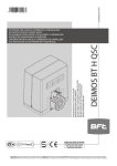
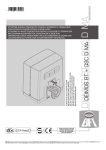
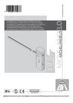
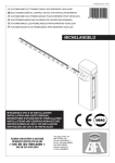
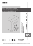
D811472 00100_01 29-10-09
RIGEL
RIGEL 5 5
ISTRUZIONI D’USO E DI INSTALLAZIONE
INSTALLATION AND USER’S MANUAL
INSTRUCTIONS D’UTILISATION ET D’INSTALLATION
INSTALLATIONS-UND GEBRAUCHSANLEITUNG
INSTRUCCIONES DE USO Y DE INSTALACION
INSTALLATIEVOORSCHRIFTEN
CENTRALINA UNIVERSALE PER IL CONTROLLO DI UNO O DUE MOTORI
UNIVERSAL CONTROL UNIT FOR OPERATING ONE OR TWO MOTORS
UNITE DE COMMANDE UNIVERSELLE POUR LE CONTROLE D’UN OU DEUX MOTEURS
UNIVERSALSTEUERUNG FÜR EINEN ODER ZWEI MOTOREN
CENTRAL UNIVERSAL PARA EL CONTROL DE UNO O DOS MOTORES
CENTRAL UNIVERSAL PARA O CONTROLO DE UM OU DOIS MOTORES
Attenzione! Leggere attentamente le “Avvertenze” all’interno! Caution! Read “Warnings” inside carefully! Attention! Veuillez lire attentivement les Avertissements qui se trouvent à l’intérieur! Achtung! Bitte lesen Sie
aufmerksam die „Hinweise“ im Inneren! ¡Atención¡ Leer atentamente las “Advertencias” en el interior! Let op! Lees de “Waarschuwingen” aan de binnenkant zorgvuldig!
315 mA/T 230V
630 mA/T 110V
Connettore programmatore palmare,
Palmtop programmer connector,
Connecteur programmateur de poche,
Steckverbinder Palmtop-Programmierer,
Conector del programador de bolsillo,
Connector programmeerbare palmtop.
SSR5 (Fig. F)
ENGLISH
Display + tasti programmazione
Display + programming keys
Display + Programmierungstasten
Pantalla + botones programación
Display + programmeringstoetsen
1
2
3
4
Connettore scheda opzionale
Optional board connector
Connecteur carte facultative
Steckverbinder Zusatzkarte
Conector de la tarjeta opcional
Connector optionele kaart
5
6
7
6,3 A/F 230V
10 A/F 110V
Dip *?NCEE = OFF
Dip @JGLI = OFF
Dip DCSAJGEL= OFF
Dip @JGLI = OFF
Dip JSXGLR= OFF
Dip *?NCEE = ON
Dip @JGLI = ON
Dip DCSAJGEL= ON
Dip @JGLI = ON
Dip JSXGLR= ON
ESPAÑOL
B
0,5A max
(2A 2 sec.)
VSafe +
2
10 11 12 13
230V
150W
max.
VSafe -
10 11 12 13
DEUTSCH
1
FRANÇAIS
Connettore ricevitore radio
Radio receiver connector
Connecteur Récepteur Radio
Stecker Funkempfänger
Conector del receptor de radio
Connector Radio-ontvanger
220
20 21
5
1-PHOT
TX1
COM
BAR
PHOT
33 34 35 36 37
RX1
1
2
3
LOGICA test fotocellule OFF
Photocell test LOGIC OFF
LOGIQUE essai photocellules Désactivée
LOGIK Test Fotozellen OFF
LÓGICA prueba fotocélulas OFF
LOGICA test fotocellen OFF
4
5
RIGEL 5 -
3
NEDERLANDS
12
1
2
JP4
COM
JP3
24 V~
Collegamento di 1 coppia di fotocellule non verificate, Connection of 1 pair of non-tested
photocells, Connexion 1 paire photocellules non vérifiées, Anschluss von einem Paar nicht
überprüften Fotozellen, Conexión de 1 par fotocélulas no comprobadas, Aansluiting van 1 paar
fotocellen anders dan “trusted device”
24 V~
C
320
D811472 00100_01
ITALIANO
INSTALLAZIONE VELOCE-QUICK INSTALLATION-INSTALLATION RAPIDE
SCHNELLINSTALLATION-INSTALACIÓN RÁPIDA - SNELLE INSTALLATIE
A
D811472 00100_01
SYSTEM SETTINGS MENU
PRESET
Scroll up
AR
SR
AC
SC
ind
Scroll down
Automatic closing time (TCA)
40
20
40
30
40
40
Operation time motor 1
60
20
20
20
20
20
Confirm/Switch on display
Operation time motor 2
60
20
20
20
20
20
Pedestrian operation time
6
6
6
6
6
6
Opening delay time for leaf 1
3
2
2
2
2
2
Closing delay time for leaf 2
3
2
2
2
2
2
0
0
0
0
0
3
3
3
3
3
Exit Menù
hydraulic
Slow-down time
x1
electromechanical
'2
15
15
15
15
15
15
Preheating
30
30
30
30
30
30
99
99
99
99
99
50
50
50
50
50
99
99
99
99
99
50
hydraulic
Motor torque
DP?
0
Traffic-light area clearance time
Slowdown motor hydraulic
torque
electromechanical
J?LES?EC
DEFAULT
Parameter
electromechanical
40
40
50
50
50
50
Braking
0
0
0
0
0
0
Emergency braking
60
60
60
60
60
60
Zona
0
0
0
0
0
0
LOGIC
BCS
CLE
CQN
RWNC
FWBP
CJCA
LMR
FWBP: hydraulic operator
CJCA: electromechanical operator
NPCQCR
0
QP
C PCMRCQ
?P: automatic operation, residential
QP: semiautomatic operation, residential
?A: automatic operation, commercial
QA
1A: semiautomatic operation, commercial
FGBBCL@SRRML
OFF
ON
OFF
ON
OFF
OFF
Opening Impulse lock
OFF
OFF
OFF
ON
ON
OFF
Impulse lock TCA
OFF
OFF
OFF
OFF
OFF
OFF
Impulse lock on closing
OFF
OFF
OFF
OFF
OFF
OFF
Ram blow on opening
OFF
OFF
OFF
OFF
OFF
OFF
Ram blow in closing
OFF
OFF
OFF
OFF
OFF
OFF
2-step logic
OFF
OFF
OFF
OFF
OFF
OFF
3-step logic
OFF
ON
OFF
ON
OFF
OFF
Pre alarm
OFF
OFF
OFF
ON
ON
OFF
Lock hold
hydraulic
electromechanical
OFF
ON
ON
ON
ON
ON
OFF
OFF
OFF
OFF
OFF
Hold-to-run
OFF
OFF
OFF
OFF
OFF
ON
Photocells on opening
OFF
ON
ON
ON
ON
OFF
Rapid closing
OFF
OFF
OFF
OFF
OFF
OFF
Photocell test
OFF
OFF
OFF
OFF
OFF
OFF
Electric edge test
OFF
OFF
OFF
OFF
OFF
OFF
Photocell test on opening
OFF
OFF
OFF
OFF
OFF
OFF
Photocell test on closing
OFF
OFF
OFF
OFF
OFF
OFF
Master/Slave
OFF
OFF
OFF
OFF
OFF
OFF
Fixed code
OFF
OFF
OFF
OFF
OFF
OFF
Radio transmitter programming
ON
ON
ON
ON
ON
OFF
OFF
OFF
OFF
OFF
OFF
ON
ON
ON
ON
ON
Time count
?A
GLB
Automatic Closing
hydraulic
electromechanical
OFF
Courtesy light
OFF
OFF
OFF
OFF
OFF
OFF
Clock / Pedestrian
OFF
OFF
OFF
OFF
OFF
OFF
Light/Alarm
OFF
OFF
OFF
OFF
OFF
OFF
1 Active motor
OFF
-----
-----
-----
-----
-----
Gate-open or 2nd radio channel warning
light
OFF
OFF
OFF
OFF
OFF
OFF
Safety edge
ON
ON
ON
ON
ON
ON
Blinking output
OFF
OFF
OFF
OFF
OFF
OFF
Type of lock
OFF
OFF
OFF
OFF
OFF
OFF
'LB: dead man operation
PCJC?QC
BCQGBCPCB@SRRML
-
CLB
RIGEL 5 -
5
JP5
52 53 54 55 56
44 45 46 47 48 49 50
A1
B1
C1
1
2
TX1
RX1
1-PHOT
44
20
21
20
33
5
35
1
2
3
21
20
33
53
35
4
1
2
TX1
RX1
1-PHOT
4
5
B2
1
2
TX1
RX1
2-PHOT
44
20
1
2
TX2
RX2
1
2
3
4
5
1
2
3
4
5
21
20
6
5
4
3
2
1 Bar 1
44
37
33
6
5
4
3
2
1 Bar 1
C2
1-BAR
44
20
1
2
TX1
RX1
3-PHOT
44
20
44
20
44
20
1
2
1
2
1
2
TX2
TX3
TX1
RX2
RX3
RX1
4-PHOT
44
20
44
20
44
20
1
2
1
2
1
2
RIGEL 5
TX2
TX3
TX4
RX2
RX3
RX4
44
33
54
53
33
1
2
3
4
5
21
20
1
2
3
4
5
21
20
1
2
3
4
5
21
20
47
53
33
1
2
3
4
5
21
20
1
2
3
4
5
21
20
1
2
3
4
5
21
20
47
49
48
1
2
3
4
5
21
20
50
53
33
33
35
46
45
33
35
46
45
20
21
20
21
44
33
54
20
21
44
45
46
20
21
RX1
1
2
3
21
20
33
5
55
1
2
3
21
20
33
56
55
4
1
2
TX1
RX1
1-PHOT
4
6
5
4
3
2
1 Bar 2
6
5
4
3
2
1 Bar 1
3-BAR
6
5
4
3
2
1 Bar 2
44
33
54
47
20
21
6
5
4
3
2
1 Bar 3
44
20
6
5
4
3
2
1 Bar 2
TX1
RX1
44
48
49
47
20
21
44
33
54
50
20
21
1
2
TX2
RX2
44
20
1
2
TX1
RX1
3-PHOT
44
20
1
2
TX2
44
20
1
2
TX3
44
20
1
2
TX1
RX2
RX3
RX1
4-PHOT
6
5
4
3
2
1 Bar 3
6
5
4
3
2
1 Bar 4
1
2
3
4
5
21
20
1
2
3
4
5
21
20
1
2
3
4
5
21
20
1
2
3
4
5
21
20
1
2
3
4
5
21
20
47
56
53
1
2
3
4
5
21
20
1
2
3
4
5
21
20
46
45
1
2
3
4
5
21
20
47
49
48
1
2
3
4
5
21
20
50
56
33
33
55
56
33
C4
C5
6
5
4
3
2
1 Bar 1
1
2
2-PHOT
4-BAR
20
21
44
20
44
20
B5
44
37
33
TX1
5
B4
44
37
33
1
2
1-PHOT
2-BAR
21
20
A4
21
20
C3
20
21
33
35
TEST PHOT = ON
44
20
10 -
44
37
54
33
20
21
1-BAR
B3
A3
A5
33
20
21
6
5
4
3
2
1 Bar 1
37
TEST BAR = ON
A2
1
2
3
44
20
1
2
TX2
RX2
44
20
1
2
TX3
RX3
44
20
1
2
TX4
RX4
33
55
46
45
33
55
TEST PHOT CLOSE = ON
21
20
TEST PHOT CLOSE=OFF
FOTOCELLULE IN CHIUSURA, PHOTOCELLS, PHOTOCELLULES, FOTOZELLEN, FOTOCÉLULAS, FOTOCELLEN
TEST BAR=OFF
COSTE / FOTOCELLULE IN APERTURA, COSTE /
FOTOCELLULE IN APERTURA, COSTE / FOTOCELLULE IN APERTURA, COSTE / FOTOCELLULE IN
APERTURA, COSTE / FOTOCELLULE IN APERTURA,
COSTE / FOTOCELLULE IN APERTURA.
TEST PHOT=OFF
FOTOCELLULE, PHOTOCELLS, PHOTOCELLULES,
FOTOZELLEN, FOTOCÉLULAS, FOTOCELLEN
D811472 00100_01
24 VTX
FLT CL
FLT BAR
PHOT CL
FLT PHOT
JP6
33 34 35 36 37
COM
COM
BAR
PHOT
JP4
20 21
COM
24 V~
24 V~
JP3
D
D1
Fotocellule,
Photocells, Coste / Fotocellule in Apertura, Coste / Fotocellule in Apertura, Coste / Fotocellule in Chiusura, Fotocellule in Chiusura, FoPhotocellules, Fotozellen, Fotocellule in Apertura, Coste / Fotocellule in Apertura, Coste / Fotocel- tocellule in Chiusura, Fotocellule in Chiusura, Fotocellule in Chiusura, Fotocellule in Chiusura.
lule in Apertura, Coste / Fotocellule in Apertura,
Fotocellulas, Fotocellen.
A1
B4
C5
A1
B5
C4, C5
A2
B4
C5
A2
B5
C4, C5
A3
B4
C5
A3
B5
C4, C5
A4
B1
C5
A4
B2
C5
A4
B3
C5
A4
B4
C4, C5
A4
B5
C1, C2, C3, C4, C5
A5
B1
C4, C5
A5
B2
C4, C5
A5
B3
C4, C5
A5
B4
C1, C2, C3, C4, C5
A5
B5
C1, C2, C3, C4, C5
E
RX2
TX1
RX2
RX1
TX2
TX1
RX2
RX1
TX2
RX1
SCS1
SCS1
TX2
SCS1
TX1
D811472 00100_01
Combinazioni non possibili, Not possible combinations, Combinaisons non possibiles, Nicht mogliche kombinationen,
Combinaciones no posibles, Combinaties niet mogelijk.
Max. 250m
F
UNIDA
Programmeerbare Universele Palmtop
RIGEL 5 -
11
Scroll up
Scroll down
Confirm/Switch on display
x2
Exit Menù
N?P?K
See PARAMETERS MENU
N?P?K
CLB
N?P?K
JMEGA
JMEGA
See LOGIC MENU
JMEGA
CLB
JMEGA
P?BGM
?BBQR?PR
FGBBCL@SRRML
PCJC?QC
BCQGPCB@SRRML
MI
BBAF
FGBBCL@SRRML
PCJC?QC
BCQGPCB@SRRML
MI
CP?QC
.0%
!-"06
!
CLB
+/OK
$"
OK
OK
T
'2
J?LES?EC
OK
DIAGNOSTICS and WARNINGS
- +
$0
DIAGNOSTICS
DESCRIPTION
CODE
EXTERNAL START input activation
stre
INTERNAL START input activation
stri
input activation PEDESTRIAN
ped
OK
- +
CLB
"#3
OK
- +
#,%
OK
- +
CQN
OK
.0%
BCD?SJR
CLB
open
OPEN input activation
cls
stop
phot
phop
phcl
bar
CLOSE input activation
STOP input activation
PHOT input activation
activation of input for PHOTOCELL ON OPENING
activation of input for PHOTOCELL ON CLOSING
input activation SAFETY EDGE
activation of input for MOTOR 1 CLOSING LIMIT
SWITCH
activation of input for MOTOR 1 OPENING
LIMIT SWITCH
activation of input for MOTOR 2 CLOSING LIMIT
SWITCH
activation of input for MOTOR 2 OPENING
LIMIT SWITCH
svc1
QR?R
OK
TCPQ
OK
@DRPGECJ
+/- +
CLB
LAWAJCQ
OK
+/-
- +
L0CKMRCQ
OK
+/-
svo1
svc2
svo2
ti e
TIMER input activation
Er01
photocell test anomaly
check photocell connection and/or
parameter/logic settings
Er02
safety edge test anomaly
check safety edge connection and/or
parameter/logic settings
er03
photocell on opening test anomaly
check photocell connection and/or
parameter/logic settings
er04
photocell on closing test anomaly
check photocell connection and/or
parameter/logic settings
hardware anomaly
check connections to motor
Er1X *
* X = 0,1,…,9,A,B,C,D,E,F
18 -
RIGEL 5
NOTES
D811472 00100_01
ACCESS TO MENUS Fig. 1
D811472 00100_01
GENERAL WARNINGS
WARNING! Important safety instructions. Carefully read and comply with
the Warnings booklet and Instruction booklet that come with the product as
incorrect installation can cause injury to people and animals and damage to
property. They contain important information regarding safety, installation,
use and maintenance. Keep hold of instructions so that you can attach them
to the technical file and keep them handy for future reference.
MAINTENANCE
- Dismantle the gearmotor and replace the lubricating grease every two
years.
- When any operational malfunction is found, and not resolved, disconnect the mains power supply and request the assistance of a specialised
technician (installer).
SCRAPPING
Materials must be disposed of in conformity with the current regulations.
In case of scrapping, the automation devices do not entail any particular
risks or danger. In case of recovered materials, these should be sorted out
by type (electrical components, copper, aluminium, plastic etc.).
DISMANTLING
When the automation system is disassembled to be reassembled on another
site, proceed as follows:
- Disconnect the power supply and the entire electrical installation.
- Remove the actuator from its fixing base.
- Disassemble all the installation components.
- In the case where some of the components cannot be removed or are
damaged, they must be replaced.
Correct controller operation is only ensured when the data contained in
the present manual are observed. The Company is not to be held responsible for any damage resulting from failure to observe the installation
standards and the instructions contained in the present manual.
The descriptions and illustrations contained in the present manual are
not binding. The Company reserves the right to make any alterations
deemed appropriate for the technical, manufacturing and commercial
improvement of the product, while leaving the essential product features unchanged, at any time and without undertaking to update the
present publication.
Warning! For connection to the mains power supply, use a multicore
cable with a cross-section of at least 4x1.5mm2 of the kind provided for
by the regulations mentioned above (by way of example, type H05 VV-F
cable can be used with a cross-section of 4x1.5mm2). To connect auxiliary
equipment, use wires with a cross-section of at least 0,75 mm2.
Have an omnipolar circuit breaker installed with a contact separation
of at least 3 mm and featuring overload protection, suitable for cutting
the automated device off from the mains.
Only use pushbuttons with a capacity of 10A-250V or more.
The cables must be held in position using an extra fixing device in the
proximity of the terminals, e.g. with cable clamps.
Also add more clips to the limit device wires, to the transformer primary
or secondary wires, and to the wires connected to the printed circuit.
During installation, the power supply cable must be stripped in order
for the earthing wire to be connected to the appropriate terminal, but
the active wires must be left as short as possible. The earthing wire
must be the last to stretch in the case where the cable fixing device
becomes loose.
WARNING: extremely low safety voltage cables must be phisically
separated from low voltage cables. Access to the electrical compartment or to limit switches must be allowed to skilled personnel only.
Setting sensitivity incorrectly can result in damage to property and
injury to people and animals.
Compliance with current safety rules with regard to people, animals and
property must be assured at all times and, more specifically, measures must
be taken to avoid risks of injury due to crushing, in the area where the pinion
and rack mesh, and any other mechanical hazards. All critical points must
be protected by safety devices in accordance with the provisions of the
regulations in force.
RIGEL 5 -
19
ENGLISH
1) GENERAL SAFETY
WARNING! An incorrect installation or improper use of the product can
cause damage to persons, animals or things.
- The units making up the machine and its installation must meet the
requirements of the following European Directives: 2004/108/EEC, 2006/95/
EEC and later amendments. For all countries outside the EEC, it is advisable
to comply with the above-mentioned standards, in addition to any national
standards in force, to achieve a good level of safety.
- The Firm disclaims all responsibility resulting from improper use or any
use other than that for which the product has been designed, as indicated herein, as well as for failure to apply Good Practice in the construction of entry systems (doors, gates, etc.) and for deformation that could
occur during use.
- Make sure the stated temperature range is compatible with the site in
which the automated system is due to be installed.
- Do not install the product in an explosive atmosphere.
- Disconnect the electricity supply before performing any work on the system. Also disconnect buffer batteries, if any are connected.
- Have the automated system’s mains power supply fitted with a switch or
omnipolar thermal-magnetic circuit breaker with a contact separation of
at least 3.5 mm.
- Make sure that upline from the mains power supply there is a residual
current circuit breaker that trips at 0.03A.
- Make sure the earth system has been installed correctly: earth all the metal parts belonging to the entry system (doors, gates, etc.) and all parts of
the system featuring an earth terminal.
- Installation must be carried out using safety devices and controls that
meet standard EN 12978.
- Apply all safety devices (photocells, safety edges, etc.) required to keep
the area free of crushing, dragging and shearing hazards.
- Only use original spare parts for any maintenance or repair work. The
Firm disclaims all responsibility for the correct operation and safety of
the automated system if parts from other manufacturers are used.
- Do not make any modifications to the automated system’s components
unless explicitly authorized by the Firm.
- Dispose of packaging materials (plastic, cardboard, polystyrene, etc.) in
accordance with the provisions of the laws in force. Keep nylon bags and
polystyrene out of reach of children.
- Anything which is not expressly provided for in the present instructions,
is not allowed.
- The device is not meant to be used by people (including children) whose
physical, sensory or mental capacities are impaired or who do not have
suitable experience or knowledge, unless a person responsible for their
safety provides them with supervision or operating instructions.
CHECKING THE AUTOMATED DEVICE
Before the automated device is finally put into operation, perform the following checks meticulously:
• Make sure all components are fastened securely.
• Check the correct functioning of all safety devices (limit microswitches,
photocells, sensitive edges etc.).
• Make sure that the anti-crush system stops the door within the limits
provided for by the standards in force.
• Check the emergency operation control device.
• Check the opening and closing operations with the control devices in use.
• Check the standard and customised electronic functioning logic.
1) FOREWORD
The RIGEL 5 control unit is supplied by the manufacturer with standard
setting. Any modifications must be entered using the universal palmtop
programmer or the incorporated display. This Control unit supports the
entire EELINK protocol.
These are its main features:
- Control of one or two motors up to 600W power.
- Electronic torque setting.
- Adjustable electrodynamic braking.
- End-of-run speed slow-down.
- Separate opening / closing limit-switch inputs for each motor.
- Output for zone light.
- Separate inputs for safety devices.
- 12V output for click or suction-type electric lock.
- Output for timer piloting.
- Clock input.
- Connector for traffic-light board / motor preheating.
- Incorporated radio receiver.
The board is provided with a removable terminal board for easier maintenance
and replacement. This is supplied with a series of prewired jumpers to make
work easy for the installer.
The jumpers relate to the following terminals: 33-34, 35-36, 36-37, 38-39,
39-40, 41-42, 42-43, 52-55. If the above terminals are used, remove the
respective jumpers.
TERMINAL DESCRIPTION
1
2-3
4-5-6
5-14
Motor capacitor connection 1
7-8-9
Motor connection 2 (delayed closing), terminals 8-9 for motor
drive, terminal 7 common.
N.B. If only one motor is used, use motor output 2 and configure
logic “1 active motor”.
8-15
Motor capacitor connection 2.
10-11
12-13
2) TECHNICAL SPECIFICATIONS
CONTROL UNIT
Power supply
Mains/low voltage insulation
230V±10% 50Hz*
> 2MOhm 500V
Dielectric strength
Motor output current
mains/bty 3750V~ for 1 minute
1A+1A max (230V~) - 2A+2A max
(110V~)
Motor relay commutation current 10A
Zone/courtesy light
max 150W
Supply to accessories
24V~ (1A max absorption)
Electric lock
12V
(0.5A max, 2A for 3 s)
Light/alarm output with free n.o. max 3A 250V~
contact
Gate-open warning light
24V~ 3W max
Blinker
230V 40W max
Fuses
See Fig. A
Dimensions
See Fig. B
RECEIVER
Commands association
1st ch. = start
2nd ch. = relay 2nd ch. for 1 sec.
Built-in Rolling-Code radio-re- frequency 433.92MHz
ceiver
N° of combinations
4 billion
Max. n° of remotes that can be 63
memorized
Antenna impedance
50 Ohm (RG58)
(*) Special supply voltages to order.
Usable transmitter versions:
All ROLLING CODE transmitters compatible with
3) TUBE ARRANGEMENT Fig.A
Install the electrical system referring to the standards in force for electrical
systems CEI 64-8, IEC 364, harmonization document HD 384 and other
national standards.
---------------------------------------------------------4) TERMINAL BOARD WIRING Fig. A
Once suitable electric cables have been run through the raceways and the
automated device’s various components have been fastened at the predetermined points, the next step is to connect them as directed and illustrated
in the diagrams contained in the relevant instruction manuals. Connect the
live, neutral and earth wire (compulsory). The mains cable must be clamped
in the relevant cable gland, and the accessories’wires in the cable gland, while
the earth wire with the yellow/green-coloured sheath must be connected
in the relevant terminal.
20 -
RIGEL 5
GND terminal
230V~±10%, 50-60Hz power supply (2 neutral, 3 phase).
Motor connection 1 (delayed opening), terminals 5-6 for motor
drive, terminal 4 common.
16-17
230V~ output for blinker light (40W max) and EBP 230V modelelectric lock. WARNING! If the SSR5 auxiliary board is used
for motor preheating, move the connection to terminals 12-13
(Fig. A) and refer to LOGIC table “B” (Blinker output).
230V~ output for zone lighting (courtesy light dipswitch ON,
flashing light output dipswitch OFF)
230V~ output for courtesy light (courtesy light dipswitch OFF,
flashing light output dipswitch OFF)
230V~ output for flashing light output (flashing light dipswitch
ON)
Stair-light output (N.O.) (dip Light/alarm = OFF) Only connect
these terminals to safety extra low voltage (SELV) circuits suitably
insulated from live parts.
Light/alarm output (N.O.) (dip Light/alarm = ON). Only connect
these terminals to safety extra low voltage (SELV) circuits suitably
insulated from live parts.
N.O. output for 2nd radio channel (SCA dipswitch - 2ch =
OFF)
18-19 N.O. output for gate open warning light. This warning light is off
when the gate is closed, flashes as it is closing and remains on
when the gate is open or opening. (dipswitch SCA - 2ch = ON)
20-21 24V~ output (1A max.) to power accessories.
20-44 24V~ output to power VSAFE
solenoid latch output (lock type dipswitch = OFF)
12V
22-23
solenoid sucker output (lock type dipswitch = ON)
12V
24-25 Antenna input for radio receiver board (24 signal, 25 braid).
Internal Start Pushbutton (n.o.). Internal Start command
26-27
for traffic light.
Start Pushbutton (n.o.). Parallel to radio receiver relay (CH1).
27-28
External Start command for traffic light.
Pedestrian pushbutton (n.o.). Activation takes place on
motor 2; moreover, if the opening cycle has started (not from
27-29
pedestrian pushbutton), the pedestrian control has the same
effect as a Start command.
30-31 Open Pushbutton (n.o.).
30-32 Close Pushbutton (n.o.).
Lock pushbutton (n.c.). If not used, leave the jumper con33-34
nected.
Photocell contact input PHOT (n.c.). If not used, leave jumpers
35-36
inserted.
Photocell contact input PHOT OPENING (N.C.). If not used, leave
jumpers inserted. (dipswitch BAR = OFF)
36-37 BAR safety edge input (n.c.) If intervenes during opening, it
stops and we have partial closure. If not used, leave jumpers
inserted. (dipswitch BAR = ON)
Opening limit switch for motor 1 SWO1 (n.c.). If not used, leave
38-39
the jumper connected.
Closing limit switch for motor 1 SWC1 (n.c.). If not used, leave
39-40
the jumper connected.
Opening limit switch for motor 2 SWO2 (n.c.). If not used, leave
41-42
the jumper connected.
Closing limit switch for motor 2 SWC2 (n.c.). If not used, leave
42-43
the jumper connected.
20-44 24V output for transmitters.
45-46-47 Connection with tested safety devices (see Fig. D)
48-49-50 Connection with tested safety devices (see Fig. D)
D811472 00100_01
INSTALLATION MANUAL
D811472 00100_01
INSTALLATION MANUAL
51-52
52-55
53
54
56
JP7
JP8
JP9
Clock input (n.o.). If the connected contact is open (n.o.), the
leaves close and get ready for normal operation. If the contact
is closed (n.c.), the leaves open and stay open until the contact
reopens. If the opening movement controlled by the TIMER is
prevented by the safety devices, gate opening can be resumed
by activating the START/OPEN control.
Input for photocelledge contact on closing SAFE CL (n.c.). In
case of activation during closing, the gate is stopped and partly
reopened. If not used, leave the jumper connected.
Photocell test input (PHOT-FAULT).
Safety edge/opening photocell test input (BAR-FAULT).
Closing photocell test input (PHOT CL-FAULT).
Radio receiver board connector.
Optional card connector (SCS)
Traffic-light / Preheating SSR5 board connector.
9) SSR5 TRAFFIC-LIGHT / MOTOR PREHEATING BOARD
When inserted in the appropriate connector, it provides:
- Control of two traffic lights with 2 lights each.
- Preheating of motors for cold climate.
Refer to specific manual.
9.1) Traffic light layout
Traffic light 1 must be positioned on the outside of the gate and traffic light
2 on the inside.
WARNINGS - Place signs for speed limitation to “Walking pace”.
9.2) Motor preheating layout
The “S” probe must be positioned and fixed on the outside to detect external temperature. It is to be connected to respective terminals 7-8 on the
preheating board.
WARNINGS - Move the EBP solenoid lock and flashing light to 12-13. (Fig.
A Ref. 2)
WARNINGS - Set flashing light dipswitch = ON
5) CONNECTION WITH EXPANSION BOARDS AND UNIVERSAL HANDHELD
PROGRAMMER (Fig. A)
Refer to specific manual.
6) SAFETY DEVICES
Note: only use receiving safety devices with free changeover contact.
6.1) TESTED DEVICES (Fig. D)
6.2) NON-TESTED DEVICES (Fig. C - D)
7) CALLING UP MENUS: FIG. 1
7.1) PARAMETERS MENU (PARA ) (PARAMETERS table “A”)
7.2) LOGIC MENU (LOGIC) (LOGIC table “B”)
7.3) RADIO MENU (radio) (Radio table “C”)
- IMPORTANT NOTE: THE FIRST TRANSMITTER MEMORIZED MUST BE
IDENTIFIED BY ATTACHING THE KEY LABEL (MASTER).
In the event of manual programming, the first transmitter assigns the RECEIVER’S KEY CODE: this code is required to subsequently clone the radio
transmitters.
The Clonix built-in on-board receiver also has a number of important advanced features:
• Cloning of master transmitter (rolling code or fixed code).
• Cloning to replace transmitters already entered in receiver.
• Transmitter database management.
• Receiver community management.
To use these advanced features, refer to the universal handheld programmer’s
instructions and to the general receiver programming guide.
7.4) LANGUAGE MENU (language)
Used to set the programmer’s language on the display.
7.5) DEFAULT MENU (default)
Restores the controller’s DEFAULT factory settings.
8) SCS OPTIONAL MODULES
8.1) SERIAL CONNECTION USING SCS1 BOARD (Fig. A - E)
The RIGEL 5 control panel allows several automation units (SCS1) to be
connected in a centralised way by means of appropriate serial inputs and
outputs. This makes it possible to use one single command to open and close
all the automation units connected.
Following the diagram in Fig. E, proceed to connecting all the RIGEL 5 control
panels, exclusively using a telephone-type line.
Should a telephone cable with more than one pair be needed, it is indispensable to use wires from the same pair.
The length of the telephone cable between one appliance and the next
must not exceed 250 m.
At this point, each of the RIGEL 5 control panels must be appropriately
configured, by setting a MASTER unit first of all, which will have control over
all the others, to be necessarily set as SLAVE (see logic menu).
Also set the Zone number (see parameter menu) between 0 and 127.
The zone number allows you to create groups of automation units, each
one answering to the Zone Master unit. Each zone can only be assigned
one Master unit, the Master unit in zone 0 also controls the Slave units
in the other zones.
8.2) Interface with WIEGAND systems via SCS-WIE module.
Refer to the SCS-WIE module’s instructions.
RIGEL 5 -
21
10.1) TABLE A: PARAMETERS MENU (PARA )
Parameter
min.
TCA
3 sec. 120 sec.
40
vork. t.
ot.1
vork. t.
ot.2
ped. t.
open delay
ti e
cls delay
ti e
3 sec. 180 sec.
60
3 sec. 180 sec.
60
3 sec.
9 sec.
6
0 sec.
10 sec.
3
0 sec.
60 sec.
3
slov dovn t.
0 sec.
20 sec.
0
clear. t
0 sec.
30 sec.
15
preheat.
0%
99%
30%
slovd
torque
1%
99%
50%
1%
99%
50%
brake
0%
99%
0%
e er. brake
0%
99%
60%
0
127
0
ot. torque
Zone
max.
default personal Definition
Description
Set the numerical value of the TCA automatic closing time from 3 to 120
Automatic Closing Time
seconds.
Enter the numerical value corresponding to the working time from 3 to 180
Operation time motor 1
seconds for motor 1.
Enter the numerical value corresponding to the working time from 3 to 180
Operation time motor 2
seconds for motor 2.
Set the pedestrian opening time of motor 2 from 3 to 90 seconds.
Pedestrian operation time
Set the opening delay time for motor 1 with respect to motor 2, which can
Opening delay time for leaf 1
be adjusted from 0 to 10 seconds.
Set the closing delay time for motor 2, which can be adjusted from 0 to
Closing delay time for leaf 2
60 seconds.
Set the slow-down to approach time from 0 to 20 seconds. The slow-down
time is subtracted from the work time.
NOTE: it is advised to activate timing.
Slow-down time
NOTE: only use this function when limit switches are fitted.
NOTE: Do not use with hydraulic motors.
Traffic-light area clearance Set the required clearance time for the area involved in the traffic governed
time
by traffic light, from 0 to 30 seconds. Set to 0 if not used.
Set the percentage value of the current from 0 (deactivated pre-heating) to
99% which can be made to pass through the motor windings to keep them
Preheating
at the right temperature.
NOTE: Only with SSR5.
Set numerically from 1% to 99% the value of motor torque during slowdown
Slowdown Motor Torque
time.
Set the numerical torque value from 1 to 99%.
Motor torque
NOTE: When using with oil-hydraulic motors, it is necessary to set the
torque value to 99% and adjust the force directly on the motor.
Set the braking value from 0% (min.) to 99% (max.) according to the gate
Braking
weight and the mechanical demands involved.
Set the value of the emergency braking from 0% (min.) to 99% (max.). This
Emergency braking
is carried out by enabling the safety commands on the inputs 34 (block),
37 (SAFE OP) and 55 (SAFE CL).
Enter the zone number between 0 (minimum value) and 127 (maximum
Zona
value). See paragraph “SCS OPTIONAL MODULES”.
10.2) TABLE B: LOGIC MENU (logic)
Logic
Cross out
setting
used
ON
Automatic
Closing Time
OFF
ON
Opening Impulse lock
OFF
ON
I mpulse lo ck
TCA
OFF
ON
Impulse lock on
closing
OFF
Default Definition
TCA
OFF
Ibl open
OFF
ibl TCA
OFF
bl close
OFF
ra blov
c.op
OFF
Ram blow on
opening
OFF
R a m b l ow i n
closing
2 step
OFF
2-step, 4-step
logic
3 step
OFF
3-step logic
pre-alar
OFF
Pre alarm
OFF
Lock hold
ra blov
c.cl
bloc
persist
ON
OFF
ON
OFF
ON
OFF
ON
OFF
ON
OFF
ON
OFF
hold-torun
22 -
RIGEL 5
OFF
Hold-to-run
ON
OFF
Description
Switches automatic closing on.
Switches automatic closing off.
The Start impulse has no effect during the opening phase.
The Start impulse becomes effective during the opening phase.
The Start impulse has no effect during the TCA dwell period.
The Start impulse becomes effective during the TCA dwell period.
The start impulse has no effect during the closing stage.
The start impulse is effective during the closing stage.
It pushes for approx. 2 seconds in closing direction before opening. This allows the electric lock to be released
more easily (not affected by limit switches). IMPORTANT - When no adequate mechanical backstops are
installed, do not use this function. It is also to be absolutely avoided in the automation of sliding gates.
Excludes the ram blow in closing.
Before carrying out the closing manoeuvre, the gate pushes for about 2 seconds on opening. This allows the
electric lock to be released more easily.(not affected by limit switches)
IMPORTANT - When no adequate mechanical backstops are installed, do not use this function. It is also to be
absolutely avoided in the automation of sliding gates.
Excludes the ram blow in closing.
Enables 2-step logic (prevails over “3-step logic”).
A start impulse has the following effects:
Enables 4-step logic when the 3-step logic is set to OFF.
2 step
3 step
4 step
Enables 3-step logic (with 2 steps=OFF).
closed
opens
opens
opens
Disables 3-step logic.
on closing
stop
The blinker comes on about 3 seconds before the motor
open
closes
closes
closes
starts.
on opening
stop + TCA stop + TCA
The blinker comes on at the same time as the motor
after stopping closes
opens
opens
starts.
If the motors remain still in a totally open or closed position for over one hour, they are activated for about 3
seconds in the respective direction. This operation takes place once every hour.
N.B.: This function has the purpose of compensating any oil volume decrease in the hydraulic motors, due to
a temperature drop during prolonged pauses, for instance at night, or to internal leaks.
IMPORTANT - When no adequate mechanical backstops are installed, do not use this function. It is also to be
absolutely avoided in the automation of sliding gates.
Exclude block maintenance.
Hold-to-run operation: the manoeuvre continues as long as the command key is kept pressed.
IMPORTANT - It is not possible to use the radio transmitter.
Impulse operation.
D811472 00100_01
INSTALLATION MANUAL
D811472 00100_01
INSTALLATION MANUAL
photc.
open
OFF
Photocells on
opening
fast cls
OFF
Rapid closing
test phot
OFF
Photocell test
test bar
OFF
Electric edge
test
test phot
op.
test phot
cl.
OFF
Photocell test
on opening
OFF
Photocell test
on closing
OFF
Master/Slave
OFF
Fixed code
ON
Radio transmitter programming
aster
fixed
code
radio
prog
ON
OFF
ON
OFF
ON
OFF
ON
OFF
ON
OFF
ON
OFF
ON
OFF
ON
OFF
ON
OFF
ti e. c.
OFF
Time count
zone
light
OFF
Courtesy light
clock ped
OFF
Clock / Pedestrian
lightalar
1
ot. on
sca-2ch
bar
ON
Light/Alarm
OFF
1 active motor
OFF
Gate-openor2nd
radio channel
warning light
ON
Safety edge
OFF
Blink ing output
OFF
Type of lock
ON
OFF
ON
OFF
ON
OFF
ON
OFF
ON
OFF
ON
OFF
ON
OFF
ON
blink
suctiontype
OFF
ON
OFF
In case of obscuring, this excludes photocell operation on opening. During the closing phase, it immediately reverses the motion.
In case of obscuring, the photocells are active both on opening and on closing. When a photocell is obscured
on closing, it reverses the motion only after the photocell is disengaged.
Closes the gate after photocell disengagement, before waiting for the end of the TCA (automatic closing time)
set.
Command not entered.
Activates photocell check (see Fig. D)
Deactivates photocell check
Activates electric edge check (see Fig. D)
Deactivates electric edge check
Enables the test of the active photocells on opening.
Desables the test of the active photocells on opening.
Enables the test of the active photocells on closing.
Desables the test of the active photocells on closing.
The control panel is set as Master in a centralised connection (see “SCS OPTIONAL MODULES”).
The control panel is set as Slave in a centralised connection (see “SCS OPTIONAL MODULES”).
The receiver is configured for operation in fixed-code mode.
The receiver is configured for operation in rolling-code mode.
This enables transmitter storage via radio:
1 – First press the hidden key (P1) and then the normal key (T1, T2, T3 or T4) of a transmitter already memorised
in standard mode by means of the radio menu.
2 – Within 10s press the hidden key (P1) and the normal key (T1, T2, T3 or T4) of a transmitter to be memorised.
The receiver exits the programming mode after 10s, other new transmitters can be entered before the end
of this time.
This mode does not require access to the control panel.
This disables transmitter storage via radio.
The transmitters can only be memorised using the appropriate Radio menu.
Clones and replays are not accepted.
The control unit calculates the activation time of each motor, based on the preceding manoeuvres.
The control unit activates the motors at each manoeuvre for the time set. N.B. Always set the operation time to a
slightly higher value than needed to carry out the complete manoeuvre.
Zone light. Remains active as long as the manoeuvre lasts.
Courtesy light. Remains active for 90 seconds after last operation.
N.B. These settings cannot be used if the blinker output is set to ON.
Input for the connection of an external timer.
The Clock input is only active in Motor 2, for the pedestrian time set.
A start command given during the clock phase carries out complete gate opening and closing, resetting the
open pedestrian position.
The Clock input acts on both motors.
Gate-open alarm output (activated if the gate remains open for twice the TCA time set).
Stair-light control (the impulse stays on for 1 second).
Only motor 2 activated (1 leaf ).
Both motors are activated (2 leaves).
The output between terminals 18 and 19 is configured as Gate-open warning light, in this case the 2nd radio
channel controls pedestrian opening.
The output between terminals 18 and 19 is configured as 2nd radio channel.
Input of terminals 36-37 is active as input for the safety edge.
Input of terminals 36-37 is active as input for opening photocells.
Set the output at terminals 12-13 (“courtesy light”) as blinking output (active only during leaf movement). N.B.
Any setting relating to the “courtesy light” function is ignored.
Keep the output at terminals 12-13 as “courtesy light” or “zone light”.
WARNING! It is not possible to use the SSR5 board in motor preheating mode and at the same time have the
Zone light/Courtesy Light and Blinker/Electric lock on. In this case, outputs 10-11 cannot be used and outputs
12-13 can only be used for one of the two functions.
Suction-type lock. Enabled with gate closed.
Click lock. Enabled with a pulse at each opening.
10.3) TABLE C: RADIO MENU (RADIO)
Logic
Description
Add Start Key
Add start associates the desired key with the Start command.
Add 2ch Key
add 2ch associates the desired key with the 2nd radio channel command.
Erase List
erase 64 WARNING! Erases all memorized remote controls from the receiver’s memory.
Read receiver code
Displays receiver code required for cloning remote controls.
ON = Enables remote programming of cards via a previously memorized W LINK transmitter. It remains enabled for 3 minutes from the time the
W LINK remote control is last pressed.
OFF= W LINK programming disabled.
RIGEL 5 -
23