1
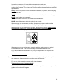
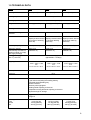
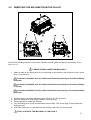
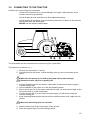
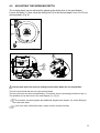
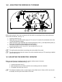
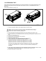
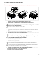
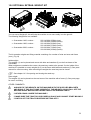
User manual and parts book Model: 1430-1830-2230 Serial nummer: Kwekerijweg 8 3709JA Zeist The Netherlands T: (31)306933227 F: (31)306933228 E: [email protected] www.redexim.com Translation of the original user manual NOTE: IN THE INTERESTS OF SAFETY AND ACHIEVING THE BEST RESULT, IT IS VERY IMPORTANT THAT THIS MANUAL IS READ CAREFULLY BEFORE USING THE OVESEEDER. 1526 English 922.120.300 UK FOREWORD Congratulations with the purchase of your Overseeder. To ensure long and safe use of this Overseeder, it is of major importance to all users to read and understand this user manual. Operation of this machine is not safe without full knowledge of the content of the manual. The Overseeder is not an independently operating machine. The user is responsible for using the appropriate tractor. The user must also check the tractor/Overseeder combination for safety aspects, such as noise level, adequate user instructions and any risks. The Overseeder is solely intended for use on lawns and other areas where grass could grow. On the next page you will first find the general safety instructions. Every user must know and apply them. After this, a registration card is included. This card should be returned for handling any future claims. This user manual offers many instructions numbered in sequence. This sequence should be observed. An indicates a safety instruction. An indicates a tip and/or note. All information and technical specifications provided at the moment that this document is published are the most recent ones. Design specifications may be changed without prior notice. This document is a translation of the original operating instructions. Upon request, the original operating instructions are available in Dutch. GUARANTEE CONDITIONS THIS OVERSEEDER COMES WITH A GUARANTEE FOR DEFECTIVE MATERIALS. THIS GUARANTEE IS VALID FOR A PERIOD OF 12 MONTHS FROM THE PURCHASING DATE. OVERSEEDER GUARANTEES ARE SUBJECT TO THE “GENERAL CONDITIONS FOR SUPPLY OF PLANT AND MACHINERY FOR EXPORT, NUMBER 188”, PUBLISHED UNDER THE AUSPICES OF THE UNITED NATIONS ECONOMIC COMMISSION FOR EUROPE. REGISTRATION CARD For your own information, please complete the table below: Serial number of machine Dealer name Purchasing date Remarks 2 ! Fig. 1 (1) SAFETY INSTRUCTIONS ! The design of the Overseeder allows for safe use. However, this is only possible if the user fully observes the safety instructions given in this manual. Read and understand (Fig. 1) the manual before starting to use the Overseeder. Not using the machine as described in the manual may lead to injury and/or damage to the Overseeder. The Overseeder is solely intended for tilling lawns or areas where grass should grow. Any other use is considered to be incorrect use. The manufacturer does not accept any liability with regard to damage resulting from incorrect use; all resulting risks are the responsibility of the user. Correct use also includes following the manufacturer’s instructions for use, maintenance and repair. Before using the Overseeder, inspect the area to be treated. Remove any loose obstacles and avoid irregularities. (2) The Overseeder was constructed according to the latest technological knowledge and is safe to use. Improper use, maintenance or repair of the machine may result in injury to both the user and others. This should be avoided! Always use the Overseeder in combination with the appropriate tractor as described in the technical data. (3) All persons whom the owner assigns to operate, maintain or repair the Overseeder must read and completely understand the operating manual and in particular the Safety Instructions section. The user is responsible for a safe tractor/Overseeder combination. This unit must be tested in terms of noise, safety and ease-of-use. In addition, user’s instructions must be prepared. (4) Before using the Overseeder, the user is obliged to inspect it for visible damage and defects. Any changes of the Overseeder (including its functioning) that may affect its safety must be corrected immediately. For safety reasons it is in principle forbidden to make changes in or additions to the Overseeder (with the exception of those approved by the manufacturer). If any modifications have been made to the Overseeder, the present CE certificate becomes null and void and the person who made the modifications should himself make sure a new CE certificate is granted. 3 Inspect the Overseeder for loose bolts/nuts/parts before each use. If present, inspect the hydraulic hoses regularly and replace them if they are damaged or show signs of wear. The replacement hoses must meet the manufacturer’s technical specifications. Always relieve the pressure from the hydraulic installation, if present, before carrying out any work on it. NEVER use de Overseeder when protective covers and safety stickers are missing. NEVER crawl under the Overseeder. Tilt the Overseeder if you need to have access to the bottom. NEVER step off the tractor while the engine is still running. When carrying out maintenance activities, adjustments or repairs make sure the Overseeder is locked to prevent it from sinking/riding/sliding away. When carrying out any maintenance activities, adjustments or repairs, always switch off the tractor engine first, remove the tractor key from the ignition and disconnect the PTO (Fig. 2). Fig 2 When carrying out any maintenance or repair activities, make sure to use original Overseeder parts only. This will ensure safety for the machine and its user. Only authorised technical personnel may carry out adjustments and repairs to the Overseeder. Keep an overview of repairs. (5) In addition to the instructions in this user manual, the generally applicable regulations with respect to safety and working conditions must be observed. For use on public roads the relevant traffic rules also apply. Transporting persons is not permitted! Do not use the Overseeder when it is dark, during heavy rain/storms or on slopes with a gradient of more than 20 degrees. 4 (6) Before starting to work, all persons operating the Overseeder must be familiar with all its functions and controls. Connect the Overseeder to the vehicle that will pull it exactly according to the instructions (Danger of injury!) Before driving off, make sure you have a clear view both nearby and far away. On both sides of the Overseeder, safety stickers (Fig. 3, 4, 5) have been applied to the sideboards and to the back cover (Fig. 6) showing these warnings. Make sure these safety stickers are always clearly visible and legible. Replace them if they are damaged. During operation, make sure there are NO persons in the danger area of the Overseeder to prevent them from getting injured by moving parts (Fig. 3). Fig 3 fig 4 Keep a distance of at least 4 metres! (Fig. 4) Be aware of the maximum lifting capacity of the towing vehicle. Wear suitable clothing. Wear sturdy shoes with a steel tip, wear long trousers, do up long hair and wear no loose clothing. (7) Location of safety stickers (Fig. 5). Fig. 5 5 EU-DECLARATION We, Redexim BV Utrechtseweg 127 3702 AC Zeist, the Netherlands declare entirely under our own responsibility that the product: OVERSEEDER WITH MACHINE NUMBER AS STATED ON THE MACHINE AND IN THIS MANUAL, to which this statement relates, is in accordance with the provisions of the Machine Directive 2006/42/EG. Zeist, 1-6-2015 A.C. Bos Manager Operations & Logistics Redexim Holland 6 CONTENTS FOREWORD 2 GUARANTEE CONDITIONS 2 REGISTRATION CARD 2 SAFETY INSTRUCTIONS 3 EU- DECLARATION 6 1.0 TECHNICAL DATA 8 2.0 REMOVING THE MACHINE FROM THE PALLET 9 3.0 CONNECTING TO TRACTOR 10 4.0 ADJUSTING THE WORKING DEPTH 11 5.0 SETTING THE SEED QUANTITY. 12 6.0 TRANSPORTING THE OVERSEEDER 13 7.0 DRIVING SPEED 13 8.0 GENERAL REMARKS ON THE USE OF THE OVERSEEDER 13 9.0 OPERATING THE OVERSEEDER 13 10.0 START/STOP PROCEDURE 14 11.0 DISCONNECTING THE OVERSEEDER 15 12.0 TROUBLESHOOTING 15 13.0 MAINTENANCE 17 14.0 ADJUSTING THE SEEDING SLIT OPENING 18 14.1 ADJUSTING THE SEED-TRAY SCRAPER 18 14.2 SPREADING TEST 19 14.3 OPEN AND CLOSE THE TOP UNIT 20 15.0 OPTIONAL EXTRAS: WEIGHT KIT 21 16.0 OPTIONAL EXTRAS: BOGY KIT 22 7 1.0 TECHNICAL DATA Model 1430 1830 2230 Working width 1.38 m (54.3”) 1.80 m (70.9”) 2.22 m (87.4”) Working depth 5mm-20mm (0.19”-0.78”) Seeding speed Up to. 12 Km/h (7.5 mph) Weight 1416Kg (3115 lbs) 1750Kg (3850 lbs) Seeding row distance 2076 Kg (4567 lbs) 30 mm (1.2”) Number of cutting elements 47 61 75 Recommended tractor 40 HP with minimal lift capacity 610mm behind the lift eyes of 3000 Kg (6614 lbs) 50 HP with minimal lift capacity 610mm behind the lift eyes 3600 Kg (7937 lbs) 60 HP with minimal lift capacity 610mm behind the lift eyes 4450 Kg (9810 lbs) Seed-tray capacity 230ltr. (8.1cu. ft.) 300ltr. (10.6cu. ft.) 360ltr. (12.7cu. Ft.) Maximum capacity (theoretically at maximum speed ±12 km/h (7.5 mph) and single passage) Seeding density per 100 m2 (1076.4 ft2) 16920 m2/h (182125 ft2/h) 21960 m2/h (236375 ft2/h) 27000 m2/h (290626 ft2/h) Shipping dimensions Normal seed: 0.4 – 5.7 Kg (0.88 - 12.57 lbs) (adjustable in 10 steps) LxWxH 1310 x 1724 x 1160 mm 51.6” x 67.9” x 45.7” Three-point connection LxWxH 1310 x 2144 x 1160 mm 51.6” x 84.4” x 45.7” 3-punt CAT. 2 Lubricant EP 2 Standard parts Fillable back roller with scraper. 5 gear sets for adjusting the seeding density. Integrated seed spreading tray. Manual container. Seed tray with sight-glass. Seeding wheel adjusting to the area. Independent cutting elements adjusting to the area. Adjustment legs for storage. Optional extras Bogy kit Weight kit Ballast gewicht: Front Center rear LxWxH 1310 x 2564 x 1165 mm 51.6” x 100.9” x 45.7” 44 Kg (97 lbs) 148 Kg (326 lbs) 352 Kg (774 lbs) 79 Kg (174 lbs) 193 Kg (425 lbs) 563 Kg (1239 lbs) 114 Kg ( lbs) 238 Kg (524 lbs) 733 Kg (1612 lbs) 8 2.0 REMOVING THE MACHINE FROM THE PALLET Fig. 6 Perform the following actions to remove the machine from the pallet and place it horizontally on the floor (see Fig.6): !! NEVER CRAWL UNDER THE MACHINE !! 1. Attach a cable to the lifting points (2) on both sides of the machine, and to the top of the 3-point hitch (1) on the front. Overseeder 1430 Make sure the cable/crane/lift has the capacity to lift at least 2800 kg (6160 lbs). Overseeder 1830 Make sure the cable/crane/lift has the capacity to lift at least 3500 kg (7700 lbs) . Overseeder 2230 Make sure the cable/crane/lift has the capacity to lift at least 4150 kg (9130 lbs) . 2. 3. 4. 5. Lift the machine, including the pallet, about 100 mm (4”) off the ground. Remove the pallet by removing the bottom 3-point pins (4). Pull the pallet from under the machine. Turn de locking pins (4) half a rotation and remove them. Pull out the legs (5) and replace the locking pins(4). 6. Lower the machine in a controlled and slow fashion until it is fully on the ground. !! STAY CLEAR OF THE MACHINE, IT CAN SLIDE !! 9 3.0 CONNECTING TO THE TRACTOR Checks prior to connecting the Overseeder. Check the Overseeder for any visual damage, and repair if safe operation of the machine cannot be guaranteed. Check whether all nuts and bolts have been tightened properly. Check whether all protective covers and safety stickers are in place on the machine, and whether they are undamaged. NEVER use the machine without them. Fig.7 The Overseeder can be connected to the tractor using the 3-point hitch. The method is as follows: (Fig. 7) 1. Remove the 3-point pins (1 and 2). 2. Carefully back up the tractor, so that the lifting arms (4) can be connected to the frame. !! Make sure the tractor is secured in place and cannot start moving!! !! Switch the tractor off prior to getting off!! 3. Connect the lifting arms to the bottom 3-point pins (2) and secure them using the included locking pins. 4. Set the stabiliser of the tractor to a 100 mm sideways stroke. 5. Mount the top link (3) of your tractor and extend it until it is at the same height as the top 3-point hitch (1) of the Overseeder. 6. Connect the top link (3) to the frame using the top pin (1) and secure using the included locking pin. 7. Keep extending/retracting the top link until the machine makes a 90° angle with the ground. !! Make sure all locking pins are secured!! 8. Start the tractor and lift the Overseeder off the ground. 9. Place the support legs (5) in the working position. 10 4.0 ADJUSTING THE WORKING DEPTH The working depth can be adjusted by adjusting the sliding foot of the seed blades. Loosen the bolts (1). Now move the sliding feet (2) to the desired depth, from 5 to 30 mm working depth. (Fig. 8) Fig.8 Fig. 9 !! Please note that front and rear sliding foot the same depth are set and parallel. The rear roller should also be set to the desired depth. The rear roller can also be mounted floating. This can be done by loosening pin and lock pin (1). The spindles (2) can be mount in the seed hopper (3). (Fig. 9) The machine can be equipped with additional weights.(see chapter 15), and/or filling the rear roller with water. If the rear roller is filled with water, empty it before it starts freezing. 11 5.0 SETTING THE SEED-QUANTITY The seed quantity can be set on the Overseeder by using various change gears. These provide various combinations for a broad range of settings (see Tab 1). The gears have been marked with a number given in Tab. 1; by changing the gears as indicated, the required quantity setting is obtained. The different combinations of gears have been installed in the seed tray. Fig. 10 Gear Option Bottom Top 25 95 40 80 45 75 52 68 Bentgrass Kentucky Bluegrass Ryegrass Kg/100m2 Lbs/1000ft2 Kg/100m2 Lbs/1000ft2 Kg/100m2 Lbs/1000ft2 0.20 0.40 0.20 0.40 0.30 0.60 0.40 0.80 0.35 0.70 0.55 1.10 0.45 0.80 0.40 0.80 0.65 1.30 0.60 1.20 0.50 1.00 0.85 1.75 58 62 0.70 1.40 0.60 1.20 1.00 2.00 62 58 0.80 1.60 0.75 1.50 1.20 2.45 68 52 1.00 2.00 0.90 1.80 1.40 2.80 75 45 1.30 2.60 1.10 2.20 1.90 3.85 80 40 1.50 3.00 1.40 2.80 2.20 4.45 95 25 2.80 5.70 2.60 5.30 4.15 8.40 Tab. 1 These quantities are determined with a slit distance of 0.3 mm between the seeding roller and the pressure plate (see section 14.0 for setting). In practice the quantities described in Tab. 1 may deviate to some extent due to other measuring/working conditions. In order to determine exactly the right seeding quantity for the seed used, it is recommended to carry out a spreading test (see section 14.2). 12 6.0 TRANSPORTING THE OVERSEEDER The user is responsible for the transport of the Overseeder behind the tractor when travelling on public roads. Check the national traffic rules. In view of the weight of the Overseeder, a maximum speed of 20 km/h (12.4 mph) should be observed while driving in open fields with the machine raised. Higher speeds may endanger the driver and/or other people and even damage the machine. Make sure the top link (3), see Fig. 7, is connected and tensioned in the conveyor. If this is not case, the machine could sustain serious damage. When the machine is lifted off the ground, at least 20% of the weight of the tractor must rest on the front axle. 7.0 DRIVING SPEED The driving speed is limited to 12 km/h (7.5 mph). Higher speeds are not recommended in view of excessive wear and damage that may occur to the machine due to, for example, rocks in the ground. 8.0 GENERAL REMARKS ON THE USE OF THE OVERSEEDER. Some general remarks/tips on the use of the Overseeder. A field can be tilled 2 or 3 times in different directions in order to obtain a higher seeding density and for seeding in a diamond shape. Do not make sharp turns, preferably drive in straight lines to avoid damaging the machine and/or the ground. When hitting a hard object in the soil, the cutting elements may be burred/damaged. Try to file burrs away or replace the cutting element. When the cutting elements become wet, the seed may stick and accumulate between the cutting elements. Make sure the cutting elements do not become wet or postpone the work. NEVER drive backwards while the running wheel is on the ground. 9.0 OPERATING THE OVERSEEDER Before using the Overseeder in the field, check the following: 1. Are there any loose objects in the field? Remove these first. 2. Are there any slopes? The maximum slope this machine can work on is 20 degrees. Always work downhill. 3. Does the ground contain hard objects? If so, use the Overseeder at a low speed and adjust the working depth. 4. Is there any danger of flying objects, such as golf balls, which may distract the attention of the driver? If so, do NOT use the Overseeder. 5. Is there any danger of sinking or sliding away? If so, postpone the work. 6. If the soil is frozen or very wet, the work should be postponed until the conditions are more favourable. 13 10.0 STARTING/STOPPING PROCEDURE Before starting the seeding, check the machine for the following points: While checking the machine/tractor combination must be fully locked to prevent it from driving/sliding/sinking away. The tractor engine must be switched off. Check the seeding elements for damage and repair if necessary. Check if the passage to the seeding elements is not blocked (e.g. funnels). Check if the machine is not wet or moist, in particular the seeding device. Check the seed spreading by rotating the running wheel 1 time (counterclockwise). Check if the drive is running smoothly. START SEEDING. The starting procedure is VERY important. If this procedure is not followed exactly as described below, serious damage may occur to the machine. The procedure is as follows: 1. Put the seed in the seed tray. 2. Set the required seed quantity using the change wheels (see section 5.0). 3. Drive to the place where you want to start. 4. Start with a driving speed of about 3 km/h (1.9 mph). 5. While driving lower the machine carefully and in a controlled way until the seeding elements are cutting the ground. While adjusting, the machine/tractor combination must be fully locked to prevent it from driving/sliding/sinking away. The tractor engine must be switched off. 6. Increase the speed until the correct driving speed has been reached. STOP SEEDING 1. Decrease the driving speed to about 3 km/h (1.9 mph). 2. While driving, raise the machine out of the ground. 3. Go to the following place and start again as described. It is absolutely imperative that the above procedures are followed. If the machine is placed in the ground while standing still, it may be seriously damaged. While driving, lower the machine CAREFULLY AND IN A CONTROLLED WAY during the lowering process. NEVER drive backwards when the running wheel is on the ground. 14 11.0 DISCONNECTING THE OVERSEEDER The machine can be disconnected from the tractor as follows: 1. Drive the Overseeder to a storage place with a stable/even floor. !! Make sure the tractor is secured in place and cannot start moving !! !! Switch the tractor off before getting off !! !! Be sure that the overseeder is stable on the floor and is locked against slipping before getting off the tractor !! 2. Turn the adjustable legs (see fig. 6 pos. 5) downwards and lock them using the locking pins included. 3. Slowly lower the machine until it stands on the ground. 4. Loosen the top rod and remove it. 5. Remove the lower arms from the tractor of the Overseeder. Make sure that the cutting elements do not touch the ground when storing the machine to avoid damage. 12.0 TROUBLESHOOTING Problem Seeding cuts are poorly shaped. Possible cause Solution Seeding discs are worn. Replace the seeding discs. Poor ground. Lower the working depth. Aerate/irrigate the ground if it is too dry and repeat the tilling later. Bearings of the seeding discs Replace the bearings. are worn. Seeding cuts are not closed. The seed is not in the seeding cut. Too much dead leaves and roots in the top layer of the field. Remove the dead leaves and roots.Increase the weight of the machine. Top rod incorrectly adjusted. Correctly adjust the rod. Seeding disks don’t turn / stuck Slits are too wide. Loosen the disks Ground is too hard. Aerate/irrigate the ground and repeat the tilling later. Rear roller not on the ground Worn seeding discs. Make it floating, see chapter 4 Replace the seeding discs. Wrong working depth. Adjust the machine to the correct working depth. Seeding pipes/funnels are blocked/dirty. Unblock/clean. Too wet conditions. Postpone the tilling. Lower the working depth. 15 Problem Seed is spoilt from the seed tray. Possible cause Seeding slit too large. Solution Readjust the seeding slit. Distance between the scraper Set the scraper closer to the seeding roller. and the seeding roller is too large. The machine does not reach the required depth. The adjustment plate of the seeding slit on the side is leaking. Tractor tensioning is too low. Tape up/glue. Put drawing arms into a higher hole. Ground is too hard. Aerate/irrigate. Top rod is incorrectly adjusted. Correctly adjust the top rod. Too much dead leaves and roots in the top layer of the field. Remove the dead leaves and roots. Not enough weight. Add weight. 16 13.0 MAINTENANCE Time schedule Check point/lubricating point Method Before each use Check for loose bolts/nuts. Tighten the loose bolts/nuts with the correct torque. Presence and legibility of safety Replace if damaged or stickers (Fig. 5). missing. After each use After first 20 operating hours (new or repaired) After every 100 operating hours. Clean the machine Clean the machine with compressed air. Don’t use water. Grease the roller bearings of the Use EP 2 lubricating rear roller. grease. Check for loose bolts/nuts. Tighten the loose bolts/nuts with the correct torque. Grease the drive chains. Use a chain spray. Grease the roller bearings of the Use EP 2 lubricating rear roller. grease. Check for loose bolts/nuts. Tighten the loose bolts/nuts with the correct torque. Grease the drive chains. Use a chain spray. Check the tension of the drive chains. Tension the tensioners of the drive chains. Check the seeding roller for dirt/damage. Clean the seeding roller or replace it if necessary. Check the seeding slit opening. Adjust the seeding slit if necessary. Check the seed quantity. Carry out a spreading test. Check the seeding pipes/funnels. Clean if necessary. Check the seeding elements for Repair or replace if damage. necessary. 17 14.0 ADJUSTING THE SEEDING SLIT OPENING Fig. 11 If the seed production does not correspond with the table, the seeding slit may need adjustment. This is done as follows: (see fig. 11) 1. Loosen all lock nuts (3). 2. Adjust bolt (4) such that a feeler gauge of 0.3 mm (0.01”) can be slit just between the roller (1) and the adjustment plate. 3. Check all bolts (4) and calibrate the slit opening between roller (1) and adjustment plate (2) along the entire width of the machine to 0.3 mm (0.01”). 4. Turn roller (1) half a turn and measure the slit opening. If necessary adjust it to 0.3 mm (0.01”) by turning bolt (4) in or out. 5. Tighten the lock nuts (3). The split opening should be equal along the entire width of the roller. The slit opening must have the same size as the smallest seed part. This opening is default set to 0.3mm (0.01”). 14.1 ADJUSTING THE SEED-TRAY SCRAPER When the seeding tray is spoiling seed, the scraper setting may be incorrect. To adjust this, proceed as follows (see fig. 11): 1. Loosen bolts and nuts (6). 2. Move scraper (5) up or down until the correct setting has been obtained. 3. Re-tighten the bolts and nuts (6). The distance between roller (1) and scraper (5) is default set to 0.8mm (0.03”) and should be equally set along the entire width of the roller. 18 14.2 SPREADING TEST If the seeding device needs recalibration for a certain seed type or if it must be checked for proper operation in accordance with the seed table (see section 5.0 Tab 1) a spreading test is to be carried out. This is done as follows: (see fig. 12). Fig. 12 1. Place the machine safely on the support legs on a level surface. !! Make sure the tractor is secured in place and cannot start moving !! !! Switch the tractor off before getting off !! 2. First of all check the seeding slit opening for correct setting (see section 14.0). 3. Put the seed that is to be calibrated into the seed tray (4) and spread it equally over the tray. 4. Remove the spreading tray 1. 5. Remove pins 2 on both sides of the machine. 6. Remove the funnel tray (3). 7. Slide the spreading tray underneath below the seed tray (4). 8. Turn the wheel (5) 13 full rotations counter clockwise. 9. Weigh the seed that is collected and multiply this by 4.4 (1430) Weigh the seed that is collected and multiply this by 3.4 (1830) Weigh the seed that is collected and multiply this by 2.8 (2230). The result is the weight of the seed that is seeded per (kg) 100m2 / (lbs) 1000 ft2. Compare the results with Tab. 1 (section 5.0) and do another spreading test if necessary. 10. If the results of the spreading test do not reasonably match the calibration values, check the seeding slit opening and adjust this if necessary (see section 14.0). 11. Remount the parts in reverse order. 19 14.3 OPEN AND CLOSE THE TOP UNIT For service or placing center weights the seed tray needs to be opened, proceed as follows: Fig. 13 1. Drive the overseeder to a storage place with a stable/even floor. 2. Adjust the legs (1) downwards and lock them with the included lock pins. !! Before step of the tractor be sure the overseeder is standing stable on the floor and secured in place against sliding !! !! Switch the tractor off before getting off !! 3. Remove the covers (2) and then the chain (3) and both funnel trays (4) you can see now. 4. Remove cover plates (5) on the front and back side of the machine. 5. Remove the four bolts and nuts (6) which the seed tray (7) is mount on the lower frame. 6. The seed tray (7) is free and can be pulled backwards. !! Don’t pull the seed tray to fast, this can damage the machine !! !! Beware of hands and fingers, they may get caught between moving parts !! !! Don’t pull the seed tray too hard to the stop !! To close the seed tray, proceed as follows:: 7. Push the seed tray (7) forwards. !! Don’t push the seed tray to fast forward, this can damage the machine !! !! Beware of hands and fingers, they may get caught between moving parts !! !! Don’t pull the seed tray too hard to the stop !! 8. Place the four bolts and nuts (6) which the seed tray (7) is mount on the lower frame. 9. Place the cover plates (5) on the front and back side of the machine. 10. Place the both funnel trays (4) and place the chain (3). 11. Place the covers (2) back on the machine. 20 15.0 OPTIONAL EXTRAS: WEIGHT KIT Fig. 14 You can use a Weight Kit, this will help the machine to cut more easily in to the ground. The following Weight Kits are available: Overseeder 1430, number : Overseeder 1830, number : Overseeder 2230, number : 222.140.004 (352lbs) (rear) 222.140.006 (192lbs) (inside) 222.180.004 (563lbs) (rear) 222.180.006 (272lbs) (inside) 222.220.004 (733lbs) (rear) 222.220.006 (352lbs) (inside) The kit contains weights and fixing material consisting of a number of bolts and nuts and frame (rear). (Fig 14) Inside weight: The weights (1) can be placed and mount with bolts and washers (2) on the front beam of the overseeder. When weights are needed at the center, the seed tray needs to be opened. On the inside of the machine it is possible to mount weights (4+5) on the frame with bolts and washers (5). See parts manual for exact mounting. After mounting the weights the seed tray can be closed. See chapter 14.3 for opening and closing the seed tray. Rear weight: The weights (6) can be placed on the rear beam of the machine with a frame (6). See parts page for exact mounting. OTHER COMMENTS: ALWAYS FIX THE WEIGHTS ON THE MACHINE WITH THE SUPPLIED BRACKETS AND RODS. IF THIS ISN’T DONE CORRECTLY THE WEIGHTS COULD FALL OFF THE MACHINE WHILE MOVING AND INJURE PEOPLE OR DAMAGE PARTS. !! NEVER CRAWL UNDER THE MACHINE !! !! MAKE SURE THE TRACTOR IS SECURED IN PLACE AND CANNOT START MOVING !! !! SWITCH OFF THE TRACTOR BEFORE GETTING OFF !! 21 16.0 OPTIONAL EXTRAS: BOGY KIT Fig. 15 If the tractor is not able to lift the Overseeder is it possible to use a Bogy kit. This makes it possible to lift and move the Overseeder with a lighter tractor. The following Bogy Kits are available: Overseeder 1430, kit number : Overseeder 1830, kit number: Overseeder 2230, kit number: 222.140.002 222.180.002 222.220.002 The kit contains cylinders, drawbar, bogy, hydraulic hoses, brackets, rods + rings and fixing material consisting of a number of bolts and nuts. (Fig 15) Mounting the parts of a bogy kit, proceed as follows: - Replace nut (1) and pull back pin (2). Note that the rear roller does not fall on the ground. - Remove bush (3) and slide the pivot point of the bogy-frame (4) in this place. - Insert pin (2) and mount nut (1). - Mount cylinder bracket (5+6) to the frame with the supplied bolt and nuts. - Mount the cylinders (11) between the brackets and the bogy. Note that the rod side pointing downwards and connection check valve inside. - Mount wheel shaft (8) to the frame using the supplied spacer (9) and the mounting plates (7+10). - At the front of the machine must be mounted the draw bar(15). These can be mounted by fastening it with standard fixing pins at the lower 3-point plates. - Then install cylinder (16) with two stop cylinders (17) between the top 3-point suspension and drawbar, using the included pins and circlips (13+14). - Then place the various hydraulic couplings(12) and hoses. - See parts pages for exact position and sequence hydraulic components. !! NEVER CRAWL UNDER THE MACHINE !! !! MAKE SURE THE MACHINE IS SECURELY PLACED !! 22 Fig 16 SETTING LIFTING / LOWERING ORDER The Overseeder has a separately lifting system. (Fig.16) These are located at the front of the machine and can be set separately lifting the tow bar as wheelset. The speed of lifting and lowering can be adjusted by rotating the restrictors 4 and 5. Clockwise = slower, Counter clockwise = faster. By more opening the restriction (4) than opening restriction (5) the front of the machine will be lowered or raised earlier. The setting of difference for each circumstance should be adjusted experimentally. When the correct setting is reached fix the throttle with the screw beside the knob. Connect the machine to the tractor. Adjust the pin 1 using the rings (2) of the stop cylinders (3) so that the machine is on working depth and slides with the cutting guides of the seed discs flat on the ground, but still putting pressure on the tow bar. !! WARNING! BE CAREFUL !! IF THE CHOKES ARE OPENED TOO FAR, THE MACHINE CAN LOWER VERY QUICKLY, CREATING AN UNSAFE SITUATION !! 23