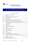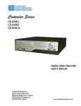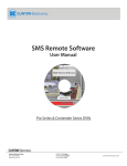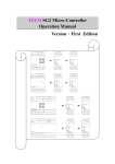
1
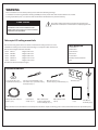
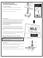
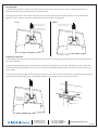
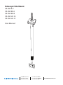
Telescopic Pole Mount
CE-CM-S-2
CE-CM-SX-6
CE-CM-SX-8
CE-CM-LX-12
CE-CM-LX-17
User Manual
M4 Washer
M4 x 45mm
M4 Washer
M4 Lock Nut
1/4”-20 x 2”
1/4”-20 Lock Nut
1/4” Lock Washer
1/4” Washer
1/4” Washer
M4 x 8mm
VESA screw
(4 places)
1/2”-13 Lock Nut
Fender Washer
Truss or Channel Strut
Min. Hole Size: 1/2”
Max. Hole Size: 5/8”
10
7/16
Min. Steel Thickness: 1/4”
Pole will move in
the direction of the
tightened bolt
CLINTON Electronics
6701 Clinton Road
Loves Park, IL 61111
1.800.447.3306 Sales
1.800.549.6393 Support
1.800.633.8712 Fax
www.clintonelectronics.com
WARNING
Prior to installation and use of this product, please observe the following warnings:
1. Installation and servicing should be done by qualified personnel, and all work done should conform to local codes.
2. Using replacement parts or accessories other than from the manufacturer may void the warranty.
This symbol indicates that there are important operating and
maintenance instructions in the literature accompanying this unit.
M4 Washer
CHANGES
OR MODIFICATIONS
NOT EXPRESSLY
Fender
Washer
APPROVED BY THE PARTY RESPONSIBLE FOR M4 Lock Nut
1/4”-20 x 2”
Truss or Channel
Strut
COMPLIANCE
COULD
VOID THE USERS AUTHORITY
Washer
1/4”-20M4
Lock
Nut
TO OPERATE THE EQUIPMENT.M4 x 45mm
SED W
1/4” Washer
Tools Required:
Heate
AC
r
7
AL
d
M
M
M
X
AU
1
1
3
7/16
5X20
FUSE
4
5
7
on
Pole Mount
Assembly (1 pc.)
r
ila
yI
np
s
ut
M4 Washer
M4 x 45mm
X
AU
x
Au
M4 x 8 VESA screws
(4 pcs.)
AL
6
M
2
M
M
AL
AL
AL
AC24V
8
AC220V
m
Pole will move in
the direction of the
tightened bolt
User Manual
(1 pc.)
+
Groun
m
Co
M4 x 10mm screw
to attach safety cable
to rear of display. (1 pc.)
2
ts
485B
485A
485B
AUX2
485A
Min. Steel Thickness: 1/4”
U-bolt cable
clamp. (1 pc.)
pu
COM
ALM5
ALM6
ALM7
COM
ALM1
ALM2
AUX1
Min. Hole Size: 1/2”
Max. Hole Size: 5/8”
Safety cable with crimped
eyelet. (1 pc.)
J1
ALM3
6 7 8
In
5
2
AC
6
AC220V
10 11 12 13 14 15 16 17 18 19
Min. Hole Size: 1/2”
Max. Hole Size: 5/8”
Min. Steel Thickness: 1/4”
485 In
put
m
4
ALM4
2 3
ar
Al
485B
485A
485B
485A
COM
ALM5
ALM6
ALM7
COM
ALM1
ALM2
1
Min. Steel Thickness: 1/4”
9
485B
-
5X20
JP2_2
5
FUSE
JP2
AC24V
JP
puts
AC24V FUSE
H&F
AC24V
Fender Washer
AUX2
+
1/2”-13 Lock Nut
4
Bracket (1 pc.)
14 15
485A
3
n Auxilary In
0204201792
Truss or Channel Strut
AUX1
485B
10 11 12 13 14 15 16 17 18 19
485A
9
AUX2
Outdoor Box
on
6 7 8
12 13
Model CE-PTZ-WP24
Comm
o
M4 x 8mm
VESA screw
(4 places)
m
5
485B
ut
tp
Ou
V ra
2
24 e
ra
1
AC Cam
om e
to
/C am
ux C
/A to
m era
m 1
Co m
a
/
ar ut
Al utp
ux C
/A to
O
COPM
9
m 2
J
ar ut
Al utp
ALM7
O
ALM6
4
ALM3
2 3
485A
COM
ALM4
ALM5
ALM6
ALM7
ALM1
1/4” Washer
AC24V
AUX1
AC220V
1
ALM4
Min. Hole Size: 1/2”
Max. Hole Size: 5/8”
AUX2
AUX1
1/4”-20 Lock Nut
J1
JP2_2
10 11 12 13 14 15 16 17 18 19
9
M4 Lock Nut
puts
AC220V
AC24V FUSE
JP2
M4 Washer
1/4”-20 x 2”
6 7 8
m
Co
H&F
AC24V
M4 x 45mm
Alarm
In
1/4” Lock Washer
1/4” Washer
M4 x 45 screw (1 pc.),
washers (2 pcs.), and locknut (1 pc.)
ALM5
1/4”-20 x 2” hex head bolt (1 pc.),
Trusswashers
or Channel
lock washer (1 pc.),
(2Strut
pcs.),
and locknut (1 pc.)
ALM4
M4 Washer
n
Fender Washer
1/2”-13 lock nut (1 pc.),
and fender washer (1 pc.)
ALM3
0204201792
ALM2
Comm
o
1/2”-13 Lock Nut
Outdoor Box
ALM1
COM
Model CE-PTZ-WP24
ALM2
COM
10
Truss or Channel Strut
1
5
4
M
85A
85B
85A
85B
LM7
LM6
LM5
LM4
LM3
LM2
LM1
OM
Fender Washer
RS485
C
Outpu ommu
t to Ca
me
AC220V
JP9
Included Hardware:
1/2”-13 Lock Nut
JP2_2
JP2
2 3
1
AC24V
Pole will move in
the direction of the
tightened bolt
AC220V
AC24V FUSE
J1
1 2
H&F
AC24V
19
17 18
15 16
13 14
11 12
9 10
7 8
6
5 x 20
m
3A 250 m fuse
V
&
2
7/16” wrench 4VIN Fan Output
A7mm
C24Vwrench
H&F
AC24V
10mm wrench
FUSE
FUSE
3/4” wrench
5X20
5/16”Jwrench
P2
JP2_2
#2 Phillips head screwdriver
level
2 3
4 5
6 7
8 9
10 11
ALM3
This bracket is designed to mount to mount
LCD from the ceiling structure. It can be
M4 xan
8mm
Min. Steel Thickness: 1/4”
VESA
screw
used with the existing truss structure of the building or in conjunction with channel strut.
(4 places)
There are four lengths of brackets available:
AC24V
O
1/4” Washer
to Cam utput
• Part # CM-S-2
Length of 22” to 35”
era
• Part # CM-SX-6
Length of 36” to 67”
Alarm
Outpu/Aux/Com
• Part # CM-SX-8
Length of 54” to 96”
t 1 to C
amera
Alarm
• Part # CM-LX-12
Length of 71” to 139”
Outpu/Aux/Com
t 2 to C
• Part # CM-LX-17
Length of 75” to 200”
amera
(Brackets are identical except for length)
1/4”-20 Lock Nut
M
CO
0204201792
5
0204201792
ut
Outd
M4 Lock Nut
3 4
Outdoor Box
AC24V
Aux. In
p
-WP24
CE-PTZ
Model
oor Box
Max. Hole Size: 5/8”
ITH ST
ANDA
Model CE-PTZ-WP24
AL
1/4” Lock Washer
Telescopic LCD ceiling mount
Info:
1/4” Washer
M4 Washer
NOT U
1/4”-20 Lock Nut
M
CO
M4 x 8mm
VESA screw
(4 places) Min. Hole Size: 1/2”
M4 Lock Nut
1/4” Washer
AL
1/4”-20 x 2”
M4 Washer
5X20
1/4” Lock Washer
1/4” Washer
FUSE
CAUTION
M4 Washer
1/2”-13 Lock Nut
M4 x 45mm
M4 Washer
7/16
10
Please check to ensure all hardware is included prior M4
toLock
installation.
If parts are missing, please contact Clinton Electronics for replacement parts.
Nut
48
1/4”-20 x 2”
nd
move in
the direction of the
M4tightened
x 8mm
bolt
ou
Gr
1/4”-20 Lock Nut
1/4” Lock
Washer
Pole
will
1/4” Washer
7/16
10
1/4” Washer
VESA screw
(4 places)
M4 x 45mm
Model CE-PTZ-WP24
Washer
Pole willM4
move
in
the direction of the
tightened bolt
M4 Washer
Outdoor Box
0204201792
1/4”-20M4
x 2”
Washer
M4 Lock Nut
d.
Assembly Instructions
U-Bolt Cable Clamp
1/2”-13 Lock Nut
If drilling is necessary,
Use 9/16” metal drill
bit to drill through steel
mounting surface.
Fender Washer
Truss mount or channel strut
mount
Cord Management Hole
Truss or Channel Strut
Securing Mount to Building:
1. Insert threaded rod between truss gap or into hole in channel strut.
Min. Hole Size: 1/2”
Max. Hole Size: 5/8”
2. Place 1/2” fender washer over the threaded rod and then 1/2” lock nut.
Min. Steel Thickness: 1/4”
3. Tighten the 1/2”-13 lock nut using a 3/4” wrench.
Hold lower pole section and
turn counter-clockwise to lo
7/16
10
Prevent display
9/16” from falling
holding lower pole section h
Pole will move in
the direction of the
tightened bolt
Mounting LCD to Pole:
1. If your LCD is supplied with a VESA plate already mounted on the back, simply
ensure the four M4 screws are in place and tightened. If the mount is not already
attached, connect it using the supplied M4 x 8mm VESA screws (4-places).
M4 x 45mm
Remove original
*NOTE: M4
Some
installations
may require running power and video cables
x 8mm
VESA
prior toscrew
attaching
thewith
LCD bracket to the pole. If this is the case, do so 1/4”-20 x 2”
& replace
M4
x
10mm
screw
before continuing to step 2.
M4 Washer
M4 Washer
M4 Lock Nut
1/4”-20 Lock Nut
1/4” Lock Washer
1/4” Washer
1/4” Washer
M4 Washer
M4 x 8mm
VESA screw
(4 places)
M4 x 45mm
1/4”-20 Lock Nut
1/4” Lock Washer
1/4” Washer
Truss or Channel Strut
1/2”-13 Lock Nut
Fender Washer
Truss or Channel Strut
Min. Steel Thickness: 1/4”
10
7/16
Min. Hole Size: 1/2”
Max. Hole Size: 5/8”
Pole will move in
the direction of the
tightened bolt
10
Pole will move in
the direction of the
tightened bolt
9/16”
Fender Washer
Min. Steel Thickness: 1/4”
Leveling the Pole
1. You can ensure the pole is plumb by tightening the 1/4”-20 lock nuts on the top
of the pole where it attaches to the structure using a 7/16” wrench.
3. Check and adjust 2 adjacent sides of the pole until it is plumb in each direction.
Max Load:
15kgs / 35lbs.
1/2”-13 Lock Nut
Min. Hole Size: 1/2”
Max. Hole Size: 5/8”
2. Place a level on the pole and tighten the nuts that correspond to the direction
that the pole needs to move (see illustration on the right).
1/4” Washer
M4 x 8mm
VESA screw
(4 places)
If drilling is necessary,
Use 9/16” metal drill
bit to drill through steel
mounting surface.
CAUTION: This stand is intended for use only with the maximum weights indicated.
Use with products heavier than the maximum weights indicated may result in
instability causing possible injury. This product is intended to mount to a steel
support truss, or channel strut.
M4 Lock Nut
1/4”-20 x 2”
3. Install the M4 x 45mm screw, washers, and lock nut into the upper slotted hole
according to the illustration on the right. You will use a #2 Phillips screwdriver
and a 7mm wrench to fully tighten in the next step.
4. Tighten the fasteners to secure the monitor at the desired angle.
*NOTE: Avoid overtightening which can cause the pole to indent.
M4 Washer
7/16
2. Hold the LCD with attached bracket up to the end of the pole mount, and
line up the wings of the bracket to the holes in the end of the pole. Insert the
1/4”-20 x 2” bolt, lock washer, washers, and lock nut in place according to the
illustration on the right. You will use 7/16” and 10mm wrenches to fully tighten
in step 4.
Adjusting Height:
1. Hold the lower pole (where it connects to the LCD) while loosening the center collar by turning it counter-clockwise (see illustration on
U-Bolt Cable Clamp
left below). Extend the pole by gently lowering it to the desired length.
rd Management Hole
2. Once the proper length has been maintained, lock the pole in position by rotating the center collar clockwise. The collar should be hand
tightened as snug as possible to prevent the pole from expanding. (see illustration on right below)
Loosen
Tighten
Secure assembly by turning collar clockwise:
hand tighten as snug as possible
Hold lower pole section and
turn counter-clockwise to loosen
Prevent display from falling by
holding lower pole section here
Secure assembly by turning collar clockwise:
hand tighten as snug as possible
U-Bolt Cable Clamp
Cord Management Hole
y with the maximum weights indicated.
m weights indicated may result in
uct is intended to mount to a steel
9/16”
If drilling is necessary,
Use 9/16” metal drill
bit to drill through steel
mounting surface.
Installing the Safety Cable:
Hold lower pole section and
1. Run the safety cable into the cable management hole in the top of the pole, and out through the bottom of the pole.
The crimped eyelet end
turn counter-clockwise to loosen
will connect to the LCD.
Prevent display from falling by
holding lower pole section here
2. Remove one of the M4 x 8mm VESA mount screws
from
U-Bolt Cable
Clampthe LCD-bracket assembly, then connect the crimped eyelet end of the safety cable
to the mount using the supplied M4 x 10mm screw. You can discard the unused M4 x 8mm VESA mount screw that has been removed as it is no
Cord Management Hole
longer needed.
Remove original
M4 x 8mm VESA
3. Connect the top end of the safety cable by
screwinserting
& replace with it through a hole in the truss or channel strut, and fasten using the U-Bolt cable clamp. Pull
M4 x 10mm screw
any remaining slack from the safety cable, and fully tighten the U-Bolt using a 5/16” wrench. Cut or loop any excess cable.
Secure assembly by turning collar cloc
hand tighten as snug as possible
Hold lower pole section and
turn counter-clockwise to loosen
Remove original
M4 x 8mm VESA
screw & replace with
M4 x 10mm screw
CAUTION: This stand is intended for use only with the maximum weights indicated.
Use with products heavier than the maximum weights indicated may result in
instability causing possible injury. This product is intended to mount to a steel
support truss, or channel strut.
9/16”
If drilling is necessary,
Use 9/16” metal drill
bit to drill through steel
mounting surface.
Prevent display from falling by
holding lower pole section here
U-Bolt Cable Clamp
1.800.447.3306 Sales
1.800.549.6393 Support
1.800.633.8712 Fax
Remove original
9/16”
CLINTON Electronics
6701 Clinton Road
CAUTION: This stand is intended for use only with the maximum weights indicated.
Loves Park, IL 61111
Use with products heavier than the maximum weights indicated may result in
instability causing possible injury. This product is intended to mount to a steel
support truss, or channel strut.
If drilling is necessary,
Use 9/16” metal drill
bit to drill through steel
mounting surface.
Cord Management Hole
www.clintonelectronics.com
v.04.06.11