1
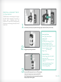
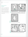
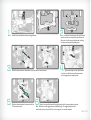
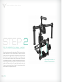
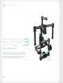
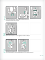
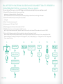
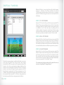
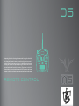
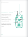
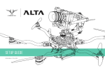
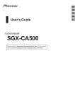
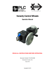
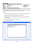
USER
A FREEFLY SYSTEMS INNOVATION
G U I D E
Freefly represents the intersection of art and technology. Our team consists of industry leading specialists all
focused on one task - inventing solutions to allow unrestricted camera movement. Freefly initially created the CineStar
line of multi-rotor camera platforms, which allowed smooth, stable and dynamic low-altitude aerial imagery. After
years of research and development in camera stability, Freefly has created the MōVI stabilized camera gimbal. Our
goal with the MōVI is to empower a new era of stabilized cinematography on a variety of platforms, from handheld to
helicopters and everything in between.
><
IN•ER•TIA
The Freefly MōVI is a digital 3 axis stabilization system that relies on
both active motor driven components and passive inertial stabilization.
Passive stabilization relies on the principles of inertia (tendency of an
object to resist change in its motion) and requires that the camera is
well-balanced in the Pan, Tilt, and Roll Axes. Active stabilization refers
to the techniques of using sensors to measure the camera’s Pan, Tilt,
and Roll movements and counteract those movements using motors
attached to the 3 axes. These 2 types of stabilization work in concert to
achieve the smooth and stable shots for which the MōVI is well known.
This manual will teach you how to setup, balance, and tune your MōVI
M5. For new users, the process of balancing and tuning a MōVI might
seem overwhelming at first, so allow some time to master the procedures
described in this manual.
2
MōVI
COMPONENTS:
1. Pan Motor
2. Pan Axis
3. Roll Motor
4. Roll Axis
5. Tilt Motor
6. Tilt Axis
7. Tilt Front to Back Adjustment
8. Roll Adjustment Point
9. Tilt Vertical Adjustment
1
3
5
6
9
7
8
4
CONTENTS
01 GETTING STARTED
Batteries and Battery Charger:
Charging the Battery
Installing the Battery
Mounting the Camera
02 BALANCING the MōVI
Step 1: Tilt Front to Back Balance
Step 2: Tilt Vertical Balance
Step 3: Roll Balance
Step 4: Pan Balance
03 CONVERTING M10 to MR
Attaching Landing Gear Legs & Octo Suspension Plate
Bluetooth Pairing/Freefly Configurator Connection
04 GUI / TUNING
Initial Tuning
Majestic Tuning
Pan Majestic Tuning
Tilt Majestic Tuning
GUI Parameter Definitions
05 REMOTE CONTROL
Remote Control Features
Mode Switch (Dual Operator, Majestic, Kill)
06 TROUBLESHOOTING
Symptoms, Possible Causes and Solutions
NOTICE
BOX CONTENTS
All instructions, warranties and other documents are subject to change
at the sole discretion of Freefly Systems Inc. (“Freefly”). For up-to-date
product literature, visit www.freeflysystems.com.
Qty 1 - MōVI M5 Handheld Stabilizer
Qty 1 - MōVI Top Handle
Qty 1 - Stand
Qty 2 - Freefly 14.8V 1.3Ah MōVI Batteries
Qty 1 - Freefly LiPo Charger with AC cord
and Charge Lead Adapter
Qty 1 - M2 Hex Driver
Qty 1 - M2.5 Hex Driver
DISCLAIMER
This is a sophisticated cinema product. It must be operated with caution
and common sense and requires some basic mechanical ability. Failure
to operate this product in a safe and responsible manner could result
in injury or damage to the product or other property. This User Guide
contains instructions for safety and operation. It is essential to read
the entire User Guide and follow all instructions and warnings in the
manual, prior to setup or use, in order to operate the MōVI correctly
and avoid damage or injury.
Freefly has made every effort to provide clear and accurate
information in this User Guide, which is provided solely for the user’s
knowledge. While thought to be accurate, the information in this
document is provided strictly “as is” and Freefly will not be held
responsible for issues arising from typographical errors or user’s
interpretation of the language used in this User Guide that is different
from that intended by Freefly.
Freefly reserves the right to revise this User Guide and make changes
from time to time without obligation to notify any person of such
revisions or changes. In no event shall Freefly, its employees or
authorized agents be liable for any damages or losses, direct or
indirect, arising from the use of any technical or operational
information contained in this document.
OPTIONAL ACCESSORIES
Qty 1 - DX7 Transmitter*
*Included with DX7 Transmitter:
Qty 1 - 2000MAh NiMh Transmitter Battery Pack
Qty 1 - SD Card
Qty 1 - 12V DC Power Supply
Qty 1 - DX7s Neck Strap
Qty 1 - DX7s User Manual
01
GETTING STARTED
GETTING STARTED
BATTERIES AND BATTERY CHARGER
WARNING: You must read these safety instructions and warnings
carefully before charging or using your batteries. Failure to exercise
caution while using Lithium Polymer (LiPo) batteries and comply
with the following warnings could result in battery malfunction,
electrical issues, excessive heat, fire, or injury and property damage.
• Never charge or store batteries in extremely hot or cold places
(recommended between 50º-80ºF/10º-26ºC), leave in a hot
environment (inside an automobile in hot weather), or leave in direct
sunlight.
• Never place or carry batteries in your pockets or clothing.
• Always use Freefly-approved LiPo batteries.
• Always inspect the battery before charging.
GENERAL GUIDELINES AND WARNINGS
You must read these safety instructions and warnings carefully
before charging or using your battery.
• Stop using or charging the battery immediately if the battery
becomes or appears damaged, starts to balloon or swell, leaks,
becomes deformed or gives off an odor, exceeds a temperature of
160ºF (71ºC), or if anything else abnormal occurs. Disconnect the
battery and observe in a safe area outside of any building or vehicle
for at least 45 minutes, as a damaged battery can experience a
delayed chemical reaction that could possibly result in fire.
• Never disassemble, modify, puncture, shock, drop, crash and/or
short circuit the battery. Leakage, smoke emission, ignition,
explosion or fire can occur, which may result in personal injury or
property damage.
• DO NOT leave the battery and charger unattended during use.
• Never drop charger or batteries.
• Never attempt to charge “dead” or damaged batteries.
• Never charge a battery if the cable has been pinched or shortened.
• Never allow minors to charge or use battery packs without
adult supervision.
• Never allow batteries to come in contact with moisture at any time.
01—P1
• Always connect the positive red lead (+) and negative black lead (-)
terminals of the battery to the charger terminals correctly.
• Always disconnect the battery after charging, and let the charger
cool between charges.
• If a battery will not be used for more than one week, it is recommended
that the battery is stored with a voltage of approximately 3.8V per
cell. Do not store the battery fully charged. Store the battery at room
temperature in a cool or shaded area (ideally between 50º-80ºF
/10º-26ºC).
• Batteries should be stored in a vented, fire-resistant container. No
more than two batteries should be placed in a container to avoid
chain reactions. Storage temperatures should not fall below
32ºF/0ºC or above 130ºF/54ºC. Damaged batteries are extremely
sensitive to temperature fluctuation and care should be taken in
their immediate disposal. High temperatures may cause fire, even
with undamaged batteries.
NOTICE: All instructions and warnings must be followed exactly.
Mishandling of LiPo batteries can result in fire. By handling, charging
or using the included LiPo batteries, you assume all risks associated
with LiPo batteries. If you are not prepared to accept complete
liability for the purchase and/or use of the batteries, you are advised
to return them in new and unused condition to the place of purchase
immediately.
IMPORTANT NOTE: If you are using the battery to power or charge an
accessory used with the MōVI, it is your responsibility to constantly
monitor the battery’s voltage through the use of a voltage checker. If
the accessory drains the battery below 3.0V per cell, it will damage the
battery and render the battery unusable. Never attempt to charge a
battery that has individual cell voltages below 3.0V.
CHARGING PROCESS WARNINGS AND SAFETY PRECAUTIONS
BATTERY DISPOSAL:
• Never charge or use a LiPo battery that shows any damage or
disfigurement of any kind, as this may be a sign of internal damage.
Any damage to the protective cover, wiring or plugs is also reason to
discontinue use.
NOTICE: LiPo batteries require special handling for safe disposal. The
following steps must be taken to avoid damage or injury to yourself,
your property or anyone who comes in contact with the battery.
• Never leave the lead wires dangling from a battery.
• Never charge a battery unattended.
• Never connect more than one battery pack to the charger at a time.
If the battery is undamaged but no longer useful:
1.Discharge the battery to a maximum of 1.0V per cell using a safe
discharge method.
• Never charge near moisture, extreme temperatures, flammable or
combustible materials.
2.Leave the battery uncharged and retest the battery after 24 hours. If
the battery is over 1.0V per cell, repeat the procedure until the
battery is 1.0V per cell or less.
• Never charge the battery while installed on the MōVI or other
equipment or while inside a vehicle.
3.Place electrical tape over each wire lead and tape the wire leads to
opposite sides of the battery.
• Never attempt to charge a battery that is damaged or has individual
cell voltages below 3.0V.
4.Place battery in a sealed plastic bag and place plastic bag in a vented,
fire-safe container.
• Always inspect batteries before charging.
5.Use a fire-safe container to deliver battery to a recycling center
authorized for LiPo batteries. Please note that not all batteryrecycling services include LiPo batteries. If no LiPo recycling facility
is available in your area, contact your state or local HAZMAT agency
for instructions.
• Always use a specific LiPo charger only. Do not use a Nickel-cadmium
(NiCd) or Nickel-metal hydride (NiMh) charger, even though these
chargers may appear similar to a LiPo charger. Failure to do so may
cause a fire, which may result in personal injury and/or property
damage.
• Always let the battery cool down to ambient temperature before
charging.
• Always monitor the temperature of the battery while charging. If the
battery becomes hot to the touch or begins to swell, discontinue
charging immediately. Disconnect the battery from the charger and
observe it is a safe place for at least 45 minutes.
• Always ensure that the proper cell count or voltage is selected on
your charger for this battery. Failure to properly set the cell count or
voltage could result in fire or explosion of the battery.
If the battery is damaged:
1.If the battery or wiring is damaged, please contact your state or local
HAZMAT facility for instructions. Batteries must be rendered safe
before being transported or recycled.
2.DO NOT transport or ship batteries which have more than 1.0V per
cell charged OR that show signs of damage without following the
instructions given by the HAZMAT agency.
• For optimal performance and extended life, do not allow your battery
voltage to drop below 3.4V. It is recommended that you use a voltage
checker to actively monitor battery voltage.
01—P2
GETTING STARTED
CHARGING the BATTERY
1. Insert the AC power cord into the charger.
1.
2.
3.
4.
5.
2. Insert the AC power cord into the wall socket. All LEDs will light for 1
second and the charge status LED will flash green, which indicates
the charger is ready to charge.
3. Select “LiPo” on the battery type switch.
4. Select the “1A” charging current on the charge current switch when
charging the included batteries.
5. Connect battery main charge lead to the charge lead input in the
front of the charger. Make sure the red plug is plugged into the red
charge socket and the black plug is plugged into the black charge
socket.
6. Connect the Freefly 4s 1.3Ah battery to the charge lead. Always
connect the positive red lead (+) and negative black lead (-)
terminals to the corresponding colored terminals on the charger.
‘LiPo’
‘1A’
7. Connect the battery balance lead to the “4S” balance socket on the
side of the charger. The charger will automatically start charging.
10. Unplug the battery from the balance port and charge lead. The battery
is ready for use in your MōVI M5.
7-9.
- +
01—P3
‘4S’
BATT.
9. When the battery is fully charged, the “charge status” LED will glow
constant green.
6.
BATT.
8. The charge status LED and the cell status LED will light constant red.
The cell 1-4 LED’s will glow continuously indicating a 4 cell battery
pack.
-
+
INSTALLING BATTERY
in the MōVI
The MōVI battery is custom designed to fit snugly in
the MōVI battery compartment. The battery is
retained using a lightweight plastic latch
mechanism. Be careful when installing/removing
the battery to avoid damaging the battery lead and
balance lead.
1.
Insert battery into battery compartment observing proper orientation (Freefly sticker visible).
Battery Specification
2.
Engage battery latching mechanism.
Battery Type: Lithium Polymer
Capacity: 1.3Ah
Voltage: 14.8v
Max Continuous Discharge: 3C (3.9A)
Max Burst Discharge: 5C (6.5A)
Max Charge Voltage: 4.2V per cell
Minimum Discharge Voltage: 3.0V per cell
Dimensions: [69mm (L) x 34mm
(W) x 28mm (H)]
Weight: 125g
Charger Specification
AC Input Voltage: 100-240V, 50-60HZ
Output Power: 20W
Charging Current (Selected by Switch):
1A, 2A, 3A
Current Drain for Balancing: 200mA
4 LEDs for Balancing Indicator
1 LED for Charging Status
3.
Ensure the MōVI power switch is set to “off” and plug the
battery into the power input connector on the MōVI.
Note: The battery and input connector are keyed. Do not force the
battery and input connector together.
01—P4
GETTING STARTED
MOUNTING the
CAMERA
The MōVI uses a custom lightweight adjustable
camera rail to allow you to easily balance, install,
and remove your camera package. It is important
that you fully build your camera package prior to
installing it on the M5. Adding accessories after
balancing the M5 would necessitate re-balancing,
so it is best to install all accessories (follow focus
motors, receivers, batteries, etc.) prior to mounting
the camera to the MōVI.
1.
2.
3.
01—P5
Attach the bottom camera rail to your camera using the provided ¼ - 20 screw. Please note that there
are multiple attachment holes in the camera rail to choose from to cater to different camera layouts.
Install the hot shoe adapter into the hot shoe of your camera.
Attach the top camera rail to the hot shoe adapter using the provided M3x6 flat head screws.
02
One of the most critical factors in achieving optimal performance from
the MōVI is proper balancing. The better the camera is balanced, the
less work the motors have to do to achieve a stable shot. Accurate
balance is highly critical in shots where the MōVI will be subjected to
extreme movements or accelerations (running, horseback, biking, car
mount, helicopter, etc.).
There are 3 Axes we need to accurately balance prior to turning the
MōVI on and setting up the software. To reiterate, the camera needs to
be fully setup with all accessories prior to installing and balancing the
camera on the gimbal. The addition of accessories (follow focus motors,
receivers, etc.) will cause the balance to shift, so they need to be
installed prior to beginning the balancing process.
1
2
BALANCING the MōVI
3
BALANCING the MōVI
STEP 1
TILT FRONT-TO-BACK BALANCE:
The goal with Step 1 is to balance the camera front-to-back on the Tilt
Axis. When the proper front/back tilt balance is achieved, the camera
will stay level if you remove your hands. Please note that to confirm
proper tilt front/back balance, the camera and Tilt Axis need to be
level. At this stage, we have not balanced the camera vertically for the
Tilt Axis, so it is only possible to confirm tilt front/back balance when
the camera and tilt axis are level. If the camera is sitting too low or too
high with respect to the Tilt Axis, it will mask the issue of front to back
balance. To adjust the balance, loosen the single middle toggle clamp
under the camera and the single middle toggle clamp on top of the
camera. This will allow the camera and mount plates to slide forwards
and backwards. Be careful to ensure that the clamps are fully engaged
and the camera is securely mounted to the adjustable camera plates as
you complete step 1.
02—P7
slide adjustable camera
plates to balance tilt axis
1.
3.
5.
Loosen the top and bottom camera rail toggle clamps.
Slide the camera and mount plates onto the top and bottom camera mounts.
Slide the camera forward or backwards until the
Tilt Axis remains level.
2.
Loosen the side clamps on the top horizontal
cross bar so that it can move freely up and down to
allow you to set the correct height when installing
the camera and adjustable camera plates.
4.
Tighten side clamps on the top horizontal
cross bar once both the top and bottom camera
rail are engaged on the camera plates.
6.
Tighten the top and bottom middle toggle clamp to lock the camera plate in position.
Note - Please be sure the toggle clamp is adequately tight. The toggle clamp holds the
camera and camera rail onto the MōVI, so it is important it is securely clamped.
02—P8
BALANCING the MōVI
STEP 2
TILT VERTICAL BALANCE:
Now that we have successfully balanced the Tilt Axis front-to-back, we
need to adjust the Tilt Axis vertical balance. To adjust the vertical
balance, there are 4 toggle clamps on the middle of the four small side
tubes. Adjust the camera position vertically until it is balanced such
that you can rotate the camera to any tilt angle and it will naturally
stay wherever you leave it. If you point the lens down and it wants to
continue tilting forward on its own, then it is top heavy and the camera
needs to shift down vertically. If you point the camera lens down and
it wants to return to level, then you know it is bottom heavy and the
camera needs to shift upwards vertically.
02—P9
adjust height of crossbar to
achieve tilt vertical balance
1.
Identify which way the camera needs to be adjusted by tipping the camera lens down 20 degrees.
If the camera returns to horizontal, then the Tilt Axis is bottom heavy. If the camera
continues to rotate down when released, then Tilt Vertical Axis is top heavy.
2.
Rotate the Tilt Axis so that the camera lens
is pointing straight up.
5.
Tighten the toggles.
3.
Loosen the 4 vertical adjustment toggles.
6.
4.
Confirm good balance by moving the camera to
several tilt angles and confirming that it holds the
given angle without user input.
Slide the camera cage and camera forward or
backward until the camera remains pointing
straight up when released.
02—P10
BALANCING the MōVI
STEP 3
ROLL BALANCE:
With the Tilt Axis completely balanced, we can move onto balancing
the Roll Axis. To adjust rol balance we need to loosen the 2 bottom
outer toggle clamps and the top toggle clamp. This will allow the
camera and cage to slide side-to-side to achieve roll balance.
02—P11
roll balance
adjustment point
1.
2.
3.
Loosen the 2 lower outer toggle clamps and 1 upper outer toggle clamp on the camera platform and slide
camera and platform side-to-side to achieve proper balance.
Tighten the 2 lower outer toggle clamps and 1 upper outer toggle clamp and upper clamp to lock roll in place.
Confirm roll balance by moving Roll Axis to several locations and ensuring the axis will hold the given angle without user input.
02—P12
BALANCING the MōVI
1- tip the gimbal to
check pan axis balance
2- slide pan knuckle to
adjust pan balance
STEP 4
PAN BALANCE:
Pan is perhaps the most difficult axis to visualize balancing. The end
goal is that the entire mass below the pan motor would be balanced on
the central axis line of the pan motor. The easiest way to check for Pan
Axis balance is to slightly tilt the MōVI in the stand and see which way
the Pan Axis swings. The clamp that holds the vertical tube to the top
horizontal tube is the only adjustment for Pan Axis balance. By sliding
this joint fore/aft we can achieve proper Pan balance.
02—P13
FORE/AFT PAN BALANCE:
1. Mount the MōVI in the stand with the power off.
2. Loosen the 2 handle toggle clamps and rotate
the handlebar upwards.
3. Align the MōVI such that the camera lens is
lined up with the long top handle bar.
4. Using the handles, rotate the MōVI 5-10
degrees and observe which way pan rotates
5. If the lens points to the low side, it indicates
that the MōVI is nose heavy and the Pan knuckle
needs to slide backwards.
6. If the back of the gimbal points to the low side, it
indicates that the MōVI is tail heavy and the Pan
knuckle needs to slide forwards.
M3 SCREWS
7. Loosen the 2 toggle clamps on the Pan knuckle
to allow the knuckle to slide.
8. Slide the gimbal in the direction needed as
indicated in Steps 5 and 6. Tigthen the 2 Pan
toggle clamps.
9. Confirm that the camera will not swing to the left
or right when you rotate the MōVI handles 5-10
degrees. This indicates proper fore/aft balance.
02—P14
M3 SCREWS
02—P15
03
CONVERTING M5 to MR
CONVERTING M10 to MR
M5 to
MR
CONVERSION:
The MōVI M5 is designed to quickly transform to the Multi-Rotor (MR)
version. The following steps will allow you to convert your M5 to MR
and mount the gimbal to a CineStar multi-rotor.
03—P17
1.
Replace the aluminum stepped tube with the 180mm carbon tube. You will need to loosen the 4 screws holding the aluminum tube to the Pan motor housing
and slide it out. In its place, install the carbon tube with the rear landing gear attached.
M3x8 SCREWS
2.
Attach the left and right landing gear legs and tubes to the M5 using the provided M3x8 Socket Head Cap Screws.
M3x8 SCREWS
3.
Attach the Octo Suspension Plate using the provided M3x8 Socket Head Cap Screws.
03—P18
BLUETOOTH PAIRING GUIDE AND CONNECTION TO FREEFLY
CONFIGURATOR for Android, PC and MAC:
For connectivity to an iOS device, please refer to the Wi-Fi Adapter Installation Manual found at http://freeflysystems.com/software-manuals/.
1. Power the MōVI stabilizer and wait for it to boot correctly. Under
control panel •••> Hardware and Sound •••> Bluetooth Devices
Click on “Add Wireless Device”. This window may also be accessed by clicking on Bluetooth Icon at bottom right of the screen.
2. Select the MōVI stabilizer device (the name may have been customized
or changed).
3. Click on “Enter the device’s pairing code”.
4. Enter the password “1234” and click “Next”.
5. Bluetooth pairing process should start, and then complete –click “Close”.
6. The MōVI should now be successfully paired and available for use by
the GUI. Right-click on the icon and select “Properties”, then click on “Services” to find out the COM Port number – in this case it is COM67.
7. Start the Freefly Configurator application (first close application and re-run if already open), it should
discover the new COM port we have just added. Select the correct COM port from the list and then click “Connect”. After a short while the GUI will
connect and display an info message. You may now click “Configuration”, “Chart”, “Heads up display”, etc....”Configuration” and “Chart” are generally
2 items required for tuning.
1.
2.
‘Control Panel’
‘Hardware & Sound’
3.
4.
‘Enter the device’s
pairing code’
‘1234’
5.
6.
‘Properties’
‘Next’
‘Close’
‘On’
03—P19
‘Bluetooth Devices’
‘Services’
‘Add Wireless Device’
‘COM67’
04
The Freefly Configuration GUI (Graphical User Interface) is the tool
that allows you to adjust the software parameters of the MōVI.
Changing these parameters will allow you to custom-tailor the MōVI’s
behavior for particular shots, as well as complete the initial setup
required for the MōVI. An important point to note is that you can
change parameters in the GUI live with a tablet, but the changes will
not be saved unless you write the configuration changes. This tells the
MōVI to store the new settings and recall them upon power-up.
GUI / TUNING
INITIAL TUNING:
When the ‘Stiffness’ is set too high, there will be high frequency
‘buzzing,’ or oscillations. Once these oscillations are felt, the
‘Stiffness’ setting should be reduced until they stop. It is helpful to
reduce the ‘Stiffness’ setting for each axis to a low value like 10 for
initial setup.
STEP 1. TILT STIFFNESS
Under the “Tilt” tab of the GUI, you will find a menu item called “Tilt
Stiffness”. This parameter will determine how ‘stiff’ the Tilt Axis will be
in holding the camera still. Slowly increase this setting until you feel
an oscillation in the Tilt Axis, then reduce the setting until the
oscillation subsides. It is important to check that the ‘Stiffness’ setting
you have set will not oscillate in any orientation. To confirm this, point
the camera up and down and make sure that the Tilt Axis is stable.
STEP 2. ROLL STIFFNESS
Under the “Roll” tab of the GUI, you will find a menu item called “Roll
Stiffness”. Slowly increase this setting until you feel an oscillation in
the Roll Axis, then reduce the setting until the oscillation subsides.
Pick the MōVI up and make sure that you can move the handles around
in a normal fashion and that no oscillations are present as you move.
STEP 3. PAN STIFFNESS
Above: Freefly MōVI Configuration Graphical User Interface
Now that the camera package is installed and balanced, we can move
onto tuning the gimbal. Each time the camera setup changes
substantially, the MōVI may need some GUI parameters adjusted. The
reason for this is that as you change the weight and balance of the
camera and lens substantially, the maximum ‘Stiffness’ setting that
each axis can achieve will change. The primary parameter in the GUI
that will need to be adjusted is the ‘Stiffness’ value for each axis. The
‘Stiffness’ setting adjusts the degree to which the MōVI tries to correct
for unwanted camera movement. The ‘Stiffness’ setting needs to be
set as high as possible without creating unwanted oscillations.
04—P21
Under the “Pan” tab of the GUI, you will find a menu item called “Pan
Stiffness”. Slowly increase this setting until you feel an oscillation in
the Pan Axis, then reduce the setting until the oscillation subsides.
Pick up the MōVI and hold it by the center single handle and ensure
that no oscillations are present. Holding by the single middle handle is
the worst case scenario for “Pan Stiffness” setting.
This concludes the initial gain settings of the gimbal. Now we can
move on to setting Majestic Tuning parameters.
MAJESTIC TUNING:
Now that we have the 3 main ‘Stiffness’ settings dialed-in, we can
discuss the various ways that we can tune Majestic Mode. Majestic
Mode refers to the single operator mode on the MōVI, where the MōVI
operator can control the pan and tilt of the MōVI without the need for
a 2nd operator. The MōVI has a difficult task in Majestic Mode;
essentially, we are asking the system to provide stable footage, but
follow the user’s input from the handles. These 2 things are somewhat
contradictory. The Majestic Mode tuning parameters in the GUI allow
the user to configure the Majestic Mode to suit the particular shot,
from very slow and smooth, to very fast and active.
PAN MAJESTIC TUNING:
Pan Majestic Smoothing- This parameter adjusts how much smoothing
is applied to the Pan Axis in Majestic Mode. A lower value means the
camera will follow the handles more actively, but will make it more
difficult to achieve very smooth pans. A higher value will cause the
camera to lag behind the handles more, but will allow for very smooth
and precise framing when panning. This can be useful when using
longer lenses or when subtle moves are needed. A setting of around 5
usually provides a good starting point.
Pan Majestic Window - Pan Majestic Window defines a range in degrees
of handle movement which will be ignored. In practice, this means that
you can move the handles less than the Pan Majestic Window and the
camera will not pan. Once you exceed the Pan Majestic Window
threshold, the camera will begin to pan. A normal default setting of 10
is a good place to start. In some circumstances where you will be
moving the handles drastically, you can increase the Pan Majestic
Window to a much higher value. An example would be when riding a
horse or motorcycle with the MōVI. The operator might be unable to
keep the handles still, but does not want the camera to pan each time
that he/she moves. Setting the Pan Majestic Window to 30 or 40
degrees would mean the operator could move the handles quite
drastically without disturbing the shot. The operator could still
re-frame the shot by exceeding the threshold.
feel too abrupt. A higher setting like 180 degrees is useful for very
subtle framing or long lens shots.
TILT MAJESTIC TUNING:
There are a few different Tilt Axis control modes which can be useful
for different situations.
Smooth-Lock - In this mode, the tilt angle can be manipulated by the
operator. The MōVI operator can manually point the camera at any tilt
angle and the MōVI will maintain that tilt angle setting. This can be
very useful for scenes where the tilt angle needs to remain constant
even as the operator moves around.
Note - If the remote control is turned on and set to “Majestic Mode”, it
is possible for the remote operator to control tilt while the MōVI
operator controls pan.
Majestic Angle - This mode works much the same as the standard Pan
Majestic Mode works. It allows the operator to tilt the handles of the
MōVI to adjust the camera tilt angle. One important point is that this
can be difficult to do with large camera payloads. For these situations,
if the operator becomes fatigued, we recommend using the “normal”
setting, or a remote operator to control tilt.
Pan Majestic Span - Pan Majestic Span alters the amount of rotation
from the handles to achieve maximum panning speed. A good default
setting is 135 degrees. Too low a setting will make the Majestic Pan
04—P22
GUI PARAMETER DEFINITIONS:
Tuning Menu: This menu contains settings that control the stiffness of each axis, or how much the
motors are used for active stabilization. The ideal amount depends on the camera weight and rigidity.
For guidelines, refer to the Knowledge Base at www.freeflysystems.com.
Pan Stiffness/Roll Stiffness/Tilt Stiffness - Controls how ‘stiffly’ the corresponding Axis will try
to hold the camera stable. The higher you can run the setting without vibrati on or oscillation, the
better.
Majestic Config Menu: This menu controls the behavior of the gimbal when in Majestic Mode.
Pan Smoothing - This parameter adjusts how much smoothing is applied to the Pan Axis in Majestic
Mode. A lower value means the camera will follow the handles more actively, but will make it more
difficult to achieve very smooth pans. A higher value will cause the camera to lag behind the
handles more, but will allow for very smooth motion when panning.
Pan Window - This defines a range (in degrees) of handle pan movement that will be ignored. See
further explanation in ‘Majestic Tuning’ section.
Tilt Mode - Allows you to choose between Smooth Lock and Majestic Angle control. See detailed
description in the ‘Majestic Tuning’ section.
Tilt Smoothing - This parameter adjusts how much smoothing is applied to the Tilt Axis in Majestic
Mode. A lower value means the camera will follow the handles more actively, but will make it more
difficult to achieve very smooth tilts. A higher value will cause the camera to lag behind the
handles more, but will allow for very smooth motion when tilting.
Tilt Window - This defines a range (in degrees) of handle tilt movement that will be ignored. See
further explanation in ‘Majestic Tuning’ section.
General Menu: This menu contains general settings for gimbal behavior.
Gimbal Application - Configures the gimbal for either Handheld or Airborne use. In Handheld use,
the center position of the Dual Operator Mode Switch enables Pan Majestic operation. In Airborne
use, the center position of the Dual Operator Mode Switch parks the gimbal for takeoff and
landing.
Roll Trim - Allows you to input a roll trim to level the camera via the GUI. This roll trim is applied
whenever the gimbal is in Majestic Mode. In Dual Operator mode, roll trim is controlled by the Dual
Operator Radio Controller. Be sure to write the configuration to the MōVI if you want the roll trim
to remain after re-powering the system.
Pan Trim - Allows user to adjust the neutral setting for the Pan Axis. This can be helpful for single
operator MR gimbals where you want the camera lens to align with the front of the aircraft
Max Tilt Angle - Sets the maximum angle of the Tilt Axis when looking up. Use to set soft-stops to
prevent the camera or lens from hitting the gimbal, or to prevent wires from being pulled out.
Min Tilt Angle - Sets the minimum angle of the Tilt Axis when looking down. Use to set soft-stops
to prevent the camera or lens from hitting the gimbal, or to prevent wires from being pulled out.
04—P23
Remote Operator Config Menu: This menu contains preferences for operation in Dual Operator mode.
Use these settings to adjust the feel of the Pan and Tilt joysticks.
Pan Joystick Smoothing - Sets how much smoothing is applied to the Pan Joystick in Dual Operator
mode.
Pan Joystick Expo - Sets how much exponential is applied to the Pan Joystick in Dual Operator mode.
Higher exponential makes the joystick less sensitive in the center and more sensitive at the edges.
Pan Joystick Window - This defines a range of Pan Joystick movement that will be ignored at the
center of the joystick travel.
Tilt Joystick Smoothing - Sets how much smoothing is applied to the Tilt Joystick in Dual Operator
mode.
Tilt Joystick Expo - Sets how much exponential is applied to the Tilt Joystick in Dual Operator mode.
Higher exponential makes the joystick less sensitive in the center and more sensitive at the edges.
Tilt Joystick Window - This defines a range of Tilt Joystick movement that will be ignored at the center
of the joystick travel.
Pan/Tilt Remote Speed Adjustment - Defines whether the Pan and Tilt Rates are controlled together
(Combined) or separately (Independent). In Combined mode, the Pan Rate control applies to both Pan
and Tilt.
Remote Rate Scale - Default value is 100 deg/sec. Adjustable from 1-200 deg/sec. This value will
allow you to increase or decrease the maximum rate available for Pan and Tilt when the remote is in
use.
Tilt Control Mode - Tilt can be set to either Rate or Angle mode. Rate is default. Angle mode is
recommended for single operator multi-rotor operations where control over Tilt is desired on a dial
type knob.
Remote Controller Config Menu: This menu defines how the joysticks and buttons of the Dual Operator
Remote Controller are mapped to gimbal movement. Warning– Misconfiguring the remote controller
mapping can result in undesired gimbal movement!
Mapping for Spektrum Transmitter
Radio Type
Map Remote Mode
Map Remote Pan
Map Remote Pan Rate
Map Remote Tilt
Map Remote Tilt Rate
Map Remote Roll Trim
S. DSMX 2048
6
-2
1
-3
-7
-4
Mapping for Futaba Transmitter
Radio Type
Map Pan Rate Clamp
Map RC Mode
Map RC Pan
Map RC Roll Trim
Map RC Tilt
Map RC Tilt rate Clamp
If you are using the Freefly MōVI Controller, please refer to it’s User Manual.
S. Bus
-7
-5
1
4
2
6
Radio Type – Select the type of radio receiver you are using.
Map Remote Mode – Radio channel corresponding to the three-position Mode Switch.
Map Remote Pan – Radio channel corresponding to the Pan joystick.
Map Remote Pan Rate – Radio channel corresponding to the Pan Speed joystick or knob.
Map Remote Tilt – Radio channel corresponding to the Tilt joystick. To reverse the behavior of the Tilt
joystick, use a negative number.
Map Remote Tilt Rate – Radio channel corresponding to the Tilt Speed joystick or knob.
Map Remote Roll Trim – Radio channel corresponding to the Roll Trim switch.
Map Remote Shutter – Radio channel corresponding to the Remote Shutter switch.
Shutter Type – Options are Pulsed, Latched or Camera I/F. Set this for the shutter type of the camera to
be used.
Expert Menu: This menu contains expert settings that normally do not need to be adjusted. Leave these
settings at the factory default unless they are required for troubleshooting.
Pan/Tilt/Roll Hold Strength Settings – These values control how strongly each axis follows and holds
the commanded position. A higher Hold Strength allows faster panning and tilting in Dual Operator and
Majestic Mode, but may cause overshoot with heavier cameras. A lower Hold Strength provides
additional smoothing. (See Pan/Tilt Joystick Smoothing and Majestic Pan/Tilt Smoothing for other
ways to adjust smoothing on each axis.) The default value (8) works well for a large range of cameras.
Gyro Filter – This setting adjusts the strength of the filter applied to the Gimbal’s gyro sensors. If the
Gimbal is experiencing oscillations that cannot be corrected by adjusting Stiffness settings, you can
use the Gyro Filter to further tune the Gimbal and remove oscillations. As a general rule, if the
oscillations are fast and rough in nature (buzzing), try increasing the Gyro Filter. If the oscillations are
slow and smooth in nature (rocking), try decreasing the Gyro Filter.
Output Filter – This setting adjusts the strength of the filter applied to the Gimbal’s motor outputs. If
the Gimbal is experiencing oscillations that cannot be corrected by adjusting stiffness settings, you
can use the Output Filter to further tune the Gimbal and remove oscillations. As a general rule, if the
oscillations are fast and rough in nature (buzzing), try increasing the Output Filter. If the oscillations
are slow and smooth in nature (rocking), try decreasing the Output Filter.
Shaky-cam Pan / Tilt – A feature has been exposed to allow operators enhance their filming. Shaky Cam
senses movement of the gimbal (acceleration in both the vertical and horizontal axis’), and can add
some of that signal into the tilt and pan motors as a form of deliberate pointing corruption. The scaling
factors are adjustable where zero disables the corruption, and larger positive or negative values give a
progressively stronger lead or lag effect. Lead is where the camera accelerates to tilt more upward
when the gimbal is accelerated up, lag is the opposite with the camera briefly pointing more
downwards for an up move. Similarly applied for lateral movements affecting the Pan Axis. Both
effects may be enabled and tuned independently. The effects maybe be observed for test purposes by
using larger scaling factors and moving the gimbal around more sharply. It is possible to dial in a relatively
consistent behavior suitable for a particular action shot - typically this would be with the camera operator
running whilst shooting a scene. The stabilization is otherwise unaffected except for this cyclic operator
induced noise.
Setdown Sleep -When set to ON, Setdown Sleep will enable the MōVI to be set down while powered
without the use of a stand. This can be useful in situations where the stand is not readily available in a fast
moving shooting environment. After sensing the motors are stalled for more than 4 seconds, the MōVI will
enter Setdown Sleep mode. While in this mode, the three LEDs on the MōVI will be flashing indicating the
sleep state. To exit, simply pick up the MōVI. Although the motors are drawing very little power while in
this mode.
Motion Booting – Motion booting bypasses the gyro self test procedure and allows the gimbal to boot up
even on a moving platform. It is recommended for situations such as filming from boats. For normal use it
is recommended to leave this feature disabled to allow for improved gyro calibration.
Aux Port Function -Selects the function of the Aux Port on the MōVI GCU. Available selections are UART
and Shutter where UART is default. Select UART when using the Freefly MōVI Controller to enable
communication between the MōVI and the receiver. Select Shutter to enable shutter release or
start/stop functionality via other 3rd party controllers. Output signal of the Aux Port when set to shutter:
Pin 1 Aux port = GND, Pin 3 Aux port = Shutter input. Map Remote Shutter and Shutter Type settings must
also be set.
Heading Assist -Selections available are OFF, Fixed Mount, GPS, and Compass. OFF is default and is no
change from how the MōVI performed previous to this update. Fixed Mount is available for use on in
stationary type setup such as on a tripod. Using this setting, the MōVI references only motor position
during pan moves, thus eliminating drift. When set to GPS this will allow for increased performance during
higher accelerations common when used with a multi-rotor platform. Set to Compass for increased
handheld performance. A Declination value should be set when in Compass.
Declination -Set local declination value for shooting location. This information is used when Heading
Assist is set to Compass. Local magnetic declination values can be found online.
Logging Rate -Available options are 5Hz, 10Hz, and 25Hz logging rates. To be used when Data Logging is
set to ON.
Data Logging -Enables logging data from the MōVI via Micro SD card slot on the MōVI GCU. Frequency of
data stream can be set via Logging Rate. When Data Logging is set to ON, the LEDs on the MōVI will flash at
a frequency corresponding to the Logging Rate setting. Some data may be unavailable without GPS signal
or when Heading Assist is set to OFF. To avoid potential corruption of data, Data Logging should be set to
OFF before de-powering the MōVI. Data Logging exports a wide range of parameters and is currently
available for use in a raw format.
Autotune – MōVI Controller Support 3.08 introduces the ability to automatically calibrate stiffness
settings on a balanced MōVI. To initiate the Autotune function, go to SYSTEM-> Autotune. With the MōVI in
the stand and stable, Autotune will go through the steps required to tune the MōVI based on the Autotune
Percentage setting under Tuning. It is recommended to use the stock setting of 50% for M10s and 70% for
dual cage MōVIs such as the M5 and M15.
04—P24
04—P25
05
Separating the tasks of moving the camera and framing the shot allow
for unique and dynamic camera moves during high-action scenes. In
order to effectively execute such shots, it is imperative that the person
holding the MōVI and the person operating the remote control are in
sync and understand the other’s intentions. Often times, it is helpful to
have wireless communication between the MōVI operator and camera
operator, so that they can better coordinate moving and framing the camera.
REMOTE CONTROL
REMOTE CONTROL
dual majestic off
4
1
tilt speed
REMOTE CONTROL FEATURES:
Tilt Speed: This dial will adjust the speed of the Tilt Axis. High action
scenes may require faster speeds, while some scenes require very
subtle and delicate framing. The operator can vary the max tilt speed
live and on-the-fly by adjusting this dial. Setting the speed as low as
possible will give the operator a finer control feel.
Pan Speed: This dial will adjust the speed of the Pan Axis. High action
scenes may require faster speeds, while some scenes require very
subtle and delicate framing. The operator can vary the max pan speed
live and on-the-fly by adjusting this dial. Setting the speed as low as
possible will give the operator a finer control feel.
Pan/Tilt Joystick: This is the joystick that allows the operator to control
the pan and tilt of the camera. The stick is proportional meaning that
the further the operator pushes it in a certain direction, the faster the
camera will pan/tilt. It is also important to note that the tilt control can
be reversed in the radio software to accommodate the taste of the
individual operator.
05—P27
2
pan speed
roll trim
5
3
pan/tilt
dual majestic off
4
1
tilt speed
MODE SWITCH:
(DUAL OPERATOR, MAJESTIC, KILL)
Dual Operator Mode: This 3 position switch allows the remote operator
to change control modes remotely. The top position is “Remote
Operator Mode”, which allows the remote operator to have complete
control over the gimbal. In this mode, the person holding the MōVI has
no control over the camera’s pan/tilt. One important point is that when
completing a shot, it is helpful if the remote operator switches to
Majestic Mode, so that the MōVI operator can move freely with the
MōVI without tangling wires, etc. Without switching to Majestic Mode,
the MōVI will hold its heading regardless of what the MōVI operator
does, which can make it difficult to reset the shot.
Majestic Mode: This refers to the mode which allows the MōVI operator
to control both Pan and Tilt Axes or just one of them. For some shots, it
is helpful for the MōVI operator to be able to control framing as a
single operator. Some shots are best executed with the MōVI operator
controlling pan, but with the camera operator controlling tilt.
2
pan speed
roll trim
3
pan/tilt
5
Kill (Off): This switch position kills power to the MōVI. This is helpful
in some cases for setup/initialization or if a wire becomes tangled. In
case of any problem or malfunction, the remote operator should
immediately activate the kill switch.
05—P28
05—P29
06
TROUBLESHOOTING
SYMPTOM
POSSIBLE CAUSE
SOLUTION
Gimbal will not power up.
No battery indicator.
Battery unplugged or switch off.
Plug in battery and ensure switch is on.
Battery damaged or over-discharged.
Replace battery. Dispose of used battery properly.
No stabilization, battery indicator shows
one rapid flashing LED.
Battery discharged.
Replace battery. Charge the used battery using only the
provided charger.
No stabilization, battery indicator shows
charge remaining.
Gimbal initializing.
Allow 5 seconds without camera movement for Gimbal to
initialize.
Dual Operator Radio Controller in Kill Mode.
Use the Mode Switch on the Radio Controller to activate
Dual Operator Mode. Or turn off Radio Controller to return
to Majestic mode.
Gimbal initialization failed.
Restart Gimbal by switching off then on. Allow 5 seconds
without camera movement for Gimbal to initialize.
A wire has come unplugged.
Carefully check all wiring and connectors, especially the
IMU Puck wire. Re-seat any loose connections. If a wire has
come completely unplugged, refer to the Wiring Diagram
for the appropriate connection point.
Axis Stiffness is set to 0.
Open the GUI. On the Tuning page, ensure that the axis
Stiffness is not set to zero.
A Motor Drive has been reset due to voltage,
temperature, or current protection.
A Motor Wire has come unplugged.
Restart the Gimbal by switching off then on.
Gimbal initialized in improper orientation.
The camera must be correctly oriented during
initialization.
Restart Gimbal by switching off then on. Ensure that the
camera and Gimbal are in the desired orientation during
initialization.
Gimbal joints have been modified.
The Gimbal joints should never be disassembled except by
qualified technicians.
or
or
No stabilization, battery indicator shows
three flashing LEDs.
No stabilization on one axis.
Gimbal attempts to stabilize camera to
an improper orientation.
06—P31
Power off the Gimbal. Reconnect the Motor Wire. Refer to
the Wiring Diagram for proper connections.
SYMPTOM
POSSIBLE CAUSE
SOLUTION
Pan Axis is offset by 90º or 180º in
Majestic Mode.
Handle has been attached in an incorrect
orientation.
If you have disassembled the handle (for example to switch
from handheld to multirotor use), be sure to reassemble in
the original orientation.
Oscillation on one more Gimbal axis.
Stiffness setting is too high.
Reduce the Stiffness setting of the axis that is oscillating
using the GUI Tuning page. (You can use the GUI Motors
Chart to see which axis is oscillating if it isn't visible.)
An Adjustment Clamp is not tightened.
Check all Adjustment Clamps for adequate tightness. They
must all be locked down during operation. If necessary,
adjust the clamp tension with a hex wrench.
Camera mounting is not stiff enough.
The camera must be mounted rigidly to the Tilt Axis. Use a
wedge or spacer under the lens and/or on the sides of the
camera to stiffen the mounting if necessary.
Filter settings are incorrect. Note: The Gyro and
Output filters are advanced settings and should
only be modified if other methods of reducing
oscillation have failed.
If the oscillations are fast (buzzing), try increasing the
Filter settings under GUI Expert Settings. If they are slow
(rocking), try decreasing the Filter settings.
The gimbal is not adequately balanced.
Check the camera balance in various positions. Repeat
balancing steps as described in the user manual.
The Stiffness setting is too low.
Increase the Stiffness settings of each axis in the GUI Tuning
page. If you can identify which axis is poorly stabilized,
start with that axis’ Stiffness. Higher Stiffness will achieve
better stabilization. The tuning process is described in the
user manual.
Horizon (Roll Axis) is not level.
Roll Trim not set.
Adjust the Roll Trim setting to achieve a level horizon. In
Majestic Mode, this is adjustable in the GUI. In Dual
Operator mode, this is adjustable using the Roll Trim switch
on the Dual Operator Radio Controller.
No Control in Dual Operator Mode.
Dual Operator Radio Controller is off, or set to
Kill or Majestic Mode.
Turn on Radio Controller and set Mode Switch to Dual
Operator (DUAL) Mode.
Radio Controller Mapping is misconfigured.
If you are using the stock Radio Controller (Spektrum DX7),
ensure that the Radio Mapping settings in the GUI are as
shown on P24.
Poor stabilization. (Bumps or jolts
present in footage.)
If you are using another Radio Controller, refer to the User
Manual for guidance on Radio Mapping.
WARRANTY:
Freefly warrants product purchased (“Product”) will be of good quality
and workmanship and free from material defects. Upon the expiration
of the time periods below, all liabilities of Freefly will terminate. In no
event shall Freefly be liable for consequential damages. Freefly may
use refurbished parts for repairs or replacements. Certain products
may be subject to a separate software license agreement.
Standard Warranty
A Standard Warranty is granted to the original purchaser by Freefly for
a period of one (1) year, parts and labor. The Standard Warranty does
not apply to batteries. The Standard Warranty covers parts and labor
charges for Product that has been returned pre-paid shipment to an
Authorized Service Center. Service or replacement decisions are at the
sole discretion of Freefly. Proof of purchase is required for warranty
claims. All warranty returns shall be done in accordance with Freefly’s
warranty Return Merchandise Authorization (“RMA”) policy, which can
be found on our website. Any repaired or replaced Product shall be
warranted as set forth in this section for a period the greater of (i) the
balance of the applicable warranty period relating to such Product or
(ii) ninety (90) days after it is received by Buyer. Only the components
that were repaired or replaced will be eligible for the 90-day period as
set forth above. The Standard Warranty effective date is the date of “ex
works” from Woodinville, Washington.
Exclusive Battery Warranty
Freefly warrants that batteries purchased or included with the Product
will be free from defects in materials and workmanship at the date of
purchase by Buyer. Battery product warranty is limited to original
defects in material and workmanship. Due to the nature and use of
these batteries, there is no term warranty. Misuse, abuse, incorrect
charging, failure to comply with applicable battery warnings and
guidelines, and other inappropriate use of the batteries are not
covered under this warranty.
Warranty Limitations
All Freefly warranties do not cover (a) maintenance, repair or
replacement necessitated by loss or damage resulting from any cause
other than normal use and operation of the Product in accordance with
Freefly’s specifications and owner’s manual, including but not limited
to: theft, exposure to weather conditions, operator negligence, misuse,
06—P33
abuse, improper electrical/power supply; (b) alterations, modifications
or repairs by Buyer or unauthorized third parties; (c) accident, disaster,
improper handling or storage, droppage, modification, opening sealed
components, use of third party accessories or acts of nature or any
other peril originating from outside the Product; (d) transportation
damage, lack of or improper maintenance, defective batteries, battery
leakage; and (e) cosmetic damage or other non-operating parts.
Removal or modification of sealed components, including but not
limited to, motors or electronics, voids any and all warranties.
Breaking the seal on any sealed components, including but not limited
to motors or electronics, is prohibited and voids any and all warranties
unless otherwise approved by Freefly. Any parts replaced by Freefly
during warranty repair are the property of Freefly and will not be
returned to Buyer. Freefly may use refurbished parts for repairs or
replacements.
Freefly products are compatible with Freefly software, Freefly parts
and Freefly products only. Use of any software, parts, or products,
other than Freefly or Freefly approved software, parts, and products,
which plug into or directly affect the function or performance of
Freefly products voids any and all warranties.
Limitation of Liability
EXCEPT AS SPECIFICALLY SET FORTH ABOVE, FREEFLY AND ITS
LICENSORS MAKE NO WARRANTIES, CONDITIONS, REPRESENTATIONS
OR TERMS, EXPRESS OR IMPLIED, WHETHER BY STATUTE, COMMON
LAW, CUSTOM, USAGE OR OTHERWISE AS TO THE FREEFLY PRODUCT OR
ANY COMPONENT THEREOF, INCLUDING BUT NOT LIMITED TO
NON-INFRINGEMENT OF THIRD PARTY RIGHTS, INTEGRATION,
MERCHANTABILITY, SATISFACTORY QUALITY, OR FITNESS FOR ANY
PARTICULAR PURPOSE. FREEFLY AND ITS LICENSORS DO NOT WARRANT
THE PERFORMANCE OR RESULT OF THE FREEFLY PRODUCT.
THE SOLE REMEDY UNDER THIS WARRANTY SHALL BE THE REPAIR,
REPLACEMENT, OR CREDIT FOR DEFECTIVE PARTS AS STATED ABOVE.
THIS WARRANTY IS THE SOLE WARRANTY GIVEN BY FREEFLY AND IS IN
LIEU OF ANY OTHER WARRANTIES EITHER EXPRESS OR IMPLIED. THIS
WARRANTY EXTENDS TO THE BUYER AND IS NON-TRANSFERABLE TO
OTHER THIRD PARTIES.
FREEFLY SHALL NOT BE LIABLE FOR SPECIAL, INDIRECT, INCIDENTAL OR
CONSEQUENTIAL DAMAGES, LOSS OF PROFITS OR PRODUCTION OR
COMMERCIAL LOSS IN ANY WAY, REGARDLESS OF WHETHER SUCH
CLAIM IS BROUGHT IN CONTRACT, WARRANTY, TORT, NEGLIGENCE,
STRICT LIABILITY OR ANY OTHER THEORY OF LIABILITY, EVEN IF FREEFLY
HAS BEEN ADVISED OF THE POSSIBILITY OF SUCH DAMAGES. IN NO
EVENT SHALL THE LIABILITY OF FREEFLY EXCEED THE INDIVIDUAL
PRICE OF THE PRODUCT ON WHICH LIABILITY IS ASSERTED.
Non-Warranty Repair
Product that no longer qualifies for Warranty Repair may be sent to an
Authorized Freefly Service Center subject to an evaluation fee. Freefly
will provide a quotation for the repair of the Product. The Customer is
responsible for all costs associated with such refurbishment, such as
troubleshooting, diagnosis, repair, test, calibration, storage, and
shipping costs. The evaluation fee will be applied to the cost of the
refurbishment if the cost of the refurbishment is greater than the
evaluation fee. Any repaired or replaced product shall be warranted
for ninety (90) days after it is received by Buyer. Only the components
that were repaired or replaced will be eligible for the 90-day period.
Any parts replaced by Freefly during non-warranty repair are the
property of Freefly and will not be returned to Buyer. Freefly may use
refurbished parts for non-warranty repair.
Law Governing
These terms are governed by Washington State law (without regard to
conflict of law principles or the United Nations Convention on
Contracts for the International Sale of Goods.) Freefly reserves the
right to change or modify this warranty at any time without notice. For
up-to-date warranty information, visit www.freeflysystems.com.
WWW.FREEFLYSYSTEMS.COM