1
FL-net (OPCN-2) Interface Module
User's Manual
-QJ71FL71-T-F01
-QJ71FL71-B5-F01
-QJ71FL71-B2-F01
-QJ71FL71-T
-QJ71FL71-B5
-QJ71FL71-B2
-GX Configurator-FL (SW0D5C-QFLU-E)
• SAFETY PRECAUTIONS •
(Always read these instructions before using this equipment.)
Before using this product, please read this manual and the relevant manuals introduced in this manual
carefully and pay full attention to safety to handle the product correctly.
The instructions given in this manual are concerned with this product only. For the safety instructions of
the programmable controller system, please read the user's manual for the CPU module to use.
In this manual, the safety precautions are ranked as " ! WARNING" and " ! CAUTION".
! WARNING
Indicates that incorrect handling may cause hazardous conditions,
resulting in death or severe injury.
! CAUTION
Indicates that incorrect handling may cause hazardous conditions,
resulting in minor or moderate injury or property damage.
Note that the ! CAUTION level may lead to serious consequence according to the circumstances.
Always follow the instructions of both levels because they are important to personal safety.
Please store this manual in a safe place and make it accessible when required. Always forward it to the end user.
[DESIGN PRECAUTIONS]
!
WARNING
• Refer to Section 6.2.7 of this manual for information about the operation of each node when the
cyclic transmission generates a communication error when using FL-net (OPCN-2). The wrong
output or erroneous operation could result in an accident.
• Never write data to the "system area" of the buffer memory for the intelligent function unit buffer
memory. In addition, never output (set to on) the "use prohibited" signal during an output signal
from the programmable controller CPU to the intelligent function unit. Writing data to the
"system area" or output of a "use prohibited" signal could result in the malfunction of the
sequence system.
!
CAUTION
• Do not bundle the control wires and communication cables with the main circuit or power wires,
or install them close to each other.
They should be installed at least 100mm(3.94 in.) away from each other.
Failure to do so may generate noise that may cause malfunctions.
A-1
A-1
[MOUNTING PRECAUTIONS]
!
CAUTION
• Use the programmable controller in the operating environment that meets the general
specifications of this manual.
Using the programmable controller in any other operating environments may cause electric
shocks, fires or malfunctions, or may damage or degrade the product.
• While pressing the installation lever located at the bottom of module, insert the module fixing tab
into the fixing hole in the base unit until it stops. Then, securely mount the module with the fixing
hole as a supporting point.
If the module is not installed properly, it may cause the module to malfunction, fail or fall off.
Secure the module with screws especially when it is used in an environment where constant
vibrations may occur.
• Be sure to tighten the screws within the specified torque range.
If the screws are loose, it may cause the module to short-circuit, malfunction or fall off.
If the screws are tightened excessively, it may damage the screws and cause the module to
short-circuit, malfunction or fall off.
• Before mounting or dismounting the module, shut off the power supply to the programmable
controller and the external power supply to the FL-net (OPCN-2) system in all phases. Failure to
do so may damage the product.
• Do not directly touch the conducting parts and electronic parts of the module. This may cause
the module to malfunction or fail.
[WIRING PRECAUTIONS]
!
CAUTION
• When wiring the connectors for external cables connection, crimp or clamp the wires with a tool
specified by the manufacture or solder them. An incomplete connection could cause
malfunctions.
• Do not connect AUI cables when the programmable controllers on the station where the module
is mounted and the FL-net (OPCN-2) system are powered ON.
• Install the connector to the module securely.
• Place the communication and power cables to be connected to the module in a duct or fasten
them using a clamp. If not, dangling cables may swing or inadvertently be pulled, resulting in
damage to the module or cables or malfunctions due to poor cable contact.
• Always tighten the screws within the specified torque range.
If the screws are loose, shorting or malfunctioning could result. If the screws are too tight, they
could break off, fall into the unit and cause shorting or malfunctioning.
• When disconnecting a communication or power cable from the module, do not pull the cable part
by hand. When disconnecting a cable with a connector, hold the connector connected to the
module by hand and pull it out. When disconnecting a cable connected to a terminal block,
loosen the screws on the terminal block first before removing the cable. Failure to do so may
cause a malfunction or damage to the module and/or cables.
A-2
A-2
[WIRING PRECAUTIONS]
!
CAUTION
• Be careful not to let foreign matter such as dust and wire chips get inside the module. They may
cause a fire, mechanical breakdown or malfunction.
• The top surface of the module is covered with a protective film to prevent foreign matter such as
wire chips from entering the module during wiring work. Do not remove this film until all the
wiring work is complete. Before operating the system, be sure to remove the film to release
heat.
[STARTUP/MAINTENANCE PRECAUTIONS]
!
CAUTION
• Never disassemble or modify the module. This may cause breakdowns, malfunctions, injuries or
fire.
• Before mounting or dismounting the module, shut off the power supply to the programmable
controller and the external power supply to the FL-net (OPCN-2) system in all phases. Failure to
do so may damage the module or result in malfunctions
• Do not install/remove the module to/from the base unit more than 50 times after the first use of
the product. (IEC 61131-2 compliant)
Failure to do so may cause malfunction.
• Do not touch the terminals while the power is on. Doing so may cause malfunctions.
• Before cleaning the module or retightening the terminal screws and module fixing screws, shut
off the power supply to the programmable controller and the external power supply to the FL-net
(OPCN-2) system in all phases. Failure to completely shut off all phases of the external power
supply may cause module breakdowns and malfunctions. If the screws are loose, it may cause
the module to short-circuit, malfunction or fall off. If the screws are tightened excessively, it may
damage the screws and cause the module to short circuit, malfunction or fall off.
• Always make sure to touch the grounded metal to discharge the electricity charged in the body,
etc., before touching the module.
Failure to do so may cause a failure or malfunctions of the module.
[DISPOSAL PRECAUTIONS]
!
CAUTION
• When disposing of this product, treat it as industrial waste.
A-3
A-3
• CONDITIONS OF USE FOR THE PRODUCT •
(1) Mitsubishi programmable controller ("the PRODUCT") shall be used in conditions;
i) where any problem, fault or failure occurring in the PRODUCT, if any, shall not lead to any major or
serious accident; and
ii) where the backup and fail-safe function are systematically or automatically provided outside of the
PRODUCT for the case of any problem, fault or failure occurring in the PRODUCT.
(2) The PRODUCT has been designed and manufactured for the purpose of being used in general
industries.
MITSUBISHI SHALL HAVE NO RESPONSIBILITY OR LIABILITY (INCLUDING, BUT NOT LIMITED
TO ANY AND ALL RESPONSIBILITY OR LIABILITY BASED ON CONTRACT, WARRANTY, TORT,
PRODUCT LIABILITY) FOR ANY INJURY OR DEATH TO PERSONS OR LOSS OR DAMAGE TO
PROPERTY CAUSED BY the PRODUCT THAT ARE OPERATED OR USED IN APPLICATION NOT
INTENDED OR EXCLUDED BY INSTRUCTIONS, PRECAUTIONS, OR WARNING CONTAINED IN
MITSUBISHI'S USER, INSTRUCTION AND/OR SAFETY MANUALS, TECHNICAL BULLETINS AND
GUIDELINES FOR the PRODUCT.
("Prohibited Application")
Prohibited Applications include, but not limited to, the use of the PRODUCT in;
y Nuclear Power Plants and any other power plants operated by Power companies, and/or any other
cases in which the public could be affected if any problem or fault occurs in the PRODUCT.
y Railway companies or Public service purposes, and/or any other cases in which establishment of a
special quality assurance system is required by the Purchaser or End User.
y Aircraft or Aerospace, Medical applications, Train equipment, transport equipment such as Elevator
and Escalator, Incineration and Fuel devices, Vehicles, Manned transportation, Equipment for
Recreation and Amusement, and Safety devices, handling of Nuclear or Hazardous Materials or
Chemicals, Mining and Drilling, and/or other applications where there is a significant risk of injury to
the public or property.
Notwithstanding the above, restrictions Mitsubishi may in its sole discretion, authorize use of the
PRODUCT in one or more of the Prohibited Applications, provided that the usage of the PRODUCT is
limited only for the specific applications agreed to by Mitsubishi and provided further that no special
quality assurance or fail-safe, redundant or other safety features which exceed the general
specifications of the PRODUCTs are required. For details, please contact the Mitsubishi
representative in your region.
A-4
A-4
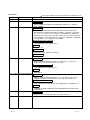
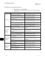
REVISIONS
The manual number is given on the bottom left of the back cover.
Print Date
Aug., 2002
Feb., 2003
Manual Number
SH (NA)-080350E-A First edition
SH (NA)-080350E-B Modifications
Revision
SAFETY PRECAUTIONS, About Manuals, Section 3.1.1, Section
6.4.4, INDEX
Jul., 2003
SH (NA)-080350E-C Modifications
This Manual's Use and Structure, About the Generic Terms and
Abbreviations, Product Composition, Chapter 1, Section 1.2, Section
3.1, 3.1.1, 3.1.2, 3.2.2, 3.2.5, 3.2.6, 3.5, 3.6, Section 4.2, Section 5.1.1,
Section 6.3.2, 6.4.3, 6.4.5, 6.4.6, 6.4.7, 6.4.8, 6.4.9, 6.4.10, 6.5, 6.5.3,
6.5.4, Section 7.1, Section 8.4, 8.5.1, 8.5.2, 8.6, Appendix 1, Appendix
4.4, Appendix 7.3, 7.4, Appendix 10, INDEX
Chapter/section No. change
From Section 5.1.2 to Section 5.1.3
Addition
Section 5.1.2
Model addition
QJ71FL71-T-F01, QJ71FL71-B5-F01
Model deletion
Jun., 2004
QJ71FL71-F01
SH (NA)-080350E-D Modifications
SAFETY PRECAUTIONS, Section 1.2, Section 3.1.1, 3.2.5, 3.5,
Section 6.2.7, 6.4.6, 6.4.8, 6.4.10, 6.5, 6.5.4
Chapter/section No. change
From Appendix 10 to Appendix 11
Addition
Jan., 2006
Appendix 10
SH (NA)-080350E-E Modifications
SAFETY PRECAUTIONS, Section 1.2, 1.4, Section 3.1.2, 3.2, 3.5,
Chapter 4, Section 5.1, Section 6.1.4, 6.2, 6.4, 6.5, Section 8.2
Chapter/section No. change
From Section 8.6 to Section 8.7, From Appendix 11 to Appendix 12
Addition
Compliance with the EMC and Low Voltage Directives, Section 8.6,
Appendix 11
Feb., 2006
SH (NA)-080350E-F Modifications
Section 3.1.1, 3.2.6, Section 6.4.6, 6.4.8, 6.4.10, 6.5.4
A-5
A-5
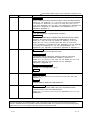
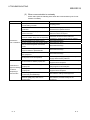
The manual number is given on the bottom left of the back cover.
Print Date
Manual Number
Jan., 2008 SH (NA)-080350E-G
Revision
Modifications
SAFETY PRECAUTIONS, About the Generic Terms and Abbreviations,
Section 1.2, 1.3, Section 3.1.1, 3.1.2, 3.2.2, to 3.2.6, 3.4, to 3.6, Section
4.2, Section 5.1, Section 6.1.2, 6.3.2, 6.2.7, 6.2.8, 6.3.2, 6.4.3, 6.4.4,
6.5.2, 6.5.4, Section 8.1, 8.3, 8.4, 8.5.1, 8.6, Appendix 2.3, Appendix 3.8,
Appendix 4.3, Appendix 5.1, Appendix 6.1, 6.3, Appendix 7.3, 7.4,
Appendix 9, Appendix 12
May., 2008 SH (NA)-080350E-H
Change of a term
"PLC" was changed to "programmable controller".
Modifications
SAFETY PRECAUTIONS, Compliance with the EMC and low voltage
directives, About the Generic Terms and Abbreviations, Section 2,
Section 3.1.1, 3.2.2 to 3.2.6, 3.5, Section 4.2, Section 5.1.1 to 5.1.3,
Section 6.1.1, 6.1.3, 6.2.1, 6.2.6 to 6.2.8, 6.3, 6.4.1, 6.4.3, 6.4.5 to
6.4.10, 6.5 Section 7.2, Section 8.3 to 8.5, Appendix 2.2 to 2.5, Appendix
3.1, 3.5, 3.6, 3.8, Appendix 4.1, 4.2, 4.4, 4.6, Appendix 5.1, 5.2,
Appendix 6.2, 6.3, Appendix 7, Appendix 9, Appendix 10, Appendix 12
Jan., 2009 SH (NA)-080350E-I
Model addition
QJ71FL71-T, QJ71FL71-B5, QJ71FL71-B2
Change of a term
The Manual's Use and Structure, About the Generic Terms and
Abbreviations, Product Composition, Chapter 1, Section 1.2,
Section 3.1.1, 3.1.2, 3.2.2, 3.2.5, 3.2.6, 3.5, 3.6, Section 5.1.1 to 5.1.3,
Section 6.2.8, 6.3.2, 6.4.3, 6.5, Section 8.4, 8.7, Appendix 1,
Appendix 6.1, Appendix 13
Chapter/section No. change
Appendix 3 to 12
Appendix 4 to 13
Addition
Appendix 2
Dec., 2009 SH (NA)-080350E-J
Change of a term
Section 1.2, 3.2.5, 6.2.8, 6.3.2, 6.4.10, 6.5.1, 6.5.2, 6.5.3, 6.5.4, 8.4,
Appendix 13
Addition
CONDITIONS OF USE FOR THE PRODUCT
Jul., 2012
SH (NA)-080350E-K
Change of a term
COMPLIANCE WITH EMC AND LOW VOLTAGE DIRECTIVES,
About the Generic Terms and Abbreviations,
Section 3.1.1, 3.1.2, 3.2.2, 3.5, 6.2.7, 6.4.4, Appendix 6.1, 7.2, 7.3, 13,
WARRANTY
Japanese Manual Version SH-080349-O
This manual confers no industrial property rights or any rights of any other kind, nor does it confer any patent
licenses. Mitsubishi Electric Corporation cannot be held responsible for any problems involving industrial property
rights which may occur as a result of using the contents noted in this manual.
© 2002 MITSUBISHI ELECTRIC CORPORATION
A-6
A-6
INTRODUCTION
Thank you for purchasing the MELSEC-Q series programmable controller.
Before using the equipment, please read this manual carefully to develop full familiarity with the functions
and performance of the Q series programmable controller you have purchased, so as to ensure correct use.
Please forward a copy of this manual to the end user.
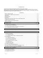
CONTENTS
SAFETY PRECAUTIONS..............................................................................................................................A- 1
CONDITIONS OF USE FOR THE PRODUCT .............................................................................................A- 4
REVISIONS ....................................................................................................................................................A- 5
INTRODUCTION............................................................................................................................................A- 7
CONTENTS ....................................................................................................................................................A- 7
COMPLIANCE WITH EMC AND LOW VOLTAGE DIRECTIVES ...............................................................A-11
The Manual's Use and Structure ...................................................................................................................A-12
About the Generic Terms and Abbreviations ................................................................................................A-15
Product Composition......................................................................................................................................A-17
1 INTRODUCTION
1.1
1.2
1.3
1.4
1- 1 to 1- 6
What is the FL-net (OPCN-2)? ............................................................................................................... 1Features of the FL-net (OPCN-2) ........................................................................................................... 1Frequently Asked Questions about the FL-net (OPCN-2)..................................................................... 1FL-net (OPCN-2) Version Information.................................................................................................... 1-
2
3
5
6
2 SAFETY PRECAUTIONS
2- 1 to 2- 2
3 FL-net MODULE
3- 1 to 3-55
3.1 System Configuration.............................................................................................................................. 3- 1
3.1.1 Applicable systems .......................................................................................................................... 3- 3
3.1.2 Equipment required when configuring the network......................................................................... 3- 7
3.2 Specifications .......................................................................................................................................... 3-12
3.2.1 General specifications...................................................................................................................... 3-12
3.2.2 Performance specifications.............................................................................................................. 3-12
3.2.3 FL-net module function list............................................................................................................... 3-14
3.2.4 I/O signals for the CPU module ....................................................................................................... 3-16
3.2.5 Buffer memory.................................................................................................................................. 3-22
3.2.6 Status data details............................................................................................................................ 3-40
3.3 Multiple CPU Systems ............................................................................................................................ 3-49
3.4 For Use with Q12PRH/Q25PRHCPU .................................................................................................... 3-49
3.5 How to Check the Function Version and Software Version .................................................................. 3-50
3.6 Functions and Names of Parts of FL-net Module .................................................................................. 3-53
4 MOUNTING THE FL-net MODULE
4- 1 to 4- 2
4.1 Mounting and Installation........................................................................................................................ 4- 1
4.2 Precautions when Handling.................................................................................................................... 4- 1
4.3 Installation Environment.......................................................................................................................... 4- 2
A-7
A-7
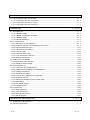
5 WIRING THE FL-net MODULE
5- 1 to 5- 5
5.1 Communication Cable Connections ....................................................................................................... 55.1.1 Connecting to QJ71FL71-B5(-F01) ................................................................................................. 55.1.2 Connecting to QJ71FL71-T(-F01) ................................................................................................... 55.1.3 Connecting to QJ71FL71-B2(-F01) ................................................................................................. 56 USAGE GUIDE
1
2
3
4
6- 1 to 6-101
6.1 About Ethernet ........................................................................................................................................ 6- 1
6.1.1 10BASE5 system ............................................................................................................................. 6- 1
6.1.2 10BASE-T/100BASE-TX system..................................................................................................... 6- 5
6.1.3 10BASE2 system ............................................................................................................................. 6- 5
6.1.4 Ethernet IP address ......................................................................................................................... 6- 6
6.2 FL-net (OPCN-2)..................................................................................................................................... 6- 7
6.2.1 Summary of FL-net (OPCN-2) ......................................................................................................... 6- 7
6.2.2 Number of modules connected and node numbers........................................................................ 6- 9
6.2.3 Data communication type ................................................................................................................ 6-10
6.2.4 Transmission data volume............................................................................................................... 6-11
6.2.5 Transfer cycles ................................................................................................................................. 6-12
6.2.6 Data area and memory .................................................................................................................... 6-12
6.2.7 Cyclic transmission and area........................................................................................................... 6-13
6.2.8 Message transmission ..................................................................................................................... 6-21
6.3 Setting the FL-net Module ...................................................................................................................... 6-35
6.3.1 Procedures up to operation.............................................................................................................. 6-35
6.3.2 Setting the GX Developer ................................................................................................................ 6-38
6.4 GX Configurator-FL................................................................................................................................. 6-42
6.4.1 Functions of GX Configurator-FL..................................................................................................... 6-42
6.4.2 Installing and uninstalling GX Configurator-FL................................................................................ 6-43
6.4.3 Handling precautions ....................................................................................................................... 6-43
6.4.4 Operating environment .................................................................................................................... 6-45
6.4.5 Common GX Configurator-FL operations ....................................................................................... 6-47
6.4.6 Operation overview .......................................................................................................................... 6-51
6.4.7 Starting the Intelligent function module utility.................................................................................. 6-52
6.4.8 Initial setting...................................................................................................................................... 6-54
6.4.9 Auto refresh setting .......................................................................................................................... 6-56
6.4.10 Monitoring/Test............................................................................................................................... 6-59
6.5 Programming........................................................................................................................................... 6-65
6.5.1 Initial processing............................................................................................................................... 6-67
6.5.2 Cyclic transmission........................................................................................................................... 6-70
6.5.3 Message transmission ..................................................................................................................... 6-72
6.5.4 Sample program............................................................................................................................... 6-91
7 MAINTENANCE AND INSPECTION
7- 1 to 7- 2
7.1 Maintenance and Inspection................................................................................................................... 7- 1
7.2 Removing the Module ............................................................................................................................. 7- 2
A-8
A-8
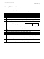
8 TROUBLESHOOTING
8- 1 to 8-16
8.1 Is It Really an Error? ............................................................................................................................... 8- 1
8.2 Solutions to General Network Problems ................................................................................................ 8- 2
8.3 FL-net (OPCN-2) General Precautions .................................................................................................. 8- 5
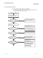
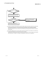
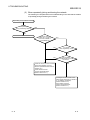
8.4 Troubleshooting Flowchart ..................................................................................................................... 8- 6
8.5 Errors and Their Solutions ...................................................................................................................... 8- 9
8.5.1 Confirming errors using the LEDs ................................................................................................... 8- 9
8.5.2 Confirming errors using error code.................................................................................................. 8-11
8.6 System Monitor ....................................................................................................................................... 8-15
8.7 H/W Information ...................................................................................................................................... 8-16
APPENDICES
App- 1 to App-60
Appendix 1 Transition from QJ71FL71-T/QJ71FL71-B5/QJ71FL71-B2 to QJ71FL71-T-F01/
QJ71FL71-B5-F01/QJ71FL71-B2-F01 .................................................................................App- 1
Appendix 2 Upgrading the Functions from the QJ71FL71-T/QJ71FL71-B5/QJ71FL71-B2 to the
QJ71FL71-T-F01/QJ71FL71-B5-F01/QJ71FL71-B2-F01 ...................................................App- 2
Appendix 2.1 Comparison of module functions....................................................................................App- 2
Appendix 2.2 Precautions when replacing from function version A to function version B..................App- 2
Appendix 2.3 Precautions when mixing modules with function versions A and B..............................App- 2
Appendix 3 Guide to System Configuration .............................................................................................App- 3
Appendix 3.1 Overview of Ethernet ......................................................................................................App- 3
Appendix 3.2 10BASE5 specifications ...............................................................................................App- 4
Appendix 3.3 10BASE-T/100BASE-TX specifications.........................................................................App- 5
Appendix 3.4 10BASE2 specifications .................................................................................................App- 6
Appendix 3.5 Other Ethernet specifications .........................................................................................App- 7
Appendix 4 Examples of System Configuration.......................................................................................App- 8
Appendix 4.1 Small-scale configuration ...............................................................................................App- 8
Appendix 4.2 Basic configuration..........................................................................................................App- 9
Appendix 4.3 Large-scale configuration ...............................................................................................App-10
Appendix 4.4 Long-distance distributed configuration .........................................................................App-11
Appendix 4.5 Local centralized configuration.......................................................................................App-12
Appendix 4.6 Local and long-distance dispersed configuration ..........................................................App-13
Appendix 4.7 Basic concepts of the FL-net (OPCN-2) system............................................................App-14
Appendix 4.8 Differences between conventional Ethernet and FL-net (OPCN-2)..............................App-14
Appendix 5 Network System Definitions ..................................................................................................App-15
Appendix 5.1 Communication protocol standards ...............................................................................App-15
Appendix 5.2 Communication protocol layer structure ........................................................................App-15
Appendix 5.3 FL-net (OPCN-2) physical layer .....................................................................................App-16
Appendix 5.4 FL-net (OPCN-2) IP address..........................................................................................App-16
Appendix 5.5 FL-net (OPCN-2) sub-net mask .....................................................................................App-17
Appendix 5.6 TCP/IP, UDP/IP communication protocol ......................................................................App-17
Appendix 5.7 FL-net (OPCN-2) port numbers......................................................................................App-17
Appendix 5.8 Data format for FL-net (OPCN-2)...................................................................................App-18
Appendix 5.9 FL-net (OPCN-2) transaction code ................................................................................App-20
A-9
A-9
Appendix 6 FL-net (OPCN-2) Network Control........................................................................................App-21
Appendix 6.1 FL-net (OPCN-2) token control ......................................................................................App-21
Appendix 6.2 FL-net (OPCN-2) enter and release...............................................................................App-32
Appendix 7 Network Components ............................................................................................................App-34
Appendix 7.1 List of Ethernet components...........................................................................................App-34
Appendix 7.2 10BASE5 components ...................................................................................................App-35
Appendix 7.3 10BASE-T/100BASE-TX components...........................................................................App-43
Appendix 8 Grounding the FL-net (OPCN-2) System .............................................................................App-45
Appendix 8.1 Summary of grounding the FL-net (OPCN-2) system ...................................................App-45
Appendix 8.2 Power supply wires and grounding ................................................................................App-46
Appendix 8.3 Power supply wiring and grounding for network equipment in the FL-net
(OPCN-2) system ...........................................................................................................App-47
Appendix 8.4 Mounting FL-net (OPCN-2) system network components ............................................App-48
Appendix 8.5 Wiring grounding wiring ducts and conduit ....................................................................App-49
Appendix 9 FL-net (OPCN-2) Installation Checklist.................................................................................App-50
Appendix 10 Profile Supplement ..............................................................................................................App-51
Appendix 11 Programming for Use of FL-net Module on MELSECNET/H Remote I/O Station ............App-56
Appendix 12 Cyclic Data Area Assignment Sheet...................................................................................App-58
Appendix 13 External Dimensions............................................................................................................App-59
INDEX
A - 10
Index- 1 to Index- 4
A - 10
COMPLIANCE WITH EMC AND LOW VOLTAGE DIRECTIVES
A - 11
(1)
Method of ensuring compliance
To ensure that Mitsubishi programmable controllers maintain EMC and Low
Voltage Directives when incorporated into other machinery or equipment, certain
measures may be necessary. Please refer to one of the following manuals.
• QCPU User's Manual (Hardware Design, Maintenance and Inspection)
• Safety Guidelines
(This manual is included with the CPU module or base unit.)
The CE mark on the side of the programmable controller indicates compliance
with EMC and Low Voltage Directives.
(2)
Additional measures
To ensure that this product maintains EMC and Low Voltage Directives, please
refer to one of the manuals listed under (1).
A - 11
The Manual's Use and Structure
How to use this manual
This manual is organized to provide information for specific usage applications for
the FL-net module (QJ71FL71-T-F01, QJ71FL71-B5-F01, QJ71FL71-B2-F01,
QJ71FL71-T, QJ71FL71-B5, QJ71FL71-B2). Refer to this manual for information
on the following topics.
(1) When you want a list of features and utilities . .
(a) To find out about features and functions
• The features of the FL-net module are provided in Chapter 1.
• The common functions, specifications and other details about FL-net are
provided in Chapter 3.
(b) When you want to know about the parts provided and component parts of
the network . . .
• The "Product Composition" at the front of Chapter 1 provides a list of the
parts provided in the package at the time of purchase of the FL-net
module.
• Section 3.1.2 provides a description of the system components for the FLnet module. The user is responsible for obtaining the parts and materials
required that have not been provided with the FL-net module.
(2) When you want to know the necessary procedures before starting
the FL-net module. . .
(a) To find out the start-up procedure
• Section 6.3.1 provides a summary of the procedures required up to
operating the FL-net module.
(b) To find out information about connecting to the FL-net (OPCN-2) network
system. . .
• Section 3.1.2 provides information about the equipment required for
connecting to the FL-net (OPCN-2) network system.
• Chapter 5 provides the connection methods for connecting to the FL-net
(OPCN-2) network system, listed by connected type.
(c) To find out the necessary procedures before starting the FL-net module. . .
• There are parameter setting screens from GX Developer for using the FLnet module. Section 6.3.2 provides information about the types of
parameter setting screens.
(d) To find out the method for confirming whether or not the FL-net module has
failed . . .
• Section 6.3.1(1) provides the self-diagnosis tests for the FL-net module.
(e) To find out the method for confirming whether or not there is an error in the
connection with corresponding equipment . .
• Section 8.2 (3) provides the method for confirming using the "PING"
command.
A - 12
A - 12
(3) When you want to know about the types of data communication
with detailed explanations. . .
(a) To find out about the types of data communications. . .
• Section 6.2.3 provides information about the types of data communication
for the FL-net module.
(b) To find out about the location of detailed explanations about each of the
communication methods . . .
• Section 6.2.7 provides information about cyclic transmissions and areas.
• Section 6.2.8 provides information about message transmissions.
(4) When you want to know about the program methods for
performing communication with the FL-net module. . .
• The beginning of Section 6.5 provides information about the procedures
for creating programs.
• Section 6.5.4 provides sample programs.
(5) When you want to know how to perform inspections and
maintenance on the FL-net module and how to remove and
replace components. . .
(a) To find out about inspections and maintenance. . .
• Section 7.1 provides information about inspection and maintenance of the
FL-net module.
(b) To find out about the procedure for removing and replacing components. . .
• Section 7.2 provides the operating procedure when replacing the FL-net
module and replacing the CPU.
(6) When you want to know how to confirm an errors and the methods
for responding to them. . .
(a) To find the meanings of the error codes . . .
• Chapter 8 provides the methods for troubleshooting and error
confirmation and also provides a description of the error codes and the
methods for responding to them.
(b) To find the storage locations of the error codes in the FL-net module. . .
• Chapter 8.5.2 provides information on the storage destination for the error
codes for the buffer memory.
A - 13
A - 13
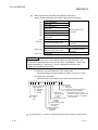
Structure of this manual
(1) Settings from GX Developer
(a) The FL-net module performs the parameter settings from GX Developer,
allowing the sequence program for performing communication with
corresponding equipment to be simplified.
(b) Section 6.3.2 provides a summary of the types of setting screens and the
setting items.
(c) Use Section 6.3.2 to set the relevant parameters and write them to the
programmable controller CPU for the FL-net module equipped station.
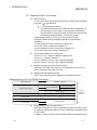
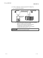
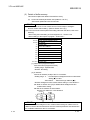
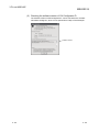
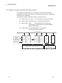
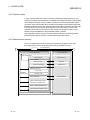
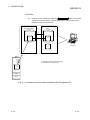
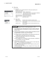
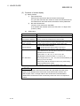
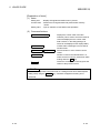
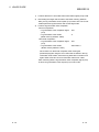
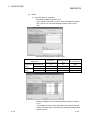
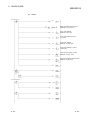
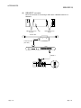
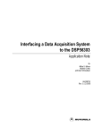
(2) Explanation of the GX Developer setting screen
In this manual, the intelligent function module switch settings from the GX
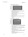
Developer are explained in the format shown below. (Section 6.3.2 (2))
Select the input format
for switches 1 to 5
Enter the operating
mode of the FL-net
module
Shows the GX Developer
Intelligent function module
switch setting screen.
Input the IP address
of the FL-net module
Shows the setting
contents of each switch.
Shows the setting
contents of the input
format.
A - 14
* The page illustrated above is provided for example only and is different from
any actual page.
A - 14
About the Generic Terms and Abbreviations
Unless otherwise stated, the following generic terms and detailed names are used
for explaining the QJ71FL71-T-F01, QJ71FL71-B5-F01, QJ71FL71-B2-F01,
QJ71FL71-T, QJ71FL71-B5, QJ71FL71-B2 type
FL-net (OPCN-2) interface module.
Generic terms/Abbreviations
Description of generic terms and abbreviations
Generic product name for the SWnD5C-GPPW-E, SWnD5C-GPPW-EA, SWnD5C-
GX Developer
GPPW-EV and SWnD5C-GPPW-EVA. ("n" is 4 or greater.)
"-A" and "-V" denote volume license product and upgraded product respectively.
GX Works2
Generic product name for SWnDNC-GXW2-E. (n: Version)
GX Configurator-FL
Personal computer
Generic product name for SWnD5C-QFLU and SWnD5C-QFLU-A. ("n" means version) "A" mean "volume license product" respectively.
IBM PC/AT or 100 % compatible personal computer.
Abbreviation for QJ71FL71-T-F01, QJ71FL71-B5-F01, QJ71FL71-B2-F01, QJ71FL71-T,
FL-net module
QJ71FL71-B5, QJ71FL71-B2 type
FL-net (OPCN-2) interface module.
Ethernet network system
Abbreviation for 10BASE2, 10BASE5, 10BASE-T/100BASE-TX network system.
Corresponding equipment
Personal computer, calculator, workstation (WS) or other device connected by FL-net
(OPCN-2) for data communication.
Generic term for Q00JCPU, Q00CPU, Q01CPU, Q02CPU, Q02HCPU, Q06HCPU,
Q12HCPU, Q25HCPU, Q02PHCPU, Q06PHCPU, Q12PHCPU, Q25PHCPU,
Q12PRHCPU, Q25PRHCPU, Q00UJCPU, Q00UCPU, Q01UCPU, Q02UCPU,
Q03UDCPU, Q04UDHCPU, Q06UDHCPU, Q10UDHCPU, Q13UDHCPU, Q20UDHCPU,
QCPU
Q26UDHCPU, Q03UDECPU, Q04UDEHCPU, Q06UDEHCPU, Q10UDEHCPU,
Q13UDEHCPU, Q20UDEHCPU, Q26UDEHCPU, Q50UDEHCPU, Q100UDEHCPU.
Basic model QCPU
Generic term for Q00JCPU, Q00CPU, Q01CPU.
High Performance model
QCPU
Generic term for Q02CPU, Q02HCPU, Q06HCPU, Q12HCPU, Q25HCPU.
Process CPU
Generic term for Q02PHCPU, Q06PHCPU, Q12PHCPU, Q25PHCPU.
Redundant CPU
Generic term for Q12PRHCPU, Q25PRHCPU.
Universal model QCPU
Generic term for Q00UJCPU, Q00UCPU, Q01UCPU, Q02UCPU, Q03UDCPU,
Q04UDHCPU, Q06UDHCPU, Q10UDHCPU, Q13UDHCPU, Q20UDHCPU,
Q26UDHCPU, Q03UDECPU, Q04UDEHCPU, Q06UDEHCPU, Q10UDEHCPU,
Q13UDEHCPU, Q20UDEHCPU, Q26UDEHCPU, Q50UDEHCPU, Q100UDEHCPU.
Generic term for the following:
R
R
Microsoft Windows 7 Starter Operating System,
R
R
R
R
Microsoft Windows 7 Home Premium Operating System,
R
R
Microsoft Windows 7 Professional Operating System,
R
Windows 7
Microsoft Windows 7 Ultimate Operating System,
R
R
Microsoft Windows 7 Enterprise Operating System
R
R
32-bit version and 64-bit version of Windows 7 are described as "Windows 7 (32-bit)
R
and "Windows 7 (64-bit) respectively.
Generic term for the following:
Windows Vista
R
R
R
R
R
Microsoft Windows Vista Home Basic Operating System,
R
R
Microsoft Windows Vista Home Premium Operating System,
Microsoft Windows Vista Business Operating System,
R
R
Microsoft Windows Vista Ultimate Operating System,
A - 15
A - 15
R
R
Microsoft Windows Vista Enterprise Operating System
Generic terms/Abbreviations
Windows XP
R
Description of generic terms and abbreviations
Generic term for the following:
R
R
Microsoft Windows XP Professional Operating System,
R
R
Microsoft Windows XP Home Edition Operating System
A - 16
A - 16
Product Composition
This unit is comprised of the following products.
Model Name
Product Name
Quantity
QJ71FL71-T-F01
QJ71FL71-T-F01 FL-net (OPCN-2) interface module
1
QJ71FL71-B5-F01
QJ71FL71-B5-F01 FL-net(OPCN-2)interface module
1
QJ71FL71-B2-F01
QJ71FL71-B2-F01 FL-net(OPCN-2) interface module
1
QJ71FL71-T
QJ71FL71-T FL-net (OPCN-2) interface module
1
QJ71FL71-B5
QJ71FL71-B5 FL-net (OPCN-2) interface module
1
QJ71FL71-B2
QJ71FL71-B2 FL-net (OPCN-2) interface module
1
SW0D5C-QFLU-E
GX Configurator-FL Version 1 (Single license product)
(CD-ROM)
1
SW0D5C-QFLU-E-A
GX Configurator-FL Version 1 (Volume license product)
(CD-ROM)
1
A - 17
A - 17
1 INTRODUCTION
MELSEC-Q
1 INTRODUCTION
1
This manual applies to the MELSEC-Q Series QJ71FL71-T-F01, QJ71FL71-B5-F01,
QJ71FL71-B2-F01, QJ71FL71-T, QJ71FL71-B5, and QJ71FL71-B2 type FL-net
(OPCN-2) interface modules (hereafter called the FL-net module) and provides
information about the specifications, procedures used up to operation, the methods of
data communication, inspection, maintenance and troubleshooting.
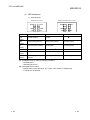
(1) FL-net (OPCN-2) versions
The FL-net module supports the following FL-net (OPCN-2) versions.
FL-net (OPCN-2) version
FL-net (OPCN-2) Version 2.00
FL-net (OPCN-2) Version 1.00
FL-net module
Ethernet standard
QJ71FL71-T-F01
10BASE-T/100BASE-TX
QJ71FL71-B5-F01
10BASE5
QJ71FL71-B2-F01
10BASE2
QJ71FL71-T
10BASE-T
QJ71FL71-B5
10BASE5
QJ71FL71-B2
10BASE2
(2) Coexistence of FL-net (OPCN-2) Version 2.00 and Version 1.00
Since there is no compatibility between FL-net (OPCN-2) Version 2.00 and FLnet (OPCN-2) Version 1.00, connections and communications are not allowed
between these versions.
This incompatibility applies to the case of connecting another manufacturer’s
product.
(3) Reuse of sequence programs and network equipment
Existing sequence programs and network equipment can be used between FLnet (OPCN-2) Version 2.00 and FL-net (OPCN-2) Version 1.00 modules.
1-1
1-1
1 INTRODUCTION
MELSEC-Q
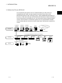
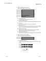
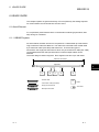
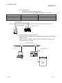
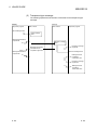
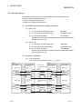
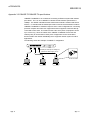
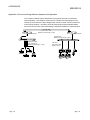
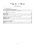
1.1 What is the FL-net (OPCN-2)?
FA-net (OPCN-2) (the generic term for a network featuring FA link protocol) is
standardized by the Japan FA Open Systems Promotion Group (JOP) of the
Manufacturing Science and Technology Center, a group affiliated with the Ministry of
Economy, Trade and Industry (the former Ministry of International Trade and Industry.)
The FA link protocol is intended for the FL-net to be used for data exchange between
various control modules in manufacture systems such as programmable controller,
robot controller (RC) and numerical control module (NC), and personal computers for
control.
Personal
computer
Personal
computer
Personal
computer
EWS
Server
Computer
WAN
Upper position LAN Ethernet (TCP/IP, UDP)
FL-net (OPCN-2) (Ethernet base control network)
Controller
Programmable
controller
Programmable
controller
Programmable
controller
Panel
controller
CNC
RC
Filed network
Device
1-2
Sensor
actuator
1-2
1
1 INTRODUCTION
MELSEC-Q
1.2 Features of the FL-net (OPCN-2)
The FL-net (OPCN-2) has the following features.
(1) Overall features of the FL-net (OPCN-2)
1-3
(a)
Realizes multi-vendor support
The FL-net (OPCN-2) can be interconnected to controllers, programmable
controllers and other devices for manufacturers' programmable controllers
or numerically controlled devices (CNC) and other devices that are very
different and provide control and monitoring.
(b)
Complies to standard specifications
It can use components commonly used for office automation equipment
using Ethernet network equipment (such as transceivers, hubs, cables and
LAN cards for Personal computer).
(c)
Designed for future speed increases
Anticipates future transmission speed increases 10 Mbps
Gbps.
100 Mbps
1
(d)
For large-scale networks
Up to 254 modules of equipment (nodes) can be connected.
(Of the 254 modules, 249 can be used for control. The remaining five
modules are assigned for failure diagnosis.)
(e)
Two types of communication functions to match the application
Supports both types of communication functions: cyclic transmission which
is a common memory function that allows each node to normally share the
same data and message communication function in which only the required
data is acquired when needed.
(f)
Large-capacity common memory
The common memory is large: 8 k bits + 8 k words.
(g)
Masterless method provides high reliability
Because there is no master and because the participation and release of
each node does not affect communication of remote nodes, any node can
freely turn the power supply on and off or perform maintenance.
1-3
1 INTRODUCTION
MELSEC-Q
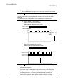
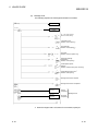
(2) Features of the FL-net module
(a)
Data consistency
In area 2 (word area), double word (32-bit) data consistency (the separation
prevention ( 1)) is guaranteed.
1: The separation prevention
The separation prevention is the data that has the meaning in a 2word (32-bits) for current value for the positioning module and it
uses the timing of cyclic transmission to prevent the new data and
old data from being separated in 1-word units (16-bits).
If the following conditions, 1) to 4), are met in common memory
assignment, double word (32-bit) data consistency is automatically
guaranteed.
1) The first address of area 1 (bit area) is multiples of 2.
2) The size of area 1 (bit area) is multiples of 2.
3) The first address of area 2 (word area) is multiples of 2.
4) The size of area 2 (word area) is multiples of 2.
(b)
The modules available for the cable used
QJ71FL71-T-F01 - Supports 10BASE-T/100BASE-TX
QJ71FL71-T - Supports 10BASE-T
QJ71FL71-B5-F01, QJ71FL71-B5 - Supports 10BASE5
QJ71FL71-B2-F01, QJ71FL71-B2 - Supports 10BASE2
(c)
Supports the PING command response function
When there is a PING command from a corresponding node, the FL-net
module responds to the PING command.
(d)
Equipped with self-diagnosis function
The FL-net module can perform Hardware test and self-return test.
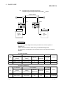
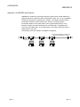
<Basic structure of FL-net (OPCN-2) protocol>
Application layer
Controller · Interface
FA Link protocol layer
Cyclic transmission
Cyclic transmission
Message transmission
Token function
Transport layer
UDP
Network layer
IP
Data Link layer
Ethernet
(ISO/IEC8802-3)
Physical layer
(e)
1-4
FL-net
(OPCN-2)
Protocol
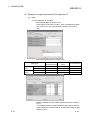
Easy setting by using GX Configurator-FL
Using GX Configurator-FL, which is separately available, can reduce steps
for sequence programs because on-screen configuration is available for the
FL-net module.
In addition, it makes checking of the modules’ settings and operations easy.
1-4
1 INTRODUCTION
MELSEC-Q
1.3 Frequently Asked Questions about the FL-net (OPCN-2)
The following are some of questions commonly asked about FL-net module (OPCN-2).
Please use them for your reference.
Question
1
What is Ethernet?
Answer
Ethernet is a specification for defining the types of cables that is used in a Local
Area Network (LAN). With Ethernet, data can be transferred among computers at
a communication speed of 10 Mbps to 100 Mbps. Currently, the Ethernet most
used for office applications is the 100 Mbps twisted pair cable (UTP). Ethernet
uses the software protocol that is sent out by many multi-vendors to make
communication possible.
2
What is FL-net (OPCN-2)?
FL-net (OPCN-2) is a network that connects FA controllers, such as
programmable controllers or numerical control devices (CNC) and performs highspeed interactive exchanging of control data among these controllers. The cables
and other components are the same as those used in Ethernet systems.
3
What is the difference between
Ethernet connects host computers, personal computer and other types of
FL-net (OPCN-2) and
controllers and is used for giving production instructions, collecting various
Ethernet?
production data and control applications. In addition, FL-net (OPCN-2) is used for
making connections among controllers and using it for the high-speed exchange
of controller data. When there is one controller module and when the FL-net
(OPCN-2) is mounted on both the Ethernet for the host and for among the
controllers, use extreme care not to mis-connect the cables.
4
How do you use the FL-net
The FL-net module is mounted to FA controllers such as programmable
(OPCN-2)?
controllers or numerical control devices (CNC) and by simply performing the link
allocation settings for the station number (node number) and common memory
(link register) in the same way as a "CPU link module" on a conventional
computer, the cyclic sending and receiving of data among the controllers can be
performed. Accordingly, no special communication program is required for the
programmable controller or other control devices. Moreover, no special
communication program is required for reading and rewriting programmable
controller memory or communication parameter data from the personal computer.
It should be noted that each controller will need a program if data transmission is
performed using message transmission interactively among the controllers.
5
6
What is protocol? Specifically,
Protocol consists of the rules necessary for communicating. FL-net (OPCN-2)
what protocol does FL-net
supports UDP/IP and uses the dedicated "FA Link Protocol" for FL-net (OPCN-2)
(OPCN-2) support?
for positioning on the upper layer.
Can FL-net (OPCN-2) be
The FL-net module mounted to FA controllers such as programmable controllers
connected to a conventional
and numerical control devices (CNC) have intelligent modules that have
personal computer?
processors in the boards. Ethernet cards are referred to as "dumb boards", which
means that they use a non-intelligent format so their use will depend on the
performance of the personal computer and how it is used. Generally speaking,
the use of the intelligent type FL-net (OPCN-2) board is recommended.
(Continued on next page)
1-5
1-5
1 INTRODUCTION
MELSEC-Q
(Continued from previous page)
Question
Answer
7
What is topology?
Network topology indicates the layout of the wiring. Generally speaking, there are
three main layouts: star (tree), bus and ring. It is probably easier to think of these
as logical arrangements rather than the physical layout of the cables. The
10BASE-T/100BASE-TX used on FL-net (OPCN-2) is star topology. 10BASE5 is
bus topology.
8
What is the relationship
between the type of network
cable and the length and
number of modules that can
be connected?
The following are some of the standards, characteristics and limitations of
Ethernet cable, which is the most commonly used type.
Note: Values shown in ( ) indicate that a repeater is used.
(1) 10BASE-T/100BASE-TX
Twisted pair cable (STP/UTP). The maximum transmission distance per
segment is 100 m (500 m). The maximum number of modules that can be
connected per segment is 254.
(2) 10BASE5
Thick coaxial cable (yellow cable). The maximum transmission distance per
segment is 500 m (2500 m). The maximum number of modules that can be
connected per segment is 100 (254).
(3) 10BASE-FL
Optical fiber cable. The maximum transmission distance per segment is 2000
m. The maximum number of modules that can be connected per segment is
254.
9
Are special Ethernet
specifications required for
systems using FL-net
(OPCN-2)?
No.
When constructing a FL-net (OPCN-2) system, uses Ethernet specifications
(IEEE802.3 standards). There are no special specifications.
10
How is connection with FL-net
(OPCN-2) made?
Different types of Ethernet media can be interconnected to Ethernet cable by
using devices such as repeaters and media conversion adapters. These products
are sold by a most vendors.
11
What is the best cables to use
when constructing a FL-net
(OPCN-2) system?
The following are the most commonly used cables.
• Trunk lines : 10BASE5 (Thick coaxial cable, yellow cable)
• Inside control panels and for office applications: 10BASE-T/100BASE-TX
(Twisted pair cable, STP/UTP category 5 or more)
• Locations with high-voltage power supplies or other types of electric noise:
10BASE-FL (optical fiber cable)
12
How do you set the IP address
for FL-net (OPCN-2)?
The FL-net (OPCN-2) IP address is network address: 192.168.250. Host number
(node number): 1 to 254 is standard. Note that node numbers 250 to 254 are
reserved for maintenance use.
13
What is the compatibility and
interconnectability of FL-net
(OPCN-2) compatible
equipment?
There is a certification organization for FL-net (OPCN-2) that performs
compatibility and interconnectability testing. Equipment that pass these tests are
issued a certificate to show that they are FL-net (OPCN-2) compatible equipment.
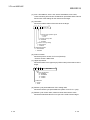
1.4 FL-net (OPCN-2) Version Information
The FL-net (OPCN-2) authorization version of the FL-net module can be confirmed
with the buffer memory (Address: 9CAH).
The FL-net (OPCN-2) protocol version of the FL-net module can be checked with the
buffer memory (Address: 9C9H).
(Refer to Section 3.2.6 (2).)
1-6
1-6
2 SAFETY PRECAUTIONS
MELSEC-Q
2 SAFETY PRECAUTIONS
The beginning of this manual contains "SAFETY PRECAUTIONS". Read and
understand them before using this product.
In addition, before using this product read this manual and all other related manuals
introduced in this manual. Always keep safety top priority when using this equipment.
2
2-1
2-1
2 SAFETY PRECAUTIONS
MELSEC-Q
MEMO
2
2-2
2-2
3 FL-net MODULE
MELSEC-Q
3 FL-net MODULE
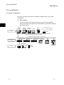
3.1 System Configuration
This section introduces the system configuration possible using FL-net module
combinations.
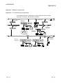
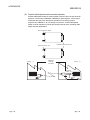
(1) Basic system
The FL-net module can communicate with FL-net (OPCN-2) compatible
personal computer and equipment. (Use dedicated FL-net (OPCN-2) wiring for
the Ethernet wiring.)
3
Personal
computer
Personal
computer
Personal
computer
EWS
Server
Computer
WAN
Upper position LAN Ethernet (TCP/IP, UDP)
FL-net (OPCN-2) (Ethernet base control network)
Controller
Programmable
controller
Programmable
controller
Programmable
controller
Panel
controller
CNC
RC
Filed network
Device
3-1
Sensor
actuator
3-1
3 FL-net MODULE
MELSEC-Q
(2) Mixed system
The following is the type of communication possible with mixed systems.
(a)
Cyclic transmissions
Data transmissions can be performed within FL-net (OPCN-2).
Communication with other networks can be performed by interchanging
the CPU module and using a sequence program.
(b)
Message transmissions (transient transmission)
Data transmissions can be performed within FL-net (OPCN-2).
Communication with other networks can be performed by interchanging
the CPU module and using a sequence program.
Ethernet
FL-net (OPCN-2)
MELSECNET/H
3-2
3-2
3
3 FL-net MODULE
MELSEC-Q
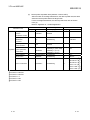
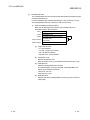
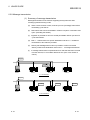
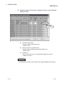
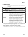
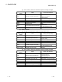
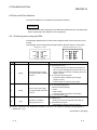
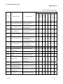
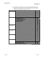
3.1.1 Applicable systems
This section describes the applicable systems.
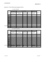
(1) Applicable modules and base units, and No. of modules
(a) When mounted with a CPU module
The table below shows the CPU modules and base units applicable to the
FL-net module and quantities for each CPU model.
Depending on the combination with other modules or the number of
mounted modules, power supply capacity may be insufficient.
Pay attention to the power supply capacity before mounting modules, and if
the power supply capacity is insufficient, change the combination of the
modules.
Applicable CPU module
CPU type
CPU model
Q00JCPU
Q00CPU
Q01CPU
Q02CPU
Q02HCPU
High
Performance
Q06HCPU
model QCPU
Q12HCPU
Q25HCPU
Q02PHCPU
Q06PHCPU
Process CPU
Q12PHCPU
Q25PHCPU
Q12PRHCPU
Redundant CPU
Q25PRHCPU
Q00UJCPU
Q00UCPU
Q01UCPU
Q02UCPU
Q03UDCPU
Q04UDHCPU
Q06UDHCPU
Q10UDHCPU
Q13UDHCPU
Universal model Q20UDHCPU
QCPU
Q26UDHCPU
Q03UDECPU
Q04UDEHCPU
Q06UDEHCPU
Q10UDEHCPU
Q13UDEHCPU
Q20UDEHCPU
Q26UDEHCPU
Q50UDEHCPU
Q100UDEHCPU
Safety CPU
QS001CPU
Basic model
QCPU
Programmable
controller CPU
3-3
No. of modules
1
Base unit
Main base unit
2
Extension base unit
Up to 8
Up to 24
Up to 64
Up to 64
Up to 53
Up to 8
Up to 24
Up to 36
Up to 64
N/A
3
3-3
3 FL-net MODULE
MELSEC-Q
Applicable CPU module
CPU type
CPU model
C Controller module
Q06CCPU-V
Q06CCPU-V-B
No. of modules
1
Base unit
Main base unit
2
Extension base unit
Up to 64
Q12DCCPU-V
: Applicable,
: N/A
1: Limited within the range of I/O points for the CPU module.
2: Can be installed to any I/O slot of a base unit.
3: Connection of extension base units is not available with any safety CPU.
REMARK
When using with a C Controller module, refer to the C Controller Module User’s
Manual.
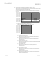
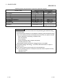
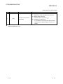
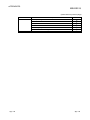
(b) Mounting to a MELSECNET/H remote I/O station
The table below shows the network modules and base units applicable to
the FL-net module and quantities for each network module model.
Depending on the combination with other modules or the number of
mounted modules, power supply capacity may be insufficient.
Pay attention to the power supply capacity before mounting modules, and if
the power supply capacity is insufficient, change the combination of the
modules.
Applicable network
module
Base unit
No. of modules
1
2
Main base unit of
Extension base unit of
remote I/O station
remote I/O station
QJ72LP25-25
QJ72LP25G
QJ72LP25GE
Up to 64
QJ72BR15
: Applicable,
1: Limited within the range of I/O points for the network module.
2: Can be installed to any I/O slot of a base unit.
: N/A
REMARK
The Basic model QCPU or C Controller module cannot create the MELSECNET/H
remote I/O network.
3-4
3-4
3 FL-net MODULE
MELSEC-Q
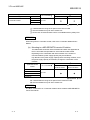
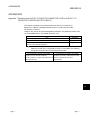
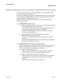
(2) Support of the multiple CPU system
When using the FL-net module in a multiple CPU system, refer to the QPU
User's Manual (Multiple CPU System) first.
3-5
(a)
Compatible FL-net module
1) QJ71FL71-T-F01, QJ71FL71-B5-F01, and QJ71FL71-B2-F01
These models have been first released as function version B,
supporting the multiple CPU system.
2) QJ71FL71-T, QJ71FL71-B5, and QJ71FL71-B2
Use a module of function version B.
(b)
Intelligent function module parameters
Write intelligent function module parameters to only the control CPU of the
FL-net module.
3-5
3 FL-net MODULE
MELSEC-Q
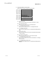
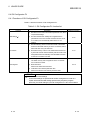
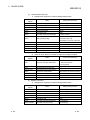
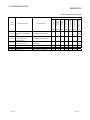
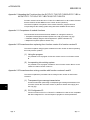
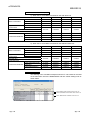
(3) Supported software packages
Relation between the system containing the FL-net module and software
package is shown in the following table.
GX Developer or GX Works2 is necessary when using the FL-net module.
Software version
GX Developer
Single CPU system
Version 7 or later
Multiple CPU system
Version 8 or later
Q02/Q02H/Q06H/
Single CPU system
Version 4 or later
Q12H/Q25HCPU
Multiple CPU system
Version 6 or later
Q00J/Q00/Q01CPU
Q02PH/Q06PHCPU
Q12PH/Q25PHCPU
Q12PRH/Q25PRHCPU
Q00UJ/Q00U/Q01UCPU
Q02U/Q03UD/Q04UDH/
Q06UDHCPU
Q10UDH/Q20UDHCPU
Q13UDH/Q26UDHCPU
Q03UDE/Q04UDEH/
Single CPU system
Multiple CPU system
Single CPU system
Multiple CPU system
Redundant CPU
Single CPU system
Multiple CPU system
Single CPU system
Multiple CPU system
Single CPU system
Multiple CPU system
Single CPU system
Multiple CPU system
Q10UDEH/Q20UDEHCPU
Q50UDEH/Q100UDEHCPU
Version 1.10L or later
Version 1.15R or later
SW0D5C-QFLU-E 00A or later
Version 8.68W or later
Version 1.13P or later
Version 7.10L or later
Version 8.45X or later
Version 1.87R or later
Version 1.14Q or later
Version 8.76E or later
Version 8.48A or later
Version 8.76E or later
Version 1.23Z or later
Version 1.15R or later
Cannot be used
Cannot be used
Version 1.31H or later
Version 6 or later
SW0D5C-QFLU-E 00A or later
Version 1.40S or later
Version 8.62Q or later
Version 8.68W or later
Multiple CPU system
Single CPU system
Multiple CPU system
Single CPU system
Multiple CPU system
If installed to MELSECNET/H remote I/O station
3-6
GX Works2
Single CPU system
Q06UDEH/Q13UDEH/
Q26UDEHCPU
GX Configurator-FL
Version 8.76E or later
3-6
3 FL-net MODULE
MELSEC-Q
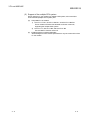
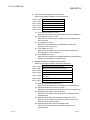
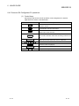
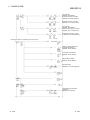
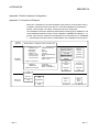
(4) Restrictions system configuration
Since the FL-net protocol of the FL-net (OPCN-2) Version 2.00 modules is
different from that of the FL-net (OPCN-2) Version 1.00 modules, the following
two types of modules cannot communicate each other.
FL-net(OPCN-2) Version 2.00 module
QJ71F71-F01, QJ71FL71-T-F01,
QJ71FL71-B5-F01, QJ71FL71-B2-F01
Version 2.00 products from other
manufacturers
FL-net(OPCN-2) Version 1.00 module
QJ71FL71-T, QJ71FL71-B5,
QJ71FL71-B2, Version 1.00 products from
other manufacturers
QJ71FL71-B5
FL-net(OPCN-2)
QJ71FL71-B5-F01
3-7
QJ71FL71-B5-F01
3-7
3 FL-net MODULE
MELSEC-Q
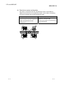
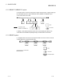
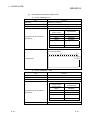
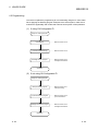
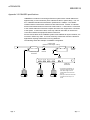
3.1.2 Equipment required when configuring the network
The following introduces the component equipment of the network.
Since installing the network requires the utmost of safety, always have the work done
by trained specialists.
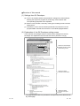
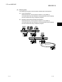
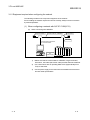
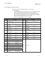
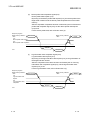
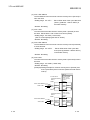
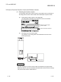
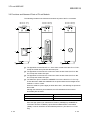
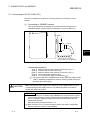
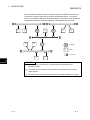
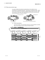
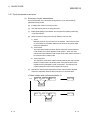
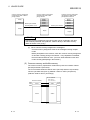
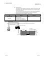
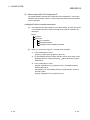
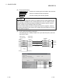
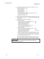
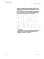
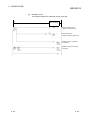
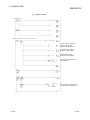
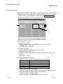
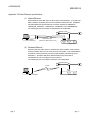
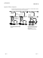
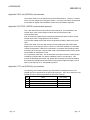
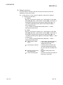
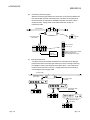
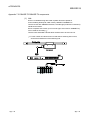
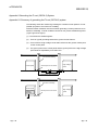
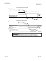
(1) When configuring a network with QJ71FL71-B5(-F01)
(a)
When connecting with 10BASE5.
N-type terminator
Coaxial cable for 10BASE5
Transceiver
AUI cable
DC
power supply
3-8
FL-net module
Corresponding equipment
for communication
1)
Makes sure that the coaxial cable for 10BASE5, N-type terminator,
transceiver, AUI cable (transceiver cable) all meet Ethernet standards.
2)
Use a transceiver with an operating SQE TEST (Signal Quality Error
Test) or heart beat.
3)
Use the power supply for the transceiver that satisfies the transceiver
and AUI cable specifications.
3-8
3 FL-net MODULE
MELSEC-Q
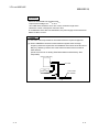
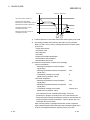
REMARK
Electrical characteristics of the transceiver
–6 %
+5%
to 15 V
• Input terminal voltage 12 V
• AUI cable direct resistance 40 Ω / km or less, maximum length: 50 m
• Maximum current consumption: 500 mA or less
In consideration of the above characteristics, the power supply for the transceiver
will be 13.28V to 15.75V.
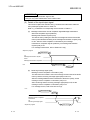
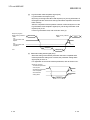
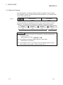
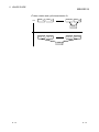
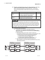
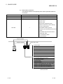
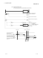
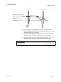
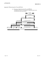
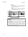
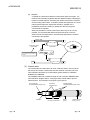
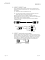
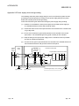
POINT
(1) Consult a network specialist for information about the required equipment.
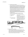
(2) When 10BASE5 is used and countermeasures against noise and highfrequency waves are required for the installation environment of the QJ71FL71B5(-F01), attaching a ferrite core to the transceiver side of the AUI cable is
often effective.
(Ferrite core used in our testing: ZCAT2032-0930 manufactured by TDK
Corporation)
QJ71FL71-B5(-F01)
AUI cable
DC
power supply
Ferrite core
Coaxial cable
for 10BASE5
Transceiver
3-9
3-9
3 FL-net MODULE
MELSEC-Q
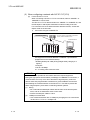
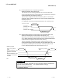
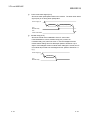
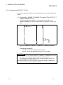
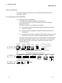
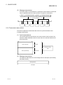
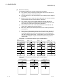
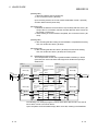
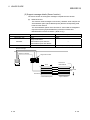
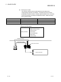
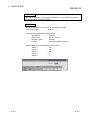
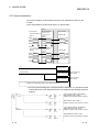
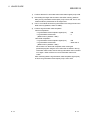
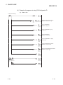
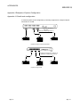
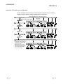
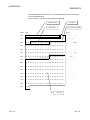
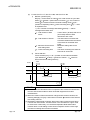
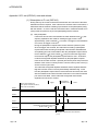
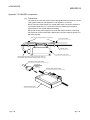
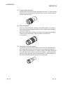
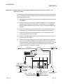
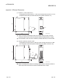
(2) When configuring a network with QJ71FL71-T(-F01)
(a)
For the QJ71FL71-T-F01
When connecting a QJ71FL71-T-F01 to a network, either a 10BASE-T or
100BASE-TX can be used.
The QJ71FL71-T-F01 detects whether it is 10BASE-T or 100BASE-TX, and
the full-duplex or half-duplex transmission mode according to the hub.
For connection to the hub without the auto detection function, set the halfduplex mode on the hub side.
1) Connection using the 100BASE-TX
Hub
Twisted pair cable
* For the number of cascade connection
levels, refer to Section 3.2.2.
External device
QJ71FL71-T-F01
Use equipment that meets IEEE802.3 100BASE-T specifications.
(Equipment from the HUB and below)
• Shielded twisted pair cable (STP) (straight cable), category 5 or
1
higher
• RJ45 jack.
• Hub for 100 Mbps.
1 A crossing cable cannot be used.
POINT
Consult a network specialist for information about the required equipment.
During the high-speed communication (100 Mbps) via 100BASE-TX connection, a
communication error may occur due to the effect of high frequency noise from
devices other than programmable controllers in a given installation environment.
The following are countermeasures on the QJ71FL71-T-F01 side to prevent the
effect of high frequency noise when constructing network systems.
(1) Wiring
• Do not bundle the twisted pair cables with the main circuit and the power
wires, and do not install them close to each other.
• Place the twisted pair cables in a duct.
(2) 10 Mbps communication
• Use a data transmission rate of 10 Mbps by changing the hub connected to
the QJ71FL71-T-F01 to a 10 Mbps hub.
3 - 10
3 - 10
3 FL-net MODULE
MELSEC-Q
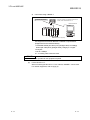
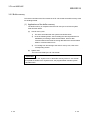
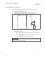
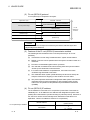
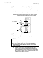
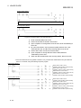
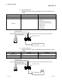
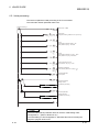
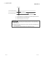
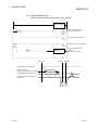
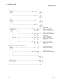
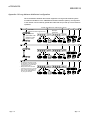
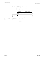
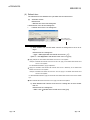
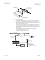
2)
Connection using 10BASE-T
Hub
Twisted pair cable
* For the number of cascade connection
levels, refer to Section 3.2.2.
External device
QJ71FL71-T(-F01)
Use equipment that meets IEEE802.3 10BASE-T specifications.
(Equipment from the HUB and below)
• Unshielded twisted pair cable (UTP) (straight cable) or shielded
*1
twisted pair cable (STP) (straight cable), category 3 or higher
• RJ45 jack
• Hub for 10 Mbps
1 A crossing cable cannot be used.
POINT
Consult a network specialist for the equipment required.
(b)
3 - 11
For the QJ71FL71-T
When connecting the QJ71FL71-T to a network, 10BASE-T can be used.
For network equipment, refer to (2) (a) 2).
3 - 11
3 FL-net MODULE
MELSEC-Q
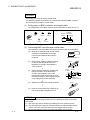
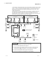
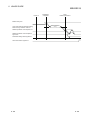
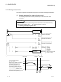
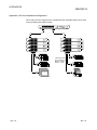
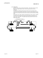
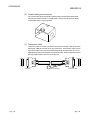
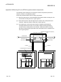
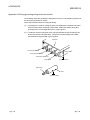
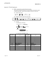
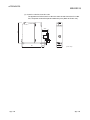
(3) When configuring a network with QJ71FL71-B2(-F01)
Connection using 10BASE2
Terminator
RG58A/U coaxial cable
or RG58C/U coaxial cable
Corresponding
communication
equipment
1)
T-shape connector
FL-net module
(a)
Use devices that meet the standards of IEEE802.3 and 10BASE2.
• RG58A/U or RG58C/U (coaxial cable 50 )
• BNC-type Terminator (product equivalent to 221629-4
manufactured by Tyco Electronics AMP K. K.)
• T-shaped adapter (product equivalent to UG-274/U(15)
manufactured by Hirose Electric Co., Ltd.)
POINT
Consult a network specialist for the equipment required.
3 - 12
3 - 12
3 FL-net MODULE
MELSEC-Q
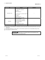
3.2 Specifications
This section explains the FL-net module performance specifications and transmission
specifications.
3.2.1 General specifications
For the general specifications for the FL-net module, refer to the user’s manual for the
CPU module that is to be used.
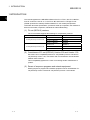
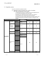
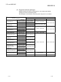
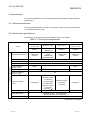
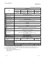
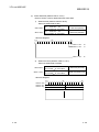
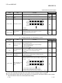
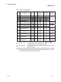
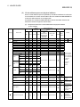
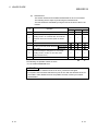
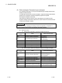
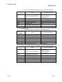
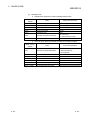
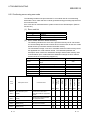
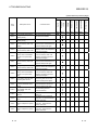
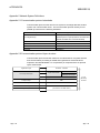
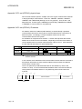
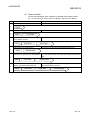
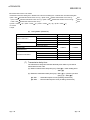
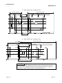
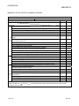
3.2.2 Performance specifications
The following are the performance specifications of the FL-net module.
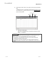
Table 3.1 Performance specifications
Specifications
Items
Data transmission speed
QJ71FL71-B5-F01/
QJ71FL71-B5
QJ71FL71-T-F01
QJ71FL71-T
QJ71FL71-B2-F01/
QJ71FL71-B2
10BASE5
10BASE-T/
100BASE-TX
10BASE-T
10BASE2
10Mbps (Half
duplex)
10Mbps (Half
duplex)
100Mbps (Full
duplex/Half duplex)
10Mbps (Half
duplex)
10Mbps (Half
duplex)
Transmission method
Base band
Electric interface
IEEE802.3 standard (CSMA/CD standard)
Transmission specifications
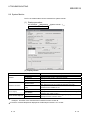
Transmission protocol
UDP/IP FA link protocol
Maximum distance
between nodes
2500m
—
925m
Maximum segment length
500m
100m
185m
Maximum number of
nodes in system
Maximum number of
nodes
Minimum node interval
Cyclic data volume
Message data volume
254
100/segment
2.5m
For 10BASE-T,
Maximum 4 bases
for Cascade
1
connection ( )
For 100BASE-TX,
Maximum 2 bases
for Cascade
1
connection ( )
Maximum 4 bases
for Cascade
connection
—
30/segment
0.5m
Maximum (8 k bits + 8 k words)/system
Maximum (8 k bits + 8 k words)/node
Maximum 1024 bytes
(Continued on next page)
3 - 12
3 - 12
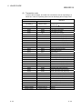
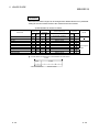
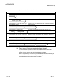
3 FL-net MODULE
MELSEC-Q
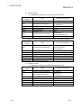
(Continued from previous page)
Specifications
QJ71FL71-B5-F01/
Items
QJ71FL71-B5
10BASE5
Transmission specifications
Link data specifications
Common memory area
Virtual address space and
physical memory
Error log memory area
QJ71FL71-T-F01
QJ71FL71-T
QJ71FL71-B2-F01/
10BASE-T/
10BASE-T
100BASE-TX
Area 1 (bit area): 8 k bits
Area 2 (word area): 8 k words
QJ71FL71-B2
10BASE2
—
512 words
Bit area: 2 k bits
Word area: 2 k words
QJ71FL71-B5-F01, QJ71FL71-T-F01, QJ71FL71-B2-F01: 128 words
QJ71FL71-B5, QJ71FL71-T, QJ71FL71-B2: 96 words
Status memory area
Local node network
parameter setting area
Other node network
parameter setting area
Network parameter
acquisition area
Device profile memory
area
Message area (Transient
area)
2048 words
512 words
512 words
Maximum 1024 bytes
2 (1 for each of transmit and receive)
500 ms or less
Message transmission
(1:1 Arrival time of one-way message)
New participation: Start time = 3000 + (Minimum node number/
8 remaining)
Token start time
4 + 1200ms
Halfway participation: Participation time = Refresh cycle
local node number
Refresh time
Refer to "Appendix 6.1 (6)".
Transmission delay time
Refer to "Appendix 6.1 (7)".
Number of input/output points
5VDC internal current
consumption
Noise resistance
Voltage resistance
Insulation resistance
32 points (I/O assignment: intelligent)
0.50A
0.50A
0.60A (
2
)
According to the power supply specifications of the station to which the FL-net module is
mounted.
External dimensions
Weight
3+
4ms
98 (3.86 in.) (H)
0.12kg
27.4 (1.08 in.) (W)
0.11kg
90 (3.54 in.) (D)mm
0.13kg (
2
)
1 : This number applies when a repeater hub is used.
For the number when a switching hub is used, consult the manufacturer of the switching hub.
2 : The 5VDC internal current consumption and weight of the product whose first 5 digits of serial No. are
05079 or earlier are as follows:
• 5VDC internal current consumption: 0.70A
• Weight: 0.14kg
3 - 13
3 - 13
3 FL-net MODULE
MELSEC-Q
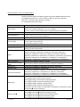
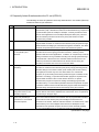
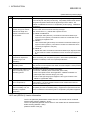
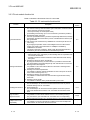
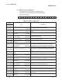
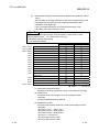
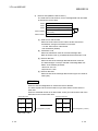
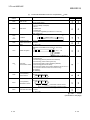
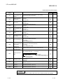
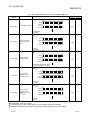
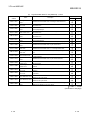
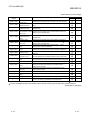
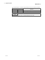
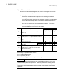
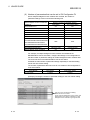
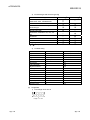
3.2.3 FL-net module function list
Table 3.2 shows the function list of the FL-net module.
Table 3.2 FL-net module functions list
Function
Cyclic transmission
Message transmission
Self diagnosis function
Ping command
response function
Multiple CPU function
compatibility
Reference
section
Description
(1) Communication of large data volume
The common memory method enables cyclic transmission of data as follows.
• Area 1 (bit area): 8 k bits (512 words)
• Area 2 (word area): 8 k words (8192 words)
(Transmitting and receiving up to 8. 5 k words/node cyclic data is possible.)
(2) Guaranteed refresh cycle time
Since the permissible refresh cycle time is dynamically determined, message
transmission (transient transmission) can be controlled with the refresh cycle
time guaranteed.
(3) High-speed cyclic transmission by 100BASE-TX connection (the QJ71FL71T-F01 only)
By changing the operation mode in the intelligent function module switch
setting, high-speed cyclic transmission at 100Mbps is available by
100BASE-TX connection.
This function has been certified by JEMA (Japan Electrical Manufacturer’s
Association), and can be used from the first released products.
(1) Transparent message transmission
• Message data (up to 1024 bytes) for the message area of a specified node
can be sent and received.
• Possible to send and receive transaction codes other than those used by
the system.
(2) Reading and writing of data in word blocks.
By using the virtual memory access method, it is possible to read and write
the virtual address space data assigned by each manufacturer in word units.
(3) Message return data response
It is possible to return the received data as-is whenever a message return
command is received.
(4) Reading of the network parameters
It is possible to read the network parameters for each node (such as vendor
name, token monitoring time, etc.).
(5) Reading and clearing of log information
It is possible to read and clear the communication log information held by
each node.
(6) Reading of device profile
It is possible to read the device profile data held by each node.
(1) Hardware test
The GX Developer can be used to set the hardware test mode to perform
hardware testing of the FL-net module.
(2) Self-loopback test
The GX Developer can be used to set the loopback test mode to perform
tests of the send/receive functions of FL-net module and the status of the
lines.
(1) Ping command compatibility
It is possible to confirm the IP address of the FL-net module by issuing a
ping command to your local station FL-net module from a corresponding
device (personal computer, etc.) connected to the FL-net (OPCN-2) network.
(1) Multiple CPU functions
It is possible to control by optional CPU modules, even when multiple card
CPU modules are mounted to the same base unit.
6.2
6.2
6.3.1
8.2(3)
-
(Continued on next page)
3 - 14
3 - 14
3 FL-net MODULE
MELSEC-Q
(Continued from previous page)
Function
Description
Reference
section
(1) Initial setting
Network parameter for common memory assignments, monitoring time and
others can be set by GX Configurator-FL.
Parameter setting by
GX Configurator-FL
(2) Auto refresh setting
It is possible to perform cyclic data auto refresh.
6.4
(3) Monitor/test
The buffer memory and I/O signals of the FL-net module can be monitored
and tested.
3 - 15
3 - 15
3 FL-net MODULE
MELSEC-Q
3.2.4 I/O signals for the CPU module
The section explains the input/output signals for the FL-net module.
(1) I/O signal list
The I/O signal assignments shown are based on the case where the start I/O No.
of the FL-net module is "0000" (mounted to slot 0 of a main base unit).
Device X denotes an input signal from the FL-net module to the CPU module.
Device Y denotes an output signal from the CPU module to the FL-net module.
Table 3.3 lists the I/O signals used for the CPU module.
Table 3.3 I/O signal list for the CPU module
Signal direction: CPU module
X00
FL-net module
Signal name
Input No.
Message transmission normal completion signal
ON: Normal completion
OFF: —
Signal direction: CPU module
Y00
FL-net module
Signal name
Output No.
Message transmission request
ON: Request
OFF: —
Message transmission abnormal completion signal
X01
X02
X03 to
X0F
X10
X11
ON: Abnormal completion
ending
Receiving message signal
ON: Receiving
X13
X14
X15
ON: Completed
Use prohibited
ON: Error
ON: Enter
X1B
Use prohibited
X1F
Message receive completion confirmation
ON: Request
OFF: —
Use prohibited
Network parameter write request
ON: Request
OFF: —
Network parameter/join node information read request
Y11
ON: Request
Y13
Y14
Y15
OFF: —
Use prohibited
Device profile read request
ON: Request
OFF: —
Log information clear request
ON: Request
OFF: —
Log information read request
ON: Request
OFF: —
OFF: Normal
Token enter status signal
Use prohibited
X1E
OFF: —
Use prohibited
Parameter setting status signal
X1A
X1D
OFF: —
Log information read completion signal
X17
X1C
OFF: —
Log information clear completion signal
ON: Completed
Y10
Y12
Device profile read completion signal
ON: Completed
Y02
OFF: —
Use prohibited
Use prohibited
X19
OFF: —
Network parameter/join node information read
completion signal
ON: Completed
Y01
Y03 to
Y0F
Network parameter write completion signal
X16
X18
OFF: No signal received
Use prohibited
ON: Completed
X12
OFF: —
OFF: Leave
Module ready
ON: Preparation completed
Y16
to
Y1F
Use prohibited
OFF: In initialization
Use prohibited
Use prohibited
Watchdog timer error detection signal
ON: Detected
3 - 16
OFF: Not detected
3 - 16
3 FL-net MODULE
MELSEC-Q
IMPORTANT
Do not set any "use-prohibited" signal to ON.
Doing so may cause malfunctions of the CPU module.
(2) Details of the input/output signal
This section explains the ON/OFF timing, conditions and other items related to
the input/output signals shown in Table 3.3
Data in ( ) indicates the corresponding device number in Table 3.3
(a)
Message transmission normal completion signal/Message transmission
abnormal completion signal (X00/X01)
Message transmission request (Y00)
The data is sent by setting the data in the message send area of the buffer
memory beforehand and setting of the message transmission request (Y00)
to ON. After the send completion confirmation by the message
transmission completion signals (X00/X01), set message transmission
request (Y00) to off.
For message transmission, refer to Section 6.5.3 (5).
Sequence program
Data transfer
Y0
Message transmission request
X0/X1
Message transmission completion
Line
Message data
ACK
(b)
Receiving message signal (X02)
Message receive completion confirmation (Y02)
The data from other nodes is set in the message received area of the buffer
memory and the receiving message signal (X02) is set to on.
After the message data has been transferred to the device (read), set the
message receive completion confirmation (Y02) to on.
After confirming that the receiving message signal (X02) is off, set the
message receive completion confirmation (Y02) to off.
For message receive, refer to Section 6.5.3 (5).
Line
Message data
ACK
Y2
Messege receive completion
confirmation
X2
Receiving message signal
Sequence program
3 - 17
Data transfer
3 - 17
3 FL-net MODULE
MELSEC-Q
(c)
Network parameter write completion signal (X10)
Network parameter write request (Y10)
The data is set in the network parameter area of its local node buffer
memory beforehand and the network parameter is registered by setting the
network parameter write request (Y10) to on.
After the write completion has been confirmed by the on of the network
parameter write completion signal (X10), set the network parameter write
request (Y10) to off.
For registration of local node network parameters, refer to Section 6.5.1.
Sequence program
Data transfer
Y10 network
parameter write request
X10 network
parameter write completion
Registration
(d)
Network parameter/join node information read completion signal (X11)
Network parameter/join node information read request (Y11)
By turning on the network parameter/join node information read request
(Y11), data of the target node are read out into the network parameter/join
node information acquisition area of the buffer memory.
After the acquisition completion has been confirmed by the on of the
network parameter/join node information read completion signal (X11), set
the network parameter/join node information read request (Y11) to off.
For the network parameter read, refer to Section 6.5.3 (1).
Sequence program
Buffer memory address
: 983H
Network parameter/join node
information read request
Buffer memory address
: 9D3H
Node number
Result
X11
Network parameter/join node
information read completion
completion
Request
Response
Line
POINT
The switching of network parameter/join node information reading is distinguished
by buffer memory address 983H . . . b15. (Refer to Section 3.2.6.(2))
0: Read network parameter data
1: Read join node data
3 - 18
3 - 18
3 FL-net MODULE
MELSEC-Q
(e)
Device profile read completion signal (X13)
Device profile read request (Y13)
By turning on the device profile read request (Y13), the device profile of the
target node is read out into the device profile acquisition area of the buffer
memory.
After the acquisition completion has been confirmed by the on of the device
profile read completion signal (X13), set the device profile read request
(Y13) to off.
For the device profile read, refer to Section 6.5.3 (2).
Sequence program
Buffer memory address
Node number
: 984H
Y13
Device profile read request
Buffer memory address
: 9D4H
Result
X13
Device profile read completion
Request
Response
Line
(f)
Log information clear completion signal (X14)
Log information clear request (Y14)
By turning on the log information clear request (Y14), the log information of
the target node are cleared.
After the completion of the clear has been confirmed by the on of the log
information clear completion signal (X14), set the log information clear
request (Y14) to off.
For the log information clear, refer to Section 6.5.3 (4).
Sequence program
Buffer memory address
: 985H
Y14
Log information clear
request
Buffer memory address
: 9D5H
Node number
Result
X14
Log information clear
completion
Request
Line
3 - 19
Response
3 - 19
3 FL-net MODULE
MELSEC-Q
(g)
Log information read completion signal (X15)
Log information read request (Y15)
By turning on the log information read request (Y15), the log information of
the target node are read out into the log information acquisition area of the
buffer memory.
After the completion of the acquisition has been confirmed by the on of the
log information read completion signal (X15), set the log information read
request (Y15) to off.
For the log information read, refer to Section 6.5.3 (3).
Sequence program
Buffer memory address
: 986H
Y15
Log information read
request
Buffer memory address
: 9D6H
Node number
Result
X15
Log information read
completion
Request
Response
Line
(h) Parameter setting status signal (X18)
When the writing of the network parameter has been completed and a
network parameter setting error is issued, the parameter setting status
signal (X18) is set to on.
For registration of local node network parameters, refer to Section 6.5.1.
Sequencer program
Y10 Network parameter
write request
X10 Network parameter
write completion
X18 Parameter
setting status
Error
Request
3 - 20
3 - 20
3 FL-net MODULE
MELSEC-Q
(i)
Token enter status signal (X19)
Shows the token participation status to the network. The token enter status
signal (X19) is on during token participation.
Power supply on
Initialization
Token participation
X1C
Module ready
X19
Token enter status
(j)
Module ready (X1C)
Shows the results of the initialization of the FL-net module.
If the initialization is normal, module ready (X1C) is set to on.
If module ready (X1C) does not come on, use the intelligent function
module switch settings from GX Developer (Refer to Section 6.3.2) to
adjust. If the intelligent function module switch settings are normal, the FLnet module will proceed to its self-diagnostic test. (Refer to Section 6.3.1
(1).)
Power supply on
Initialization
X1C
Module ready
3 - 21
3 - 21
3 FL-net MODULE
MELSEC-Q
3.2.5 Buffer memory
This section introduces the CPU module in the FL-net module and buffer memory used
for handling its data.
(1) Applications of the buffer memory
The buffer memory is comprised of an area for use by the user and a system
area as shown below.
(a)
(b)
Area for use by user
1)
This is the area other than the system area shown below.
2)
It has the following areas: area for setting the various parameters for
initialization processing or data communication, area for data
communication and an area for storing data about the communication
status or communication errors.
3)
For reading from and writing to the area for use by user, refer to the
corresponding section.
System area
The is the area used by the FL-net module.
Important
Never write data to the "System Area" of the buffer memory for the FL-net module.
If any data are written to the "System Area", the programmable controller system
will malfunction.
3 - 22
3 - 22
3 FL-net MODULE
MELSEC-Q
(2) Buffer memory assignment
The buffer memory is comprised of 1 address 16 bits.
The following is the overall structure of the buffer memory.
<Bit structure diagram>
b15 b14 b13 b12 b11 b10
b9
b8
b7
b6
b5
b4
b3
b2
b1
b0
Table 3.4 shows the buffer memory list.
Table 3.4 Buffer memory list
Address
Item
Decimal
(Hexadecimal)
0 to 127
(0 to 7FH)
128 to 2175
Description
Local node network parameter area
Set network parameters of the local node.
(128 words)
Other node network parameter area
(80 to 87FH)
Stores network parameters of the other nodes joining the
(2048 words) network.
2176 to 2303
System area
(880 to 8FFH)
2304 to 2431 Status data area
(900 to 97FH) Bit area: 2 k bits
(128 words)
(128 words)
2432 to 4479 Status data area
(980 to 117FH) Word area: 2 k words
4480 to 4607
(1180 to 11FFH)
System area
(2048 words)
(128 words)
—
Stores status data bit data.
Stores status data word data.
—
After execution of message transmission, the network
4608 to 5119 Network parameter/join node information
parameter/join node information read, this area stores the
(1200 to 13FFH) acquisition area
(512 words)
network parameter/join node information of the target node.
5120 to 5631
(1400 to 15FFH)
After execution of message transmission, the device profile
Device profile acquisition area (512 words) read, this area stores the device profile data of the target
node.
5632 to 6143 Log information acquisition area
(512 After execution of message transmission, the log information
(1600 to 17FFH) words)
6144 to 7167
(1800 to 1BFFH)
System area
read, this area stores the log information of the target node.
(1024 words)
—
7168 to 7679 Cyclic data area
(1C00 to 1DFFH) Area1: 8 k bits
Set bit cyclic data of the local node.
(512 words) Stores bit cyclic data of the other nodes.
7680 to 8191
System area
(1E00 to 1FFFH)
(512 words)
8192 to 16383 Cyclic data area
(2000 to 3FFFH) Area 2: 8 k words
16384 to 24575
(4000 to 5FFFH)
System area
—
Set word cyclic data of the local node.
(8192 words) Stores word cyclic data of the other nodes.
(8192 words)
—
24576 to 25599 Message data
(6000 to 63FFH) Send area
(1024 words)
25600 to 26623 Message data
(6400 to 67FFH) Receiving area
Stores data received by transparent type message
(1024 words) transmission.
26624 to 32767
(6800 to 7FFFH)
3 - 23
System area
(6144 words)
Set send data for transparent type message transmission.
—
3 - 23
3 FL-net MODULE
MELSEC-Q
(3) Details of buffer memory
This section explains the details of the buffer memory.
(a)
Local node network parameter area (Address: 0 to 7FH)
Set network parameters of the local node.
POINT
(1) The IP address of the FL-net module is set in GX Developer’s intelligent
function module switch setting. (Refer to Section 6.3.2 (2).)
(2) For the local node network parameter setting other than the above, refer to the
following:
• When using the initial setting of GX Configurator-FL: Section 6.4.8
• When setting on the sequence program: Section 6.5.1
0 to 4H
Node name (Equipment name)
5 to 6H
IP address
7H
System area
8H
Area 1 first address
9H
Area 1 size
AH
Area 2 first address
BH
Area 2 size
CH
Token monitoring time out time
DH
Minimum permissible frame interval
EH
Message data unit selection
F to 7FH
System area
[1] Node name (Equipment name)
Sets node name (Equipment name)
• Setting range : Optional data
• Default : No setting
[2] IP address
Sets the IP address (32 bit) of the FL-net module.
• Setting range : 0 · · · GX Developer’s intelligent function module switch
setting ( 1) is valid
: Other than 0 · · · Sets 32 bit logic address ( 2)
• Default: Intelligent function module switch setting or "192.168.250.1"
1: Refer to Section 6.3.2.(2) for details about intelligent function
module switch setting.
2: Set the IP address as shown below.
When the IP address is "192.168.250.2"
250(FA )
2(02 )
5
FA
02
6
C0
A8
192(C0 )
168(A8 )
POINT
There will be double intelligent function module switch settings in relation to the IP
address, but the value that has been set in the network parameter area will become
the enabled IP address for the FL-net module.
3 - 24
3 - 24
3 FL-net MODULE
MELSEC-Q
[3] Area 1 first address
The first address of the local node common memory area 1 (bit area) is
set in this area.
• Setting range: 0 to 1FFH · · · Set an offset value of the cyclic data area
(Area 1) (Address: 1C00 to 1DFFH) in
the buffer memory.
• Default : No setting
[4] Area 1 size
The size of the local node common memory area 1 (bit area) is set in
this area. Set the area 1 size in units of one word (16 bits).
• Setting range : 0 to 200H (1 word units)
(Set "2H" when specifying the size for 32 bits.)
• Default : No setting
[5] Area 2 first address
The first address of the local node common memory area 2 (word area)
is set in this area.
• Setting range: 0 to 1FFFH · · · Set an offset value of the cyclic data
area (Area 2) (Address: 2000 to 3FFFH)
in the buffer memory.
• Default : No setting
[6] Area 2 size
The size of the local node common memory area 2 (word area) is set in
this area.
• Setting range : 0 to 2000H (1 word units)
• Default : No setting
(Example) Setting example for common memory area 1 (bit area) and
area 2 (word area) of the local node (When the local node is
node 3)
Node 3
FL-net circuit
FL-net module
Buffer memory
Cyclic data area
(area 1)
Common memory
area 1
0000H
1C00H
0020H
Node 3
002FH
1C20H
Node 3
1C2FH
01FFH
1DFFH
Area 1 first address
Area 1 size
10H
Buffer memory
Cyclic data area
(area 2)
Common memory
area 2
0000H
2000H
0200H
Node 3
02FFH
2200H
Node 3
22FFH
1FFFH
3FFFH
Area 2 first address
Area 2 size
3 - 25
100H
3 - 25
3 FL-net MODULE
MELSEC-Q
[7] Token monitoring time out time
Sets the monitoring time from the local node address token receive
signal to the next node token transfer.
(If the token is held by another node, it monitors the time up to the
release of the token by the node holding the token.)
• Setting range : 1 to 255 (1 ms units)
• Default : 50
[8] Minimum permissible frame interval
Sets the time from local node address token receive signal to the
number of frames until local node sends.
In addition, it can also be used for message sending or frame interval
time for frame division.
• Setting range : 0 to 50 (100 μ s units)
• Default : 0
[9] Message data unit selection
Sets the unit for when message data is handled.
• Setting range : 0 · · · Word unit
: 1 · · · Byte unit
• Default: 0
Important
Never write data to the "System Area" of the buffer memory for the FL-net module.
If writing of data is performed to the "System Area", the programmable controller
system will malfunction.
POINT
Because this area is also used when the GX Configurator-FL is used, it can be
operated by sequence program settings if there is conflict with the sequence
program.
3 - 26
3 - 26
3 FL-net MODULE
MELSEC-Q
(b)
Other node network parameter area (address: 80 to 87FH)
Stores network parameters of the other nodes joining the network.
80H
Area 1 first address
81H
Area 1 size
82H
Area 2 first address
83H
Area 2 size
84H
Token monitoring time out time
85H
Minimum permissible frame interval
86H
Refresh cycle permissible time / RCT
Node number 1 area
(8 words)
setting value
87H
88 to 8FH
Upper layer - link status
to
868 to 86FH
870 to 87FH
Node number 2 area
Same as node number 1 area
(8 words)
to
Same as node number 1 area
Node number 254 area
(8 words)
System area
POINT
The following settings have the same data format as the settings shown in "(a)
Local node network parameter area (3) to (8): "Area 1 first address", " Area 1 size",
"Area 2 first address", " Area 2 size", "Token monitoring time out time" and
"Minimum permissible frame interval".
[1] Refresh cycle permissible time / RCT setting value
Stores the refresh cycle permissible time (value of 120 % of 1 cycle).
[2] Upper layer - link status
Stores the status of the upper layer (CPU module) and link status.
F
E
D C
7
System area
Error classification
00 : NORMAL
01 : WARNING
10 : ALARM
11 : ALARM
RUN/STOP
0 : STOP
1 : RUN
6
5
4
1
0
System
area
Node status
0 : Release
1 : Participation
Invalid communication detected *1
(mismatch version detected)
0 : No detection (all connected
Upper layer
devices are Version 2.00 products)
operation signal
1 : Detection (Version 1.00 products
0 : Normal
are connected)
1 : Error
Common memory data
0 : Disabled
1 : Enabled
Common memory setting
0 : Not complete
1 : Complete
Address duplication
0 : Undetected
1 : Detected
1: For the QJ71FL71-T, QJ71FL71-B5, and QJ71FL71-B2, this is the system area.
3 - 27
3 - 27
3 FL-net MODULE
MELSEC-Q
(c)
Status data area (Address: 900 to 117FH)
Refer to Section 3.2.6 for details about the status data.
1)
Status bit area (Address: 0900 to 097FH)
Stores the status data bit data.
900 to 902H
903 to 97FH
900 · · · b0 to 902 · · · bF
CPU module
Write area (48 bits)
FL-net module
903 · · · b3 to 97F · · · bF
CPU module
Read area (2000 bits)
FL-net module
<Structure diagram>
b15
2)
b8
b0
Address : 900H
b0
Address : 900H
b1
Address : 900H
bF
Status word area (Address: 0980 to 117FH)
Stores the status data word data.
980 to 9AFH
9B0 to 117FH
980 to 9AF
CPU module
FL-net module
9B0 to 117F
CPU module
FL-net module
Write area (48 words)
Read area (2000 words)
<Structure diagram>
b15
b8
b0
Address : 980H
Address : 981H
Upper position data
Lower position data
Address : 982H
3 - 28
3 - 28
3 FL-net MODULE
MELSEC-Q
(d)
Network parameter/join node information acquisition area (Address: 1200 to
13FFH)
After execution of message transmission, the network parameter/join node
information read, this area stores the network parameter/join node
information of the target node.
For the message transmission, the network parameter/join node
information read, refer to Section 6.5.3 (1).
POINT
Switching of network parameter/join node information is determined by buffer
memory address 983H · · · b15. (See Section 3.2.6 (2))
0: Network parameter data reading
1: Join node data reading
Network parameter
Join node
1200 to 1204H
Node name (Equipment name)
1205 to 1209H
Vendor name
120A to 120EH
Manufacturer model
120FH
Area 1 first address
1210H
Area 1 size
1211H
Area 2 first address
1212H
Area 2 size
1213H
Token monitoring time out time
1214H
Minimum permissible frame interval
1215H
Link status
1216H
Protocol version
1217H
Upper layer status
1218H
1219H
Refresh cycle permissible time / RCT
setting value
Current value of refresh cycle
—
121AH
Maximum value of refresh cycle
—
121BH
Minimum value of refresh cycle
121C to 13FFH
System area
—
—
—
—
: Stored
— : Not stored
[1] Node name (Equipment name)
Stores the node name (equipment name) of the node to be the target.
[2] Vendor name
Stores the vendor name of the node to be the target in ASCII
characters.
(Example) Mitsubishi Electric: MELCO
[3] Manufacturer model
Stores the manufacturer model of the node to be the target in ASCII
characters.
• QJ71FL71-T-F01 : "QJFLT-F01"
• QJ71FL71-B5-F01 : "QJFLB5-F01"
• QJ71FL71-B2-F01 : "QJFLB2-F01"
• QJ71FL71-T: "QJ71FL71T "
• QJ71FL71-B5: "QJ71FL71B5"
• QJ71FL71-B2: "QJ71FL71B2"
3 - 29
3 - 29
3 FL-net MODULE
MELSEC-Q
[4] Area 1 first address, Area 1 size, Area 2 first address, Area 2 size,
Token monitoring time out time and Minimum permissible frame interval
Stores each of the settings for the node to be the target.
[5] Link status
Stores the network status of the node to be the target.
7
6
5
4
0
System area
Upper layer operation signal
0 : Normal
1 : Error
Common memory data
0 : Disabled
1 : Enabled
Common memory setting
0 : Not finished
1 : Finished
Address duplication
0 : Not detected
1 : Detected
[6] Protocol version
Stores the protocol version for FL-net (OPCN-2).
• Protocol version: 0080H fixed
[7] Upper layer status
Stores the status of the upper layer (CPU module) of the node to be the
target.
F
E
D C
0
Error code
Error classification
00 : NORMAL
01 : WARNING
10 : ALARM
11 : ALARM
RUN/STOP
0 : STOP
1 : RUN
[8] Refresh cycle permissible time / RCT setting value
Stores the refresh cycle permissible time (value of 120 % of 1 cycle).
[9] Refresh cycle current value, maximum value and minimum value
Stores the measured value for one cycle of the node to be the target.
3 - 30
3 - 30
3 FL-net MODULE
MELSEC-Q
(e)
Device profile acquisition area (Address: 1400 to 15FFH)
After execution of message transmission, the device profile read, this area
stores the device profile data of the target node.
For the message transmission, the device profile read, refer to Section
6.5.3 (2).
Refer to "Appendix 10 – Profile Supplement".
Name characters
Parameter name
Length
Data type
Characters
[Type]
Parameter contents
Length
Characters
Device profile
6
"COMVER"
INTEGER
1
1
2
"ID"
PrintableString
7
"SYSPARA"
3
REV"
INTEGER
1
0
7
"REVDATE"
1
1
Device category
10
"DVCATEGORY" PrintableString
3
“PLC"
Vendor name
6
"VENDOR"
10
“MELCO"
"QJFLT-F01" (
common
specification version
System parameter
identification
characters
System parameter
revision number
SysPara
System parameter
revision date
[INTEGER], 2, (0001-9999) 2
2003
[INTEGER], 1, (01-12)
7
[INTEGER], 1, (01-31)
Device model name 7
"DVMODEL"
PrintableString
PrintableString
1
10
1
)
"QJFLB5-F01" (
2
"QJFLB2-F01" (
3
"QJ71FL71T" (
)
)
4
5
"QJ71FL71B2" (
6
1: QJ71FL71-T-F01
2: QJ71FL71-B5-F01
3: QJ71FL71-B2-F01
4: QJ71FL71-T
5: QJ71FL71-B5
6: QJ71FL71-B2
3 - 31
)
"QJ71FL71B5" (
3 - 31
)
)
3 FL-net MODULE
MELSEC-Q
(f)
Log information acquisition area (Address: 1600 to 17FFH)
After execution of message transmission, the log information read, this area
stores the log information of the target node.
For the message transmission, the log information read, refer to Section
6.5.3 (3).
1600 to 1617H
Send and receive
(24 words)
1618 to 162FH
Frame types
(24 words)
1630 to 1647H
Cyclic transmission
(24 words)
1648 to 165FH
Message transmission
(24 words)
1660 to 1677H
ACK related
(24 words)
1678 to 168FH
Token related
(24 words)
1690 to 16A7H
Status 1
(24 words)
16A8 to 16BFH
Status 2
(24 words)
16C0 to 17FFH
System area
(320 words)
1)
Send and receive (Address: 1600 to 1617H)
Stores log information related to send and receive.
1600 to 1601H
Totaling socket send count
1602 to 1603H
Totaling socket send error count
1604 to 1605H
Ethernet send error count
1606 to 160BH
System area
160C to 160DH
Total receive count
160E to 160FH
Total receive error count
1610 to 1611H
Ethernet receive error count
1612 to 1617H
System area
[1] Totaling socket send count
Stores the accumulated count of sending to transmission line.
[2] Totaling socket send error count
Stores the accumulated count of send errors detected at the
transmission line.
[3] Ethernet send error count
Stores the accumulated count of send errors detected at the data
link and physical layer.
[4] Total receive count
Stores the accumulated count of receive signals to the
transmission line.
[5] Total receive error count
Stores the accumulated count of receive errors detected at the
transmission line.
[6] Ethernet receive error count
Stores the accumulated count of receive errors detected at the
data link and physical layer.
3 - 32
3 - 32
3 FL-net MODULE
MELSEC-Q
2)
Frame type (Address: 1618 to 162FH)
Stores the log information related to the frame types.
1618 to 1619H
Token send count
161A to 161BH
Cyclic frame send count
161C to 161DH
1 : 1 message frame send count
161E to 161FH
1 : n message send count
1620 to 1623H
System area
1624 to 1625H
Token receive count
1626 to 1627H
Cyclic frame receive count
1628 to 1629H
1 : 1 message frame receive count
162A to 162BH
1 : n message receive count
162C to 162FH
System area
[1] Token send count
Stores the accumulated count of tokens sent (token + cyclic).
[2] Cyclic frame send count
Stores the accumulated count of cyclic frames sent.
[3] 1 : 1 message frame send count
Stores the accumulated count of 1:1 message frames sent.
[4] 1 : n message send count
Stores the accumulated count of 1:n (broadcast) message frames
sent.
[5] Token receive count
Stores the accumulated count of local node address tokens (token
+ cyclic) received.
[6] Cyclic frame receive count
Stores the accumulated count of cyclic frames received.
[7] 1 : 1 message frame receive count
Stores the accumulated count of local node address 1:1 message
frames received.
[8] 1 : n message frame receive count
Stores the accumulated count of 1:n (broadcast) message frames
received.
3 - 33
3 - 33
3 FL-net MODULE
MELSEC-Q
3)
Cyclic transmission (Address: 1630 to 1647H)
Stores log information related to cyclic transmission.
1630 to 1631H
Cyclic frame receive error count
1632 to 1633H
Cyclic address size error count
1634 to 1635H
Cyclic CBN error count
1636 to 1637H
Cyclic TBN error count
1638 to 1639H
Cyclic BSIZE error count
163A to 1647H
System area
[1] Cyclic frame receive error count
Stores the accumulated count of cyclic frame receive error detections.
[2] Cyclic address size error count
Stores the accumulated count of address size error detections in
the cyclic frame.
[3] Cyclic CBN error count
Stores the accumulated count of CBN (block number) error
detections in the cyclic frame.
[4] Cyclic TBN error count
Stores the accumulated count of TBN (number of total blocks)
error detections in the cyclic frame.
[5] Cyclic BSIZE error count
Stores the accumulated count of BSIZE (data size including frame
header) error detections in the cyclic frame.
4)
Message transmission (Address:1648 to 165FH)
Stores log information related to message transmission.
1648 to 1649H
Message transmission resend count
164A to 164BH
Message transmission resend over count
164C to 1655H
System area
1656 to 1657H
Message transmission receive error count
1658 to 1659H
Message transmission communication number
error count
165A to 165BH
Message transmission resend recognition count
165C to 165FH
System area
[1] Message transmission resend count
Stores the accumulated count of resends in the message frame.
[2] Message transmission resend over count
Stores the accumulated count of resend over in the message frame.
[3] Message transmission receive error count
Stores the accumulated count of receive error detections in the
message frame.
[4] Message transmission communication number error count
Stores the accumulated count of communication number error
detections in the message frame.
[5] Message transmission resend recognition count
Stores the accumulated count of resend recognition in the
message frame.
3 - 34
3 - 34
3 FL-net MODULE
MELSEC-Q
5)
ACK related (Address: 1660 to 1677H)
Stores log information related to ACK.
1660 to 1661H
ACK error count
1662 to 1663H
Serial number version error count
1664 to 1665H
Serial number error count
1666 to 1667H
Node number error count
1668 to 1669H
TCD error count
166A to 1677H
System area
[1] ACK error count
Stores the accumulated count of ACK header error detections.
[2] Serial number version error count
Stores the accumulated count of serial number version error
detections (mis-match detection).
[3] Serial number error count
Stores the accumulated count of serial number error detections
(non-continuous detection).
[4] Node number error count
Stores the accumulated count of node number error detections.
[5] TCD error count
Stores the accumulated count of TCD (transaction code) error
detections
6)
Token related (Address : 1678 to 168FH)
Stores log information related to token.
1678 to 1679H
Token multiplexing recognition count
167A to 167BH
Token destruction count
167C to 167DH
Token resend count
167E to 1683H
System area
1684 to 1685H
Token holding time out count
1686 to 1687H
Token monitoring time out count
1688 to 168FH
System area
[1] Token multiplexing recognition count
Stores the accumulated count of optional node address (including
local node address) tokens detected while the token is being held.
[2] Token destruction count
Stores the accumulated count of node address tokens having a
value that is less than that of local node while the token is being held.
[3] Token resend count
Stores the accumulated count of token resends.
[4] Token holding time out count
Stores the accumulated count of time out detections for token hold
time out time (value that does not exceed the token monitoring
time out time).
[5] Token monitoring time out count
Stores the accumulated count time out detections for token
monitoring time out time.
3 - 35
3 - 35
3 FL-net MODULE
MELSEC-Q
7)
Status 1 (Address:1690 to 16A7H)
Store log information related to status 1.
1690 to 1691H
Total operating time
1692 to 1693H
Frame wait status count
1694 to 1695H
Enter count
1696 to 1697H
Self-release count
1698 to 1699H
Release-by-skip count
169A to 169BH
Other node release count
169C to 16A7H
System area
[1] Total operating time
Stores the total operating time. (Unit: ms)
[2] Frame wait status count
Stores the accumulated count that frame wait status has become.
[3] Join count
Stores the accumulated count of local node joining.
[4] Self-release count
Stores the accumulated count of self release (when token holding
time for local node up is generated 3 consecutive times).
[5] Release-by-skip count
Stores the accumulated count of release by skip (local node
address token is pulled out 3 consecutive times).
[6] Other node release count
Stores the accumulated count of detections of other node releases.
8)
Status 2 (Address:16A8 to 16BFH)
Stores log information related to status 2.
16A8 to 16B7H
Participation node list
16B9 to 16B8H
System area
[1] Participation node list
Stores the token participation status at other node tokens in bit
units.
b15
b0
16A8H
Node15
Node1
16A9H
Node16
Node31
0 : Release
1 : Participation
3 - 36
3 - 36
3 FL-net MODULE
MELSEC-Q
(g)
Cyclic data area
The cyclic data area consists of area 1 (bit area) and area 2 (word area).
POINT
For the information on how to transfer data between the cyclic data area (areas 1,
2) in the buffer memory and programmable controller CPU devices, refer to the
following:
• Transfer by the auto refresh setting of GX Configurator-FL: Section 6.4.9
• Transfer using sequence program: Section 6.5.2
1)
Area 1 (Address: 1C00 to 1DFFH)
Set bit cyclic data of the local node.
Stores bit cyclic data of the other nodes.
1C00 to 1DFFH
Read/write area (8192 bits)
<Structure diagram>
b15
b8
b0
Address : 1C00H
1C00H · · · b0
1C00H · · · b1
1C00H · · · b15
2)
Area 2 (Address: 2000 to 3FFFH)
Set word cyclic data of the local node.
Stores word cyclic data of the other nodes.
2000 to 3FFFH
Read/write area (8192 words)
<Structure diagram>
b15
b8
b0
Address : 2000H
Address : 2001H
Upper position data
Lower position data
Address : 2002H
POINT
(1)
(2)
3 - 37
The area allocated in the send area of the local node is the "write area" and
the rest is the "read area".
Write the data to be transfferred to other station from host station into the
"write area" which is the sending range of the local node. Do not write any
data into the "read area" which is receiving range from other node. When data
is written intentionally, the system may malfunction after completing the
writing. Read area can be confirmed at other node network parameter area in
buffer memory (address : 0080~0087FH). (Refer to Sectoin 3.2.5(3)(b))
3 - 37
3 FL-net MODULE
MELSEC-Q
(h)
Message data area
The message data area sets and stores the data related to transparent type
message transmissions.
For the transparent type message transmission, refer to Section 6.5.3 (5).
The message data area has a send area and a receive area.
1)
Send area (Address: 6000 to 63FFH)
Data such as the target node number and message data to be
transmitted is set in the send area.
6000H
Target node number
6001H
Transaction code
6002H
6003 to 6202H
6203 to 63FFH
Send data size (Byte/word length)
Send data area
(512 words)
System area
[1] Target node number
• 0 : Use prohibited
• 1 to 254 : Target node number
• 255 : All stations (Global)
• 256 and more : Use prohibited
[2] Transaction code
Sets the transaction code.
Refer to Section 6.2.8. (4) for details about the transaction code.
[3] Send data size
Sets the message data size to be sent.
The data unit (byte or word) is selected in "Message Data Unit
Select" of the network parameter.
• Word unit: 0 to 512
• Byte unit: 0 to 1024
[4] Send data area
Sets the size of the message data to be sent (up to 512 words or
1024 bytes).
3 - 38
3 - 38
3 FL-net MODULE
MELSEC-Q
2)
Receive area (Address: 6400 to 67FFH)
The send source node number, receive message data and other data
is stored in the receive area.
6400H
Send source node number
6401H
Transaction code
6402H
Receive data size (byte/word length)
6403 to 6602H
6603 to 67FFH
Receive data area
(512 words)
System area
[1] Send source node number
Stores the node number for the node to be the send source.
If all stations, arrange so that there is no answer.
• 1 to 254: Send source node number
• 255: All stations (Global)
[2] Transaction code
Stores the transaction codes for received message data.
Refer to Section 6.2.8. (4) for details about the transaction code.
[3] Receive data size
Stores the size of the message data that has been received.
The data unit (byte or word) is selected in "Message Data Unit
Select" of the network parameter.
• Word unit: 0 to 512
• Byte unit: 0 to 1024
[4] Receive data area
Stores the size of the message data received (up to 512 words or
1024 bytes).
REMARK
When the data unit designation for send and receive is different
The follow explains when the send side is in byte units and the receive side is in
word units.
When the send data number is an odd number, a zero (0) is stored at the end of the
data stored in the receive buffer area.
Send buffer area
Receive buffer area
2
1
2
1
4
3
4
3
0
5
0
5
Byte designation (5 bytes)
Word designation (3 words)
Data number = odd
3 - 39
3 - 39
3 FL-net MODULE
MELSEC-Q
3.2.6 Status data details
This section explains the details about status data.
Status data stores the following data.
1) Status bit
a) Specified information area "CPU
FL-net (OPCN-2)"
CPU"
b) Local node information area "FL-net (OPCN-2)
2) Status word
a) Specified information area "CPU
FL-net (OPCN-2)"
b) Message information area "CPU
FL-net (OPCN-2)"
c) Local node information area "FL-net (OPCN-2)
CPU"
d) Other node information area "FL-net (OPCN-2)
CPU"
e) Log information area "FL-net (OPCN-2)
CPU"
f) Message information area "FL-net (OPCN-2)
CPU"
(1) Status bit details
This section explains the status data bit area.
The notation method for the buffer memory address is shown below.
(Buffer memory address indication )
900H · · · · · b0
Bit number (Address 900H of bit 0)
Buffer memory address (Address 900H)
Operation mode shows the valid/invalid for each mode of the online/offline.
(a)
Buffer memory
address
900H · · · b9
Specified information area "CPU
Name
Log information clear
FL-net (OPCN-2)"
Description
Indicates clearing of log information in buffer memory
(Address:A80H to B38H) ( 1)
0: No clear instruction
Operating mode
On line
Off line
—
1: Clear instruction
: Valid — : Invalid
1: Clear is executed during on status.
3 - 40
3 - 40
3 FL-net MODULE
MELSEC-Q
(b)
Buffer memory
address
Local node information area "FL-net (OPCN-2)
Name
904H · · · b3
Operation data
904H · · · b6
Setting data
904H · · · b7
Module type
904H · · · b8
Local node
communication status
904H · · · bA
Local node CPU status
1
904H · · · bB
Local node CPU status
2
905H · · · b0
Node initialization status
905H · · · b1
Network parameter
setting status
905H · · · b2
Network parameter data
905H · · · b8
Receive signal wait
status (waiting for
network participation)
905H · · · b9
Token monitoring time
out error status
905H · · · bA
Node number
multiplexing detection
status
905H · · · bB
Area 1 address
multiplexing detection
signal
905H · · · bC
Area 2 address
multiplexing detection
signal
905H · · · bD
Invalid communication
detected status
90BH · · · bF
Message transmission
data
CPU"
Operating mode
On line Off line
Description
Indicates node switch of module.
0: On
1: Other than On
Indicates node number switch of module.
0: Normal
1: Setting error (node number=0, 256 or more, or mode = other than
test, online)
Indicates module type 1
—
0: QJ71FL71-T-F01 (10BASE-T/100BASE-TX), QJ71FL71-B5-F01
(10BASE5), QJ71FL71-T (10BASE-T), QJ71FL71-B5 (10BASE5)
1: QJ71FL71-B2-F01 (10BASE2), QJ71FL71-B2 (10BASE2)
Indicates local node communication (token participation) status.
0: Normal
1: Error
Indicates local node Qn(H) CPU self-diagnosis result.
0: Normal
1: Warning
Indicates local node Qn(H) CPU self-diagnosis result.
0: Normal
1: Alarm
Indicates the initialization completion status of the FL-net module.
0: Completed
1: Not completed
Indicates network parameter setting status from Qn(H) CPU.
0: Setting complete
1: Setting not complete
Indicates receive network parameter data.
0: Normal
1: Setting error
Indicates local node receive signal wait status.
0: No receive signal wait
1: Receive signal wait
Indicates token transmission monitoring time out error status.
0: Normal
1: Token monitoring time out error
Indicates whether or not local node number duplicates other node
number.
0: Normal
1: Duplicate node number detected
Indicates whether or not local node common memory area 1 (bit area)
duplicates other node common memory area.
0: Normal
1: Duplicate address detected
Indicates whether or not local node common memory area 2 (word
area) duplicates other node common memory area.
0: Normal
1: Duplicate address detected
Indicates the local node communication status during data linking
participation. (QJ71FL71-T-F01, QJ71FL71-B5-F01, QJ71FL71-B2-F01
only)
0: Communication valid (the same frame received)
1: Communication invalid (different frame received)
Indicates whether a message transmission error is present or not.
0: No error
1: Error occurred
—
—
—
—
—
—
—
—
—
—
—
—
—
: Valid — : Invalid
1: When making module recognition in a sequence program, etc., use the 9C7H data.
3 - 41
3 - 41
3 FL-net MODULE
MELSEC-Q
(2) Status word details
This section explains the status data word range.
(a)
Buffer memory
address
Specified information area "CPU
Name
FL-net (OPCN-2)"
Operating mode
Description
On line
Off line
Indicates node number if reading network parameter/join node
information for other node. ( 1)
983H
Other node number
setting for network
parameter use
984H
Other node number
Indicates node number if reading device profile for other node.
setting for device profile 1 to 254: Node number
—
985H
Other node number
setting (1) for log
information
Indicates to node number if clearing log information for other node.
1 to 254: Node number
—
986H
Other node number
setting (2) for log
information
Indicates to node number if clearing log information for other node.
1 to 254: Node number
—
—
1 to 254: Node number
b15 (Top bit) 0: Network parameter data read
1: join node data read
: Valid — : Invalid
1: The points of difference between network parameter information read and join node information read are
as follows.
Network parameter information read: Message issued and acquired by target node and responds.
Join node information read: Responds based on data in cyclic frame.
(b) Message information area "CPU
Buffer memory
address
9A0H
Name
Response message
classification
FL-net (OPCN-2)"
Description
Indicates the message classification (status) of message transmission
using message send area.
00H: Normal message response or request message.
01H: Error message response
Operating mode
On line
Off line
—
02H: Not supported ( 1)
Indicates data size ( 2) when using virtual address space in the
9A1H
Virtual address space
data size
transmission of message used for message send area.
Range: 0H (Does not use virtual address space)
Virtual address space
first address
Indicates the first address (32 bits) when using virtual address space
in the transmission of message used for message send area.
Range: 0H to FFFFFFFFH
—
1H to FFFFH
9A2H to 9A3H
—
: Valid — : Invalid
1: This is the responding message when own system receives message it does not support.
2: The virtual address space data size is dependent on the transaction code without relation to the message
data unit selection made in the network parameter settings.
3 - 42
3 - 42
3 FL-net MODULE
MELSEC-Q
(c)
Buffer memory
address
Name
9C2H
Node number
9C3H
Mode switch
9C4H
to
IP address
9C5H
9C6H
9C7H
Module recognition
9C8H
Local node
communication status
9C9H
FL-net (OPCN-2)
protocol version
9CBH
FL-net (OPCN-2)
authorization version
CPU"
Operating mode
On line
Off line
Description
Indicates the node number of the FL-net module.
1 to 249: Node number
Indicates the FL-net module mode switch status.
0: On line (10Mbps, half duplex)
1: Off line
2: Loopback test
3: Hardware test
4: On line (Auto negotiation) (The QJ71FL71-T-F01 only)
Other: Setting error
Indicates FL-net module address status.
b31
1
b0
1 1
Network : 21 bits
9C5H
Intelligent function
module switch setting
status
9CAH
Local node information area "FL-net (OPCN-2)
Host : 8 bits
9C4H
Indicates setting status of switches.
0: Normal
1 to: Error code
Indicates whether the local node module has an Ethernet interface.
(100BASE-TX is available for the QJ71FL71-T-F01 only.)
b15
b0
0 : No, 1 : Yes
11
10BASE2
10BASE5
10BASE-T/100BASE-TX
Indicates data link (cyclic transmission) of local node.
0: During data link
3: Disconnecting (Network parameter error detection)
4: Disconnecting (Token monitoring time out)
5: Disconnecting (Node number multiplexing detection)
6: Disconnecting (Receive wait status)
7: Disconnecting (invalid communication detected) (The QJ71FL71-TF01, QJ71FL71-B5-F01 and QJ71FL71-B2-F01 only)
FE: Initializing
FFF: Resetting
Indicates FL-net (OPCN-2) protocol version.
Example: The version is 2.00.
0
2
0
0 H
—
Indicates FL-net (OPCN-2) authorization version.
Example: The version is 2.00.
2
4
2
4
H
Authorization software version
Authorization hardware version
Indicates results of local node CPU self diagnosis.
Local node CPU status 0: Normal
1 to: Error code
—
: Valid — : Invalid
(Continued on next page)
3 - 43
3 - 43
3 FL-net MODULE
MELSEC-Q
(Continued from previous page)
Buffer memory
address
Name
9D0H
Maximum
communication node
number
9D2H
Network parameter
setting status
9D3H
9D4H
9D5H
9D6H
9D7H
9D8H
9D9H
9DAH
Description
Indicates the maximum node number of node normally
communicating (token participation).
9DDH
9DEH
9DFH
—
—
—
—
—
—
—
—
—
0
Network parameter
data
Setting conditions
0 : Sequence program
1 : GX Configurator-FL
9DCH
—
Indicates the network parameter setting contents status.
0: Normal
1 to: Error code
Indicates network parameter read results.
Network parameter
0: Normal
read results
1 to: Error code
Indicates device profile read results.
Device profile read
0: Normal
results
1 to: Error code
Indicates log information a clear results.
Log information clear
0: Normal
results
1 to: Error code
Indicates log information read results.
Log information read
0: Normal
results
1 to: Error code
Indicates transparent message send results.
Transparent message
0: Normal
send results
1 to: Error code
Indicates maximum token monitoring time for each node that has
been set by the network parameters.
Token monitoring time
0: No setting
1 to 255: Setting (Unit: ms)
Indicates maximum permissible frame intervals for each node that
Maximum permissible has been set by the network parameters.
0: No setting
frame interval
1 to 50: Setting (Unit: 100µs)
Refresh cycle
Indicates refresh cycle time of 120% of value. (Unit: ms)
permissible time /
RCT setting value
Stores the network parameter data. (Network parameter setting
status: Enabled when 905H · · · b1 is off (0))
15
9DBH
Operating mode
On line
Off line
—
Setting data
1 : Common memory setting - Yes
0 : Common memory setting - No
Stores the unit of the data handled by the message area.
1: Word unit
2: Byte unit
Current value refresh
Indicates refresh cycle time during data link (cyclic transmission)
cycle time
execution. (Unit: ms)
Maximum value refresh Indicates maximum refresh cycle time during data link (cyclic
cycle time
transmission) execution. (Unit: ms)
Minimum value refresh Indicates minimum refresh cycle time during data link (cyclic
cycle time
transmission) execution. (Unit: ms)
—
Message unit data
—
—
—
: Valid — : Invalid
POINT
When the error code is in 4000, refer to the error code list for the CPU module.
3 - 44
3 - 44
3 FL-net MODULE
MELSEC-Q
(d)
Buffer memory
address
Other node information area "FL-net (OPCN-2)
Name
CPU "
Operating mode
On line
Off line
Description
Indicates the token participation status at the other node in bits.
b15
b0
9E0H
Node15
9E0H to 9EFH
Participation node list
Node1
—
9E1H
Node31
Node16
0: Participation
1: Release
Indicates the network parameter setting status at the other node in
bits. ( 1)
b15
b0
9F0H
9F0H to 9FFH
Other node network
parameter setting
status
Node15
9F1H
Node31
A00H to A0FH
Node1
Node16
0: Setting
1: No setting
Indicates the execution status of Qn (H) CPU, etc., at the other node.
( 1)
b15
b0
A00H
Node1
Node15
Other node CPU
execution status
A01H
Node31
—
—
Node16
0: RUN status (RUN,STEP_RUN)
1: STOP status (STOP, PAUSE)
Indicates the results of self-diagnosis of Qn (H) CPU, etc., at the other
node. ( 1)
b15
b0
A10H
A10H to A1FH
Other node CPU
operation status
(Low level error)
Node15
2
Node1
A11H
Node31
—
Node16
0: Normal
1: Warning
Indicates the results of self-diagnosis of Qn (H) CPU, etc., at the other
node. ( 1)
b15
b0
A20H to A2FH
A20H
Other node CPU
operation status
(Medium, high level
errors) 3
Node15
Node1
A21H
Node31
—
Node16
0: Normal
1: Alarm
: Valid — : Invalid
1: Participation node only is target.
2: Low level error is a error during which the CPU module continues to operate.
3: Medium and high level errors are errors which stop the operation of the CPU module.
3 - 45
3 - 45
3 FL-net MODULE
MELSEC-Q
(e)
Buffer memory
address
Name
Log information area "FL-net (OPCN-2)
CPU"
Operating mode
Description
On line
Off line
A80H to A81H
Totaling socket sending
Indicates the accumulated count of sending to transmission line.
count
—
A82H to A83H
Totaling socket send
error count
Indicates the accumulated count of send errors detected at the
transmission line.
—
A84H to A85H
Ethernet send error
count
Indicates the accumulated count of send errors detected at the data
link and physical layer.
—
A8CH to A8DH
Total receive count
Indicates the accumulated count of receive signals to the
transmission line.
—
A8EH to A8FH
Total receive error
count
Indicates the accumulated count of receive errors detected at the
transmission line.
—
A90H to A91H
Ethernet receive error
count
Indicates the accumulated count of receive errors detected at the data
link and physical layer.
—
A98H to A99H
Token send count
Indicates the accumulated count of tokens sent (token + cyclic).
—
A9AH to A9BH
Cyclic frame send
count
Indicates the accumulated count of cyclic frames sent.
—
A9CH to A9DH
1:1 message frame
send count
Indicates the accumulated count of 1:1 message frames sent.
—
A9EH to A9FH
1:n message frame
send count
Indicates the accumulated count of 1:n (broadcast) message frames
sent.
—
AA4H to AA5H
Token receive count
Indicates the accumulated count of local node address tokens (token
+ cyclic) received.
—
AA6H to AA7H
Cyclic frame receive
count
Indicates the accumulated count of cyclic frames received.
—
AA8H to AA9H
1:1 message frame
receive count
Indicates the accumulated count of local node address 1:1 message
frames received.
—
AAAH to AABH
1:n message frame
receive count
Indicates the accumulated count of 1:n (broadcast) message frames
received.
—
AB0H to AB1H
Cyclic frame receive
error count
Indicates the accumulated count of cyclic frame receive error
detection.
—
AB2H to AB3H
Cyclic address size
error count
Indicates the accumulated count of address size error detection in the
cyclic frame.
—
AB4H to AB5H
Cyclic CBN error count
Indicates the accumulated count of CBN (block number) error
detection in the cyclic frame.
—
AB6H to AB7H
Cyclic TBN error count
Indicates the accumulated count of TBN (number of total blocks) error
detection in the cyclic frame.
—
AB8H to AB9H
Cyclic BSIZE error
count
Indicates the accumulated count of BSIZE (data size including frame
header) error detection in the cyclic frame.
—
: Valid — : Invalid
(Continued on next page)
3 - 46
3 - 46
3 FL-net MODULE
MELSEC-Q
(Continued from previous page)
Buffer memory
address
AC8H to AC9H
ACAH to ACBH
AD6H to AD7H
AD8H to AD9H
ADAH to ADBH
Name
Message transmission
resend count
Message transmission
resend over count
Message transmission
receive error count
Message transmission
communication number
error count
Message transmission
resend recognition
count
AE0H to AE1H
ACK error count
AE2H to AE3H
Serial number version
error count
AE4H to AE5H
AE6H to AE7H
AE8H to AE9H
AF8H to AF9H
AFAH to AFBH
AFCH to AFDH
B04H to B05H
B06H to B07H
Serial number error
count
Node number error
count
Description
Indicates the accumulated count of resends in the message frame.
Indicates the accumulated count of resend over in the message
frame.
Indicates the accumulated count of receive error detections in the
message frame.
—
—
—
Indicates the accumulated count of communication number error
detections in the message frame.
—
Indicates the accumulated count of resend recognition in the
message frame.
—
Indicates the accumulated count of ACK header error detections.
Indicates the accumulated count of serial number version ( 1) error
detections (mis-match detection).
Indicates the accumulated count of serial number ( 1) error
detections (non-continuous detection).
Indicates the accumulated count of node number error detections.
Token multiplexing
recognition count
Token destruction
count
Indicates the accumulated count of TCD (transaction code) error
detections.
Indicates the accumulated count of optional node address (including
local node address) tokens detected while the token is being held.
Indicates the accumulated count of node address tokens having a
value that is less than that of local node while the token is being held.
Token resend count
Indicates the accumulated count of token resends.
TCD error count
Operating mode
On line
Off line
Indicates the accumulated count of time out detections for token
Token holding time out
holding time out time (value that does not exceed the token
count
monitoring time out time).
Token monitoring time Indicates the accumulated count time out detections for token
out count
monitoring time out time.
—
—
—
—
—
—
—
—
—
—
B10H to B11H
Total operating time
Indicates the total operating time. (Unit: ms)
—
B12H to B13H
Frame wait status
count
Indicates the accumulated count that frame wait status has become.
—
B14H to B15H
Participation count
Indicates the accumulated count of local node participaiton.
—
Self-release count
Indicates the accumulated count of self release (when token holding
time for local node up is generated 3 consecutive times).
—
B16H to B17H
: Valid —: Invalid
1: This is message transfer frame serial numbers (serial numbers) and its start value. (serial versions)
(Continued on next page)
3 - 47
3 - 47
3 FL-net MODULE
MELSEC-Q
(Continued from previous page)
Buffer memory
address
B18H to B19H
B1AH to B1BH
Name
Operating mode
Description
On line
Indicates the accumulated count of release by skip (local node
Release-by-skip count
address token is pulled out 3 consecutive times).
Other node release
Indicates the accumulated count of detections of other node releases.
count
Off line
—
—
Indicates the token participation status at the other node in bits.
b15
b0
B28H
Node15
B28H to B37H
Node1
B29H
Participation node list
—
Node31
B7AH to B7BH
Node16
0: Release
1: Participation
• For the QJ71FL71-T-F01
Indicates the number of auto negociations occurred.
• For other than the QJ71FL71-T-F01
Fixed to 0.
Auto negotiation
count
—
: Valid — : Invalid
(f)
Buffer memory
address
C00H
Message data area "FL-net (OPCN-2)
Name
Response message
classification
CPU"
Operating mode
Description
On line
Stores the message classification (status) of message transmission
using message send area.
00H: Normal message response or request message.
Off line
—
01H: Error message response
02H: Not supported ( 1)
Stores data size ( 2) when using virtual address space in the
C01H
Virtual address space
data size
transmission of message used for message send area.
Range: 0H (Does not use virtual address space)
—
1H to FFFFH
C02H to C03H
Virtual address space
first address
Stores the first address (32 bits) when using virtual address space in
the transmission of message used for message send area.
Range: 0H to FFFFFFFFH
—
Indicates the valid/invalid status of the participation request from other
node in bits. (QJ71FL71-T-F01, QJ71FL71-B5-F01, QJ71FL71-B2F01 only)
b15
b0
C80H
C80H to C8FH
Other node token mode
(version mismatch)
status
Node 15
Node 1
—
C81H
Node 31
Node 16
0: Communication valid (the same frame received)
1: Communication invalid (different frame received)
* Valid when the local node communication status (904H · · · b8) is off.
: Valid — : Invalid
1: This is the responding message when own system receives message it does not support.
2: The virtual address space data size is dependent on the transaction code without relation to the message
data unit selection made in the network parameter settings.
3 - 48
3 - 48
3 FL-net MODULE
MELSEC-Q
3.3 Multiple CPU Systems
This section introduces the multiple CPU systems.
When using FL-net module with a multiple CPU system, the QCPU (i.e. control CPU)
controlling the FL-net module is set by GX Developer.
POINT
In a multiple CPU system to which an FL-net module is mounted, only the control
CPU for the FL-net module can use the FL-net module functions.
REMARK
For information about the procedure for setting multiple CPU systems, refer to
Section 6.3.2 "Setting the GX Developer" and the QCPU User's Manual (Multiple
CPU System).
3.4 For Use with Q12PRH/Q25PRHCPU
(1) GX Configurator-FL connection
GX Configurator-FL cannot be used when accessing the Q12PRH/Q25PRHCPU
via an intelligent function module on an extension base unit from GX Developer.
Connect a personal computer with a communication path indicated below.
1
2
Main base unit
Extension base unit
(GX Configurator-FL cannot be used.)
3 - 49
1
Direct connection to the CPU
2
Connection through an intelligent function module on the main base unit
(Through Ethernet module, MELSECNET/H module, or CC-Link module)
3 - 49
3 FL-net MODULE
MELSEC-Q
3.5 How to Check the Function Version and Software Version
(1) Checking the function version
The serial No. and function version of the FL-net modules can be confirmed on
the rating plate, the front of the module and GX Developer's system monitor.
(a)
Confirming the serial number on the rating plate
The rating plate is situated on the side face of the FL-net modules.
Serial No. (Upper 5 digits)
Function version
MAC ADD.
Relevant regulation standards
(b)
Checking on the front of the module
The serial No. on the rating plate is also indicated on the front of the
module (lower part).
100914000000000-B
Serial No.
Function version
REMARK
Serial No. labelling on the front of the module was started from August in 2008.
Note that, however, some of the modules manufactured around the time of change
may not have the serial No. label attached.
3 - 50
3 - 50
3 FL-net MODULE
MELSEC-Q
(c)
Confirming the serial number on the system monitor (Product Information
List)
To display the screen for checking the serial number and function version,
select [Diagnostics]
[System Monitor] and click the Product Inf. List
button in GX Developer.
Function Version
Serial No.
1)
Product No.
Production number display
Since the FL-net modules does not support the production number
display, "-" is displayed.
POINT
The serial No. displayed in the Product Information List of GX Developer may be
different from the one on the rating plate and the front of the module.
• The serial No. on the rating plate and the front of the module indicates the
management information on the product.
• The serial No. in the product information List of GX Developer indicates the
functional information on the product, which is updated when a new function is
added.
3 - 51
3 - 51
3 FL-net MODULE
MELSEC-Q
(2) Checking the software version of GX Configurator-FL
The software version of GX Configurator-FL can be checked in the "Product
information" dialog box, which can be opened from "Help" in GX Developer.
Software version
3 - 52
3 - 52
3 FL-net MODULE
MELSEC-Q
3.6 Functions and Names of Parts of FL-net Module
The following introduces the functions and names of parts of the FL-net module.
QJ71FL71-T-F01
QJ71FL71-T (*1)
1)
QJ71FL71-B5-F01
QJ71FL71-B5 (*2)
*4
*4
QJ71FL71-B2-F01
QJ71FL71-B2 (*3)
1)
1)
3)
4)
2)
*5
5)
6)
7)
6)
7)
6)
7)
1: The appearance of the QJ71FL71-T is the same as that of the QJ71FL71-T-F01,
except the model name part and silkscreen print.
2: The appearance of the QJ71FL71-B5 is the same as that of the QJ71FL71-B5F01, except the model name part.
3: The appearance of the QJ71FL71-B2 is the same as that of the QJ71FL71-B2F01, except the model name part.
4: The silkscreen print of 100M and 100BASE-TX is for the QJ71FL71-T-F01 only.
These silkscreen 100M and 100BASE-TX are printed when the first 5 digits of the
serial No. is 10011 or later.
When the serial No. (first 5 digits) is earlier than 10011, the following are printed on
the module.
Although the silkscreen print is different, the LED indications and connector
functionality are the same.
Present silkscreen print
Former silkscreen print
100M LED
No print
10BASE-T/100BASE-TX
10BASE-T
Since the high-speed cyclic transmission function (100Mbps) by 100BASE-TX
connection has been certified by Japan Electrical Manufacture’s Association
(JEMA), it can be used from the first released products. (The QJ71FL71-T-F01
only)
3 - 53
3 - 53
3 FL-net MODULE
MELSEC-Q
Name
1)
LED indicator
2)
10BASE-T/100BASE-TX
connector (RJ45) ( 5) ( 6)
Description
Refer to (1) LED indications.
Connector for connecting FL-net module to 10BASET/100BASE-TX. (The FL-net module detects the
10BASE-T or 100BASE-TX according to the hub.)
Connector for connecting FL-net module to 10BASE5.
3)
10BASE5 connector
(For connecting 10BASE5 AUI cable (transceiver
cable))
4)
10BASE2 connector
Connector for connecting FL-net module to 10BASE2.
(For connecting 10BASE2 coaxial cable)
External power supply
Terminal for supplying power to the transceiver in the
terminal
connection for 10BASE5. (13.28 V to 15.75 V)
6)
Serial No. display
Label indicating the serial No. of the FL-net module
7)
Lever for mounting module
Guide for correctly mounting FL-net module to base unit.
5)
5: The LED on the connector will not light up.
The orientation of the connector is different (rotated) depending on the serial No.
6: 100BASE-TX is supported by the QJ71FL71-T-F01 only.
3 - 54
3 - 54
3 FL-net MODULE
MELSEC-Q
(1) LED indications
1)
LED indicators
The QJ71FL71-T-F01
Other than the QJ71FL71-T-F01
RUN
PER
RUN
PER
LNK
TX
100M
RX
LNK
TX
RX
LED Name
Indication
LED on
LED off
1
Normal operation
Normal
Error (
Token passing indicator
Token passing status
No token passing
Data send status indicator
Sending data
Not sending data
PER (Red)
Network parameter setting
Setting error (
100M
Transmission speed
100Mbps
10Mbps/Unconnected
RX
Data receiving status
Receiving data
Not receiving data
(Green)
indicator
RUN
)
(Green)
LNK
(Green)
TX
(Green)
2
)
Setting normal
(Green)
1 : [RUN]LED turns off under the following conditions.
• Hardware error
• Watchdog timer error
2 : [PER]LED turns on when:
• Setting value is out of the range. (e.g. mode, node number, or assignment)
• A critical error is detected.
3 - 55
3 - 55
4 MOUNTING THE FL-net MODULE
MELSEC-Q
4 MOUNTING THE FL-net MODULE
This chapter explains the precautions during the mounting and installation of the FLnet module and introduces information about the installation environment.
4.1 Mounting and Installation
Refer to the user's manual for the programmable controller CPU module being used for
details about the mounting and installation of the FL-net module.
4.2 Precautions when Handling
This section explains the precautions for the FL-net module itself.
(1) The case for the FL-net module is plastic. Do not drop it or expose it to strong
impact.
4
(2) Tighten the screws such as module fixing screws within the following ranges.
Screw location
External power supply terminal screw (M2.5 screw) (
Module fixing screw (Normally not required) (M3 screw) (
Tightening torque range
1
)
2
)
0.40 N•m
0.36 to 0.48 N•m
1 : External supply power input terminal to be used to supply power to the
transceiver for connection to 10BASE5.
2 : The module can be easily fixed onto the base unit using the hook at the top
of the module.
However, it is recommended to secure the module with the module fixing
screw if the module is subject to significant vibration.
WARNING
4-1
• Never touch the terminals or connectors while the power is on. Electrical shock or
malfunctioning could result.
• Before cleaning the module or retightening the terminal screws and module fixing
screws, shut off the power supply to the programmable controller and the external
power supply to the FL-net (OPCN-2) system in all phases. Failure to completely
shut off all phases of the external power supply may cause module breakdowns and
malfunctions. If the screws are loose, it may cause the module to short-circuit,
malfunction or fall off. If the screws are tightened excessively, it may damage the
screws and cause the module to short circuit, malfunction or fall off.
• Always use the utmost care when performing control operations (especially when
changing the data, program or operating status conditions) when the programmable
controller is in operation.
4-1
4 MOUNTING THE FL-net MODULE
CAUTION
MELSEC-Q
• While pressing the installation lever located at the bottom of module, insert the
module fixing tab into the fixing hole in the base unit until it stops. Then, securely
mount the module with the fixing hole as a supporting point.
If the module is not installed properly, it may cause the module to malfunction, fail or
fall off.
Secure the module with screws especially when it is used in an environment where
constant vibrations may occur.
• Never allow foreign material, such as metal particles or small pieces of wire, to enter
the module. It could cause malfunctioning, damage or fire.
• Never disassemble or modify the module. This may cause breakdowns,
malfunctions, injuries or fire.
• Before mounting or dismounting the module, shut off the power supply to the
programmable controller and the external power supply to the FL-net (OPCN-2)
system in all phases. Failure to do so may damage the product.
• Always tighten the screws to within the specified torque range.
If the screws are loose, shorting or malfunctioning could result. If the screws are too
tight, they could break off, fall into the module and cause shorting or malfunctioning.
• Never directly touch the electrical parts or any conductive component of the module.
It could cause shorting or malfunctioning of the module.
• Dispose of this product as industrial waste.
4.3 Installation Environment
Avoid the following environments for the programmable controller.
• An environment in which the ambient temperature exceeds a range of 0 to 55 °C.
• An environment in which the relative humidity exceeds a range of 5 to 95 % RH.
• An environment in which rapid temperature fluctuations could cause condensation.
• An environment in which there is corrosive or flammable gas.
• An environment in which there is a high concentration of dust, metal particles or
other such conductive particles, oil mist, salt, or organic solvents.
• An environment that is exposed to direct sunlight.
• An environment in which strong electric or magnet fields are generated.
• An environment that is exposed to direct vibration or impact.
CAUTION
4-2
• Use the programmable controller in the operating environment that meets the
general specifications of this manual.
Using the programmable controller in any other operating environments may cause
electric shocks, fires or malfunctions, or may damage or degrade the product.
4-2
4
5 WIRING THE FL-net MODULE
MELSEC-Q
5 WIRING THE FL-net MODULE
This chapter explains the methods for connecting the FL-net module to a 10BASE5,
10BASE-T/100BASE-TX or 10BASE2 network.
5.1 Communication Cable Connections
The following are the precautions to be followed when connecting the FL-net module to
a network. Always read and understand the procedures and precautions before
starting the operations. Keep safety a priority at all times.
(1) The installation of 10BASE5, 10BASE-T/100BASE-TX or 10BASE2 networks
requires strict adherence to safety precautions. Consult a specialist when
connecting cable terminals or installing trunk line cables, etc.
(2) The cables used must meet the specifications shown in Section 3.1.2.
(3) Coaxial cable has a limited permissible bending radius. Accordingly, if the coaxial
cable is to be bent during routing, a space greater than its permissible bending
radius is required. The permissible bending radius of the coaxial cable being used
is provided by the manufacturer of the cable.
5
CAUTION
5-1
• When routing AUI cable (transceiver cable)/coaxial cable, never bundle them with or
position them near other cables, especially main circuit cables and power cables.
Always provide at 100 mm or more between them. Positioning the cables too close
to each other could cause the module to malfunction from the electrical noise.
• Make sure that the power supply for the sequencer for the station where the unit is
mounted and the power supply for the FL-net (OPCN-2) system are off before
making AUI cable connections.
• Make sure to place the communication and power cables to be connected to the
module in a duct or fasten them using a clamp. If the cables are not placed in a duct
or fastened with a clamp, their positions may become unstable and may move, or
they may be pulled inadvertently. This may damage the module and the cables or
cause the module to malfunction because of faulty cable connections.
• When disconnecting the communication and power cables from the module, do not
pull the cables by hand. When disconnecting a cable with a connector, hold the
connector to the module by hand and pull it out to remove the cable. When
disconnecting a cable connected to a terminal block, loosen the screws on the
terminal block first before removing the cable. If a cable is pulled while being
connected to the module, it may cause the module to malfunction or damage the
module and cables.
5-1
5 WIRING THE FL-net MODULE
MELSEC-Q
5.1.1 Connecting to QJ71FL71-B5(-F01)
This section explains the methods of connecting the QJ71FL71-B5(-F01) to the
network.
(1) Connecting to 10BASE5 network
This section introduces the methods for connecting the FL-net module to a
10BASE5 network. (Target module of explanation : QJ71FL71-B5(-F01))
Retainer
A
B
AUI cable
5
Power supply for transceiver
(Refer to Section 3.1.2 (REMARK))
Fig. 5.1 Diagram of AUI cable connection
<Operating procedure>
(Step 1) Slide the retainer in the direction of B shown in Fig. 5.1
(Step 2) Insert the AUI connector all the way.
(Step 3) Slide the retainer in the direction of A shown in Fig. 5.1
(Step 4) Check that the AUI cable is locked.
(Step 5) Turn on the power supply for transceiver ( 1).
1 : Use a transceiver that is equipped with a function generally called as SQE
TEST or heartbeat (a signal that is used for checking normal transceiver
operation after transmission).
CAUTION
• Make sure that the power supply for the sequencer for the station where the unit is
mounted and the power supply for the FL-net (OPCN-2) system are off before
making AUI cable connections.
POINT
(1) When connecting to the network using 10BASE5 and countermeasures against
noise and high-frequency waves are required for the installation environment of
the FL-net module, attaching a ferrite core to the transceiver side of the AUI
cable is often effective.
Refer to the Point provided in Section 3.1.2.
(2) Refer to Section 3.1.2 (1) for the example of device and system configuration
which is required to connect to the 10BASE5.
5-2
5-2
5 WIRING THE FL-net MODULE
MELSEC-Q
5.1.2 Connecting to QJ71FL71-T(-F01)
This section explains the methods of connecting the QJ71FL71-T(-F01) module to the
network.
(1) Connecting to 10BASE-T/100BASE-TX network (The QJ71FL71-T
supports 10BASE-T only.)
This section explains the methods for connecting the FL-net module to a
10BASE-T/100BASE-TX network. (Target module of explanation : QJ71FL71-T(F01))
Fig. 5.2 Diagram of 10BASE-T/100BASE-TX cable connection
<Operating procedure>
(Step 1) Connect the twisted pair cable to the hub.
(Step 2) Connect the twisted pair cable to the FL-net module.
POINT
(1) The QJ71FL71-T-F01 detects whether it is 10BASE-T or 100BASE-TX, and the
full-duplex or half-duplex transmission mode according to the hub.
For connection to a hub that does not have the auto negotiation function, set
the half-duplex mode on the hub side.
(2) Refer to Section 3.1.2 (2) for equipment required for 10BASE-T/100BASE-TX
connection and a system configuration example.
5-3
5-3
5 WIRING THE FL-net MODULE
MELSEC-Q
5.1.3 Connecting to QJ71FL71-B2(-F01)
This section introduces the methods of connecting the QJ71FL71-B2(-F01).
(1) Connecting to 10BASE2 network
This section explains the methods for connecting the FL-net module to a
10BASE2. (Target module of explanation : QJ71FL71-B2(-F01))
[2]
[1]
Fig. 5.3 Diagram of 10BASE2 cable connection
<Operating procedure>
(Step 1) As shown in Fig. 5.3, align the grooves (1) and tab (2) and push
in.
(Step 2) While pushing the connector in, turn the connector to the right
until it locks.
(Step 3) Confirm that the connector has been locked.
POINT
Refer to Section 3.1.2 (3) for the example of device and system configuration which
is required to connect to the 10BASE2.
5-4
5-4
5 WIRING THE FL-net MODULE
MELSEC-Q
REMARK
Connecting the connector for the coaxial cable
The following explains the methods for connecting the cable and BNC connector
(the connector plug used for coaxial cable).
(1) Configuration of BNC connector and coaxial cable
The configuration of the BNC connector and coaxial cable is shown in Fig. 5.4.
Configuration of coaxial cable
Design of BNC connector
Washer
Nut
Gasket
External
External conductor
sheath
Insulator
Plug shell
Clamp
Internal
conductor
Contact
Fig. 5.4 Configuration of BNC connector and coaxial cable
(2) Connecting BNC connector and coaxial cable
The method for connecting BNC connector and coaxial cable is shown below.
(a)
(b)
(c)
Remove the external sheath for the coaxial · · · · · ·
as shown in the illustration on the right.
Use care not to damage the external
conductor.
Place the nut, washer, gasket and clamp
on the coaxial cable as shown in the
illustration on the right and expose the
outer conductor.
10mm
Dimensions of section of
external sheath to be removed
······
Clamp
Nut
Washer
Gasket
Cut the external conductor, insulator and
······
internal conductor to the dimensions
shown in the illustration on the right.
Note that the external conductor is cut to
the same dimension as the tapered section
of the clamp and connect the clamp.
(d)
Solder the contact to the internal conductor. · · · · · ·
(e)
Push the contact assembly created in (d)
into the plug shell and tighten the nut.
Internal Insulator
conductor
5mm
7mm
Clamp and
External conductor
Solder
······
POINT
Pay attention to the following precautions when soldering the internal conductor
and contact.
(1) Use care to prevent the solder from building up on the soldered section.
(2) Use care to prevent a gap from forming between the cable insulator and the
contact. Also use care to prevent them from digging into each other.
(3) Perform the soldering quickly to prevent deformation of the insulator.
5-5
5-5
6 USAGE GUIDE
MELSEC-Q
6 USAGE GUIDE
This chapter explains an general summary of FL-net (OPCN-2), the settings required
for communication and an introduction of how to use it.
6.1 About Ethernet
FL-net (OPCN-2) uses Ethernet as the communication medium (physical level, data
link) among FA controllers.
6.1.1 10BASE5 system
As shown below, the basic structure is comprised of a coaxial cable up to 500 meters
long to which the nodes are attached. The nodes are connected to the coaxial cable
by a transceiver cable (AUI cable) and transceiver. There are two types of
transceivers: the single port transceiver to which only one transceiver cable (AUI cable)
can be attached and the multi-port transceiver to which multiple cables can be
attached.
This basic design is called a segment. Each segment can have up to 100 nodes.
Maximum 500 meters
Segement
6
N
N
N
: Coaxial cable
N
N
N
: Node
: Transceiver cable (AUI cable)
: Single port transceiver
: Terminator
: Multi-port transceiver
6-1
6-1
6 USAGE GUIDE
MELSEC-Q
When the distance between nodes exceeds 500 meters, a repeater can be used to
increase the number of segments as shown in the illustration below. The system
shown in the illustration below has a maximum distance of less than 1500 meters and
is arranged so that there will be two repeaters or less between any two nodes.
N
R
N
N
N
N
R
R
N
N
R
: Repeater
N
: Node
: Terminator
N
6
N
POINT
(1) The repeater is connected to the coaxial cable via a transceiver and
transceiver cable.
(2) A repeater can be mounted to a transceiver at any position along a coaxial
cable segment.
(3) Mounting interval for a transceiver should be an integral multiple of 2.5 meters.
6-2
6-2
6 USAGE GUIDE
MELSEC-Q
In the example in the illustration below, the maximum distance between nodes is 2,500
meters. In order to increase the transmission distance, a link cable (the maximum is
500 meters for coaxial cable) with repeaters installed at both ends is used. This is
called a linked segment.
Note that there are no nodes connected to the link segment. Instead of a node, the
link segment with repeaters at both ends, shown in the dotted line boxes in the
illustration below, can be counted as one repeater and thereby reduce the limit for the
total number of repeaters between any given node segment.
Link segment 2
R
R
R
N
Segment B
N
N
Segment A
R
N
R
N
N
R
Link segment 3
Segment C
Link segment 1
: This section can now be
seen as one repeater.
R
N
R
: Repeater
N
: Node
Segment D
: Terminator
N
N
POINT
(1) The maximum length of a link segment is 500 meters.
(2) Do not connect nodes within a link segment.
(3) The link segment with repeaters at both ends, within area indicated by the
in the illustration, can be viewed as one repeater.
dotted line boxes
(4) Use two or less repeaters within any given node segment.
(5) Set only one segment for connecting two or more repeaters.
6-3
6-3
6 USAGE GUIDE
MELSEC-Q
The following shows the general specifications for configuring an Ethernet system.
Item
Maximum segment length
Maximum number of transceivers that can be
mounted within on segment
500 m
100 units
Maximum distance between nodes
2500 m or less
Maximum number of nodes per system
254 nodes
Maximum length of transceiver cable (AUI
cable)
Cable length between transceiver and
repeater
6-4
Specification
50 m
2 m or less (recommended)
Maximum number of repeaters that can be
2 repeaters (Note that a link segment with a
used within a node segment system
repeater at each end is seen as one repeater)
6-4
6 USAGE GUIDE
MELSEC-Q
6.1.2 10BASE-T/100BASE-TX system
If a HUB is used to connect the transceiver cable to the transceiver, multiple nodes can
be connected to the hub. Use a twisted pair cable (10BASE-T/100BASE-TX) to
connect the nodes to the HUB.
N
N
N
HUB
N
N
: Twisted pair cable
(10BASE-T/100BASE-TX)
N
N
N
: Node
: Terminator
In addition, if the distance between nodes is short, the twisted pair cable can be
connected to the HUB without passing through a coaxial cable or transceiver.
6.1.3 10BASE2 system
A T-shaped branch connector is mounted to the BNC connector on each node and
coaxial cables are connected at both ends.
N
N
N
N
: Coaxial cable
: Node
: Terminator
: T-shaped adapter
6-5
6-5
6 USAGE GUIDE
MELSEC-Q
6.1.4 Ethernet IP address
Generally speaking, a 32 bit logical address called an IP address is used in UDP/IP.
The IP address consists of a network address and host address. In the FA field, Class
C is the most commonly used.
Class C
1
1
0 X
Network address
Host address
(20 bits)
(8 bits)
Note that this address is separated by a period (.) every 8 bits to make it a decimal
expression. The following is an example of an address as expressed in Class C.
11000000
00000010
00000000
192.
001.
000.
Network address
00000011
003
Host address
POINT
(1) A Class C IP address is used for FL-net (OPCN-2). Set the IP address within
the following range.
Setting range: 192 to 223.
.
.
(2) The following is the address default value for FL-net module.
Default value: 192.168.250.1
(3) The IP address of the FL-net module is set in the intelligent function module
switch setting of GX Developer. (Refer to Section 6.3.2.)
6-6
6-6
6 USAGE GUIDE
MELSEC-Q
6.2 FL-net (OPCN-2)
The section explains a summary of the FL-net (OPCN-2) and the features of its
transmission method.
6.2.1 Summary of FL-net (OPCN-2)
(1) Concept of FL-net (OPCN-2)
FL-net (OPCN-2) is an Ethernet-based FA control network.
FL-net (OPCN-2) has both a cyclic transmission function and a message
transmission function.
The basic concepts of FL-net (OPCN-2) are as follows.
(a)
It uses Ethernet as the communication medium (physical level, data link)
among FA controllers.
(b)
It uses the UDP/IP propagated on the Ethernet as the basic method for
sending data.
(c)
It manages/controls (collision avoidance) communication medium access for
each node on the network to guarantee transmission within a fixed time.
The object of FL-net (OPCN-2) is to be a FA control network for exchanging data
among the programmable controllers, robot controllers (RC), numerical control
devices (CNC) and other control devices and personal computers found in
manufacturing system.
Personal
computer
Personal
computer
Personal
computer
EWS
Server
Computer
WAN
Upper position LAN Ethernet (TCP/IP, UDP)
FL-net (OPCN-2) (Ethernet base control network)
Controller
Programmable
controller
Programmable
controller
Programmable
controller
Panel
controller
CNC
RC
Field network
Device
6-7
Sensor
actuator
6-7
6 USAGE GUIDE
MELSEC-Q
(2) FL-net (OPCN-2) protocol
FL-net (OPCN-2) is comprised of six layers.
Application Layer
Controller · Interface
Cyclic Transmission
Cyclic Transmission
FA Link protocol layer
Message Transmission
FL-net
(OPCN-2)
Protocol
Token Function
Transport Layer
UDP
Network Layer
IP
Data Link Layer
Ethernet
(IEEE 802.3)
Physical Layer
POINT
UDP/IP is used in the transport and network layers and the data link layers and
physical layers use Ethernet.
(3) Features of the FL-net (OPCN-2) transmission method
The following shows the features of the "FA link protocol layer" for FL-net
(OPCN-2).
(a)
Transmission control using "masterless token" system avoids collision.
(b)
Refresh cycle time can be specified since the system circulates a token in a
fixed time.
(c)
The token is transmitted together with a cyclic data.
(d)
The node with a smallest node number among those who join the network
at start-up time shall start to send the token.
(e)
If no token is transmitted for a specified time, next node in the token
circulation ring shall send a new token.
(f)
The masterless token system (characterized by the above two items) will
keep the network from stopping in case of failure of some nodes.
(g)
The protocol provides information management tables (Other node network
parameter area) for useful information to refer operation status of other
nodes such as operation mode (RUN/STOP) and hardware malfunction
(ALARM).
(4) FL-net (OPCN-2) IP address
The IP address for each node of FL-net (OPCN-2) uses Class C and must be
individually set. An IP address is the "address" that designates a specific node
(station) when transmission is performed using IP (internet protocol). Because of
this, there is a need to set and manage the IP addresses so that there is no
duplication. Class C IP address is used for FL-net (OPCN-2).
Network address
FL-net (OPCN-2) IP address
192.168.250
6-8
Host address
(Node number)
n
(n : 1 to 254)
6-8
6 USAGE GUIDE
MELSEC-Q
6.2.2 Number of modules connected and node numbers
The IP address for each node of FL-net (OPCN-2) uses Class C and must be
individually set. Because of this, there is a need to set and manage the IP addresses
so that there is no duplication.
The maximum number of modules that can be connected is 254.
(a)
Node number : (1 to 249)
For conventional FL-net (OPCN-2) usage
(b)
Node number : (250 to 254) For FL-net (OPCN-2) maintenance
(c)
Node number : (255)
Used internally by FL-net (OPCN-2).
This cannot be used by the user. (It is used for global
address broadcasting.)
(d)
Node number : (0) Used internally by FL-net (OPCN-2).
This cannot be used by the user.
FL-net (OPCN-2)
Network
address
Node number
192.
192.
192.
192.
192.
192.
168.
168.
168.
168.
168.
168.
250.
250.
250.
250.
250.
250.
1
2
248
249
250
254
Node number: 1 to 249 can be used.
6-9
Node number: 250 to 254
(for maintenance)
6-9
6 USAGE GUIDE
MELSEC-Q
6.2.3 Data communication type
Two types of data communication are supported by FL-net (OPCN-2): cyclic
transmission and message transmission. Send timing is controlled by a token. When
there is only one token in the network, the station holding the token can send. When
there are two or more tokens, the smallest address node number has priority while
other are eliminated to continue the network.
Cyclic data with token
Message data
Cyclic transmission and message transmission
Cyclic transmission
(1) Cyclic transmission
As its name implies, cyclic transmission performs cyclic transmission of the data.
Each node is linked to common memory and data is shared.
Data
Token
FL-net (OPCN-2)
6 - 10
Node
1
Node
2
Node
3
Node
:
Node
n
Node 1
Node 1
Node 1
Node 1
Node 1
Node 2
Node 2
Node 2
Node 2
Node 2
Node 3
Node 3
Node 3
Node 3
Node 3
Node 4
Node 4
Node 4
Node 4
Node 4
…
…
…
…
…
Node n
Node n
Node n
Node n
Node n
Common
memory
6 - 10
6 USAGE GUIDE
MELSEC-Q
(2) Message transmission
Conversely, data is not transmitted on cyclically but communication is performed
only to a specified node when there has been a request for transmission.
Node 1
3 message transmission
Node 6
4 message transmission
FL-net (OPCN-2)
1
2
3
4
5
6
6.2.4 Transmission data volume
This section explains the transmission data volume of cyclic transmissions and
message transmissions.
(1) Cyclic transmissions
The overall network has 8 k bits and + 8 k words common memory areas. The
maximum usable send data volume for each node is 8.5 k words. Note that one
word is two bytes.
b15
b0
Area 1 (bit area)
8k bits
Common memory
area
Area 2 (word area)
8k words
(2) Message transmission
The maximum data volume for one message frame is 1024 bytes (not including
the header section).
Message frame
1024 bytes
6 - 11
6 - 11
6 USAGE GUIDE
MELSEC-Q
6.2.5 Transfer cycles
In cyclic communication, the common memory is refreshed in nearly fixed cycles. The
sending of message communications is controlled so that single message communication
will not allow the common memory refresh cycle time to exceed the permissible refresh
cycle time. Each node monitors the normal time for message communication frame that
flows in the network from the time the token addressed to the local node is received until it
is received by the next local node. During this one cycle, when there is not even one
message communication frame flowing in the network, the value that is 120 % of the
refresh cycle permissible time is the permissible refresh cycle time.
The permissible refresh cycle time is actively determined by the monitoring process
presented above and the number of nodes subscribing to the network.
6.2.6 Data area and memory
The FL-net module has a memory area corresponding to the path for each type.
Exchange with the CPU module takes place through the buffer memory.
FL-net (OPCN-2)
FL-net module side
CPU module side
Cyclic transmission
Buffer memory
Device memory
Cyclic data area
Area 1 (bit area)
Area 2 (word area)
Bit device
Word device
Message data area
Send area
Message
transmission
Receive area
Status data area
Bit/Word device
Network parameter/join node
information acquisition area
Device profile acquisition area
Log information acquisition area
6 - 12
6 - 12
6 USAGE GUIDE
MELSEC-Q
6.2.7 Cyclic transmission and area
(1) Summary of cyclic transmission
Cyclic transmission is the function that supports the cyclic data exchange
generated among nodes.
(a)
It realizes the common memory function.
(b)
The node sends when it is holding the token.
(c)
Nodes participating in the network are recognized as entities performing
cyclic transmission.
(d)
When the token is being held, all cyclic data to be sent is sent.
1) Token
Basically, there is only one token for the network. When there are two
or more tokens, the smallest address node number has priority while
others are eliminated.
2) Token frame
The frame that includes the token (token frame) has a token address
node number and a token dispatch node number. When the node
matches the token address node number of the token frame received, it
becomes the token holding node.
3) Token sequence
The sequence of the token rotation is determined by the node number.
Rotation is performed in ascending order among the nodes that are
registered in the participating node control table. The highest node
number passes the token to the lowest node number.
(e)
Data from a node that has separated from the network retains the data
before the separation because there has been no communication.
<Token rotation and cyclic transmission 1>
Time
Node #1
Node #2
Node
#3
Node #N
Node
#3
Node #N
Token
Node #1
Node #2
Token
6 - 13
6 - 13
6 USAGE GUIDE
MELSEC-Q
<Token rotation and cyclic transmission 2>
Time
Node #1
Node #N-1
Node #2
Node #N
Token
Node #1
Node #2
Node #N-1
Node #N
Token
6 - 14
6 - 14
6 USAGE GUIDE
MELSEC-Q
(2) Common memory
The following introduces the concepts for the common memory.
(a)
The common memory interface provides nodes with a service that can be
regarded as a memory shared among them.
(b)
Two area types (Area 1 (bit area) and Area 2 (word area)) may be assigned
for a node.
(c)
Multiple frames may be used if the transmitting area size of a node exceeds
the transmission size of one frame, that is, 1024 bytes.
(d)
The common memory will not update itself with receiving data until all
frames from a node are successfully received in case of the item (c). Thus
time coherency of data from a node will be guaranteed.
(e)
Communication unit of each node shall provide fixed area of 8k bits + 8k
words = 8.5 k words as the common memory.
(f)
Both Area 1 (bit area) and Area 2(word area) can be set at any size within
the maximum.
(g)
Each node cyclically provides a function for sharing the same data with the
entire system by broadcasting the data. Each node in FL-net (OPCN-2)
reciprocally divides and receives a send area that is not to be duplicated
and data exchange is performed. In the operation of the common memory,
the send area assigned in a given node becomes the receiving area for
another node.
<Example 1 of common area for cyclic transmission>
Node = 01
of common memory
Node =
02
Node =
03
Node =
04
(Send)
(Receive)
(Receive)
(Receive)
(Receive)
(Send)
(Receive)
(Receive)
(Receive)
(Receive)
(Receive)
(Send)
(Receive)
(Receive)
(Send)
(Receive)
<Example 2 of common area for cyclic transmission>
Node = 01
of common memory
6 - 15
Node = 02
Node = 05
(Receive)
(Receive)
(Send)
(Receive)
(Send)
(Receive)
6 - 15
6 USAGE GUIDE
MELSEC-Q
(3) Common memory area 1 (bit area) and 2 (word area)
A node shall be assigned two data areas, area 1 (bit area) and area 2 (word
area), as the transmitting areas in its common memory.
Set transmission areas by the first addresses and the sizes of area 1 (bit area)
and 2 (word area).
For access between areas 1 (bit area) and 2 (word area), word addresses are
used.
Area 1 (bit area) consists of 8 k bits and area 2 (word area) consists of 8 k words.
(Example) Setting example for common memory area 1 (bit area) and area 2
(word area) of the local node (When the local node is node 3)
Node 3
FL-net circuit
FL-net module
Buffer memory
Cyclic data area
(area 1)
Common memory
area 1
0000H
1C00H
0020H
Node 3
002FH
1C20H
Node 3
1C2FH
01FFH
1DFFH
Area 1 first address
Area 1 size
10H
Buffer memory
Cyclic data area
(area 2)
Common memory
area 2
0000H
2000H
0200H
Node 3
02FFH
2200H
Node 3
22FFH
1FFFH
3FFFH
Area 2 first address
Area 2 size
100H
(4) Common memory assignment
(a)
Common memory assignment of the local node
Each node assigns only the common memory area (for the node to store
send data) of its own node to the local node network parameter area.
POINT
(1) For the information on how to set the local node network parameter area, refer
to the following:
• When using the initial setting of GX Configurator-FL: Section 6.4.8
• When setting on the sequence program: Section 6.5.1
(2) The common memory of the local node can be assigned without specific
attention to the order of nodes. (Note that overlapping with those of other
nodes is not allowed.)
(b)
6 - 16
Acquisition timing for common memory assignment of other nodes
A node acquires common memory assignment data of the other nodes
participating in the network automatically when the node joins the network.
Also, it automatically acquires common memory assignment data of a new
node when the new node joins the network.
6 - 16
6 USAGE GUIDE
MELSEC-Q
Common memory assignment
recognized by Node 3 after
participation of Node 6
Common memory assignment
recognized by Node 3 after
joining network
Common memory assignment
recognized by Node 3 before
joining network
Empty
Node 3
Node 3 joins network
including Node 1,2,4,5.
Node 1
Node 2
Node 3
Node 4
Node 5
Node 6 joins network.
Node 1
Node 2
Node 3
Node 4
Node 5
Node 6
Empty
Empty
Empty
POINT
Common memory assignment of the other nodes can be confirmed in the other
node network parameter area (Address: 0080 to 087FH) in the buffer memory.
(Refer to Section 3.2.5 (3) (b).)
(c)
When common memory assignment is overlapped
Common memory assignment must not be overlapped among multiple
nodes.
Before participation in the network, check the common memory assignment
of all nodes currently joining in the network. If any duplication is identified,
the local node will detect an error. (No error will be detected on the other
nodes currently participating in the network.)
(5) Common memory and buffer memory
The common memory represents a virtual memory area and consists of area 1
(bit area) and area 2 (word area).
The FL-net module stores the data of area 1 (bit area) and area 2 (word area)
into the cyclic data area (Area 1) (Address: 1C00H to 1DFFH) and (Area 2)
(Address: 2000H to 3FFFH) accordingly.
FL-net module
Common memory
0000H
01FFH
0000H
1FFFH
6 - 17
Buffer memory
Cyclic data area 1
Area 1
Area 1
Area 2
Area 2
1C00H
1DFFH
2000H
3FFFH
6 - 17
6 USAGE GUIDE
MELSEC-Q
(6) Transfer methods between the cyclic data area (Area 1, 2) in the
buffer memory and programmable controller CPU devices
Data are transferred between the cyclic data area (Area 1, 2) in the buffer
memory and programmable controller CPU devices by either of the following
methods.
Transfer method
Using the auto refresh
setting
Using sequence
program
Description
In the auto refresh setting of GX Configurator-FL,
specify No. of data transferred and an offset value
from the first address of the cyclic data area.
No sequence program for transfer is needed.
On the sequence program, specify No. of data
transferred and the cyclic data area using the
intelligent function module device (Un\G[]).
Reference
Section 6.4.9
Section 6.5.2
POINT
Write the data to be transferred to other station from host station into the "write
area" which is the sending range of the local node. Do not write any data into the
"read area" which is receiving range from other node. When data is unintentionally
written, the system may incur a risk of malfunction after the writing. Read area can
be confirmed in other node network parameter area in buffer memory (address:
0080~0087FH). (Refer to Section 3.2.5(3)(b)).
(7) Guaranteed data consistency
(a)
To guarantee data consistency in cyclic data area (area 2)
Although the FL-net module does not operate in synchronization with a
CPU module, data consistency in area 2 (word area) is guaranteed by the
following procedures.
1) When data of double word (32-bit) or smaller is written/read
If the following conditions are met in common memory assignment, data
consistency in area 2 (word area) is automatically guaranteed.
1. The first address of area 1 (bit area) is multiples of 2.
2. The size of area 1 (bit area) is multiples of 2.
3. The first address of area 2 (word area) is multiples of 2.
4. The size of area 2 (word area) is multiples of 2.
2) When data larger than double word (32-bit) is written/read
Data consistency in area 2 (word area) is guaranteed for each node by
the following procedures.
Receiving side
Sending side
Send
command
CPU module
FL-net module
FL-net module
CPU module
Device
Area 1
Area 1
Device
1)
Send data
3)
Recieved
data
2)
4)
5)
6)
Device
6 - 18
Area 2
Area 2
Device
6 - 18
6 USAGE GUIDE
MELSEC-Q
(Sending side)
1. Write send data to area 2 (word area).
2. Turn on the bit of area 1 (bit area).
Upon receiving a token, the FL-net module sends data of area 1 (bit area)
and then data of area 2 (word area).
(Receiving side)
3. Because the data are received at area 2 (word area) and then area 1 (bit
area) of the FL-net module, read the received data from area 2 when the
bit of area 1 is turned on.
4. When reading of received data is completed, turn on the bit of area 1 (bit
area).
(Sending side)
5. After checking that the reading of received data is completed at receiving
side, turn off the bit of area 1 (bit area).
(Receiving side)
6. After checking that the bit of area 1 (bit area) is turned off at sending
side, turn off the bit of area 1 (bit area) at receiving side.
(b)
Handshake program example
The example below shows how to guarantee data consistency in area 2
(word area) for each node when data larger than double word (32-bit) is
written/read.
Node 1
Send
command
Send data
CPU module
FL-net module
Device (B)
Buffer memory
Cyclic data area
(area 1)
B0
BFF
B200
[ SET B0 ]
Node 3
B2FF
1C00H
Node 1
Node 3
Device (W)
W0
WFF
W200
W2FF
Node 1
Node 3
Node 1
Node 3
Node 3
Common memory
area 1
0000H
1C0FH
000FH
1C20H
0020H
1C2FH
002FH
1DFFH
01FFH
Buffer memory
Cyclic data area
(area 2)
Node 1
FL-net circuit
2000H
0000H
00FFH
2200H
0200H
22FFH
02FFH
3FFFH
1FFFH
Buffer memory
Cyclic data area
(area 1)
CPU module
Device (B)
1C00H
Node 1
Node 3
1C0FH
1C20H
1C2FH
Node 1
Node 3
Node 1
Node 3
B0
BFF
B0
Receive data
B200
B2FF
1DFFH
Common memory
area 2
20FFH
FL-net module
Buffer memory
Cyclic data area
(area 2)
Device (W)
2000H
Node 1
Node 3
20FFH
2200H
22FFH
Node 1
Node 1
Node 3
Node 3
W0
WFF
W200
W2FF
3FFFH
The following is an example program in which W0 to WFF data of node 1 are sent to
W0 to WFF of node 3, as shown above.
Upon completion of transmit data storage, B0 is set to ON, resulting in a handshake.
6 - 19
6 - 19
6 USAGE GUIDE
MELSEC-Q
Sending station (Node 1)
1)
2)
3)
7)
Program for transferring data to cyclic data area (See *1.)
Receiving station (Node 3)
4)
5)
6)
Program for transferring data to cyclic data area (See *1.)
1) Send command (M0) is set to ON.
2) Data in D0 to D255 are stored in W0 to WFF.
3) Upon completion of storing data into W0 to WFF, B0 for handshaking is
set to ON.
4) By cyclic transmission, area 2 (word area) data and then area 1 (bit
area) data are sent, and B0 of the receiving station is set to ON.
5) Data in W0 to WFF are stored in D100 to D355.
6) Upon completion of storing data into D100 to D355, B200 for
handshaking is set to ON.
7) When the data are delivered to the receiving station, B0 is set to OFF.
*1 If the auto refresh is not set up (Refer to Section 6.4.9.), transfer CPU module data to the cyclic data area
of the FL-net module, using the following sequence program.
Sending station (Node 1)
Writes data to node 1 area 2.
(Address: 2000H to 20FFH (8192 to 8447))
Writes data to node 1 area 1.
(Address: 1C00H to 1C0FH (7168 to 7183))
Reads data from node 3 area 1.
(Address: 1C20H to 1C2FH (7200 to 7215))
Reads data from node 3 area 2.
(Address: 2200H to 22FFH (8704 to 8959))
Receiving station (Node 3)
Writes data to node 3 area 2.
(Address: 2200H to 22FFH (8704 to 8959))
Writes data to node 3 area1.
(Address: 1C20H to 1C2FH (7200 to 7215))
Reads data from node 1 area 1.
(Address: 1C00H to 1C0FH (7168 to 7183))
Reads data from node 1 area 2.
(Address: 2000H to 20FFH (8192 to 8447))
6 - 20
6 - 20
6 USAGE GUIDE
MELSEC-Q
6.2.8 Message transmission
(1) Summary of message transmission
Message transmission is the function supporting the asynchronous data
exchange generated among nodes.
(a)
When a node receives a token, it sends up to one (message) frame before
transmitting cyclic frames.
(b)
Data volume that can be transmitted in a frame is equal to or less than 1024
bytes. (excluding the header).
(c)
Algorithm is provided so as not to exceed permissible refresh cycle time for
cyclic transmission.
(d)
Both 1 : 1 transmission to a specific destination node and 1 : n broadcast
transmission to all nodes are provided.
(e)
Delivery acknowledgement function is provided to confirm successful
delivery of data to the destination node on the 1 : 1 message transmission.
(f)
If message transmission is implemented for a node that has been removed
from the network, FL-net module detects an error (error code: C322H or
C323H).
Request
Response
Node 1
Node 3
Node 2
Node 4
1 : 1 Transmission
Request
Receive
Node 1
Node 2
Receive
Node 3
Receive
Node 4
1 : N Transmission
6 - 21
6 - 21
6 USAGE GUIDE
MELSEC-Q
(2) Support message list
Server
No.
Message
1
Byte block read
2
Byte block write
3
Word block read
4
Word block write
5
Network parameter read
6
Network parameter write
7
Operate/stop command
8
Device profile read
9
Log information read
10
Log information clear
11
Message return
12
1:1
1:n
function
( 1)
Client
function (
2
)
Reference
3
3
3
Section
6.5.3(6)
3
Section
6.5.3(1)
3
3
Section
6.5.3(6)
Section
6.5.3(2)
Section
6.5.3(3)
Section
6.5.3(4)
3
Section
6.5.3(6)
Transparent message
Section
transmission
6.5.3(5)
: Enable : Disable
1 : Server function · · · Functions that create a response frame for the request
message that has been received and send it.
2 : Client function · · · · Functions that send the response message and receive the
response frame.
3 : Realized by the transparent message transmission. Refer to Section 6.5.3 (5)(6)
for the sending method for transparent type message transmission. Also, refer to
the external device manual for transaction code.
6 - 22
6 - 22
6 USAGE GUIDE
MELSEC-Q
(3) Transaction code
In each of the messages, its header has a transaction code for requesting or a
transaction code for responding that is used for identifying the message frame.
Transaction code
Decimal
0 to 59999
6 - 23
Application
Hexadecimal
1
0000H to EA5FH
Transparent type message transmission
(User-defined) 1
60000 to 64999
EA60H to FDE7H
65000
FDE8H
Cyclic header (with token)
Reserved
65001
FDE9H
Cyclic header (no token)
65002
FDEAH
Join request frame header
65003
FDEBH
Byte block data read (request)
65004
FDECH
Byte block data write (request)
65005
FDEDH
Word block data read (request)
65006
FDEEH
Word block data write (request)
65007
FDEFH
Network parameter read (request)
65008
FDF0H
Network parameter write (request)
65009
FDF1H
Stop command (request)
65010
FDF2H
Operate command (request)
65011
FDF3H
Read profile (request)
65012
FDF4H
Trigger header
65013
FDF5H
Log read (request)
65014
FDF6H
Log clear (request)
For message return test (request)
65015
FDF7H
65016 to 65202
FDF8H to FEB2H
65203
FEB3H
Byte block data read (response)
65204
FEB4H
Byte block data write (response)
65205
FEB5H
Word block data read (response)
65206
FEB6H
Word block data write (response)
65207
FEB7H
Network parameter read (response)
65208
FEB8H
Network parameter write (response)
65209
FEB9H
Stop command (response)
65210
FEBAH
Operate command (response)
Reserved
65211
FEBBH
Read profile (response)
65212
FEBCH
Reserved
65213
FEBDH
Log read (response)
65214
FEBEH
Log clear (response)
65215
FEBFH
For message return test (response)
65216 to 65399
FEC0H to FF77H
Reserved
65400 to 65535
FF78H to FFFFH
Reserved
6 - 23
6 USAGE GUIDE
MELSEC-Q
1: For the QJ71FL71-T, QJ71FL71-B5, and QJ71FL71-B2, the codes are as follows:
Transaction code
Decimal
0 to 59599
Hexadecimal
Application
0000H to E8CFH Transparent type message transmission (User-defined)
59600 to 59999 E8D0H to EA5FH Reserved
POINT
A response transaction code is a "request transaction code + 200".
6 - 24
6 - 24
6 USAGE GUIDE
MELSEC-Q
(4) Virtual address space and physical address
When a virtual address space is specified by word block read/write for a Q series
FL-net module, an access can be made to the CPU module and MELSECNET/H
remote I/O station devices on the target node.
Accessible CPU module and MELSECNET/H remote I/O station devices and
their device number ranges are shown below.
(a) Comparison between the virtual addresses and physical address
1) CPU module
Device type
Category
Device name
Bit
Internal
system
Word
Physical Virtual
Device number range
(Default)
High Performance
model
QCPU/Process
CPU/Redundant
CPU/Universal
model QCPU
Basic model
QCPU
Special relay
SM
91
Special register
SD
A9
000000 to 002047
X
9C
000000 to 001FFF 000000 to 0007FF
Output relay
Y
9D
000000 to 001FFF 000000 to 0007FF
Internal relay
M
90
000000 to 008191
000000 to 008191
Latch relay
L
92
000000 to 008191
000000 to 002047
Annunciator
F
93
000000 to 002047
000000 to 001023
Edge relay
V
94
000000 to 002047
000000 to 001023
Link relay
B
A0
000000 to 001FFF 000000 to 0007FF
Data register
D
A8
000000 to 012287
Link register
W
B4
000000 to 001FFF 000000 to 0007FF
Contact
point
TS
C1
Input relay
Timer
Internal
user
Address
classification
C0
TN
C2
Contact
point
SS
C7
SC
C6
SN
C8
Contact
point
CS
C4
Coil
CC
C3
Current
value
CN
C5
Link special relay
SB
A1
000000 to 0007FF 000000 to 0003FF
Link special register
SW
B5
000000 to 0007FF 000000 to 0003FF
Step relay
S
98
000000 to 008191
Direct input
DX
A2
000000 to 001FFF 000000 to 0007FF
Direct output
DY
A3
000000 to 001FFF 000000 to 0007FF
000000 to 002047 000000 to 000511
000000 to 001023 000000 to 000511
000000 to 002047
(Not accessible)
Z
CC
000000 to 000015 000000 to 000009
Normal file register
R
AF
000000 to 032767 000000 to 032767
6 - 25
B0
If a device number
range is changed,
up to the maximum
device number after
the change is
accessible.
Local devices
cannot be
accessed.
Index register
ZR
Remark
000000 to 011135
TC
Serial number file register
Hexadecimal
000000 to 001023
Coil
Counter
Decimal
000000 to 002047 000000 to 001023
Current
value
Accumulated
Coil
timer
Current
value
Expression
000000 to 0FE7FF 000000 to 007FFF
Basic model QCPU
cannot be
accessed.
Input relay, output
relay are the same.
(For direct access)
For the Universal
model QCPU, Z16
and greater
addresses cannot
be specified.
For the Universal
model QCPU,
ZR0FE800 and
greater addresses
cannot be specified.
6 - 25
6 USAGE GUIDE
MELSEC-Q
REMARK
Some device number ranges can be changed from default values in PLC parameter
setting for the CPU module. Refer to the manual for the CPU module.
2) MELSECNET/H remote I/O station
Device type
Device name
Bit
Word
Address
classification
Device number range
Physical Virtual
QJ72LP25-25, QJ72LP25G,
QJ72LP25GE, QJ72BR15
Special relay
SM
91
000000 to 002047
Special register
SD
A9
000000 to 002047
Input relay
X
9C
000000 to 001FFF
Output relay
Y
9D
000000 to 001FFF
Internal relay
M
90
000000 to 008191
Link relay
B
A0
000000 to 003FFF
Data register
D
A8
000000 to 012287
Link register
W
B4
000000 to 003FFF
Link special relay
SB
A1
000000 to 0001FF
Link special register
SW
B5
000000 to 0001FF
Expression
Decimal
Hexadecimal
Remark
Cannot change the
allocation
: A virtual address is expressed as a 32-bit address as shown below.
32 bits
8 bits
Address classification
6 - 26
24 bits
Device number
6 - 26
6 USAGE GUIDE
MELSEC-Q
(b)
Virtual address specification (Word block)
1)
Device classification: bit
Item
Contents
Area name
(Example) Input relay (X)
Area size
512 words
Access attributes
Read
Natural notation
Virtual address
(Device name)
X0000
9C000000H
Comparison with virtual address
X0010
9C000001H
(Word block)
X0020
9C000002H
:
:
:
:
X1FF0
9C0001FFH
Corresponds to 1-word word block at device 16 bit
(When set from X0000)
b15
b8
b0
X0000
X0001
Data alignment
X000F
2)
Device classification : word
Item
Contents
Area name
(Example) Data register (D)
Area size
12288 words
Access attributes
Read/Write
Natural notation
(Device name)
D0000
A8000000H
Comparison with virtual address
D0001
A8000001H
(Word block)
D0002
A8000002H
:
:
Data alignment
6 - 27
Virtual address
:
:
D12287
A8002FFFH
Device 1 word corresponds to word block 1-word.
6 - 27
6 USAGE GUIDE
MELSEC-Q
(5) Support message details (Server function)
The server function of the support messages is explained in this section.
(a)
Word block read
This function reads messages in word units (1 address 16 bit units) for the
virtual address space (32 bit address space) that the corresponding node
holds from the network.
The virtual address spaces of the Q series FL-net module are assigned to
respective devices (physical addresses) of the CPU module and
MELSECNET/H remote I/O station. (Refer to (4).)
Item
Transaction code
Request
65005
Response
65205
• Target node number
Parameter
• Virtual address space data size
—
• Virtual address space first address
User data
—
Read data (1024 byte space)
Request message
Response message
Target node number
16 bit
Word block
offset address
0
AAAA
AAAA
Virtual address space
Physical address
Word block
size
FFFFFFFFH
6 - 28
6 - 28
6 USAGE GUIDE
MELSEC-Q
(b)
Word block write
This function writes messages in word units (1 address 16 bit units) for the
virtual address space (32 bit address space) that the corresponding node
holds from the network.
The virtual address spaces of the Q series FL-net module are assigned to
respective devices (physical addresses) of the CPU module and
MELSECNET/H remote I/O station. (Refer to (4).)
Item
Transaction code
Request
Response
65006
65206
• Target node number
Parameter
—
• Virtual address space data size
• Virtual address space first address
User data
Write data (1024 byte space)
—
Request message
Response message
Target node number
16 bits
Word block
offset address
0
AAAA
AAAA
Word block
size
FFFFFFFFH
Virtual address space
6 - 29
Physical address
6 - 29
6 USAGE GUIDE
MELSEC-Q
(c)
Read network parameters
This function reads the corresponding node network parameter data from
the network.
Item
Request
Transaction code
Parameter
Response
65007
65207
• Target node number
—
• Node number
• Vender name
• Maker model
• Node name (equipment name)
• Address and size of common memory
• Token monitoring time
User data
—
• Permissible refresh cycle time
• Refresh cycle measurement time (actual
value)
• Permissible minimum frame interval
• Upper layer status
• FL-net (OPCN-2) status
• Protocol version
Request message
Response message
Target node number
Node number
Vender name
Maker model
Node name (equipment name)
Area 1 first address
Area 1 size
Area 2 first address
Area 2 size
Token monitoring time
Permissible minimum frame interval
FL-net (OPCN-2) status
Protocol version
Upper layer status
Refresh cycle permissible time / RCT setting value
Refresh cycle measurement value (Current)
Refresh cycle measurement value (Maximum)
Refresh cycle measurement value (Minimum)
Network parameter
6 - 30
6 - 30
6 USAGE GUIDE
MELSEC-Q
(d)
Device protocol read
This function reads the device profile data that is the data for the
corresponding node from the network. The data format for the device
profile data is based on ASNI.1 "Abstract Syntax Notation One" conversion
rules for transmission encoding as stipulated in ASNI.1 "Basic Encoding
Rules (ISO/IEC 8825).
Item
Transaction code
Parameter
Request
Response
65011
65211
• Target node number
User data
—
—
• System parameters
<Device profile data>
• Common specifications version
• Identifier character string
• Revision number
System parameter
• Revision data
• Device classification
• Vendor name
• Product number
Request message
Response message
Target node number
System parameter
6 - 31
6 - 31
6 USAGE GUIDE
MELSEC-Q
(e)
Log information read
Message function for reading corresponding node log information from the
network.
Item
Request
Transaction code
65013
Parameter
Response
65213
• Target node number
—
• Send and Receive log
• Frame log
• Cyclic transmission error log
User data
—
• Message transmission error log
• ACK error log
• Token error log
• Status data
• Join node list
Request message
Response message
Target node number
Log information
(f)
Log information clear
Message function for clearing corresponding node log information from the
network.
Item
Request
Transaction code
Parameter
65014
Response
65214
• Target node number
User data
—
—
—
Request message
Response message
Target node number
Clear
Log information
6 - 32
6 - 32
6 USAGE GUIDE
MELSEC-Q
(g)
Message return
This function returns the received message.
The returning is performed automatically within the FL-net module.
Item
Request
Transaction code
Response
65015
65215
Parameter
• Target node number
User data
Test data (1024 bytes)
—
Test data (1024 bytes)
Request message
Response message
Target node number
(h)
Transparent type message transmission
This function writes messages to the corresponding node received message area
from the network.
When a response message is required, create it with sequence program since
FL-net module does not send it.
Request message
Target node number
16 bit
0
Receive
message
area
6 - 33
6 - 33
6 USAGE GUIDE
MELSEC-Q
Item
Request
Response
• For the QJ71FL71-T-F01, QJ71FL71-B5F01, and QJ71FL71-B2-F01,
0 to 59999
65000 to 65535
Transaction code
1
• For the QJ71FL71-T, QJ71FL71-B5, and
—
QJ71FL71-B2,
0 to 59599
65000 to 65535
1
(Function version A: 0 to 9999)
• Target node number
• Data size (word/byte unit)
Parameter
3
• Response message classification
• Virtual address space
• Address
• Size (word/byte unit)
User data
2
Data (1024 byte space)
—
4
—
1 : Refer to Section 6.2.8 (3) "Transaction codes" for information on codes used by the system.
2 : Since there is no discrimination of transaction codes for the request frame and response frame, user must
define them.
3 : If the object destination is using Version A, use word units. (Version A is not compatible with byte units.)
4 : Size depends on transaction code.
POINT
Since there is no discrimination of transaction codes for the request frame and
response frame, user must define them.
6 - 34
6 - 34
6 USAGE GUIDE
MELSEC-Q
6.3 Setting the FL-net Module
This section explains the procedures and setting methods up to the operation of the
FL-net module.
6.3.1 Procedures up to operation
The following is a summary of the procedures up to operation.
Start
Mounting the FL-net module to the base unit.
Connecting the FL-net module to an Ethernet network.
…… Refer to Section 5.1 "Communication cable connections"
Connecting the GX Developer and QCPU to the cables.
Setting the intelligent function module switches used by
the FL-net module using GX Developer.
…… Refer to Section 6.3.2 "Settings from GX Developer"
Performing a self-diagnosis test of the FL-net module.
…… Refer to Section 6.3.1(1) "Self-diagnosis test"
Using GX Developer to set the operating mode
to "on line".
…… Refer to Section 6.3.1 "Settings from GX Developer"
Sending a PING command ( 1) from the corresponding
communication equipment to confirm the network
participation of the FL-net module.
…… Refer to Section 8.2(3) "Checking for completion
Is the GX Configurator-FL
used?
of the initial processing by "PING function"
NO
YES
Perform initialization setting and automatic refresh settings.
Create a program for communications.
… Refer to Section 6.5
"Programming"
Operate
1 : Note that the PING command cannot be sent from the FL-net module.
6 - 35
6 - 35
6 USAGE GUIDE
MELSEC-Q
(1) Self-diagnosis test
This section explains the self-diagnosis test used for checking the send/receive
functions and hardware components of the FL-net module.
(a)
Self-loopback test
This section explains the self-loopback test for checking the hardware
including the send/receive circuits of FL-net module.
A self-loopback test is one that check whether or not the FL-net module can
receive the same message when an local station address transmission is
sent to the line and received via the network.
Next, the procedure for the self-loopback test is explained. This test is
performed in approximately 5 seconds. The test results are evaluated by
using the LED on the front of the FL-net module.
Step
1
2
LED Status
Operation
Connect the FL-net module to the line. (Refer to
Section 5.1)
Stop the CPU module.
[RUN]
[LNK]
[PER]
—
—
—
—
—
—
—
—
—
—
—
—
—
—
Use GX Developer to change the FL-net module
3
operating mode to "2. Loopback test" and write the
parameters to the CPU module. (Refer to Section
6.3.2)
4
5
Reset the CPU module.
After five (5) seconds, check the status When normal
of the LEDs.
When error
Use GX Developer to change the FL-net module
6
operating mode to "Online" or other test mode.
(Refer to Section 6.3.2)
7
Reset the CPU module.
—
: On
: Off
The following are possible causes of errors.
• FL-net module hardware error.
• FL-net (OPCN-2) line error
• External power supply 12 V DC error (10BASE5 only)
POINT
There is no hardware-type blockage by the corresponding equipment on line, even
when the self-loopback test is performed. When the packets are crowding the line,
packet collision may cause the test to take more than five seconds to complete. It
such cases, perform this test after stopping the data communication among other
equipment.
6 - 36
6 - 36
6 USAGE GUIDE
MELSEC-Q
(b)
Hardware test
This section introduces the RAM and ROM tests for the FL-net module.
The following are the steps for performing the hardware tests.
The test results are evaluated by using the LED in the front of the FL-net
module.
Step
1
LED Status
Operation
Stop the CPU module.
[RUN]
[LNK]
[PER]
—
—
—
—
—
—
—
—
—
—
—
—
Use GX Developer to change the FL-net module
2
operating mode to "3. Hardware test" and write the
parameters to the CPU module. (Refer to Section
6.3.2)
3
4
Reset the CPU module.
After five (5) seconds, check the status When normal
of the LEDs
When error
Use GX Developer to change the FL-net module
5
operating mode to "Online" or other test mode.
(Refer to Section 6.3.2)
6
Reset the CPU module.
: On
: Off
The following are possible causes of errors.
• FL-net module RAM/ROM error.
POINT
If the results of the hardware test show an error, perform the test again.
If a repeat of the test shows that there may be an error with the hardware of the FLnet module, make detailed notes of the problem and then contact your nearest
representative.
6 - 37
6 - 37
6 USAGE GUIDE
MELSEC-Q
6.3.2 Setting the GX Developer
This section explains the settings on GX Developer to operate FL-net module.
Refer to the operating manual for the GX Developer for details about the screen
displays. For multiple CPU systems, refer to QCPU User's Manual (Multiple CPU
System).
(1) I/O assignment
Item
6 - 38
Contents
Type
Select "Intelli."
Model name
Input the model name of the module.
Points
Select "32 points"
StartXY
Input the start input/output number of the FL-net module.
6 - 38
6 USAGE GUIDE
MELSEC-Q
(2) Intelligent function module switch setting
(a)
Switch 1 to switch 4
Sets the IP address of the FL-net module.
Consult with the network manager (the person who plans the network or
manages the IP addresses) about the IP address and set so that is no
duplication with remote nodes.
1)
Switch 1
Set the first digit of the IP address.
If set to "No setting (Blank)", the default setting is used.
• Default value : 192
POINT
FL-net (OPCN-2) uses Class C IP address.
Setting values can be set within a range from 192 to 223.
6 - 39
2)
Switch 2
Set the second digit of the IP address.
If set to "No setting (Blank)", the default setting is used.
• Default value : 168
• Setting range : 0 to 255
3)
Switch 3
Set the third digit of the IP address.
If set to "No setting (Blank)", the default setting is used.
• Default value : 250
• Setting range : 0 to 255
4)
Switch 4
Set the fourth digit of the IP address. (This is the node number.)
If set to "No setting (Blank)", the default setting is used.
• Default value : 1
• Setting range : 1 to 254
6 - 39
6 USAGE GUIDE
MELSEC-Q
(b)
Switch 5
Enter the operating mode of the FL-net module.
Setting
Items
value
Description
Communicates with other nodes.
0
Online (10Mbps, half duplex)
1
Offline
2
Loopback test
Performs a self-diagnostics test.
3
Hardware test
Tests the RAM and ROM.
4
Online (Auto negotiation)
(Default)
Disconnects its own node from the
network.
Communicates with other nodes.
(Mode to be selected when using
100Mbps, the QJ71FL71-T-F01 only)
(c)
Input format
Select the input format for the settings.
• Decimal
• Hexadecimal (default)
REMARK
When connecting to the network, set the operation mode of the FL-net module to
"Online" on the Intelligent function module switch setting screen. After writing the
settings to programmable controllers and when the CPU is reset, the preparations
for the FL-net module is complete.
Confirmation that preparations have been completed can be performed by using the
module ready (X1C).
ON : Preparations completed
OFF : Intelligent function module switch setting error
If the module ready (X1C) was left off, reset the intelligent function module switches
again.
6 - 40
6 - 40
6 USAGE GUIDE
MELSEC-Q
(3) Detailed settings (I/O module, intelligent function module detailed
setting screen)
Control CPU
specification
(a)
Error time output mode
Select the output mode during errors.
• Default: "Clear"
(b)
H/W error time PLC operation mode
Select the CPU operating mode during hardware error.
• Default: "Stop"
(c)
Control PLC
Set the control CPU for FL-net module with multiple CPU system.
• Default: "PLC No. 1"
REMARK
For multiple CPU systems, refer to QCPU User's Manual (Multiple CPU System).
6 - 41
6 - 41
6 USAGE GUIDE
MELSEC-Q
6.4 GX Configurator-FL
6.4.1 Functions of GX Configurator-FL
Table 6.1 lists the functions of GX Configurator-FL.
Table 6.1 GX Configurator-FL function list
Function
Description
Reference section
(1) Sets items for the local node network parameter area, which
require initial settings.
Initial settings
1
(2) The data that has been initially set is registered in the
parameters for the CPU module and when the CPU is set
6.4.8
to run status, it is automatically written to the FL-net
module.
(1) Sets the following areas for automatic refresh: status data
bit area for the buffer memory of the FL-net module, status
data word area and cyclic data area.
Auto refresh
(2) The buffer memory of the FL-net module that has been set
6.4.9
by automatic refresh will automatically read and write to the
designated device automatically when the END instruction
for the CPU module is executed.
(1) Monitoring - test
The buffer memory and I/O signals of the FL-net module
are monitored or tested.
Monitoring/test
(2) Status data area
6.4.10
Monitors the status data area data.
(3) Local/other node network parameter data
Monitors local/other node network parameter data.
POINT
1) Precaution for initial settings
If new initial settings are performed at the GX Configurator-FL side on a
system which had its initial settings performed by sequence program
previously, the initial settings by the GX Configurator-FL will not be enabled.
6 - 42
6 - 42
6 USAGE GUIDE
MELSEC-Q
6.4.2 Installing and uninstalling GX Configurator-FL
For how to install or uninstall the utility package, refer to "Method of installing the
MELSOFT Series" included in the utility package.
6.4.3 Handling precautions
The following explains the precautions on using the GX Configurator-FL.
(1) For safety
Since GX Configurator-FL is add-in software for GX Developer, read "Safety
Precautions" and the basic operating procedures in the GX Developer Operating
Manual.
(2) About installation
GX Configurator-FL is add-in software for GX Developer Version 4 or later.
Therefore, GX Configurator-FL must be installed on the personal computer that
has already GX Developer Version 4 or later installed.
(3) Screen error of Intelligent function module utility
Insufficient system resource may cause the screen to be displayed
inappropriately while using the Intelligent function module utility.
If this occurs, close the Intelligent function module utility, GX Developer
(program, comments, etc.), and other applications, and then start GX Developer
and Intelligent function module utility again.
(4) To start the Intelligent function module utility
(a) In GX Developer, select "QCPU (Q mode)" for PLC series and specify a
project.
If any PLC series other than "QCPU (Q mode)" is selected, or if no project is
specified, the Intelligent function module utility will not start.
(b) Multiple Intelligent function module utilities can be started.
However, [Open parameters] and [Save parameters] operations under
[Intelligent function module parameter] are allowed for one Intelligent
function module utility only. Only the [Monitor/test] operation is allowed for
the other utilities.
(5) Switching between two or more Intelligent function module utilities
When two or more Intelligent function module utility screens cannot be displayed
side by side, select a screen to be displayed on the top of others using the task
bar.
6 - 43
6 - 43
6 USAGE GUIDE
MELSEC-Q
(6) Number of parameters that can be set in GX Configurator-FL
When multiple intelligent function modules are mounted, the number of
parameter settings must not exceed the following limit.
When intelligent function modules are
Maximum number of parameter settings
installed to:
Initial setting
Auto refresh setting
Q00J/Q00/Q01CPU
512
256
Q02/Q02H/Q06H/Q12H/Q25HCPU
512
256
Q02PH/Q06PH/Q12PH/Q25PHCPU
512
256
Q12PRH/Q25PRHCPU
512
256
Q00UJ/Q00U/Q01UCPU
512
256
Q02UCPU
2048
1024
4096
2048
Cannot be used
Cannot be used
512
256
Q03UD/Q04UDH/Q06UDH/Q10UDH/
Q13UDH/Q20UDH/Q26UDH/Q03UDE/
Q04UDEH/Q06UDEH/Q10UDEH/
Q13UDEH/Q20UDEH/Q26UDEHCPU
Q50UDEH/Q100UDEHCPU
MELSECNET/H remote I/O station
For example, if multiple intelligent function modules are installed to the
MELSECNET/H remote I/O station, configure the settings in GX Configurator so
that the number of parameter settings for all the intelligent function modules does
not exceed the limit of the MELSECNET/H remote I/O station.
Calculate the total number of parameter settings separately for the initial setting
and for the auto refresh setting.
The number of parameters that can be set for one module in GX Configurator-FL
is as shown below.
Target Module
FL-net module
Initial setting
Auto refresh setting
2 (Fixed)
14 (Max.)
(Example) Counting the number of parameter settings in the Auto refresh setting
This one row is counted as one setting.
Blank rows are not counted.
Count up all the setting items on this screen, and
add the total to the number of settings for other
intelligent function modules to get a grand total.
6 - 44
6 - 44
6 USAGE GUIDE
MELSEC-Q
6.4.4 Operating environment
This section explains the operating environment of the personal computer that runs GX
Configurator-FL.
Item
Description
Installation (Add-in) target
Computer
1
Add-in to GX Developer Version 4 (English version) or later.
2
Personal computer compatible with the operating system listed below
CPU
Refer to the following table, "Operating system and performance required for personal
Required memory computer".
Hard disk
For installation
65 MB or more
space
For operation
10 MB or more
800
Display
600 dots or more resolution
3
Microsoft R Windows R 95 Operating System (English version)
Microsoft R Windows R 98 Operating System (English version)
Microsoft R Windows R Millennium Edition Operating System (English version)
Microsoft R Windows NT R Workstation Operating System Version 4.0 (English version)
Microsoft R Windows R 2000 Professional Operating System (English version)
Microsoft R Windows R XP Professional Operating System (English version)
Microsoft R Windows R XP Home Edition Operating System (English version)
Microsoft R Windows Vista R Home Basic Operating System (English version)
Operating system
Microsoft R Windows Vista R Home Premium Operating System (English version)
Microsoft R Windows Vista R Business Operating System (English version)
Microsoft R Windows Vista R Ultimate Operating System (English version)
Microsoft R Windows Vista R Enterprise Operating System (English version)
Microsoft R Windows R 7 Starter Operating System (English version)
4
Microsoft R Windows R 7 Home Premium Operating System (English version)
Microsoft R Windows R 7 Professional Operating System (English version)
Microsoft R Windows R 7 Ultimate Operating System (English version)
Microsoft R Windows R 7 Enterprise Operating System (English version)
4
4
4
4
1: Install GX Configurator-FL in GX Developer Version 4 or higher in the same language.
GX Developer (English version) and GX Configurator-FL (Japanese version) cannot be used in combination, and GX
Developer (Japanese version) and GX Configurator-FL (English version) cannot be used in combination.
2: GX Configurator-FL is not applicable to GX Developer Version 3 or earlier.
3: Resolution of 1024 X 768 dots or more is recommended for Windows Vista R or Windows R 7.
R
4: To use Windows 7 (32-bit), install GX Configurator-FL Version 1.25AB or later in GX Developer Version 8.91V or later.
R
To use Windows 7 (64-bit), install GX Configurator-FL Version 1.25AB or later in GX Developer Version 8.98C or later.
6 - 45
6 - 45
6 USAGE GUIDE
MELSEC-Q
Operating system and performance required for personal computer
Performance required for personal computer
Operating system
CPU
Memory
Windows 95
Pentium 133MHz or more
32MB or more
Windows 98
Pentium 133MHz or more
32MB or more
Windows Me
Pentium 150MHz or more
32MB or more
Windows NT Workstation 4.0
Pentium 133MHz or more
32MB or more
Windows R 2000 Professional
Pentium R 133MHz or more
64MB or more
Windows XP
Pentium 300MHz or more
128MB or more
R
R
R
R
R
R
R
R
R
Windows Vista
R
Pentium 1GHz or more
R
1GB or more
R
Windows R 7
1GB or more (for 32-bit)
Pentium R 1GHz or more
2GB or more (for 64-bit)
POINT
• Do not use the functions shown below when using Windows XP, Windows Vista ,
and Windows 7.
The functions shown below are not available for Windows XP and Windows Vista .
If any of the following functions is attempted, this product may not operate normally.
Start of application in Windows compatible mode
Fast user switching
Remote desktop
Large fonts (Details setting of Display Properties)
DPI setting other than 100%
Windows XP (64-bit) and Windows Vista (64-bit) are not available.
• For Windows Vista or Windows 7, a user with USER authorization or higher is
allowed to use it.
• Do not use the functions shown below when using Windows 7.
If any of the following functions is attempted, this product may not operate normally.
Windows XP Mode
Windows Touch
R
R
R
R
R
R
R
R
R
R
R
6 - 46
6 - 46
6 USAGE GUIDE
MELSEC-Q
6.4.5 Common GX Configurator-FL operations
(1) Control keys
Special keys that can be used for operation of GX Configurator-FL and their
applications are shown in the table below.
Key
Esc
Tab
Ctrl
Application
Cancels the current entry in a cell.
Closes the window.
Moves between controls in the window.
Used in combination with the mouse operation to select
multiple cells for test execution.
Deletes the character where the cursor is positioned.
Delete
When a cell is selected, clears all of the setting contents in the
cell.
Back Space
Deletes the character where the cursor is positioned.
Moves the cursor.
Page Up
Page Down
Enter
6 - 47
Moves the cursor one page up.
Moves the cursor one page down.
Completes the entry in the cell.
6 - 47
6 USAGE GUIDE
MELSEC-Q
(2) Data created with GX Configurator-FL
The following data or files that are created with GX Configurator-FL can be also
handled in GX Developer. Figure 6.1 shows respective data or files are handled
in which operation.
<Intelligent function module parameter>
(a)
This represents the data created in Auto refresh setting, and they are stored
in an intelligent function module parameter file in a project created by GX
Developer.
Project
Program
Parameter
PLC parameter
Network parameter
Intelligent Function Module Parameter
(b)
6 - 48
Steps 1) to 3) shown in Figure 6.1 are performed as follows:
1)
From GX Developer, select:
[Project] [Open project] / [Save] / [Save as]
2)
On the intelligent function module selection screen of the utility, select:
[Intelligent function module parameter] [Open parameters] / [Save
parameters]
3)
From GX Developer, select:
[Online] [Read from PLC] / [Write to PLC] "Intelligent function
module parameters"
Alternatively, from the intelligent function module selection screen of
the utility, select:
[Online] [Read from PLC] / [Write to PLC]
6 - 48
6 USAGE GUIDE
MELSEC-Q
<Text files>
(a)
A text file can be created by clicking the Make text file button on the initial
setting, Auto refresh setting, or Monitor/Test screen. The text files can be
utilized to create user documents.
GX Developer/
GX Configurator-FL
Disk
Project
Project
1)
A
2)
A
B
QCPU
Personal
computer
3)
Q25HCPU
MODE.
RUN.
ERR.
USER.
BAT.
BOOT.
A : Intelligent function module parameters
B : Data saved by "Make text file"
A
USB
RS-232
Fig. 6-1 Correlation chart for data created with GX Configurator-FL
6 - 49
6 - 49
6 USAGE GUIDE
MELSEC-Q
6.4.6 Operation overview
GX Developer screen
[Tool] - [Intelligent function utility] - [Start]
Screen for selecting a target
intelligent function module
Enter "Start I/O No.", and select "Module type" and
"Module model name".
Refer to Section 6.4.7
1)
Initial settings
6 - 50
Auto refresh
Initial setting screen
Auto refresh setting screen
Refer to Section 6.4.8
Refer to Section 6.4.9.
6 - 50
6 USAGE GUIDE
MELSEC-Q
1)
[Online] - [Monitor/Test]
Selecting monitor/test module screen
Select a module to be monitored/tested.
Monitor/Test
Monitor/Test screen
Refer to Section 6.4.10
6 - 51
6 - 51
6 USAGE GUIDE
MELSEC-Q
6.4.7 Starting the Intelligent function module utility
[Operating procedure]
Intelligent function module utility is started from GX Developer.
[Tools] [Intelligent function utility] [Start]
[Setting screen]
[Explanation of items]
(1) Activation of other screens
Following screens can be displayed from the intelligent function module utility
screen.
(a)
Initial setting screen
*1
"Start I/O No. " "Module type" "Module model name"
(b)
Initial setting
Auto refresh setting screen
*1
"Start I/O No. " "Module type" "Module model name"
Auto refresh
(c)
Select monitor/test module screen
[Online] [Monitor/Test]
1: Enter the start I/O No. in hexadecimal.
(2) Command buttons
Delete
Exit
6 - 52
Deletes the initial setting and auto refresh setting of the selected
module.
Closes this screen.
6 - 52
6 USAGE GUIDE
MELSEC-Q
(3) Menu bar
(a) File menu
Intelligent function module parameters of the project opened by GX
Developer are handled.
[Open parameters] : Reads a parameter file.
[Close parameters] : Closes the parameter file. If any data are modified, a
dialog asking for file saving will appear.
[Save parameters] : Saves the parameter files.
[Delete parameters] : Deletes the parameter file.
[Exit]
: Closes this screen.
(b) Online menu
[Monitor/Test]
[Read from PLC]
[Write to PLC]
: Activates Select monitor/test module screen.
: Reads intelligent function module parameters from the
CPU module.
: Writes intelligent function module parameters to the
CPU module.
POINT
(1) Saving intelligent function module parameters in a file
Since intelligent function module parameters cannot be saved in a file by the
project saving operation of GX Developer, save them on the shown module
selection screen.
(2) Reading/writing intelligent function module parameters from/to a
programmable controller using GX Developer
(a) Intelligent function module parameters can be read from and written into a
programmable controller after having been saved in a file.
(b) Set a target programmable controller CPU in GX Developer:
[Online] [Transfer setup].
(c) When mounting an FL-net module to a remote I/O station, use [Read from
PLC] and [Write to PLC] of GX Developer.
(3) Checking the required utility
While the start I/O is displayed on the Intelligent function module utility setting
screen, " " may be displayed for the model name.
This means that the required utility has not been installed or the utility cannot
be started from GX Developer.
Check the required utility, selecting [Tools] - [Intelligent function utility] - [Utility
list...] in GX Developer.
6 - 53
6 - 53
6 USAGE GUIDE
MELSEC-Q
6.4.8 Initial setting
[Purpose]
The local node network parameter area is set.
This setting eliminates the need for creating a sequence program shown in
Section 6.5.1.
[Operating procedure]
"Start I/O No.*"
"Module type"
"Module model name"
Initial setting
Enter the start I/O No. in hexadecimal.
[Setting screen]
[Explanation of items]
(1) Setting items
Set data formats and permissible setting values for respective items in Setting
value fields, and click the End setup button to enter the settings.
Item
Node Name
Common Memory
6 - 54
Buffer memory address
Reference
(Hex.)
section
0 to 4H
Area 1 Start Address
8H
Area 1 Size
9H
Area 2 Start Address
AH
Area 2 Size
BH
Token Watch Time Out Time (Units: ms)
CH
Minimum Permissible Frame interval (Units: 100us)
DH
Message Data Unit Select
EH
3.2.5 (3)
6 - 54
6 USAGE GUIDE
MELSEC-Q
(2) Introduction of command buttons
Make text file
Creates a file containing the screen data in text file format.
End setup
Saves the set data and ends the operation.
Cancel
Cancels the setting and ends the operation.
POINT
This initial setting is stored in the intelligent function module parameters.
After being written to the CPU module, the initial settings are enabled by either of
the following operation (1) or (2).
(1) Turn the RUN/STOP switch of the CPU module from STOP RUN STOP
RUN.
(2) After setting the RUN/STOP switch to RUN, turn the power OFF and then ON
or reset the CPU module.
When the contents of the initial settings are written by the sequence program, the
values of the initial setting parameters are written when the CPU module changes
from STOP status to RUN status. Accordingly, program the sequence program so
that the initial settings are re-executed.
6 - 55
6 - 55
6 USAGE GUIDE
MELSEC-Q
6.4.9 Auto refresh setting
[Purpose]
This setting is made for automatic data transfer between the FL-net module
buffer memory and the programmable controller CPU devices.
By this setting, cyclic data can be automatically transferred between the FL-net
module and programmable controller CPU devices.
[Operating procedure]
"Start I/O No.*"
"Module type"
"Module model name"
Auto refresh
Enter the start I/O No. in hexadecimal.
[Setting screen]
[Explanation of items]
(1) Setting items
Buffer memory address
(Hex.)
Specified Information Area
900H
Local Node Information Area 904 to 905H
Specified Information Area
980 to 99FH
Message Information Area
9A0 to 9A3H
Local Node Information Area 9C0 to 9DFH
Other Node Information Area 9E0 to A2FH
Log Status Area
A80 to B7FH
Message Information Area
C00 to C03H
Local Node Area
1C00 to 1DFFH
Other Node Area
Other Node Area
Local Node Area
2000 to 3FFFH
Other Node Area
Other Node Area
Item
Status Data:
Bit Area
Status Data:
Word Area
Cyclic Data:
Area 1
Cyclic Data:
Area 2
6 - 56
Reference section
3.2.6 (1)(a)
3.2.6 (1)(b)
3.2.6 (2)(a)
3.2.6 (2)(b)
3.2.6 (2)(c)
3.2.6 (2)(d)
3.2.6 (2)(e)
3.2.6 (2)(f)
3.2.5 (3)(g)
This section (4)
6 - 56
6 USAGE GUIDE
MELSEC-Q
(2) Contents of screen display
(a) Setting method
1) Auto-refresh items
Enter the CPU side device data as the auto refresh target.
For cyclic data, also enter the number of words to be transferred to the
PLC side devices and offset values of the buffer memory addresses.
2)
(b)
Non-auto-refresh items
Leave the "PLC side Device" field blank.
In the "Module side Transfer word count" field, enter 1 or larger value
(a dummy value).
Setting items
Item
Module side Buffer size
Description
Displays the buffer memory size for each setting item.
Module side Transfer word Set the number of data transferred between the module side buffer
count (Enter in decimal)
memory and the CPU side devices in units of words.
Module side Buffer offset
Set the transfer destination of the module side buffer memory with
(Enter in decimal)
an offset value from the start address of each setting item.
Transfer direction
Shows the data transfer direction.
<- : Module side buffer memory
PLC side device
-> : Module side buffer memory
PLC side device
Set the start device on the CPU side to which data are transferred.
Applicable devices are as follows:
• CPU module: X, Y, M, L, B, T, C, ST, D, W, R, ZR
• MELSECNET/H remote I/O station: X, Y, M, B, D, W
PLC side Device
When using bit device X, Y, M, L or B, set a number divisible by 16
points (e.g. X10, Y120, M16).
Buffer memory data are stored into an area of 16 points starting
from the specified device number.
For example, if X10 is set, data are stored in X10 to X1F.
POINT
If the local node area is set to the first or last in the cyclic data area, other node
areas are not divided into two. Since other node areas need to be set in two
different parts, enter 1 or larger value for the second other node area field of
"Module side Transfer word count" as a dummy value even if it is not required for
control.
6 - 57
6 - 57
6 USAGE GUIDE
MELSEC-Q
(3) Command buttons
Make text file
Creates a file containing the screen data in text file format.
End setup
Saves the set data and ends the operation.
Cancel
Cancels the setting and ends the operation.
POINT
The auto refresh settings are stored in an intelligent function module parameter file.
After writing the intelligent function module parameter to the CPU module, the auto
refresh settings are enabled by setting the RUN/STOP switch to STOP RUN
STOP RUN or by the resetting of the CPU module.
The auto refresh settings cannot be changed from sequence programs. However,
processing equivalent to auto refresh can be added using the FROM/TO instruction
in the sequence program.
(4) Cyclic data area setting example
The following shows a setting example of the cyclic data area (area 1) when the
local node is node 3.
Buffer memory
Cyclic data area
(area 1)
1C00H
Node 1
1C10H
Node 2
1C20H
Node 3
1C30H
Node 4
1C40H
Node 5
1C50H
Node 6
1C5FH
Module side
Buffer offset
0(0000H)
16(0010H)
32(0020H)
48(0030H)
64(0040H)
80(0050H)
96(005FH)
PLC side
Device
1)
2)
3)
Auto refresh
Node 1
Node 2
Node 3
Node 4
Node 5
Node 6
B0
B100
B200
B300
B400
B500
B5FF
32 words
16 words
48 words
Empty
1DFFH
512(01FFH)
2)
1)
3)
6 - 58
6 - 58
6 USAGE GUIDE
MELSEC-Q
6.4.10 Monitoring/Test
[Purpose]
Start buffer memory monitoring/testing, I/O signal monitoring/testing and
local/remote node parameter data monitor from this screen.
[Operating procedure]
"Select monitor/test module" screen
"Module model name"
"Start I/O No.*"
"Module type"
Monitor/test
Enter the start I/O No. in hexadecimal.
The screen can be started from System monitor of GX Developer Version6 or
later.
Refer to the GX Developer Operating Manual for details.
[Setting screen]
1)
X/Y monitor screen
Refer to Section 3.2.4
6 - 59
Status data (bit area) local
node information monitor screen
Refer to Section 3.2.6(1)(b)
6 - 59
6 USAGE GUIDE
MELSEC-Q
Refer to Section 3.2.6(2)(a)
Status data (word area)
Instruct information monitor screen
Refer to Section 3.2.6(2)(c)
Status data (word area) local
node information monitor screen
2)
1)
Status data (bit area)
message status monitor area
Refer to Section 3.2.6(1)(b)
6 - 60
6 - 60
6 USAGE GUIDE
MELSEC-Q
Refer to Section 3.2.6(2)(b)
Refer to Section 3.2.6(2)(b)
Status data (word area)
other node information :
CPU RUN status monitor screen
Status data (word area)
other node information : CPU status 1
(WARNING) monitoring screen
Status data (word area)
other node information :
Join node list monitor screen
Status data (word area)
other node information : parameter
communication result monitor screen
2)
3)
Refer to Section 3.2.6(2)(b)
6 - 61
Refer to Section 3.2.6(2)(b)
6 - 61
6 USAGE GUIDE
MELSEC-Q
Refer to Section 3.2.5(3)(a)
Refer to Section 3.2.5(3)(b)
Local node parameter
information monitor screen
Other node parameter info.
monitor screen
Status data (word area) other
node information : CPU status 2
(ALARM) monitor screen
Status data (word area) error
log information monitor screen
3)
Refer to Section 3.2.6(2)(d)
6 - 62
Refer to Section 3.2.6(2)(e)
6 - 62
6 USAGE GUIDE
MELSEC-Q
[Explanation of items]
(1) Items
Setting item
: Displays I/O signals and buffer memory names.
Current value : Monitors the I/O signal states and present buffer memory
values.
Setting value : Input or selection of write data in test operations.
(2) Command buttons
Current value display
Make text file
Start monitor / Stop monitor
Execute test
Displays the current value of the item
selected. (This is used to check the text that
cannot be displayed in the current value
field. However, in this utility package, all
items can be displayed in the display fields).
Creates a file containing the screen data in
text file format.
Selects whether or not to monitor current
values.
Performs a test on the selected items. To
select more than one item, select them while
holding down the Ctrl key.
Close
Closes the screen that is currently open and
returns to the previous screen.
POINT
If test selection operations are performed on a setting that has been deleted (blank
setting value) using the Delete key, "Finished" will appear but writing is not
performed.
6 - 63
6 - 63
6 USAGE GUIDE
MELSEC-Q
(3) Steps for monitoring the buffer memory
Start
Connect the
GX Developer
to the QCPU.
Start the
GX Configurator-FL
monitor/test screen.
Select the sub-screen
of the buffer memory
to be monitored and
press the sub-screen
transition button.
The selected
sub-screen
will be displayed.
Confirm the
"current value" in
the field of the
item to monitored.
Are there any
NO other buffer memory
sub-screens to be
monitored?
YES
End
6 - 64
6 - 64
6 USAGE GUIDE
MELSEC-Q
6.5 Programming
This section explains the programming for communicating using the FL-net module.
When applying the following program examples to the actual system, make sure to
examine the applicability and confirm that it will not cause system control problems.
(1) If using GX Configurator-FL
Steps for creating program
Initial settings
……
Refer to Section 6.4.8
Automatic refresh settings
……
Refer to Section 6.4.9
Message transfer program
……
Refer to Section 6.5.3
message transmission
Operation
(2) If not using GX Configurator-FL
Steps for creating program
Initial processing program
……
Refer to Section 6.5.1
initial processing
Cyclic transmission program
……
Refer to Section 6.5.2
cyclic transmission
Message transmission program ……
Refer to Section 6.5.3
message transmission
Operation
6 - 65
6 - 65
6 USAGE GUIDE
MELSEC-Q
POINT
Also refer to Appendix 11 for programming when the FL-net module is mounted on
the MELSECNET/H remote I/O station.
REMARK
This item presents the environment for executing the program.
Local node number
: Node 03
I/O assignment (Q parameter setting screen)
Classification
: Intelligent
Model name
: QJ71FL71-T-F01
Number of points
: 32 points
First XY
: 0 (Occupies X/Y00 to X/Y01F)
Switch setting for I/O and intelligent function module
Switch 1
: 192
Switch 2
: 168
Switch 3
: 250
Switch 4
:3
Switch 5
:0
6 - 66
6 - 66
6 USAGE GUIDE
MELSEC-Q
6.5.1 Initial processing
This section explains the initial processing of the FL-net module.
The local node network parameter area is set.
<<Initial processing>>
Module
ready
Node name:
ABCD
Node name: Node name
(equipment name)
ABCD
Area 1
address: 20H
Node name : ABCD
Node name
(equipment name) (Address: 0 to 4 (0H to 4H))
Area 1
Start address (Address: 8(8H)) : 20H
Size (Address: 9 (9H)) : 16 words
Area 1 size:
16 words
Area 2
address:
200H
Area 2
Start address (Address: 10 (AH)) : 200H
Size (Address: 11 (BH)) : 256 words
Range 2 size:
256 words
Token
monitoring
time out time:
10 ms
Minimum
permissible
frame
interval: 0 s
Network parameter
write request
Network
parameter
write
completion
signal
Parameter
setting
status
signal
Network parameter
write request
Normal completion processing
Parameter
setting
status
signal
Network parameter
write request
Abnormal completion processing
Token monitoring time out
time (Address: 12 (CH)) : 10 ms
Minimum permissible
frame interval (Address: 13 (DH)) : 0 s
Network parameter
write request
Network parameter
setting normal
completion processing
Network parameter
setting abnormal
completion processing
POINT
The local node network parameter area can be set in Initial setting of GX
Configurator-FL. (Refer to Section 6.4.8.)
The initial setting on GX Configurator-FL eliminates the need for creating the
sequence program shown here.
6 - 67
6 - 67
6 USAGE GUIDE
MELSEC-Q
Power on
Module ready X1C
Local node network parameter setting
buffer memory address : 0000H to
Write
network parameters
Initialization
completed
1)
Network parameter
setting
2)
Network parameter write request Y10
3)
Network parameter write completion
signal X10
Parameter setting status signal X18
Token enter status signal X19
6 - 68
6 - 68
6 USAGE GUIDE
MELSEC-Q
1)
After turning the power on, confirm that the initializing of the FL-net
module has completed normally.
<Normal completion>
• Module ready (X1C)
:ON
<Abnormal completion>
• Module ready (X1C)
:OFF
If there is an abnormal completion, the settings for the FL-net
module switches have to be reset.
(Refer to Section 6.3.2.(2))
2)
After setting the local node network parameter area data into the buffer
memory (Address: 0000H to …), turn ON the network parameter write
request (Y10).
3)
Confirm network parameter write completion.
<Normal completion>
• Network parameter write completion signal (X10) : ON
• Parameter setting status signal (X18)
: OFF
• Network parameter setting status
:0
(Buffer memory address: 9D2H)
The FL-net module is participating in the token.
(Token enter status signal (X19) : ON)
<Abnormal completion>
• Network parameter write completion signal (X10) : ON
• Parameter setting status signal (X18)
: ON
• Network parameter setting status
: Other than 0
(Buffer memory address : 9D2H)
During error ending, after revising the network parameter by using
the error code that is stored in the network parameter setting status,
perform the initial processing once again. Refer to Section 8.5.2 for
more information about the error codes.
After confirming that the network parameter write completion signal
(X10) is ON, the network parameter write request (Y10) is set to OFF.
POINT
Since the node name is set optionally, there will be no problems if the initial
processing is performed without it.
6 - 69
6 - 69
6 USAGE GUIDE
MELSEC-Q
6.5.2 Cyclic transmission
This section explains communication using the cyclic transmission of the FL-net
module.
Cyclic transmission is performed at node 3, as shown below.
Node 3
FL-net circuit
Common memory
area 1
FL-net module
CPU module
Buffer memory
Cyclic data area
(area 1)
Device (B)
0000H
Node 1
000FH
0020H
Node 3
002FH
1C00H
01FFH
1DFFH
Common memory
area 2
B0
BFF
B200
Node 3
B2FF
Node 1
1C0FH
1C20H
Node 3
1C2FH
Node 1
Buffer memory
Cyclic data area
(area 2)
Device (W)
2000H
0000H
Node 1
00FFH
0200H
Node 3
02FFH
Node 1
20FFH
2200H
Node 3
22FFH
1FFFH
3FFFH
W0
WFF
W200
Node 3
W2FF
Node 1
X1C
Initial processing
Cyclic data setting
Area 2 data
creation, from W200
Area 2 (word area)
data creation
Area 1 data
creation, from B200
Area 1 (bit area)
data creation
Program for transferring data to cyclic data area (See *1.)
*1 If no auto refresh settings are configured (Refer to Section 6.4.9.), transfer the CPU
module data to the cyclic data area of the FL-net module by the following sequence
program.
\
Token
enter
status
signal
Join node list
\
Node 3
cyclic
data
(word data)
Node 3
cyclic
data
area 2
\
Node 3
cyclic
data
(bit data)
\
Join node list
Node 3
cyclic
data
area 1
\
Node 1
cyclic
data
area 1
Node 1
cyclic
data
(bit data)
\
Node 1
cyclic
data
area 2
6 - 70
Node 1
cyclic
data
(word data)
Join node list (Address: 2528 (9E0H))
Writes data to node 3 area 2.
Address: 8704 to 8959 (2200H to 22FFH)
Writes data to node 3 area 1.
Address: 7200 to 7215 (1C20H to 1C2FH)
Join node list (Address: 2528(9E0H))
Reads data from node 1 area 1.
Address: 7168 to 7183 (1C00H to 1C0FH)
Reads data from node 1 area 2.
Address: 8192 to 8447 (2000H to 20FFH)
6 - 70
6 USAGE GUIDE
MELSEC-Q
Token enter
Token enter status signal X19
Area 2 (word area) processing
Area 1 (bit area) processing
1)
2)
Processing
3)
Processing
1)
Confirms that the FL-net module token enter status signal (X19) is ON.
2)
Data processing for area 2 (word area).
3)
Data processing for area 1 (bit area).
POINT
(1) Perform the data processing in the following sequence : area 2 (word area)
area 1 (bit area).
(2) Arrange so that node unit assurance for area 2 (word area) is handshake by bit
from area 1 (bit area).
For a handshake program example, refer to Section 6.2.7 (7) (c).
6 - 71
6 - 71
6 USAGE GUIDE
MELSEC-Q
6.5.3 Message transmission
This section explains communication using the FL-net module message transmission.
(1) Network parameter/join node information read
The following explains the network parameter/join node information read
command.
POINT
The switching of Network parameter/join node information read is determined by
buffer memory address 983H . . . b15. (Refer to Section 3.2.6.(2))
0 : Network parameter information read
1 : Join node information read
X1C
Initial processing
Start send
\
Token enter
status signal
Remote node
number
designation
for parameters
Network
parameter/
join node
information
read request
Network
parameter/
join node
information
read request
\
\
Parameter
read results
Parameter/
join node
information
area
Abnormal
completion
processing
\
Parameter
read results
Request
Token enter
Set node number
Buffer memory address: 2435 (983H)
Network parameter/join node
information read request: Y11
Network parameter/join node
information acquisition area buffer
memory address: 4608 to 4635
(1200H to 121BH)
Network parameter/join node
information read completion signal X11
6 - 72
Network parameter/join node
information read completion
Abnormal
completion
Network
parameter
/join node
information
acquisition
(Address: 4608 to 4635
(1200H to 121BH))
Response
1)
Node number
2)
3)
Data storage
Response
Token enter status signal X19
Network parameter/join node
information read request
Normal
completion
Parameter/
join node
information
storage
Request
Network
parameter/
join node
information
read
completion
signal
Set "1" for Target node No.
(Address: 2435 (983H))
6 - 72
6 USAGE GUIDE
MELSEC-Q
1)
Confirms that the FL-net module token enter status signal (X19) is ON.
2)
After setting the target node number to the buffer memory (address :
983H), the network parameter/join node information read request (Y11)
is set to ON.
The FL-net module reads the network parameter for the target node.
3)
The FL-net module stores the network parameter data for the target
node in the buffer memory (address : 1200H to 121BH).
4)
Confirms network parameter read completion.
<Normal completion>
• Network parameter/join node information read completion signal
(X11) : ON
• Network parameter read results
:0
(Buffer memory address : 9D3H)
<Abnormal completion>
• Network parameter/join node information read completion signal
(X11) : ON
• Network parameter read results
: Other than 0
(Buffer memory address : 9D3H)
When there is an abnormal completion, after revising the network
parameter/program using the error code that is stored in the network
parameter read results, execute the network parameter read
command once again. Refer to Section 8.5.2 for information about
error codes.
After confirming that the network parameter/join node information read
completion signal (X11) is ON, the network parameter/join node
information read request (Y11) is set to OFF.
6 - 73
6 - 73
6 USAGE GUIDE
MELSEC-Q
(2) Device profile read
The following explains the device profile read command.
X1C
Initial processing
Start send
\
Remote node
number
designation
for device
profile
Token enter
status signal
Device profile
read request
Device
profile read
completion
signal
Device profile
read request
\
\
Device
profile read
results
Device
profile
acquisition
area
Read device profile request
Read device profile completion
Normal
completion Device profile
data acquisition
(Address: 5120 to 5631
(1400H to 15FFH))
Abnormal
completion
Device
profile
storage
Abnormal
completion
processing
\
Device
profile read
results
Set "1" for Target node No.
(Address: 2436 (984H))
Request Response
Token enter
1)
Token enter status signal X19
Set node number
Buffer memory address: 2436
(984H)
Device profile read
request : Y13
Node number
2)
3)
Data storage
6 - 74
Response
Device profile read
completion X13
Request
Device profile acquisition area
buffer memory address: 5120 to
(1400H to)
6 - 74
6 USAGE GUIDE
MELSEC-Q
1)
Confirms that the FL-net module token enter status signal (X19) is ON.
2)
After setting the target node number to the buffer memory (address :
984H), the device profile read request (Y13) is set to ON. The FL-net
module reads the parameters for the target node.
3)
The FL-net module stores the device profile data for the target node in
the buffer memory (address : 1400H to 15FFH).
4)
Confirms device profile read completion.
<Normal completion>
• Device profile read completion signal (X13) : ON
• Device profile read results
:0
(Buffer memory address : 9D4H)
<Abnormal completion>
• Device profile read completion signal (X13) : ON
• Device profile read results
: Other than 0
(Buffer memory address : 9D4H)
When there is an abnormal completion, after revising the
parameter/program using the error codes that are stored in the
device profile read results, execute the device profile read command
once again. Refer to Section 8.5.2 for information about error
codes.
After confirming that the device profile read completion signal (X13) is
ON, the device profile read request (Y13) is set to OFF.
6 - 75
6 - 75
6 USAGE GUIDE
MELSEC-Q
(3) Log information read
The following explains the log information read command.
X1C
Initial processing
Send start
\
Remote
node number
designation
for log
information (2)
Token enter
status signal
Log
information
read request
Log data
Load
read request
information
read request
Log
information
read
completion
signal
\
\
Log information
read results
Log
information
acquisition
area
Request
Token enter
Token enter status signal X19
Set node number
Buffer memory address: 2438
(986H)
Log information read request Y15
Log information read completion
Abnormal
completion
Log information
acquisition
(Address: 5632 to 5823
(1600H to 16BFH))
Response
1)
Node number
2)
3)
Log information acquisition area
buffer memory address: 5632 to
(1600H to)
Log information read completion
signal X15
Response
Data storage
Request
6 - 76
Log information read request
Normal
completion
Log
information
storage
Abnormal
completion
processing
\
Log information
read results
Set "1" for Target node No.
(Address: 2438 (986H))
6 - 76
6 USAGE GUIDE
MELSEC-Q
1)
Confirms that the FL-net module token enter status signal (X19) is ON.
2)
After setting the target node number to the buffer memory (address:
986H), the log information read request (Y15) is set to ON. The FL-net
module reads the parameters for the target node
3)
The FL-net module stores the log information for the target node in the
buffer memory (address; 1600H to 16BFH).
4)
Confirms log information read completion.
<Normal completion>
• Log information read completion signal (X15)
: ON
• Log information read results
:0
(Buffer memory address : 9D6H)
<Abnormal completion>
• Log information read completion signal (X15)
: ON
• Log information read results
: Other than 0
(Buffer memory address : 9D6H)
When there is an abnormal completion, after revising the
parameter/program using the error codes that are stored in the log
information read results, execute the log information read command
once again. Refer to Section 8.5.2 for information about error
codes.
After confirming that the log information read completion signal (X15)
is ON, the log information read request (Y15) is set to OFF.
6 - 77
6 - 77
6 USAGE GUIDE
MELSEC-Q
(4) Log information clear
The following explains the log information clear command.
X1C
Initial processing
Send start
\
Token enter
status signal
Remote
node number
designation
for log
information (1)
Log
information
clear request
Log data
information
clear
completion
signal
Log
information
clear request
Token enter
Token enter status signal X19
Set node number
Buffer memory address: 2437 (985H)
Request
Log information clear request
Log information clear completion
Log information clear error
completion
(Address: 2517 (9D5H))
Error completion
processing
\
Log information
clear results
Set "1" for Target node No.
(Address: 2437 (985H))
Response
1)
Node number
2)
Log information clear request Y14
3)
6 - 78
Response
Request
Log information clear completion
signal X14
6 - 78
6 USAGE GUIDE
MELSEC-Q
1)
Confirms that the FL-net module token enter status signal (X19) is ON.
2)
After setting the target node number to the buffer memory (address:
985H), the log information clear request (Y14) is set to ON. The FL-net
module performs log information clear for the target node.
3)
Confirms log information clear completion.
<Normal completion>
• Log information clear completion signal
(X14)
• Log information clear results
(Buffer memory address : 9D5H)
<Abnormal completion>
• Log information clear completion signal
(X14)
• Log information clear results
(Buffer memory address : 9D5H)
: ON
:0
: ON
: Other than 0
When there is an abnormal completion, after revising the
parameter/program using the error codes that are stored in the log
information clear results, execute the log data clear command once
again. Refer to Section 8.5.2 for information about error codes.
After confirming that the log information clear completion signal (X14)
is ON, the log information clear request (Y14) is set to OFF.
6 - 79
6 - 79
6 USAGE GUIDE
MELSEC-Q
(5) Transparent type message
The following explains the send/receive commands for the transparent type
message.
[Send]
[Receive]
Sequence program
Main module
Main module
Sequence program
Send message write
Send message
area
Message transmission
request ON
Y0
X0/X1
Message transmission
request OFF
Y0
Receive message
area
Message transmission
normal/abnormal
completion signal ON
X2
Receiving massage
signal ON
Receive message read
Message receive
Y2 completion
confirmation ON
X2
Receiving massage
signal OFF
Message receive
Y2 completion
confirmation OFF
6 - 80
6 - 80
6 USAGE GUIDE
MELSEC-Q
(a)
Module ready
Send start
Token
enter status
signal
Message send
The following explains the message transmission command.
Initial processing
Message data
creation
\
Remote node
number
setting for
message send
signal
\
Transaction
code setting
\
Send data
size setting
\
Response
message
classification
setting
\
Virtual address
space address
setting
\
Virtual address
space size
setting
Message
transmission
request
Message
Transmission
abnormal
completion
signal
Message
transmission
request
Message
Transmission
normal
completion
signal
Message
Transmission
abnormal
completion
signal
Transaction code
(Address: 24577 (6001H))
Send data size
(Address: 24578 (6002H))
Send data
(Address: 24579 to (6003H to))
\
Message Send data
send
area
data
Message
Transmission
normal
completion
signal
Set "1" for Target node No.
(Address: 24576 (6000H))
Response message
classification
(Address: 2464 (9A0H))
Virtual address space
address *1
(Address: 2466 to 2467 (9A2H to 9A3H))
Virtual address space size *1
(Address: 2465 (9A1H))
Message transmission request
Message transmission completion
Normal completion
processing
Normal
completion
Abnormal
completion
processing
Abnormal
completion
Message send
*1 When the target node is a Q series FL-net module, specify 0H.
6 - 81
6 - 81
6 USAGE GUIDE
MELSEC-Q
Token enter
Request
Response
1)
Token enter status signal X19
Message send area setting
Buffer memory address 6000H to 6102H
Node number
2)
Message transmission request Y00
3)
Message transmission normal
completion signal X00
3)
Response
Send
Message transmission abnormal
completion signal X01
1)
Confirms that the FL-net module token enter status signal (X19) is ON.
2)
After setting the data shown below to the buffer memory (address :
6000H to 6102H, 9A0H to 9A3H), message transmission request (Y00)
is set to ON.
• Target node number
• Transaction code
• Send data size
• Send data
• Response message classification
• Virtual address space address
• Virtual address space size
3) Confirm the transmission complete of the message.
<Normal completion>
• Message transmission normal completion
signal (X00)
• Message transmission abnormal completion
signal (X01)
• Transparent message send result
(Buffer memory address : 9D7H)
<Abnormal completion>
• Message transmission normal completion
signal (X00)
• Message transmission abnormal completion
signal (X01)
• Transparent message send results
(Buffer memory address : 9D7H)
: ON
: OFF
:0
: OFF
: ON
: Other than 0
If the transmission has completed abnormally, correct the
parameters or program according to the error code stored in the
transparent type message transmission result area, and execute the
transparent type message transmission. Refer to Section 8.5.2 for
information about error codes.
After confirming that the message transmission normal completion
signal (X00)/message transmission abnormal completion signal (X01)
is ON, the message transmission request (Y00) is set to OFF.
6 - 82
6 - 82
6 USAGE GUIDE
MELSEC-Q
(b)
X1C
Message receive
The following explains the message receive command.
Initial processing
\
Receive data size read
(Address: 25602 (6402H))
Receiving
message
signal
\
Receive data read
(Address: 25603 to (6403H to))
Receive
data area
Massage
receive
completion
confirmation
Receiving Massage
message receive
signal
completion
confirmation
6 - 83
Massage
receive
completion
confirmation
Message receive completion
confirmation
Message receive processing
completion
6 - 83
6 USAGE GUIDE
MELSEC-Q
Respond
Receive
Message receive area storage
Buffer memory address: 25600 to
(6400H to)
Receiving message
signal X02
Store data
1)
3)
2)
Respond
Receive
Message receive completion
confirmation Y02
1)
Once the data receive completion is in the FL-net module buffer
memory message data receive area (address: 6400H to), the receiving
message signal (X02) is set to ON.
2)
After the message data has been transferred to the device (read), the
message receive completion confirmation (Y02) is set to ON.
3)
After confirming that the receiving message signal (X02) is OFF, the
message receive completion confirmation (Y02) is set to OFF.
POINT
When a response is needed for message data receive, create a sequence program
for the response.
6 - 84
6 - 84
6 USAGE GUIDE
MELSEC-Q
(6) Other messages (Transparent type messages)
For messages other than (1) to (5), the transparent type message transmission
realizes the client function.
To realize the client function of each message, a request message transmission
program and a response message reception program are required.
For program examples, refer to (5).
This section provides the items for which the settings are required for each
request message transmission and those for which values are stored at the time
of response message reception.
POINT
Completion of each message processing must be recognized by completion of
request message transmission and response message reception.
(a)
Byte block read
1) Setting items required for request message transmission
Buffer memory
address
Name
9A0H
Response message classification
9A1H
Visual address space data size
Setting value (Decimal)
Not needed (0)
Read data size
(1 to 1024 bytes)
9A2H to 9A3H
Visual address space first address
Visual address space first address
6000H
Target node number
1 to 254
6001H
Transaction code
65003
6002H
Send data size (byte/word length)
Not needed (0)
6003H to 6202H
Send data area (512 words)
Not needed (0)
2)
Buffer memory
address
Items for which values are stored at response message reception
Name
Stored value (Decimal)
0: Normal response
C00H
Response message classification
1: Abnormal response
2: Not supported
6 - 85
C01H
Visual address space data size
Value same as in request message
C02H to C03H
Visual address space first address
Value same as in request message
6400H
Send source node number
Value same as in request message
6401H
Transaction code
65203
6402H
Receive data size (byte/word length)
6403H to 6602H
Receive data area (512 words)
Read data size
(1 to 1024 bytes/512 words)
Read data
6 - 85
6 USAGE GUIDE
MELSEC-Q
(b)
Byte block write
1) Setting items required for request message transmission
Buffer memory
address
Name
9A0H
Response message classification
9A1H
Visual address space data size
Setting value (Decimal)
Not needed (0)
Write data size
(1 to 1024 bytes)
9A2H to 9A3H
Visual address space first address
Visual address space first address
6000H
Target node number
1 to 254
6001H
Transaction code
65004
6002H
Send data size (byte/word length)
6003H to 6202H
Send data area (512 words)
2)
Buffer memory
address
Write data size
(1 to 1024 bytes/512 words)
Write data
Items for which values are stored at response message reception
Name
Stored value (Decimal)
0: Normal response
C00H
Response message classification
1: Abnormal response
C01H
Visual address space data size
Value same as in request message
C02H to C03H
Visual address space first address
Value same as in request message
6400H
Send source node number
Value same as in request message
6401H
Transaction code
65204
6402H
Receive data size (byte/word length) 0
6403H to 6602H
Receive data area (512 words)
2: Not supported
(c)
Word block read
1) Setting items required for request message transmission
Buffer memory
address
6 - 86
0
Name
Setting value (Decimal)
9A0H
Response message classification
Not needed (0)
9A1H
Visual address space data size
9A2H to 9A3H
Visual address space first address
6000H
Target node number
1 to 254
6001H
Transaction code
65005
6002H
Send data size (byte/word length)
Not needed (0)
6003H to 6202H
Send data area (512 words)
Not needed (0)
Read data size
(1 to 512 words)
Visual address space first address
6 - 86
6 USAGE GUIDE
MELSEC-Q
2)
Buffer memory
address
Items for which values are stored at response message reception
Name
Stored value (Decimal)
0: Normal response
C00H
Response message classification
1: Abnormal response
2: Not supported
C01H
Visual address space data size
Value same as in request message
C02H to C03H
Visual address space first address
Value same as in request message
6400H
Send source node number
Value same as in request message
6401H
Transaction code
65205
6402H
Receive data size (byte/word length)
6403H to 6602H
Receive data area (512 words)
(d)
Read data size
(1 to 1024 bytes/512 words)
Read data
Word block write
1) Setting items required for request message transmission
Buffer memory
address
Name
Setting value (Decimal)
9A0H
Response message classification
9A1H
Visual address space data size
9A2H to 9A3H
Visual address space first address
6000H
Target node number
1 to 254
6001H
Transaction code
65006
6002H
Send data size (byte/word length)
6003H to 6202H
Send data area (512 words)
2)
Buffer memory
address
Not needed (0)
Write data size
(1 to 512 words)
Visual address space first address
Write data size
(1 to 1024 bytes/512 words)
Write data
Items for which values are stored at response message reception
Name
Stored value (Decimal)
0: Normal response
C00H
Response message classification
1: Abnormal response
2: Not supported
6 - 87
C01H
Visual address space data size
Value same as in request message
C02H to C03H
Visual address space first address
Value same as in request message
6400H
Send source node number
Value same as in request message
6401H
Transaction code
65206
6402H
Receive data size (byte/word length) 0
6403H to 6602H
Receive data area (512 words)
0
6 - 87
6 USAGE GUIDE
MELSEC-Q
(e)
Network parameter write
1) Setting items required for request message transmission
Buffer memory
Name
address
Setting value (Decimal)
9A0H
Response message classification
Not needed (0)
9A1H
Visual address space data size
Not needed (0)
9A2H to 9A3H
Visual address space first address
Not needed (0)
6000H
Target node number
1 to 254
6001H
Transaction code
65008
6002H
Send data size (byte/word length)
20 bytes/10 words
6003H
Setting parameter flag
1: Set address and size only
2: Set node name only
3: Set address, size and node name
6004H
Area 1 first address
0 to 511
6005H
Area 1 size
0 to 512
6006H
Area 2 first address
0 to 8191
6007H
Area 2 size
0 to 8192
6008H to 600CH
Node name
Character string (10 bytes or less)
2)
Buffer memory
address
Items for which values are stored at response message reception
Name
Stored value (Decimal)
0: Normal response
C00H
Response message classification
1: Abnormal response
2: Not supported
C01H
Visual address space data size
0
C02H to C03H
Visual address space first address
0
6400H
Send source node number
Value same as in request message
6401H
Transaction code
65208
6402H
Receive data size (byte/word length) 0
6403H to 6602H
Receive data area (512 words)
(f)
Operate command
1) Setting items required for request message transmission
Buffer memory
address
6 - 88
0
Name
Setting value (Decimal)
9A0H
Response message classification
Not needed (0)
9A1H
Visual address space data size
Not needed (0)
9A2H to 9A3H
Visual address space first address
Not needed (0)
6000H
Target node number
1 to 254
6001H
Transaction code
65010
6002H
Send data size (byte/word length)
Not needed (0)
6003H to 6202H
Send data area (512 words)
Not needed (0)
6 - 88
6 USAGE GUIDE
MELSEC-Q
2)
Buffer memory
address
Items for which values are stored at response message reception
Name
Stored value (Decimal)
0: Normal response
C00H
Response message classification
1: Abnormal response
2: Not supported
C01H
Visual address space data size
0
C02H to C03H
Visual address space first address
0
6400H
Send source node number
Value same as in request message
6401H
Transaction code
65210
6402H
Receive data size (byte/word length) 0
6403H to 6602H
Receive data area (512 words)
(g)
0
Stop command
1) Setting items required for request message transmission
Buffer memory
address
Name
Setting value (Decimal)
9A0H
Response message classification
Not needed (0)
9A1H
Visual address space data size
Not needed (0)
9A2H to 9A3H
Visual address space first address
Not needed (0)
6000H
Target node number
1 to 254
6001H
Transaction code
65009
6002H
Send data size (byte/word length)
Not needed (0)
6003H to 6202H
Send data area (512 words)
Not needed (0)
2)
Buffer memory
address
Items for which values are stored at response message reception
Name
Stored value (Decimal)
0: Normal response
C00H
Response message classification
1: Abnormal response
C01H
Visual address space data size
0
C02H to C03H
Visual address space first address
0
6400H
Send source node number
Value same as in request message
6401H
Transaction code
65209
6402H
Receive data size (byte/word length) 0
6403H to 6602H
Receive data area (512 words)
2: Not supported
6 - 89
0
6 - 89
6 USAGE GUIDE
MELSEC-Q
(h)
Message return
1) Setting items required for request message transmission
Buffer memory
address
Name
Setting value (Decimal)
9A0H
Response message classification
Not needed (0)
9A1H
Visual address space data size
Not needed (0)
9A2H to 9A3H
Visual address space first address
Not needed (0)
6000H
Target node number
1 to 254
6001H
Transaction code
65015
6002H
Send data size (byte/word length)
6003H to 6202H
Send data area (512 words)
2)
Buffer memory
address
Return data size
(1 to 1024 bytes/512 words)
Return data
Items for which values are stored at response message reception
Name
Stored value (Decimal)
0: Normal response
C00H
Response message classification
1: Abnormal response
2: Not supported
6 - 90
C01H
Visual address space data size
0
C02H to C03H
Visual address space first address
0
6400H
Send source node number
Value same as in request message
6401H
Transaction code
65215
6402H
Receive data size (byte/word length) Value same as in request message
6403H to 6602H
Receive data area (512 words)
Value same as in request message
6 - 90
6 USAGE GUIDE
MELSEC-Q
6.5.4 Sample program
The following sample programs are provided relating to cyclic transmission and
transparent type message transmission.
• Programs using GX Configurator-FL
• Programs not using GX Configurator-FL.
(1) Execution environment of program examples
(a)
(b)
Node 1 side
1)
FL-net module mounting station CPU
: Q25HCPU
2)
FL-net module input/output number
: X/Y000 to X/Y01F
3)
FL-net module IP address
: 192.168.250.1
(Set these in GX Developer’s intelligent function module switch setting.
(Refer to Section 6.3.2.))
Node 3 side
1)
FL-net module mounting station CPU
: Q06HCPU
2)
FL-net module input/output number
: X/Y000 to X/Y01F
3)
FL-net module IP address
: 192.168.250.3
(Set these in GX Developer’s intelligent function module switch setting.
(Refer to Section 6.3.2.))
(2) Summary of program
(a)
Cyclic transmission
Cyclic transmission program for node 1
Node 3
Node 1
CPU module
Device (B)
B0
Node 1
BFF
B200
Node 3
B2FF
FL-net module
Buffer memory
Cyclic data area
(area 1)
1C00H
Node 1
1C0FH
1C20H
Node 3
1C2FH
1DFFH
Device (W)
W0
Node 1
WFF
W200
Node 3
W2FF
Buffer memory
Cyclic data area
(area 2)
2000H
Node 1
20FFH
2200H
Node 3
22FFH
3FFFH
6 - 91
node 3.
FL-net circuit
Common memory
area 1
0000H
FL-net module
CPU module
Buffer memory
Cyclic data area
(area 1)
Device (B)
1C00H
Node 1
000FH
0020H
Node 3
002FH
Node 1
1C0FH
1C20H
Node 3
1C2FH
01FFH
1DFFH
Common memory
area 2
0000H
Buffer memory
Cyclic data area
(area 2)
2000H
Node 1
00FFH
0200H
Node 3
02FFH
Node 1
20FFH
2200H
Node 3
22FFH
1FFFH
3FFFH
B0
BFF
B200
Node 3
B2FF
Node 1
Device (W)
W0
WFF
W200
Node 3
W2FF
Node 1
6 - 91
6 USAGE GUIDE
MELSEC-Q
(b)
Transparent type message transmission
Transparent type message transmission node 1
node 3.
Request message
Node 1
Node 3
16 bit
16 bit
0
0
Receive
message
area
Send
message
area
REMARK
The cyclic data area assignment sheet is provided in this manual. (Refer to
Appendix 11.)
Please utilize the sheet for check of the cyclic data area assignment.
The following is an example for how to fill out the form in the case of this sample
program.
(1) Area 1 (bit area)
FL-net circuit
FL-net module
CPU module
Node
Common memory
Buffer memory
No.
address
address
(0000 to 01FFH)
(1C00 to 1DFFH)
1
0000 to 000FH
1C00 to 1C0FH
16
0
B0 to BFF
3
0020 to 002FH
1C20 to 1C2FH
16
32
B200 to B2FF
Data size
(Word units)
Buffer offset
PLC side
Remark
device
Local node
(2) Area 2 (word area)
FL-net circuit
FL-net module
CPU module
Node
Common memory
Buffer memory
No.
address
address
(0000 to 1FFFH)
(2000 to 3FFFH)
1
0000 to 00FFH
2000 to 20FFH
256
0
3
0200 to 02FFH
2200 to 22FFH
256
512
6 - 92
Data size
(Word units)
Buffer offset
PLC side
Remark
device
W0 to WFF
W200 to
W2FF
Local node
6 - 92
6 USAGE GUIDE
MELSEC-Q
(3) Example of program that used GX Configurator-FL
(a)
Node 1
1) GX Configurator-FL operation
• Initial settings (Refer to Section 6.4.8)
Set as follows: node name to node 1, area 1 first address to 0000H,
area 1 size to 10H, area 2 first address to 0000H, area 2 size to
100H.
• Auto refresh setting (Refer to Section 6.4.9)
Setting item
Module side
Module side Buffer
Transfer word count
offset
PLC side Device
Cyclic Data:
Area 1
Local Node Area
16
0
B0
Other Node Area
16
32
B200
Cyclic Data:
Area 2
Local Node Area
256
0
W0
Other Node Area
256
512
W200
• Writing of intelligent function module parameters (Refer to Section
6.4.7)
The intelligent function module parameters are written to the CPU
module. Operations are executed on the parameter setting module
selection screen.
6 - 93
6 - 93
6 USAGE GUIDE
MELSEC-Q
2)
Program example
<<Cyclic transmission>>
Cyclic data
setting
Node 1 cyclic
data (word)
setting
Node 1 cyclic
data (bit)
setting
Node 1 cyclic
data (word)
setting
Cyclic data
setting
Node 1 cyclic
data (bit)
setting
<<Message transmission transparent type message reception>>
\
Receive data size read
(Address: 25602 (6402H))
Receiving
message
signal
\
Receive data read
(Address: 25603 to (6403H to))
Receive
data area
Message
receive
completion
confirmation
Receiving
message
signal
6 - 94
Message
receive
completion
confirmation
Message
receive
completion
confirmation
6 - 94
6 USAGE GUIDE
MELSEC-Q
(b)
Node 3
1)
GX Configurator-FL operations
• Initial settings (Refer to Section 6.4.8)
Set as follows: node name to node 3, area 1 first address to 0020H,
area 1 size to 10H, area 2 first address to 0200H, area 2 size to
100H.
• Auto refresh setting (Refer to Section 6.4.9)
Setting item
Module side
Module side Buffer
Transfer word count
offset
PLC side Device
Cyclic Data:
Local Node Area
16
32
B200
Area 1
Other Node Area
16
0
B0
Cyclic Data:
Local Node Area
256
512
W200
Area 2
Other Node Area
256
0
W0
• Writing of intelligent function module parameters (Refer to Section
6.4.7)
The intelligent function module parameters are written to the CPU
module. Operations are executed on the parameter setting module
selection screen.
6 - 95
6 - 95
6 USAGE GUIDE
MELSEC-Q
2)
Program example
<<Cyclic transmission>>
Node 3
cyclic
data (word)
setting
Cyclic data
setting
Node 3
cyclic
data (bit)
setting
Cyclic data
setting
Node 3
cyclic
data (word)
setting
Node 3
cyclic
data (bit)
setting
<<Message transmission transparent type message send>>
Mess_Sen
d
Message
send data
Token
enter
status
signal
\
Target
node
\
Transaction
code setting
\
Send data
size setting
Transaction code setting
(Address: 24577 (6001H))
Send data size setting
(Address: 24578 (6002H))
Send data area (Address: From
24579 (6003H))
\
Message
send data
Another node No. setting for
message transmission
(Address: 24576 (6000H))
Send
data area
Message
Transmission
request
Message
Transmission
normal
completion
signal
Message
Transmission
abnormal
completion
signal
Message
Transmission
request
Message
Transmission
normal
completion
signal
\
Message
Transmission
abnormal
completion
signal
6 - 96
Transparent
type
message
send results
Transparent
type
message
send results
storing
Transparent type message send
results (Address 2519 (9D7H))
6 - 96
6 USAGE GUIDE
MELSEC-Q
(4) Example of program not using GX Configurator-FL
(a)
Node 1 side
<<Initial processing>>
Node name:
Node 1
Module
ready
Node
name:
Node 1
Node name
(Equipment name)
Area 1
address: 0H
Area 1 size:
16 words
Area 2
address: 0H
Area 2 size:
256 words
Token
monitoring
time out
time: 10 ms
Minimum
permissible
frame
interval: 0 s
Node name (Equipment name)
(Address: 0 to 4 (0H to 4H))
Area 1 start address
(Address: 8 (8H)): 0H
Area 1 size (Address: 9 (9H))
: 16 words
Area 2 start address
(Address: 10 (AH)): 0H
Area 2 size (Address: 11 (BH))
: 256 words
Token monitoring time out time
(Address: 12 (CH)): 10ms
Minimum permissible frame interval
(Address: 13 (DH): 0 s
Network
parameter
write request
Network
Parameter
parameter setting
write
status signal
completion
signal
Network
parameter
write request
Parameter
setting
status signal
Network
parameter
write request
6 - 97
6 - 97
6 USAGE GUIDE
MELSEC-Q
<<Cyclic transmission>>
Node 1
cyclic
data (word)
setting
Cyclic
data
setting
Node 1
cyclic
data (bit)
setting
Node 1
cyclic
data (word)
setting
Cyclic
data
setting
Node 1
cyclic
data (bit)
setting
\
Token
enter
status
signal
Join node list
\
Node 1
cyclic
data
(word data)
Node 1
cyclic
data
area 2
\
Node 1
cyclic
data
(bit data)
\
Join node list
Node 1 cyclic data area 1
(Address: From 7168 (1C00H))
Node 1
cyclic
data
area 1
Join node list
(Address: 2528 (9E0H))
Node 3 cyclic data (bit
data) (Address: From 7200
(1C20H))
\
Node 3
cyclic
data
area 1
Node 3
cyclic
data
(bit data)
\
Node 3
cyclic
data
area 2
Join node list
(Address: 2528 (9E0H))
Node 1 cyclic data area 2
(Address: From 8192 (2000H))
Node 3
cyclic
data
(word data)
Node 3 cyclic data (word
data) (Address: From 8704
(2200H))
<<Message transmission, transparent type message reception>>
\
Receive data size read
(Address: 25602 (6402H))
Receiving
messsage
signal
\
Receive data read
(Address: From 25603 (6403H))
Receive
data area
Message
receive
completion
confirmation
Receiving
message
signal
6 - 98
Message
recieve
completion
confirmation
Message
receive
completion
confirmation
6 - 98
6 USAGE GUIDE
MELSEC-Q
(b)
Node 3
<<Initial processing>>
"Node 3"
Module
ready
Node name:
Node 3
\
Node
name:
Node 3
Node name
(Equipment name)
\
Area 1
address:20H
\
Area 1 size:
16 words
\
Area 2
address:200H
\
Area 2 size:
256 words
\
Token
monitoring
time out
time: 10 ms
\
Minimum
permissible
frame
interval: 0 s
Node name (Eequipment name)
(Address: 0 to 4 (0H to 4H))
Area 1 start address
(Address: 8 (8H)): 20H
Area 1 size (Address: 9 (9H))
: 16 words
Area 2 start address
(Address: 10 (AH)): 200H
Area 2 size (Address: 11 (BH))
: 256 words
Token monitoring time out time
(Address: 12 (CH)): 10ms
Minimum permissible frame interval
(Address: 13 (DH)): 0µs
Network
parameter
write request
Network
parameter
write
completion
signal
Network
parameter
write request
Parameter
setting
status signal
Network
parameter
write request
<<Cyclic transmission>>
Cyclic
data
setting
Node 3
cyclic data
(word)
setting
Node 3
cyclic data
(bit) setting
Cyclic
data
setting
Node 3
cyclic data
(word)
setting
Node 3
cyclic data
(bit) setting
6 - 99
6 - 99
6 USAGE GUIDE
MELSEC-Q
\
Token
enter
status
signal
Node list
Join node list
(Address: 2528 (9E0H))
Data write to area 2 of node 3
(Address: From 8704 (2200H))
\
Node 3
cyclic
data
(word data)
Node 3
cyclic
data
area 2
\
Node 3
cyclic
data
(bit data)
\
Node list
Data write to area 1 of node 3
(Address: From 7200 (1C20H))
Node 3
cyclic
data
area 1
Join node list
(Address: 2528 (9E0H))
Data read from area 1 of node 1
(Address: From 7168 (1C00H))
\
Node 1
cyclic
data
area 1
Node 1
cyclic
data
(bit data)
\
Node 1
cyclic
data
area 2
Data read from area 2 of node
1 (Address: From 8192 (2000H))
Node 1
cyclic
data
(word data)
<<Message transmission, transparent type message send>>
Message
send
data
Token
enter
status
signal
\
Another
node No.
setting for
message
transmission
\
Transaction
code
setting
\
Send
data size
setting
\
Message Send
send
data area
data
Another node No. setting for
message transmission
(Address: 24576 (6000H))
Transaction code setting
(Address: 24577 (6001H))
Send data size setting
(Address: 24578 (6002H))
Send data area
(Address: From 24579 (6003H))
Message
transmission
request
Message
Transmission
normal
completion
signal
Message
Transmission
abnormal
completion
signal
Message
transmission
request
Message
Transmission
normal
completion
signal
\
Message
Transmission
abnormal
completion
signal
6 - 100
Transparent
type
message
send result
Transparent
type
message
send result
storage
Transparent type message
send result
(Address: 2519 (9D7H))
6 - 100
7 MAINTENANCE AND INSPECTION
MELSEC-Q
7 MAINTENANCE AND INSPECTION
This chapter explains the procedures for maintaining, inspecting and removing the FLnet module.
7.1 Maintenance and Inspection
Other than checking the terminator and cable connections are not loose, there are no
specific inspection items for the FL-net module. For the other areas, implement the
inspection procedures described in the user's manual for the programmable controller
CPU module to maintain the optimum system performance.
WARNING
CAUTION
7-1
• Never touch the terminals or connectors while the power is on. Electrical shock or
malfunctioning could result.
• Never touch the connectors inside the covered area at the top of the module.
Damage or malfunctioning of the module could result.
• Shut off the power supply to the programmable controller and the external power
supply to the FL-net (OPCN-2) system in all phases before cleaning or retightening
terminal screws or module fixing screws.
If all phases are not turned off, damage or malfunctioning of the module could
occur.
If the screws are loose, it could result in a short, malfunction or cause the module to
fall off of its mounting. Conversely, if the screws are too tight, the resulting damage
to the screw or module could result in a short, malfunction or cause the module to
fall off its mounting.
• Always make sure to touch the grounded metal to discharge the electricity charged
in the body, etc., before touching the module.
Failure to do so may cause a failure or malfunctions of the module.
• Never allow foreign material, such as metal particles or small pieces of wire, to enter
the module. It could cause malfunctioning, damage or fire.
• Never disassemble or modify the module. It could cause malfunctioning, damage,
injury or fire.
7-1
7
7 MAINTENANCE AND INSPECTION
MELSEC-Q
7.2 Removing the Module
Before performing the following operations, read and understand Section 4.2 "Safety
precautions during operation." Always keep safety top priority during operation.
The following is the procedure for removing the FL-net module.
<Operating procedure when changing the FL-net module>
(Step 1) Turn the power for the station to which the FL-net module is mounted to
OFF.
(Step 2) Remove the network cable and FL-net module.
(Step 3) Follow the instructions in Section 6.3.1 " Procedures up to operation"
and start the FL-net module.
<Procedure when changing the CPU>
(Step 1) Use GX Developer to write and save settings related to the FL-net
module (I/O tables, IP addresses) and sequence program. ( 1)
(Step 2) Replace the CPU module. (Refer to the user's manual for the CPU
module.)
(Step 3) Write the settings for the FL-net module and sequence program that
were saved in GX Developer to the CPU module.
1: This procedure is not limited to replacing the CPU module. It is
recommended that the parameters should be recorded and saved whenever
there have been changes or settings made that are related to the FL-net
module.
7
7-2
7-2
8 TROUBLESHOOTING
MELSEC-Q
8 TROUBLESHOOTING
This chapter explains the errors that can occur with the FL-net module and the
troubleshooting procedures.
8.1 Is It Really an Error?
Inspect the following items first whenever the FL-net module does not operate
properly.
Contents
1
Is the module properly mounted?
2
Have the settings from the GX Developer been properly set for the module?
3
Has the common memory area been properly set?
4
Is there any looseness or other abnormalities with the connections for the
module?
5
Are the communication cables properly connected?
6
Is the terminal resistance for the 10BASE5/10BASE2 cable connected?
7
Is the ground for the 10BASE5/10BASE2 cable connected?
8
Is a cross cable being used for 10BASE-T/100BASE-TX cable?
9
Does the cable meet Category 5 specifications?
10
Is the power on for the Ethernet hub and repeater?
8
8-1
8-1
8 TROUBLESHOOTING
MELSEC-Q
8.2 Solutions to General Network Problems
(1) When there is no communication
Check and inspect the following items when there is no communication with the
FL-net module.
Location
Item to check
Is the [Power] LED for the power supply for
Check the power supply, voltage and if the power
the programmable controller on?
supply cable has been pulled out.
Is the [RUN] LED for the FL-net module on?
Power supply
supply module on?
supply cable has been pulled out.
Is the output of the power supply for the AUI
Is the power supply lamp for the HUB on?
Is there an error in the equipment used for
checking the installation status of the
transceiver
transceiver?
connection
Is the transceiver properly insulated?
Is the transceiver properly mounted to the
markers of the communication cable?
Are any of the mountings for the transceiver
cable unsteady?
Adjust until normal. If the problem persists, install
in a different location.
Reinstall.
Reevaluate the installation location.
Reexamine. Tighten as necessary.
Follow the procedures in the operating manual for
checking the installation status of the
the inspection equipment and check the
transceiver?
installation.
Is the transceiver properly locked?
Properly lock.
Do the LEDs for the transceiver indicate
Check the power supply, voltage and if the power
normal operation?
supply cable has been pulled out.
cable unsteady?
Do the [TX] (send) and [RX] (receive) LEDs
indicate normal operation?
Have the media selection switches (SQE,
etc.) been properly set?
8-2
Reinstall.
Is there an error in the equipment used for
Are any of the mountings for the transceiver
connection
supply cable has been pulled out.
supply cable has been pulled out.
cable and
and equipment
Check the power supply, voltage and if the power
connected to the equipment?
Communication
Transceiver cable
supply cable has been pulled out.
Check the power supply, voltage and if the power
unsteady?
connection
Check the power supply, voltage and if the power
Is the power supply cable for AUI properly
Are any of the mountings for the transceiver
and transceiver
supply cable has been pulled out.
Check the power supply, voltage and if the power
(12V)?
8
Check the power supply, voltage and if the power
Is the power supply lamp for the AUI power
power supply module the specified voltage
Transceiver cable
Solution
Reexamine. Tighten as necessary.
Check the description of the error.
Reexamine the settings.
8-2
8 TROUBLESHOOTING
MELSEC-Q
(2) When communication is unsteady
Check and inspect the following items when the communication by the FL-net
module is unsteady.
Location
Item to check
Is one point of the outer conductor of the
coaxial cable grounded?
Solution
Properly ground.
Is the shield wire of the AUI cable properly
Ground according to procedure shown in
grounded?
manufacturer's operation manual.
Does each station properly respond to the
Check the power supply and cables for each
PING command?
station that does not respond.
Does the collision lamp come on frequently?
Check the connections of the cable and
connectors. Check the errors with an analyzer.
Transmission
Are the repeaters four stages or less?
Reevaluate the design.
route confirmation
Is each segment within the specified length?
Reevaluate the design.
Are two terminal registers used at both
ends?
Is the number of equipment connected in a
segment within the specified limits?
Are there three segments or less connecting
the equipment?
Is the power on for the repeaters?
Is the network IP address properly set?
Confirmation of
equipment settings
for stations
participating in
communication
8-3
Reevaluate the design.
Reevaluate the design.
Reevaluate the design.
Check the power supply, voltage and if the power
supply cable has been pulled out.
Reconfirm the IP address that has been set using
support tool and analyzers.
Is the station number for the equipment
Reconfirm the station number that has been set
properly set?
using support tool and analyzers.
Are the parameters for the equipment
Reconfirm the equipment that has been set using
properly set?
support tool and analyzers.
Does the [TX](Send) LED come on
continuously or intermittently?
Reconfirm the settings of the equipment.
Does the [LNK] (Link) LED come on
Reconfirm the parameter settings of the
continuously?
equipment.
8-3
8 TROUBLESHOOTING
MELSEC-Q
(3) Checking for completion of the initial processing by "PING function"
The following is an example of confirming that initial processing has been
completed by issuing a PING command from the corresponding equipment
(personal computer, etc.) connected to the FL-net (OPCN-2) network to the own
node FL-net module.
\> ping IP address
The following is an example of a program.
(Example) FL-net module IP address: 192.0.1.254
Normal screen
C:\>ping 192.0.1.254
· · · ping command execution
Pinging 192.0.1.254 with 32 bytes of data:
Reply from 192.0.1.254: bytes=32 time=1ms TTL=128
Reply from 192.0.1.254: bytes=32 time<10ms TTL=128
Reply from 192.0.1.254: bytes=32 time<10ms TTL=128
Reply from 192.0.1.254: bytes=32 time<10ms TTL=128
Ping statistics for 192.0.1.254:
Packets: Sent = 4, Received = 4, Lost = 0 (0 % loss)
Approximate round trip times in milli-seconds:
Minimum = 0 ms, Maximum = 1ms, Average = 0 ms
C:\>_
Error screen
C:\>ping 192.0.1.254
· · · ping command execution
Pinging 192.0.1.254 with 32 bytes of data:
Request timed out:
Request timed out:
Request timed out:
Request timed out:
Ping statistics for 192.0.1.254:
Packets: Sent = 4, Received = 0, Lost = 4 (100 % loss)
Approximate round trip times in milli-seconds:
Minimum = 0 ms, Maximum = 0 ms, Average = 0 ms
C:\>_
8-4
8-4
8 TROUBLESHOOTING
MELSEC-Q
8.3 FL-net (OPCN-2) General Precautions
Refer to IEEE802.3 for the specifications relating to the transmission route of the FLnet (OPCN-2).
In addition to these, the following are restrictions and precautions unique to the FL-net
(OPCN-2).
Contents
1
Other Ethernet data shall not be handled on communication cables for the FL-net (OPCN-2).
2
Do not connect FL-net (OPCN-2) to a router.
3
A switching HUB will not have any effect even if used for FL-net (OPCN-2).
4
5
The real-time characteristics of the communication will be dramatically reduced if infrared or other types of
wireless media are used.
If a personal computer is used, the performance of the personal computer and its operating system and
application software will dramatically change the real-time characteristics.
Use the preset IP address.
There is a need to group network addresses. (Standard network is: 192.168.250)
6
There is the recommended input range for the node number
Network address
Node Number
192.168.250
1 to 249
(station number) of the IP address.
A check for duplicate node numbers cannot be performed during the initial settings. Use care during setting as
the first duplicate node number error will occur during communication.
7
8
9
Always provide a proper ground. Be sure to use a heavy gauge ground wire.
Always install FL-net (OPCN-2) away from sources of electrical noise. Avoid routing cables alongside power
cords.
When cyclic data communication and message data communication are performed simultaneously, the real-time
characteristics will be adversely affected by the volume of the data and other factors.
10
There is no need to continue and keep the cyclic data communication area (common memory area).
11
If there is SQE switch mounted to the transceiver, follow the operator's manual for proper setting.
The fixed time communication characteristics of the overall system will be affected by the processing performance
of the equipment connected to it. The communication processing speed of all equipment on the network is
12
adjusted to match the communication performance (minimum permissible frame interval) of the slowest
equipment. Accordingly, the real-time characteristics of the overall system can be dramatically reduced by
connection or addition of one module.
The message data communication header section is big endian but the data section is little endian. However, on
13
system parameter that have a profile read data section, it is big endian. (Big endian indicates the method that
initially dispatches the MSB (Most Significant Bit).)
8-5
8-5
8 TROUBLESHOOTING
MELSEC-Q
8.4 Troubleshooting Flowchart
(1) When data communication is not available
The following is a simple flowchart for troubleshooting when communication
cannot be performed with an FL-net module.
No data communication.
Check if the CPU module for the
FL-net module have an error.
Has the CPU module
generated an error that has
stopped processing?
*2
YES
Refer to the section on troubleshooting
in the user's manual for the CPU
module and correct the cause of the
error.
NO
Check the status of the applicable
FL-net module.
Is the FL-net module
[RUN] LED on?
NO
YES
Are all the cables
securely connected?
NO
Reset the CPU module.
If the [RUN] LED does not come on even
if the CPU is reset, it is most likely due
to a FL-net module hardware error.
Replace the FL-net module and restart
all the corresponding equipment that had
been communicating with local station.
The cable should be securely locked.
YES
Is the operating
mode set to "online"?
NO
YES
Is the FL-net module
participating with the token
([LNK]LED on)?
YES
1)
8-6
NO
In the intelligent function module
switch setting of GX Developer,
set "0" or "4" (Online) for [Switch 5].
(Refer to Section 6.3.2)
Execute initial process.
(Refer to Section 6.5.1.)
If the [LNK] LED does not come on after
performing initial processing, restore
the error by using the contents of the
error code. (Refer to Section 8.5.2.)
Confirm the same FL-net protocol
version of the connected FL-net
modules (including other
manufacturer's modules).
(Refer to section 3.2.6 (2).)
8-6
8 TROUBLESHOOTING
MELSEC-Q
1)
NO
Is the connection by 10BASE2?
YES
Check the ground connection status
of the power supply module for the
station mounted to the FL-net module.
Are the LG-FG
terminals grounded?
NO
Ground the LG terminal and FG terminal.
Start the FL-net module and check the
communication with corresponding
equipment. ( 1 )
YES
Check for errors in each of the
communicating processes and restore.
1 When the LG terminal and FG terminal for the power supply module for the station to which the FL-net module is
mounted have not been set, the communication line may close because of noise stopping communication
with corresponding equipment. Turn off the power supply to the station for the FL-net module and refer to
the section on wiring in the user's manual for the CPU module for grounding terminals LG and FG on the power
supply module.
2 If SP.UNIT DOWN(1403) occurs on CPU module mounted on the base with FL-net module, FL-net module may
be in high loaded status due to receiving frames through the network.
Setting "Minimum permissible frame interval" reduces the load caused by FL-net communication. If any Ethernet
device other than FL-net device is connected to FLnet(OPCN-2), remove it from FL-net(OPCN-2).
8-7
8-7
8 TROUBLESHOOTING
MELSEC-Q
(2) When repeatedly joining and leaving the network
The following is a simple flowchart for troubleshooting in the case that the module
is repeatedly joining and leaving the network.
Repeatedly joins and leaves network.
Repeatedly
joining and leaving network?
YES
NO
OK
Does the system
use QJ71FL71-T-F01 and
have both 10 BASE-T
and 100BASE-TX?
YES
NO
NO
Is it “Online
(auto-negotiation)” mode?
YES
NO
Check set values of Token monitoring
timeout time (address: CH) and
Minimum permissible frame interval
(address: DH).
Check cables and hubs.
Perform self-loopback test.
(Refer to Section 6.3.1.)
Auto-negotiation
count (address: B7AH to B7BH)
counted up?
YES
In Intelligent function module switch
setting of GX Developer, set “Switch 5”
to “0” (10Mbps, half-duplex).
(Refer to Section 6.3.2.)
Check cables and hubs.
Perform self-loopback test.
(Refer to Section 6.3.1.)
8-8
8-8
8 TROUBLESHOOTING
MELSEC-Q
8.5 Errors and Their Solutions
This section explains FL-net module errors and their solutions.
REMARK
If line errors occur when equipment from different manufacturers are connected, Sort
out the causes with a line analyzer or such equipment.
8.5.1 Confirming errors using the LEDs
The following explains how to confirm errors using the LEDs in the front of the FL-net
module.
The following can be confirmed by using the LEDs in the front of the FL-net module.
The QJ71FL71-T-F01
LED name
Other than the QJ71FL71-T-F01
RUN
PER
RUN
PER
LNK
TX
100M
LNK
TX
RX
RX
Confirmation status
Cause/solution
1) Watchdog timer error
• The watchdog timer error detection signal (X1F) is
set to on by the self-diagnosis function of the FL-net
Goes off after power supply
1
[RUN]
for programmable controller is
turned on.
module when there has been a watchdog timer error
(approx. 500 ms).
2) FL-net module mounting defect
• Confirm that there is sufficient power supply
capacity (5 V DC).
• Turn the power off and mount the module.
1) FL-net module setting error
Goes on after power supply
2
[PER]
for programmable controller is
turned on.
Check the following settings.
• Mode
• Node number
• Common memory first address / size setting
2) FL-net module error ( 1)
1) [PER] LED on
3
[TX]
[TX] LED is not flashing
during [LNK] LED is on.
• Remove the cause of the [PER] LED coming on.
2) Reevaluate the program
• Reexamine the network parameter settings.
1: Perform a hardware test to determine whether or not the FL-net module is operating normally.(Refer to
Section 6.3.1 (1).)
(Continued on next page)
8-9
8-9
8 TROUBLESHOOTING
MELSEC-Q
(Continued from previous page)
LED name
Confirmation status
Cause/solution
1) [PER] LED on
• Remove the cause of the [PER] LED coming on.
4
[RX]
[RX] LED is off and cannot
2) Defective cable connection
• Check the cable connections.(
receive data
3) Local station IP address error
2
)
• If no problem was found with the cable connection,
reexamine the IP address settings for the FL-net
module.
2: Perform a loopback test to determine if there is a problem with the cable connections or the Ethernet line.
(Refer to Section 6.3.1.(1))
8 - 10
8 - 10
8 TROUBLESHOOTING
MELSEC-Q
8.5.2 Confirming errors using error code
The following introduces the processes the FL-net module uses for communicating
data and the error codes and their contents generated during processing requests from
the local node CPU.
Error code can be confirmed with the system monitor for the GX Developer. (Refer to
Section 8.6.)
(1) Error code list
Error code
Contents
0H
3E8H to 4FFFH
C000H to CFFFH
Normal
CPU module detecting error number
FL-net module detection error number
(2) Error codes stored in buffer memory
The following introduces the errors in the processes used by the FL-net module
for communicating data and the contents and corrective action for the error codes
stored when they have been stored in the buffer memory.
The "Destination storage" in the error code table shows the buffer memory where
the applicable error code has been stored. The relationship between the
descriptive name used for the "destination storage" and the buffer memory area
is shown below. (Error codes without the destination storage are error codes to
be returned to the corresponding equipment.)
Descriptive name
Switch
Parameter setting
Parameter results
Profile results
Log clear results
Log data results
Message results
Buffer memory
Intelligent function module switch setting
status
Network parameter setting status
Network parameter read results
Device profile read results
Log data clear results
Log data read results
Transparent message transmission results
Buffer memory address
9C6H
9D2H
9D3H
9D4H
9D5H
9D6H
9D7H
3E8H to
3FFFH
(Error detected by CPU
module)
4000H to
(Error detected by CPU
module)
4FFFH
C001H
C003H
C004H
FL-net module's OS error
Wrong IP address (network
address) setting
Wrong IP address (host
address) setting
Profile results
Log clear results
Log data results
Message results
Corrective action
Parameter
settings
Description of error
Parameter
settings
Error
code
Switch
Destination strage
9C6H
9D2H
9D3H
9D4H
9D5H
9D6H
9D7H
• Refer to the troubleshooting
section of the CPU user's
manual and take an appropriate
action.
• Refer to the Appendix of the
QCPU user's manual and take
an appropriate action.
• Replace the FL-net module.
• Correct the IP address.
• Correct the IP address.
(Continued on next page)
8 - 11
8 - 11
8 TROUBLESHOOTING
MELSEC-Q
(Continued from previous page)
C005H
C021H
C022H
C023H
C024H
C025H
C026H
Wrong mode number setting
Wrong IP address (network
address) setting
Wrong IP address (host
address) setting
Wrong setting value for
common memory area 1 first
address
Wrong setting value for
common memory area 1 size
Setting value for common
memory area 1 first address
and size out of permissible
range
Wrong setting value for
common memory area 2 first
address
C027H
Wrong setting value for
common memory area 2 size
C028H
Setting value for common
memory area 2 first address
and size out of permissible
range
C029H
Wrong setting value for token
monitoring time out time
C02AH
C02CH
C02DH
C104H
C105H
C106H
Wrong setting value for
minimum permissible frame
interval
Setting for common memory
area overlaps other node
setting range
Wrong message data unit
selection
Multiple CPU system No.1 to
4 error
Error occurred in the interface
with the multiple CPU system
No.1
Error occurred in the interface
with the multiple CPU system
No.2
Profile results
Log clear results
Log data results
Message results
Corrective action
Parameter
settings
Description of error
Parameter
settings
Error
code
Switch
Storage destination
9C6H
9D2H
9D3H
9D4H
9D5H
9D6H
9D7H
• Correct the mode number.
• Correct the IP address.
• Correct the IP address.
• Correct setting value for common
memory area 1 first address and
perform initial process again.
• Correct setting value for common
memory area 1 size and perform
initial process again.
• Correct setting value for
common memory area 1 first
address and size and perform
initial process again.
• Correct setting value for common
memory area 2 first address and
perform initial process again.
• Correct setting value for common
memory area 2 size and perform
initial process again.
• Correct setting value for
common memory area 2 first
address and size and perform
initial process again.
• Correct setting value for token
monitoring time out time and
perform initial process again.
• Correct setting value for minimum
permissible frame interval and
perform initial process again.
• Correct setting value for
common memory.
• Correct selection for message
data unit.
• Confirm the error code of the
PLC No.1 to 4, and remove the
factor of the error.
• Confirm the error code of the
PLC No.1, and remove the
factor of the error.
• Confirm the error code of the
PLC No.2, and remove the
factor of the error.
(Continued on next page)
8 - 12
8 - 12
8 TROUBLESHOOTING
MELSEC-Q
(Continued from previous page)
• Confirm the error code of the
PLC No.4, and remove the
factor of the error.
C112H
Error occurred in the interface
with the multiple CPU
system's control CPU.
• Confirm the error code of the
control CPU, and remove the
factor of the error.
C321H
Setting value for target node
number out of permissible
range
• Correct setting value for
applicable target node number.
C322H
Target node does not exist
• Correct setting value for
applicable target node number.
• Confirm operation of
corresponding equipment.
C323H
No response from target node
for 10 seconds or more
• Correct setting value for
applicable target node number.
• Confirm operation of
corresponding equipment.
C324H
Error in send data
• Correct send data.
C325H
FL-net module does not
support process indicated in
transaction code
• Correct transaction code.
C326H
No empty capacity in target
node buffer
• Create space and re-execute.
C327H
Request is broadcast
message
• Correct the node number.
C328H
Not joining in token
• Check the status of the
programmable controller and
wire status.
• Re-evaluate the settings for the
initial process.
C329H
Transaction code is X/Y
handshake specification
• Correct the transaction code.
C421H
Setting value for virtual
address space word length
out of permissible range
• Re-evaluate the request data.
C422H
Address setting value for
virtual address space out of
permissible range
• Re-evaluate the request data.
C423H
Word block read request data
size is not "0"
• Re-evaluate the request data.
Message results
Error occurred in the interface
with the multiple CPU system
No.4
Log data results
C108H
Log clear results
• Confirm the error code of the
PLC No.3, and remove the
factor of the error.
Profile results
C107H
Error occurred in the interface
with the multiple CPU system
No.3
Corrective action
Parameter
settings
Description of error
Parameter
settings
Error
code
Switch
Storage destination
9C6H
9D2H
9D3H
9D4H
9D5H
9D6H
9D7H
(Continued on next page)
8 - 13
8 - 13
8 TROUBLESHOOTING
MELSEC-Q
(Continued from previous page)
C424H
Byte length for receive
message out of permissible
range
• Re-evaluate the request data.
C425H
Address setting for receive
message range out of
permissible range
• Re-evaluate the request data.
C42BH
No response from other node
for 10 seconds or more
• Re-evaluate the source node for
the address.
C501H
Self-loopback error
• Re-evaluate the cable.
C502H
Hardware error
• Replace the FL-net module.
C503H
Hardware error
• Replace the FL-net module.
8 - 14
Profile results
Log clear results
Log data results
Message results
Corrective action
Parameter
settings
Description of error
Parameter
settings
Error
code
Switch
Storage destination
9C6H
9D2H
9D3H
9D4H
9D5H
9D6H
9D7H
8 - 14
8 TROUBLESHOOTING
MELSEC-Q
8.6 System Monitor
The FL-net module status can be checked from system monitor.
(1) Startup procedure
GX Developer [Diagnostics]
Module’s Detailed Information
[System monitor…]
(2) Display details
Module
Item
Module Name
I/O Address
Implementation Position
Product information
Module access
Module Information
Error Display
Error contents-Disposal
Status of I/O Address
Verify
Present Error
Error Display
Contents
Disposal
Description
Displays the model name of the target module.
Displays the start I/O No. of the target module.
Displays the slot position in which the module is installed.
Displays serial No. and function version of the target module. *1
Displays that it is accessible when Module ready (X1C) is ON, or
when Watch dog timer error detection signal (X1F) is OFF.
Displays whether the module for which the user has set parameters
matches the one installed or not.
Displays an error code of the latest error. (Refer to Section 8.5.2.)
Displays the latest 16 error codes stored in the buffer memory
(Address: 9C6H, 9D2H to 9D7H).
For the error code selected at Error Display, displays the error
*2
description and its corrective action.
1: The suffix of Product information shows the function version of the module.
Example: The suffix of "B" means that the module is function version B.
2: The Error contents-Disposal is displayed in GX Developer Version 8.17T or later.
8 - 15
8 - 15
8 TROUBLESHOOTING
MELSEC-Q
8.7 H/W Information
Details about FL-net module LED information and switch information can be monitored
using H/W information on GX Developer. To display Hardware data, select: Diagnosis
System monitor
Module detailed information and click H/W Information… .
The H/W information will be shown on the following screen.
2)
3)
4)
5)
1)
6)
The following items are shown.
1)
Actual LED information
Displays information about the LED that are on for the FL-net module.
• LNK 0000: OFF 0001 : ON
• PER 0000: OFF 0001 : ON
2), 3) System information
Displays system information about the FL-net module.
4)
Node number switch information
Displays the node number (4 digits of IP address) that have been set in FL-net
module.
Display range : 1 to 254
5)
Mode number switch information
Displays the mode number that has been set in the FL-net module.
Mode number
0
1
2
3
4
6)
8 - 16
Contents
Online
Offline
Loopback test
Hardware test
Online (Auto negotiation)
Intelligent function module switch setting
Displays the Intelligent function module switch settings that have been set in I/O
assignment settings in the parameters for the GX Developer.
• CLASS C to HOST: IP address settings
• MODE: Operating mode settings (Refer to 5) in this section.)
8 - 16
APPENDICES
MELSEC-Q
APPENDICES
Appendix 1 Transition from QJ71FL71-T/QJ71FL71-B5/QJ71FL71-B2 to QJ71FL71-TF01/QJ71FL71-B5-F01/QJ71FL71-B2-F01
The sequence programs and network devices for QJ71FL71-T/QJ71FL71B5/QJ71FL71-B2 are compatible with the QJ71FL71-T-F01/ QJ71FL71-B5F01/QJ71FL71-B2-F01.
However, they cannot be connected together because FL-net (OPCN-2) Version 2.00
is not compatible with FL-net (OPCN-2) Version 1.00.
Item
Applicability
Sequence program
Network device (transceiver, cable and similar device)
Connecting both FL-net (OPCN-2) Version 2.00 and FL-net (OPCN-2)
Version 1.00 on the same network
Applicable
Applicable
N/A 1
1: Since the FL-net protocol of FL-net (OPCN-2) Version 2.00 modules is
different from that of FL-net (OPCN-2) Version 1.00 modules, the following
two types of modules cannot communicate each other.
FL-net (OPCN-2) Version 2.00 module
QJ71FL71-T-F01, QJ71FL71-B5-F01,
FL-net (OPCN-2) Version 1.00 module
QJ71FL71-T, QJ71FL71-B5, QJ71FL71-B2,
QJ71FL71-B2-F01, Version 2.00 products from Version 1.00 products from other
other manufacturers
manufacturers
A
App - 1
App - 1
APPENDICES
MELSEC-Q
Appendix 2 Upgrading the Functions from the QJ71FL71-T/QJ71FL71-B5/QJ71FL71-B2 to
the QJ71FL71-T-F01/QJ71FL71-B5-F01/QJ71FL71-B2-F01
Function version B of the QJ71FL71-T/QJ71FL71-B5/QJ71FL71-B2 contains functions
that are revisions of and additions to the current version (version A).
This section explains a comparison of the module functions, program use and
incorporating into the existing system along with these additions and revisions.
Appendix 2.1 Comparison of module functions
This shows the functions that have been added to or changed in version B.
• Transparent message transmission (Refer to 6.2.8.(6) (h) and 6.5.3.(5) (6))
• Parameter settings using the GX Configurator-FL (Refer to Section 6.4)
• Multiple CPU system (Refer to Section 3.3)
Appendix 2.2 Precautions when replacing from function version A to function version B
This section explains using programs created for function version A and incorporating
them into previous systems.
(1) Using the program
It is possible to use a program for function version A as is on a function version
B.
(2) Incorporating into existing system
It is possible to use a program created for use on function version B as is on the
cables for used for function version A.
Appendix 2.3 Precautions when mixing modules with function versions A and B
This section explains the precautions when mixing function version A and function
version B.
(1) Transparent-type message transmission
Use word units when performing a transparent-type message transmission from
a function version B to a function version A. (Refer to Section 6.2.8.(6) (h) and
6.5.3.(5) (6))
A
(2) GX Configurator-FL
Function version A QJ71FL71-T/QJ71FL71-B5/QJ71FL71-B2 are not compatible
with GX Configurator-FL. Use the sequence program to set the parameters.
App - 2
App - 2
APPENDICES
MELSEC-Q
Appendix 3 Guide to System Configuration
Appendix 3.1 Overview of Ethernet
Ethernet is a standard for Local Area Network (LAN) used for communication among
computers, printers and other such devices. It sets the standards for formatting the
data for communication, the cables, connectors and other components.
The standard for Ethernet is defined by IEEE Ethernet working group: IEEE802.3, and
is the standard that defines formats such as 10BASE5, 10BASE2 and 10BASE-T. At
present, there are also researches into standards for new formats such as 1000BASET. The following shows the trends in standardization of the IEEE802.3 working group.
ISO/IEC
approved
ANSI/IEEE
approved
ISO/IEC 8802-3 : 1996(E)5th edition Published 7/96
ANSI/IEEE Std. 802. 3-1998
• 10BASE-T PICs
•
• MAU Mgmt.
•
• Rptr Mgmt.
•
• GDMO of LM
•
• FO & Sys. Cons. •
• 120 Ohm annex
•
• 150 Ohm annex
•
•
Clauses 1 through 20
• 10BASE-T
• 100BASE-T2
Clauses 21 through 42
Published 10/98
CSMA/CD Overview
MAC
Repeater
PLS/AUI
MAUs (B5,B2,BT,BrB)
Mgmt.
1BASE5 Specifications
Maint. 2,3 & 4
• Full Duplex
• Gigabit Ethernet
• Maint. 5 (100BASE-T)
1802.3 Document Set
IEEE Std. 1802.3
Conformance Test
• AUI Cable
Network
Systems
Tutorial
IEEE Std. 1802.3d
Conformance Test
• 10BASE-T
published
June 95
. 3ac
Changes for
VLANs
.3
Policy and
Procedures
Approved
09/98
Approved
11/97
Liaison
802.1
Liaison
802.14
CATV
. 3ab
1000BASE-T
I802.3 WG
in process
WG Conf
Ballot Closed
11/98
. 3ab
Link
Aggregation
PAR approval
06/98
App - 3
As of Nov '98 : quote from IEEE web site
App - 3
APPENDICES
MELSEC-Q
Appendix 3.2 10BASE5 specifications
10BASE5 is a method of connecting an Ethernet system with a coaxial cable that is
approximately 10 mm in diameter (often called thick cable or yellow cable). The "10"
as in 10BASE5 indicates the transmission speed which is 10Mbps. The "BASE"
indicates that the transmission method is a base band format. And the "5" indicates
that the transmission distance of the main cable is 500 m. A transceiver is connected
to the coaxial cable when Personal computer and other such equipment is connected
to the system. A transceiver cable, commonly called an AUI cable, is used for the
connection between the equipment and the transceiver.
Since the thick cables of the 10BASE5 system make it difficult to layout a network, it is
not used in offices very often. It is most commonly used as the main line network for
applications requiring transmission over long distances.
The following shows the example of 10BASE5 configuration.
Coaxial cable
(Maximum cable length : 500 m)
Transceiver port
transceiver
Terminal
resistor
Ground
terminal
Multi-port
transceiver
• If a multi-port transceiver is
used, the maximum overall
AUI cable length from the
coaxial cable to the terminal
is 50 m.
• Multi-port transceiver cascade
connections can be up to 2
levels.
App - 4
App - 4
APPENDICES
MELSEC-Q
Appendix 3.3 10BASE-T/100BASE-TX specifications
10BASE-T/100BASE-TX is a method of connecting an Ethernet system with twisted
pair cables. The "10" as in 10BASE-T indicates the transmission speed which is
10Mbps. The "BASE" indicates that the transmission method is a base band format.
And the "-T" indicates that the twisted pair cable is used as the transmission medium.
10BASE-T/100BASE-TX networks require a hub in a star configuration for connecting
personal computer and other such equipment and the equipment cannot be directly
connected to each other. The cable from the hub to each piece of equipment can be
up to 100 m long. Since the cables of the 10BASE-T/100BASE-TX are thin and
relatively easy to route and since each piece of equipment can be connected or
disconnected to the network individually, this is a popular network system for office
applications.
The following shows the example of 10BASE-T configuration.
Hub
Twisted pair cable (UTP: Category 5)
(Maximum cable length: 100 m)
RJ-45 connector
App - 5
App - 5
APPENDICES
MELSEC-Q
Appendix 3.4 10BASE2 specifications
10BASE2 is a method of connecting an Ethernet system with a coaxial cable that is
approximately 5mm in diameter (often called the thin cable). The "10" as in 10BASE2
indicates the transmission speed which is 10Mbps. The "BASE" indicates that the
transmission method is a base band format. And the "2" indicates that the
transmission distance of the main cable is 185 m (approximately 200 m). Each
personal computer and other equipment are connected with a T-shaped branch
connector on the BNC cable. The coaxial cable is connected to both ends of this Tshaped branch connector.
The following shows the example of 10BASE2 configuration.
Coaxial cable (RG58A/U or RG58C/U)
(Maximum cable length is 185 m)
Branch
connector
App - 6
App - 6
APPENDICES
MELSEC-Q
Appendix 3.5 Other Ethernet specifications
(1) Optical Ethernet
Optical Ethernet uses fiber optics as the medium of transmission. It can transmit
data in distance exceeding 500 m and is resistant to electrical noise. IEEE802.3
has standardized the optical Ethernet connection method as 10BASE-FP,
10BASE-FB, 10BASE-FL, 100BASE-FX, 1000BASE-LX and 1000BASE-SX.
The following shows the example of optical Ethernet configuration.
10BASE5 system
Optical
transceiver
Optical fiber cable
(Maximum cable length is 2 km)
Optical repeater
(2) Wireless Ethernet
Wireless LAN uses radio waves or infrared rays as the medium of transmission.
It allows portable devices to be connected to a LAN system. The standardization
for wireless LAN is planned to process by IEEE wireless LAN working group:
IEEE802.11. Wireless LAN has a different MAC layer protocol which
necessitates the use of a bridge for interconnection.
The following shows the example of wireless LAN configuration.
10BASE5 system
2.4 GHz
Wireless adapter
App - 7
Wireless bridge
App - 7
APPENDICES
MELSEC-Q
Appendix 4 Examples of System Configuration
Appendix 4.1 Small-scale configuration
A network system can be configured by connecting equipment to a single multi-port
transceiver or a HUB.
Multi-port transceiver
AUI cable
(Maximum cable length is 50 m)
(a) When using a multi-port transceiver.
Hub
Twisted pair cable (UTP: Category 5)
(Maximum cable length is 100 m)
(b) When using a HUB
App - 8
App - 8
APPENDICES
MELSEC-Q
Appendix 4.2 Basic configuration
Several multi-port transceivers or HUBs are connected to one coaxial cable so that the
network can consist of a large number of equipment.
Single-port
transceiver
Terminal
resistor
Ground
terminal
AUI cable
(Maximum cable length is 50 m)
HUB
Multi-port
transceiver
Twisted pair cable
(UPT: Category 5)
(Maximum
cable length is 100 m)
• Up to a total of four repeaters or HUBs
can be installed between any two given
terminals.
App - 9
• If a multi-port transceiver is used, the
maximum overall length of the AUI
cable from the coaxial cable to the
terminal is 50 m.
• Multi-port transceiver cascade
connections can be up to 2 levels.
App - 9
APPENDICES
MELSEC-Q
Appendix 4.3 Large-scale configuration
Several 10BASE5 networks sections are connected by repeaters to form a network
system that can incorporate several hundred pieces of equipment.
Coaxial cable (Maximum cable length is 500 m)
AUI cable
(Maximum cable length is 50 m)
Multi-port
transceiver
Repeater
• If a multi-port transceiver is used,
the maximum overall length of the
AUI cable from the coaxial cable
to the terminal is 50 m.
• Multi-port transceiver cascade
connections can be up to 2 levels.
• Up to a total of four repeaters or
HUBs can be installed between
any two given terminals.
App - 10
App - 10
APPENDICES
MELSEC-Q
Appendix 4.4 Long-distance distributed configuration
When the distance between the network segments in a large-scale network system
exceeds the limitations of the 10BASE5 transmission distance (500 m), the segments
of the network can be linked by optical fiber cable that can provide up to 2 km between
repeaters.
Coaxial cable (Maximum cable length is 500 m)
AUI cable
(Maximum cable length is 50 m)
Multi-port
transceiver
Optical repeater
Optical fiber cable
(Maximum cable
length is 2 km)
• If a multi-port transceiver is used,
the maximum overall length of the
AUI cable from the coaxial cable
to the terminal is 50 m.
• Multi-port transceiver cascade
connections can be up to 2 levels.
• Up to a total of four repeaters or
HUBs can be installed between
any two given terminals.
App - 11
App - 11
APPENDICES
MELSEC-Q
Appendix 4.5 Local centralized configuration
When many pieces of equipment are centralized locally, stackable HUBs can be used
when configuring the network system.
HUB
Stackable HUB
Twisted pair cable
(UTP: Category 5)
(Maximum cable
length is 100 m)
App - 12
App - 12
APPENDICES
MELSEC-Q
Appendix 4.6 Local and long-distance dispersed configuration
This is a basic network system divided into two segments and then connected by
optical repeaters. This design is used when the controller is located away from the
network or when there are a high voltage power sources or other sources of electrical
noise near the network. The linking of the two segments by optical repeater allows
them to be far from each other while offering exceptional resistance to electrical noise.
Optical fiber cable
(Maximum cable length is 2 km)
Optical repeater
Optical repeater
Coaxial cable
(Maximum cable length : 500 m)
HUB
Twisted pair cable
(UTP: Category 5)
(Maximum cable length : 100 m)
App - 13
AUI cable
(Maximum cable
length is 50 m)
App - 13
APPENDICES
MELSEC-Q
Appendix 4.7 Basic concepts of the FL-net (OPCN-2) system
The FL-net (OPCN-2) is intended to provide real-time communication among
controllers such as the programmable controllers, robot controllers and numerical
control devices found in manufacturing systems.
FL-net (OPCN-2) is designed for simultaneous broadcast using a token passing
mechanism with upon Ethernet UDP/IP protocol in addition, cyclic communication and
message communication can be performed.
Appendix 4.8 Differences between conventional Ethernet and FL-net (OPCN-2)
App - 14
(1)
Since FL-net (OPCN-2) is a network system for the factory automation field, some
general-purpose Ethernet equipment can not be used with it. Some equipment
with noise resistance characteristics and environmental resistance characteristics
are not appropriate for FL-net (OPCN-2) system.
(2)
Since the FL-net (OPCN-2) is required to provide the response performance that
gives it the ability for real-time communication for controller applications, it can be
connected to FL-net (OPCN-2) compatible controllers or controller equipment
alone.
(3)
Since the FL-net (OPCN-2) is a cyclic communication method that uses the
simultaneous broadcast functions of UDP/IP communication found in 10BASE5
and 10BASE-T/100BASE-TX, the following restrictions apply under its current
protocol.
(a)
Currently compatible equipment can only be used with 10Mbps/100Mbps
Ethernet LAN.
(b)
It cannot be connected to other general-purpose Ethernet systems.
(c)
It does not support the TCP/IP communication functions.
(d)
A switching HUB can be used but it will be ineffective.
(e)
Some functions may not be executable when a router or other such
equipment is used.
App - 14
APPENDICES
MELSEC-Q
Appendix 5 Network System Definitions
Appendix 5.1 Communication protocol standards
Communication protocol is the rules for one system to exchange data with another
system over communication wires. The communication protocol used by FL-net
(OPCN-2) conforms to the following standards.
Communication protocol for FL-net (OPCN-2)
Applicable standards
FA link protocol specifications
FL-net (OPCN-2)
(Issued by the FA open promotion convention and
special committee for FA control networks)
UDP
RFC768
IP, ICMP, etc.
RFC791, 792, 919, 922, 950
ARP, etc.
RFC826, 894
Ethernet
IEEE802.3
Appendix 5.2 Communication protocol layer structure
Communication protocol has been made into a model based on a layered structure
and communication processing is divided and organized into several levels for
expression and standardization. FL-net (OPCN-2) is comprised of the six protocol
layers shown below.
Application layer
FA Link protocol layer
Controller · Interface
Service function
Cyclic transmission
Message transmission
Token function
App - 15
Transport layer
UDP
Network layer
IP
Data Link layer
Ethernet
Physical layer
(Accordance with IEEE 802.3)
FL-net
(OPCN-2)
Protocol
App - 15
APPENDICES
MELSEC-Q
Appendix 5.3 FL-net (OPCN-2) physical layer
When the transmission speed is 10 Mbps, there are 5 types of transmission methods
in the physical layer of the Ethernet. These are: 10BASE5, 10BASE2, 10BASE-T,
10BASE-F and 10BROAD36 (although it is not very popular). There is also a 100
Mbps Ethernet. Of these types, 10BASE5 (recommended), 10BASE2 and 10BASET/100BASE-TX can be used in FL-net (OPCN-2).
Appendix 5.4 FL-net (OPCN-2) IP address
An address, called an IP address (INET address), is used to identify a specified
communication device from among all the communication devices connected to an
Ethernet system. Accordingly, a unique IP address must be set for each
communication device on the system.
An IP address is comprised of two sections. A section that expresses the network
address and a section for the host address. Depending on the size of the network, it
can be classified into one of three network classes, Class A, B or C. (Note that there
are also Class D and Class E for special purposes.)
First address octet value
Network address section (
1
)
Host address section (
Class A
0 to 127
xxx. xxx. xxx. xxx
xxx. xxx. xxx. xxx
Class B
128 to 191
xxx. xxx. xxx. xxx
xxx. xxx. xxx. xxx
Class C
192 to 223
xxx. xxx. xxx. xxx
xxx. xxx. xxx. xxx
1
)
1: The part enclosed by the rectangular is the section corresponding to each of the
address sections.
In one network, the IP addresses of the communication devices that are connected to
that network will all have the same network address section and the host address
section will be a unique value.
The FL-net (OPCN-2) IP address default value is 192.168.250.n (n is the node
number: 1 to 254). It is recommended that IP address class C be used and that the
lower position host address and the FL-net (OPCN-2) protocol node number be
matched.
2 31
2 30
2 29
2 28
1
1
0
X
2 27
28 27
Network address
20
Host address
Fixed
App - 16
App - 16
APPENDICES
MELSEC-Q
Appendix 5.5 FL-net (OPCN-2) sub-net mask
The sub-net mask of FL-net (OPCN-2) is fixed at 255.255.255.0. There is no need for
users of FL-net (OPCN-2) to change this setting. This value is the same as segments
for the Class C original network address section and host address segments.
Appendix 5.6 TCP/IP, UDP/IP communication protocol
TCP, UDP and IP are the main protocols used in Ethernet. IP is positioned in the
network layer of the communication protocol and controls the flow of the
communication data.
TCP and UDP are positioned in the transport layer and while both use the IP as the
network layer, there are big differences in the service.
TCP provides reliable service that will not recognize the breaks in data for the upper
layer.
On the other hand, since the UDP functions for transmitting the data cluster (data
diagram) as is to the top layer from IP, there is no assurance whether or not the data
reaches its destination. It leaves the confirmation of reception and resending of data
processing to the top layer. UDP provides small overhead transmission service while it
is less reliable in comparison to TCP.
FL-net (OPCN-2) uses UDP. This is because the process involved in confirming and
resending of questionable TCP data is redundant in the FL-net (OPCN-2). This
process is eliminated and instead, high speed data exchange is provided by dividing
and composing multiple frames and control of transmission rights through the use of
tokens in the top layer of FL-net (OPCN-2) protocol.
Appendix 5.7 FL-net (OPCN-2) port numbers
The following port number have been pre-determined for realizing service FL-net
(OPCN-2) protocol positioned in the upper transport layer. There is no need for FL-net
(OPCN-2) users to set the parameters for these port numbers.
Name
1
App - 17
Port number
Port number for cyclic transmission
55000 (Fixed)
2
Port number for message transmission
55001 (Fixed)
3
Port number for participation request frame
55002 (Fixed)
4
Port number for sending
55003 (Fixed)
App - 17
APPENDICES
MELSEC-Q
Appendix 5.8 Data format for FL-net (OPCN-2)
(1) Summary of data format for FL-net (OPCN-2)
The data that is sent by FL-net (OPCN-2) is capsulated in layers of the
communication protocol shown below.
Less than
1024 bytes
User data
FL-net (OPCN-2) header
UDP header
User data
FL-net (OPCN-2) data
UDP segment
IP header
UDP header
FL-net (OPCN-2) data
IP datagram
Ethernet header
14
IP header
20
UDP header
FL-net (OPCN-2) data
trailer
8
Ethernet frame
App - 18
App - 18
APPENDICES
MELSEC-Q
The following shows one frame of FL-net (OPCN-2) data that can be observed
on a communication line.
As for example, cyclic data of 128 bytes are transferring.
Ethernet header
UDP header
ADDR
HEX
0000
FF FF FF FF FF FF 08 00
0010
IP header
FL-net (OPCN-2) header
ASCII
19 10 00 07 08 00 45 00
. . . . . . . . . . . . . . E.
00 E4 EB 59 00 00 80 11
D8 52 C0 A8 FA 0B C0 A8
. . . Y. . . . . R. . . . . .
0020
FA FF D6 DB D6 D8 00 D0
00 00 46 41 43 4E 00 00
. . . . . . . . . . FACN. .
0030
00 C8 00 01 00 0B 00 01
00 01 00 07 07 00 00 00
...............
0040
00 00 01 00 00 00 08 00
00 00 00 00 00 00 0A 00
...............
0050
00 00 FD E8 00 00 00 28
00 04 02 80 00 40 00 00
. . . . . . . (. . . . . @. .
0060
80 00 01 01 00 C8 61 32
00 02 5B 91 00 00 00 00
. . . . . . a2. . [. . . . .
0070
00 00 5B 91 00 00 00 00
00 00 00 00 00 00 00 00
. . [. . . . . . . . . . . . .
0080
00 00 00 00 00 00 00 00
00 00 00 00 00 00 00 00
...............
0090
00 00 00 00 00 00 00 00
00 00 00 00 00 00 00 00
...............
00A0
00 00 00 00 00 00 00 00
00 00 00 00 00 00 00 00
...............
00B0
00 00 00 00 00 00 00 00
00 00 00 00 00 00 00 00
...............
00C0
00 00 00 00 00 00 00 00
00 00 00 00 00 00 00 00
...............
00D0
00 00 00 00 00 00 00 00
00 00 00 00 00 00 00 00
...............
00E0
00 00 00 00 00 00 00 00
00 00 00 00 00 00 00 00
...............
00F0
00 00
..
User data
App - 19
App - 19
APPENDICES
MELSEC-Q
(2) FL-net (OPCN-2) header format
FL-net (OPCN-2) headers can be from 64 to 96 bytes in size. Note that under
FL-net (OPCN-2) protocol, FL-net (OPCN-2) headers are attached to the first
address of all frames.
64 to 96byte
FL-net (OPCN-2)
header
Less than 1024byte
Cyclic/Message data
FA link data
Lower layer header
Less than 1500byte
Appendix 5.9 FL-net (OPCN-2) transaction code
Refer to Section 6.2.8.(3), (4) for details.
App - 20
App - 20
APPENDICES
MELSEC-Q
Appendix 6 FL-net (OPCN-2) Network Control
Appendix 6.1 FL-net (OPCN-2) token control
(1) Token
Nodes can transmit only when the nodes are holding a token. Under following
two conditions, the nodes can transmit; token reissuing due to expiration of token
monitoring time and participation request while node is not in the network.
App - 21
(a)
In the FL-net (OPCN-2), a single token is circulated among nodes.
(b)
Each node holds a transmission right to the network as long as the node
has a token after receiving it.
(c)
The token is circulated among all the nodes participating in the FL-net
(OPCN-2)
(d)
The token can be transmitted together with cyclic data.
(e)
The token can also be circulated without any data.
(f)
The token is monitored by the timer of each node. If the token is not sent in
the network for specified time, another token will be reissued automatically.
(g)
If there are two tokens in the network, they are unified into one.
App - 21
APPENDICES
MELSEC-Q
(2) Token flow
Basically, there is only one token for the network. When there are two or more
tokens, the smallest address node number has priority while others are
eliminated.
The frame that includes the token (token frame) has a token address node
number and a token dispatch node number. When the node matches the token
address node number of the token frame received, it becomes the token holding
node.
The sequence of the token rotation is determined by the node number. Rotation
is performed in ascending order among the nodes that are registered in the
joining node control table. The highest node number passes the token to the
lowest node number.
Passes token to next node
Node 2
Node 3
Node N-1
Passes token to node with the lowest node number
Node 1
App - 22
Node N
App - 22
APPENDICES
MELSEC-Q
(3) Token and data
There are the following 6 types of patterns for the data when sending a token.
(a) For the QJ71FL71-T-F01, QJ71FL71-B5-F01, and QJ71FL71-B2-F01
No.
Item
Contents
When there is no accompanying data
1
Only the token is sent.
Token
When there is only cyclic data
2
Token
The token is sent after the cyclic data has been sent.
Cyclic data
When there is only cyclic data and the cyclic
The token is sent after the cyclic data has been divided and sent.
data is divided and sent
3
Token
Cyclic data
Cyclic data
When there is only message data
4
Token
The token is sent after the message data has been sent.
Message data
When there is cyclic data and message data
The cyclic data and token is sent after the message data has been
sent.
5
Token
Cyclic data
Message data
When there is cyclic data and message data
The message data is sent first, then the cyclic data is divided and
and the cyclic data is divided and sent
sent, and the token is sent last.
6
Token
App - 23
Cyclic data
Cyclic data
Message data
App - 23
APPENDICES
MELSEC-Q
(b)
No.
For the QJ71FL71-T, QJ71FL71-B5, and QJ71FL71-B2
Item
Contents
When there is no accompanying data
1
Only the token is sent.
Token
When there is only cyclic data
2
The token is sent after the cyclic data has been sent.
Token + cyclic data
When there is only cyclic data and the cyclic
Only the cyclic data is sent and the token is attached to the last
data is divided and sent
frame and send.
3
Token + cyclic data
Cyclic data
When there is only message data
4
Token
The token is sent after the message data has been sent.
Message data
When there is cyclic data and message data
After the message data has been sent, the token is attached to
the cyclic data and sent.
5
Token + cyclic data
Message data
When there is cyclic data and message data
After the message data has been sent, only the cyclic data is sent
and the cyclic data is divided and sent
and the token is attached to the last frame and sent.
6
Token + cyclic data
Cyclic data
Message data
(4) Frame interval (Minimum permissible frame interval)
The frame interval is time from when a local node receives the token until it
dispatches a frame. The minimum permissible frame interval is the shortest
amount of time a node has to wait before dispatching a frame.
With FL-net (OPCN-2), this minimum permissible frame interval is shared by the
network. Each node recalculates and updates the largest value for the minimum
permissible frame interval when nodes join or leave.
App - 24
App - 24
APPENDICES
MELSEC-Q
(5) Refresh cycle time
As shown below, the refresh cycle time is the time from when a local node
dispatches a token until it is held.
(a)
For the QJ71FL71-T-F01, QJ71FL71-B5-F01, and QJ71FL71-B2-F01
1) Refresh cycle time (RC)
• At 100Mbps
RC [ms] = The number of nodes 1.3 + total number of cyclic data
words ( 1) 0.0022 + (total number of frames ( 2) – the number of
nodes) the minimum frame interval time setting value ( 3) / 10
+ (number of separating nodes token monitoring time ( 4)) • • •
Add to separation time
+ (1.3 + number of message data words 0.0011) • • • Add to
message transmission time
• At 10Mbps
RC [ms] = The number of nodes 1.7 + total number of cyclic data
words ( 1) 0.0032 + (total number of frames ( 2) – the number of
nodes) the minimum frame interval time setting value ( 3) / 10
+ (number of releasing nodes token monitoring time ( 4)) • • • Add
to release time
+ (1.7 + number of message data words 0.0016) • • • add to
message transmission time
1 : Total number of data
· · · · Total of area 1 (bit area) and area
words
2 (word area) that have been
assigned to each node.
2 : Total number of frames · · · · The total number of frames that
have been divided when the size
for each node has exceeded 1024
bytes.
3 : Minimum frame interval · · · · Maximum setting value for all
time setting value
nodes.
4 : Token monitoring time · · · · The token monitoring time that has
been set for each node.
App - 25
App - 25
APPENDICES
MELSEC-Q
2)
Token hold time
• At 100Mbps
Token holding time [ms] = 1.3 + (number of local node transmission
cyclic data word 0.0022) + {(number of frames - 1) minimum
frame interval time setting value/10}
• At 10Mbps
Token holding time [ms] = 1.7 + (number of local node transmission
cyclic data word 0.0032) + {(number of frames - 1) minimum
frame interval time setting value/10}
Node 1
Token
Node 2
Node 3
Separation
Token
holding time
Token
monitoring time
Node 254
Refresh · cycle
POINT
(1) The above are the calculations when comprised of this module and will become
the sum total of token holding time when mixed with equipment from other
manufacturers.
(2) When the minimum frame interval time is larger than the token holding time, the
following will apply: RC [ms] = total number of frames minimum frame interval
time setting value/10.
(3) Separation is determined as follows. When each node receives a token frame,
it checks the node number. If a token frame is not received from a given node
for three times continuously, it is considered separated. Note that this also
includes when a node holding a token does not dispatch a token even though
the token monitoring time has been exceeded.
App - 26
App - 26
APPENDICES
MELSEC-Q
(b)
For the QJ71FL71-T, QJ71FL71-B5, and QJ71FL71-B2
1) Refresh cycle time (RC)
RC [ms] = Total number of nodes 1.35 + total number of cyclic data
words ( 1) 0.0032 + (total number of frames ( 2) – the number of
nodes) the minimum frame interval time setting value ( 3)10 +
(number of separating nodes token monitoring time ( 4)) • • • Add
to separation time
+ (1.35 + number of message data words 0.0016) • • • add to
message transmission time
1 : Total number of data
words
· · · · Total of area 1 (bit area) and area 2
(word area) that have been
allocated to each node.
2 : Total number of frames · · · · The total number of frames that
have been divided when the size for
each node has exceeded 1024
bytes.
3 : Minimum frame interval · · · · Maximum setting value for all
time setting value
nodes.
4 : Token monitoring time · · · · The token monitoring time that has
been set for each node.
2)
Node 1
Token hold time
Token hold time [ms] = 1.35 + (number of local node transmission
cyclic data word 0.0032) + {(number of frames - 1) minimum
frame interval time setting value/10}
Token
Node 2
Node 3
Separation
Token
holding time
Token
monitoring time
Node 254
Refresh · cycle
POINT
(1) The above are the calculations when comprised of this module and will become
the sum total of token hold time when mixed with equipment from other
manufacturers.
(2) When the minimum frame interval time is larger than the token hold time, the
following will apply: RC [ms] = total number of frames minimum frame interval
time setting value/10.
(3) Separation is determined as follows. When each node receives a token frame,
it checks the node number. If a token frame is not received from a given node
for three times continuously, it is considered separated. Note that this also
includes when a node holding a token does not dispatch a token even though
the token monitoring time has been exceeded.
App - 27
App - 27
APPENDICES
MELSEC-Q
(6) Refresh time
The transmission time between the cyclic data area and device area.
(a)
Automatic refresh
Refresh time
= Refresh time of the first setting item
+ Refresh time of the second setting item
+· · · ·+ Refresh time of the "n"th setting item
First setting item
Second setting item
Refresh time for a setting item
1) When Module side Transfer word count for a setting item is set to 16 or
larger
Refresh time for a setting item
1
= {KN1 + KN2 (Module side transfer word count 1 )}
3
2
+ {KN3 + KN4 (Module side transfer word count 2 )} [ms]
1 Apply multiples of 16 for Module side transfer word count 1 in the equation.
Example: If Module side Transfer word count is set to 20, apply 16 for Module side transfer word
count 1 in the equation.
For Q00J/Q00/Q01/Q02CPU, apply multiples of 4.
2 Apply the remainder when Module side Transfer word count is divided by 16 for Module side
transfer word count 2 in the equation.
Example: If Module side Transfer word count is set to 20, apply 4 for Module side transfer word
count 2 in the equation.
For Q00J/Q00/Q01/Q02CPU, apply the remainder when Module side Transfer word count is divided
by 4.
3 When Module side transfer word count 2 is 0, apply 0 for KN3 in the equation.
2) When Module side Transfer word count for a setting item is set to smaller
than 16
Refresh time for a setting item
= KN3 + KN4 (Module side Transfer word count) [ms]
App - 28
App - 28
APPENDICES
MELSEC-Q
Constant KN1 to KN4 in the equation
1) When the FL-net module is mounted on the main base unit
CPU module
Q00JCPU
Basic model QCPU
High Performance
model QCPU
KN1
KN2
KN3
KN4
0.168ms
0.0008ms
0.115ms
0.055ms
Q00CPU
0.134ms
0.0008ms
0.091ms
0.046ms
Q01CPU
0.128ms
0.0007ms
0.085ms
0.041ms
Q02CPU
0.043ms
0.0004ms
0.053ms
0.013ms
0.017ms
0.0003ms
0.027ms
0.006ms
Q00UJ/Q00U/Q01UCPU
0.096ms
0.0006ms
0.046ms
0.008ms
Q02UCPU
0.096ms
0.0006ms
0.023ms
0.006ms
Q03UD/Q03UDECPU
0.043ms
0.0005ms
0.006ms
0.005ms
Other than above
0.035ms
0.0004ms
0.004ms
0.005ms
Other than above
Process CPU
Redundant CPU
Universal model QCPU
2) When the FL-net module is mounted on the extension base unit
CPU module
Q00JCPU
Basic model QCPU
High Performance
model QCPU
KN1
KN2
KN3
KN4
0.181ms
0.0015ms
0.120ms
0.056ms
Q00CPU
0.157ms
0.0015ms
0.092ms
0.048ms
Q01CPU
0.145ms
0.0014ms
0.086ms
0.043ms
Q02CPU
0.045ms
0.0009ms
0.061ms
0.015ms
0.016ms
0.0008ms
0.029ms
0.008ms
Q00UJ/Q00U/Q01UCPU
0.104ms
0.001ms
0.086ms
0.009ms
Q02UCPU
0.104ms
0.001ms
0.045ms
0.007ms
Q03UD/Q03UDECPU
0.047ms
0.001ms
0.007ms
0.006ms
Other than above
0.037ms
0.001ms
0.005ms
0.006ms
Other than above
Process CPU
Redundant CPU
Universal model QCPU
Calculation example
The following is the calculation example when the FL-net module is mounted
on the main base unit for the Q26UDHCPU and auto refresh setting is set as
shown below.
First, Module side Transfer word count: 20
Second, Module side Transfer word count: 32
Third, Module side Transfer word count: 4
App - 29
App - 29
APPENDICES
MELSEC-Q
Auto refresh time for the FL-net module
= Refresh time of the first setting item + Refresh time of the second setting item + Refresh time of the third setting item
= {KN1 + KN2
(Module side transfer word count 1)} + {KN3 + KN4
+ {KN1 + KN2
+ KN3 + KN4
(Module side transfer word count 2)}
(Module side transfer word count 1)} + {KN3 + KN4
(Module side transfer word count 2)}
(Module side Transfer word count)
= {0.035 + 0.0004
16} + {0.004 + 0.005
4} + {0.035 + 0.0004
First
Second
Third
32} + {0} + {0.004 + 0.005
4}
= 0.1372ms
= 138µS
(b)
During BMOV (FROM/TO)
CPU module
1 point
1000 points
Q00JCPU
0.120ms
0.734ms
Q00CPU
0.101ms
0.677ms
Q01CPU
0.0917ms
0.642ms
High Performance model
Q02CPU
0.048ms
0.489ms
QCPU
Other than above
0.025ms
0.448ms
Q00UJ/Q00U/Q01UCPU
0.075ms
0.499ms
Q02UCPU
0.037ms
0.539ms
Q03UD/Q03UDE CPU
0.017ms
0.498ms
Other than above
0.017ms
0.494ms
Basic model QCPU
Process CPU
Redundant CPU
Universal model QCPU
(7) Transmission delay time
The transmission delay time indicates the delay time until the cyclic data is
transmitted from the node.
(a) Minimum transmission delay time [ms] = SM1( 5) + token holding time +
SM2 ( 6)
(b) Maximum transmission delay time [ms] = SM1 ( 5) + (refresh cycle time
(RC) 4) + SM2 ( 6)
5: SM1 · · · · Send side sequence scan (including refresh time)
6: SM2 · · · · Receive side sequence scan (including refresh time)
App - 30
App - 30
APPENDICES
MELSEC-Q
1)
When refresh cycle > sequence scan
Minimum delay time
Maximum delay time
Token
Sequence scan
Node
1
Node
2
Node
3
Token
holding time
Refresh cycle
Refresh cycle
Sequence scan
2)
When refresh cycle < sequence scan
Maximum delay time
Minimum delay time
Sequence scan
Node
1
Token
Node
2
Node
3
Token
holding time
Refresh cycle
Refresh cycle
Sequence scan
POINT
Due to the relationship between the refresh cycle time and sequence scan time,
there is a need to also estimate the transmission delay time with the maximum
delay time for "when refresh cycle time < the sequence scan".
App - 31
App - 31
APPENDICES
MELSEC-Q
Appendix 6.2 FL-net (OPCN-2) enter and release
(1) Subscription to FL-net (OPCN-2)
During start-up, each node monitors the transmission line until each of the token
detection times have expired. If the node has not received a token at that time, it
determines that the network is starting up and makes a new participation joining
with the network. Or, if the node has received the token, it determines that it is in
joining mode and performs in-process participating with the network.
(a)
Node 1
New participation
If the token has not been received after the token detection time ( 1) has
expired, preparations are made for sending a trigger, which is sent
approximately (node number/8) 4 ms later. If a trigger is received before
one is sent, the trigger is not sent.
During the participation request frame receive wait time (1200 ms) from
when the trigger was received, all nodes wait for sending a participation
request frame while checking for duplicate node numbers and addresses
and updating join node control tables. After the participation request frame
receive wait time ( 3) (node number 4 ms) from when the trigger was
received has expired, the participation request frame is sent. At this time,
nodes that recognized duplicate addresses by the participation request
frame of other nodes set area 1 (bit area) and area 2 (word area) of the first
address of the common memory and the common memory size to zero (0)
and do not send cyclic data.
The nodes that recognized duplicate addresses set the duplicate address
flag and reset the common memory data validity notification flag. At the
time the participation request frame receive wait time has ended, the node
with the smallest node number sends the first token in accordance with the
join node control table. All the nodes that recognized node number
duplication do not send or receive.
Start of node monitoring
(After power has been turned on,
when reset is cancelled)
Participation
request frame
Trigger
Token
Token Detection time (3 s)
Node 2
Node 3
Node 254
Participation request frame send wait time
(Node number 4 ms)
Participation request frame send wait time
(1.2 s)
App - 32
App - 32
APPENDICES
MELSEC-Q
(b)
Participating (halfway participation)
When a token is received within the token detection time ( 1) and a
previously established link is recognized, there is a wait in the sending of the
participation request frame until the token has completed three cycles. ( 2)
During this time, the frame that has been received is used for checking for
duplicate addresses and updating the join node control table. At this time,
nodes that recognized duplicate addresses set area 1 (bit area) and area 2
(word area) of the first address of the common memory and the common
memory size to zero (0) and do not send cyclic data. The nodes that
recognized duplicate addresses set the address multiplexing flag and reset
the common memory data validity notification flag.
If there is no error with a node number, the node sends the participation
request frame after the participation request frame send wait time has
expired. ( 3) The participation request frame is sent without any relation to
the holding of the token.
The nodes that recognized duplicate node numbers do not send
participation request frames and do not participate in the network.
1 : Subscription token
detection time
2 : Cycle
3 : Participation request
frame send wait time
First cycle
Token detection stopped
3
4 4
· · · · Time for checking if the network is in
operation mode.
· · · · The standard for a cycle is based on the
time at which the token addressed to the
smallest node number is received.
· · · · The dispatching of a participation request
node is sent after the (node number 4
ms) has passed so that it does not
overlap with another node that is newly
participating.
N
5
1 N
2
Second cycle
N
1 1
2
Third cycle
N
1 1
2
N
1
Token Detection time
Start of node monitoring
(After the power has been
turned on, when reset is cancelled)
Participation request frame send wait time
(Local node number 4 ms)
N
1
Participation request
frame send
(2) Release from FL-net (OPCN-2)
When each node receives a token frame, it checks the node number. If a token
frame is not received from a given node for three cycles continuously, it is considered
released. (Note that this also includes when a node holding a token does not
dispatch a token even though the token monitoring time has been exceeded.)
When a node is determined to have released from the network as shown above,
the data for that node is deleted from the control table.
App - 33
App - 33
APPENDICES
MELSEC-Q
Appendix 7 Network Components
Appendix 7.1 List of Ethernet components
The following shows the components to configure Ethernet. Use the network
equipment conforming to the IEEE802.3 standard.
Transceiver cable
(AUI cable)
Coaxial cable
Ground terminal
Multi-port
transceiver
Repeater
Transceiver cable
(AUI cable)
Single-port
transceiver
Repeater
10BASE-T/
100BASE-TX
Ground terminal
Multi-port
transceiver
App - 34
Single-port
transceiver
App - 34
APPENDICES
MELSEC-Q
Appendix 7.2 10BASE5 components
(1) Transceiver
The transceiver is the device that converts the signals flowing through the coaxial
cable (yellow cable) into the signals the node requires or vice versa.
When connecting a transceiver to a coaxial cable, there is a need to set them at
an integral multiple of 2.5 m. Connection is done by following the inscription
(jacket mark) on the coaxial cable and installing.
Always turn off the power supply for the node and transceiver when connecting
the transceiver to the coaxial cable. Making the connection while the power is on
will cause shorting.
Secure with bands (Approx. 2 locations)
Transceiver cable
Coaxial cable
Transceiver (tap type)
Take the bending radius of the transceiver cable into
consideration (the smallest bending radius is 80 mm)
Transceiver cable (AUI cable)
Travel TR
Retainer
Coaxial cable (yellow cable)
Transceiver (tap type)
App - 35
App - 35
APPENDICES
MELSEC-Q
M6 bolt 141
Tap connector
LAN transceiver
(a)
Transceiver (tap type)
To connect a tap-type transceiver, make a hole in the coaxial cable and
push in the pin for contacting the center conductor while breaking the
insulation jacket on the shielded conductor with the tooth-like tab. Note that
special tools are required to connect.
The transceiver power supply (12 V DC) is supplied from the node via the
transceiver cable. Note that some nodes may require 12 V DC power
supply when using a transceiver cable. Check the hardware manual for the
node for details.
The following are the most common settings for the SQE switch.
1)
When connected to node
: ON
2)
When connected to repeater: OFF
Coaxial cable
Transceiver
Transceiver cable
(AUI cable)
SQE
ON
OFF
AUI connector
D-sub 15 pin
12 V DC
external
power supply
App - 36
Example of AUI
external power
supply input terminal
12 V DC (depends on type)
App - 36
APPENDICES
MELSEC-Q
(b)
Transceiver (Connector type)
With the connector type transceiver connection, a connector is attached to
the coaxial cable and it is connected to the connector on the transceiver.
No special tools are required for installation and the connection can be
easily removed. Supply power to the transceiver from nodes via
transceiver cable.
Coaxial cable
Transceiver cable
(AUI cable)
in
SQE
Transceiver
ON
OFF
AUI connector
D-sub 15 pin
12 V DC
external
power supply
(c)
Example of AUI external power
supply input terminal
12 V DC(depends on type)
Multi-port transceiver
A multi-port transceiver allows terminals to be connected to the tap type
transceiver and the connector type transceiver, which normally would only
be capable of having one terminal connected to them. 4-port and 8-port
transceivers are the most common. Supply power to the transceiver by
connecting the power supply cable.
Coaxial cable
Transceiver cable
(AUI cable)
Transceiver cable
(AUI cable)
Transceiver cable
(AUI cable)
Transceiver cable
(AUI cable)
App - 37
App - 37
APPENDICES
MELSEC-Q
(d)
Repeater
A repeater is a device that relays the transmission signal once again. It is
used for interconnecting segments that have different media, extending the
length of a media segment, increasing the number of terminals connected
and converting cable media. A repeater receives the signal from one of the
interconnected segments, adjusts the waveform, amplifies it to a
predetermined level and sends (or repeats) it to the other segment
connected to the repeater.
While it is possible to connect a transceiver cable of up to 50 m to the
repeater, it is recommended that the length be less than 2 m due to
electrical noise and other factors. Check that the SQE switch is off when
connecting to the repeater.
Coaxial cable
Transceiver cable
(AUI cable)
It is recommended that this cable
for the repeater be kept under 2 m
in length.
SQE
Transceiver
ON
OFF
Repeater
(2) Coaxial cable
The coaxial cable is constructed of an inner conductor and an outer conductor
that serves as a shield. Coaxial cable used for Ethernet connection has a 50
ohm impedance and there are coaxial cables (yellow cables) for 10BASE2
RG58A/U and 10BASE5.
The 10BASE2 cable has a maximum length of 185 m and the 10BASE5 cable
has a maximum length of 500 m. Always ground a coaxial cable to prevent
electrical noise. This should be a one-point Type D ground.
Inner conductor
(tin plated pliable copper wire)
Insulation
App - 38
Aluminum/
polyester tape
Outer conductor has
four layer construction
Braided section
(tin plated pliable copper wire)
Jacket
(PVC)
Jacket ring mark
(every 2.5 m)
App - 38
APPENDICES
MELSEC-Q
(3) Coaxial cable connector
Coaxial cable connector is commonly called N-type connector. It is the connector
used to connect a coaxial cable to a terminator or to connect a coaxial cable to a
connector type transceiver.
(4) Relay connector
This is the connector used for extending coaxial cable segments. A repeater is
used to extend segments while the relay connector is used to extend the cable
for the same segment.
Note that if multiple relay connectors are used, they could change the electrical
resistance of the coaxial cable. (The use of relay connectors is not
recommended.)
(5) Terminator (Terminal resistor)
Terminators must be connected to devices at both ends of a cable when a bus
type configuration is used in order to prevent the signal from being reflected. If
the connection at the terminator is not made, the signal is reflected (collides) and
shuts the network down. There are two types of terminator, J-type for a tap type
transceiver and P-type for a connector type transceiver. Connect terminators at
the location indicated by the jacket mark on the coaxial cable.
App - 39
App - 39
APPENDICES
MELSEC-Q
(6) Coaxial cable ground terminal
The coaxial cable ground terminal is a device that prevents transmission data
errors due to electrical noise on coaxial cable. Always ground one point of the
coaxial cable using a Type D ground.
(7) Transceiver cable
8 • • • • • • 1
1 • • • • • • 8
9 • • • • • 15
Node side
App - 40
Ground terminal
15 • • • • • 9
Transceiver cable is used to connect the transceiver and node. Both ends of the
transceiver cable have D-sub 15 pin AUI connectors. A transceiver cable can be
up to 50 m long but it is recommended that the length be kept under 15 m in FA
applications to reduce the potential for electrical noise. When using a transceiver
with a ground terminal, connect it to the ground.
Transceiver side
App - 40
APPENDICES
MELSEC-Q
(8) 10BASE5/T converter
This is the converter for connecting a cable with a 10BASE5 interface to a
10BASE-T.
10BASE-T connector
(Female)
LED
10BASE5 connector
(Male)
Coaxial cable
Transceiver cable
(AUI cable)
Transceiver
HUB
10BASE-T
App - 41
App - 41
APPENDICES
MELSEC-Q
(9) Coaxial cable/optical media converter repeater
Coaxial cable/optical media converter repeater is a device that converts electrical
signals on coaxial cable (10BASE5, 10BASE2) to optical signals. Various types
include the fiber optic inter repeater link (FOIRL) for connecting repeater
segments and 10BASE-FL for connecting to a terminal. Coaxial cable/optical
media converter repeater is used for preventing electrical noise, extending cable
length and other applications.
Optical connector (SMA)
XMT
RCV
Optical connector (ST)
10BASE5 connector (D-sub)
XMT
RCV
Factory
10BASE-FL
(Optical)
2 km MAX
A
Factory
B
Repeater,
bridge, etc.
IN
IN
App - 42
App - 42
APPENDICES
MELSEC-Q
Appendix 7.3 10BASE-T/100BASE-TX components
(1) Hub
Hub is a centralized wiring device with repeater functions capable of
accommodating twisted pair cable used by 10BASE-T/100BASE-TX.
There are hubs with 10BASE2 interfaces, cascade type (multi-level connections)
interfaces and others.
When a repeater hub is used, up to four hubs (up to two hubs for 100BASE-TX)
1
can be used for cascading.
There are also stackable hubs that allow several hubs to be used as one.
1 For the number of hubs that can be used when a switching hub is used,
consult the manufacturer of the switching hub.
App - 43
App - 43
APPENDICES
MELSEC-Q
(2) 10BASE-T/100BASE-TX cable
This is a twisted pair cable in which the copper wires are matched into pairs,
twisted and covered by a protective outer cover. The following are some of the
types available.
(a)
Shielded STP cable and unshielded UTP cable
(b)
Cross cable used for making connections directly between nodes and
straight cable used for connections through a HUB
87654321
87654321
Maximum transmission speed in a 10BASE-T/100BASE-TX cable is 10
Mbps/100 Mbps and it can be up to 100 m long. Both ends of the cable have the
8-point modular connector specified by ISO8877.
Arrange so that Category 5 compliant components are used on 10BASET/100BASE-TX cable.
10BASE-T/100BASE-TX
Pair2
Pair3
Pair1
Pair4
1 TX+
2 TX3 RX+
4
5
6 RX7
8
(3) 10BASE-T /optical media converter repeater
10BASE-T /optical media converter repeater is a device that converts electrical
signals on 10BASE-T cable to optical signals. There are fiber optic inter repeater
link (FOIRL) for connecting repeater segments, 10BASE-FL for connecting to a
terminal and others. 10BASE-T /optical media converter repeater is used for
preventing electrical noise, extending cable length and other applications.
MII connector (Male)
App - 44
RJ45 (Female)
App - 44
APPENDICES
MELSEC-Q
Appendix 8 Grounding the FL-net (OPCN-2) System
Appendix 8.1 Summary of grounding the FL-net (OPCN-2) system
The following shows the method of grounding the controller control panel for FL-net
(OPCN-2) system to iron frames of a building.
Note that certain conditions must be met when grounding a control panel to the iron
frames of a building. If those conditions cannot be met, provide a dedicated ground
(Type D ground or higher).
(1) The frames are welded together.
(2)
There is Type D grounding between the ground and the frames.
(3)
Current from the high-voltage circuit shall not flow into the ground contact point
for the control panel.
(4)
The ground point for the control panel and the ground point for the high-voltage
panel shall be separated by more than 15 m.
Iron frame of building
Control panel
Ground point on iron frame
High-voltage
panel
Separated by 15 m or more
Iron frame of building
Control panel
Programmable
controller
and others
App - 45
Ground point on iron frame
High-voltage
panel
App - 45
APPENDICES
MELSEC-Q
Appendix 8.2 Power supply wires and grounding
The following shows the power supply wiring for the FL-net (OPCN-2) system and the
grounding as well and provides an example of the power supply wiring for the panel
board and controller panel and the grounding.
Follow the information given below when wiring the power supply and grounding.
Control
power
supply
(1)
Isolate the circuit between control power supply and controller power supply by
an insulated transformer with a static electricity shield.
(2)
Ground the frame for the control panel and the control board for the controller with
a Type D ground.
(3)
Do not connect the frame ground (FG) terminal on the controller to the control
panel frame. Use a dedicated ground (Type D or better) for the controller.
(4)
Keep the wiring for the input power supply for the controller as short as possible
and wire in a twisted configuration.
(5)
Connect the line ground (LG) terminal for the controller to the shielded terminal on
the insulated transformer and ground the frame of the panel.
Panel
board
Controller control panel
Operating
preparation
Ry circuit
Programmable controller and others
H
FG
L
100 V AC
Panel ground
Type D ground
App - 46
LG
Panel ground (5.5 mm2 or more)
Type D ground
Controller ground (5.5 mm2 or more)
Type D
ground
App - 46
APPENDICES
MELSEC-Q
Appendix 8.3 Power supply wiring and grounding for network equipment in the FL-net
(OPCN-2) system
The following shows the power supply wiring and grounding for network equipment in
the FL-net (OPCN-2) system. Follow the procedure below for examples of the power
supply wiring and grounding.
(1)
When grounding the coaxial cable, connect it to the dedicated Type D ground for
the controller.
(2)
The frame ground for the HUB for 10BASE-T/100BASE-TX is connected to the
dedicated Type D ground for the controller. Supply power from an insulated
transformer with a static electricity shield as is used for the power supply for the
controller.
(3)
Do not connect the frame ground (FG) terminal on the controller to the control
panel frame. Use a dedicated ground (Type D or better) for the controller.
(4)
Connect the frame ground (FG) terminal for the FL-net module to the frame
ground (FG) terminal on the controller.
(5)
Connect the shielded earth on the transceiver cable (AUI) to the frame ground
(FG) on the FL-net module.
(6)
If a direct current power supply (such as 12 V DC) is required by the transceiver
(AUI), provide a dedicated stabilize power supply module for the network and
connect that direct current output to the terminal for the FL-net module. Provide
the 100 V AC input power supply from an insulated transformer with a static
electricity shield as is used for the controller.
Coaxial cable
Transceiver
cable (AUI cable)
HUB
Insulated transformer
with static electricity
shield
Type D ground
App - 47
Ground terminal
Transceiver
100 V AC
100 V AC
12 V DC power
supply for AUI
power supply
Dedicated controller
Type D ground
App - 47
APPENDICES
MELSEC-Q
Appendix 8.4 Mounting FL-net (OPCN-2) system network components
The following shows examples for mounting the network components (transceiver,
HUB, etc.) to the FL-net (OPCN-2) system.
Follow the procedures below when mounting components.
(1)
Mount the transceiver to a wood insulation board inside a steel mounting box. Be
sure that the mounting box has a Type D ground.
(2)
Route the transceiver cable through electric conduit to the control panel for the
controller. Make sure that the conduit has a Type D ground.
(3)
Use rubber legs or some other type of electric insulation material with the
mounting bracket for the HUB. Use a metal U-shaped mounting bracket to
connect it to the control panel for the controller. Make sure that the mounting
bracket for HUB should be grounded to the control panel for the controller and it
has a Type D ground.
Transceiver insulation board (wood)
Transceiver mounting box
Coaxial cable
Transceiver cable
(AUI cable)
Conduit
Transceiver cable
(AUI cable)
Conduit
U-shaped HUB mounting bracket
HUB
10BASE-T/100BASE-TX cable
Control panel for controller
App - 48
Control panel for controller
App - 48
APPENDICES
MELSEC-Q
Appendix 8.5 Wiring grounding wiring ducts and conduit
The following shows the grounding of wiring ducts for the FL-net (OPCN-2) system and
the wiring and grounding of conduit.
Follow the procedure below for routing the wiring.
(1)
If a wiring duct is used for routing the wires, use separators to separate the power
wires and signal wires according to their levels. Make sure that the wiring duct
(including the cover and separators) has a Type D ground.
(2)
If conduit is used for routing the wires, prepare separate conduit according to the
levels of the power and signal wires. Always use conduit meeting JIS-C-8305
specifications and ground with Type D ground.
Separator
Communication cable
Wiring duct
Analog input/output wire
Input/output signal wire
Signal cable
Type D insulation
Signal cable
Conduit
Type D insulation
App - 49
App - 49
APPENDICES
MELSEC-Q
Appendix 9 FL-net (OPCN-2) Installation Checklist
FL-net (OPCN-2) installation checklist
Communication line name:
Node no:
Inspection data
Inspector
Company
Check item
Name
Are all connectors securely locked?
Are the bend diameter of the cables the established value or greater?
Are the connectors protected by jackets, etc.?
Have the wires been identified by wire numbers? Are they correct?
Are there any heavy objects on the communication cables?
Are the communication cables bundled together with other cables, such as the power
Cables
cables?
Is the length of the AUI cable for the repeater less than 2 m? Is the cable for the
transceiver less than 50 m?
Is the length of the coaxial cable (10BASE5) less than 500 m?
Is the coaxial cable properly grounded?
Are the shields for the coaxial cable and the transceiver insulated?
Are the correct terminal resistor at the ends of the coaxial cable?
Is the number of HUBs or repeaters within the specified number?
Is the twisted pair cable using a straight cable?
Is the twisted pair cable Category 5 and is its length less than 100 m?
Units
Is the ground terminal on the equipment properly connected?
Is each module tightly secured to its base?
Is the base unit tightly secured to the control board?
Are the AUI cables securely locked?
Is excessive force being applied to any of the cable mountings, such as by a door?
Is the RJ45 connector securely mounted?
Are the AUI cable connectors locked?
Hubs, etc.
Are the cables marked with wire numbers?
Has the transceiver been properly mounted to the marked location?
Has the transceiver SQE switch been properly set according to the equipment
specifications?
Is the HUB tightly secured?
Is the HUB/MAU switch for the hub properly set?
Is the specified electrical voltage being supplied to the HUB?
• Fill in and check this list anytime a modification, change or inspection is made.
• Mark as follows: OK =
, No good =
. For the setting switch column, fill in the rotary switch number. For DIP
switches, fill in ON or OFF.
App - 50
App - 50
APPENDICES
MELSEC-Q
Appendix 10 Profile Supplement
(1) ASN.1 transmission syntax format summary
This section summarizes the portions of this specification manual that is related
to ISO/IEC 8825 ASN.1 (Abstract Syntax Notation One) basic coding rules.
(a)
Primitive ASN.1 type
Length
Type
(b)
Value
Example of structure type ASN.1 type coding
Value
Type
(c)
Length
Type
Length
Value
Type
Value
Length
Type field
1)
Structured (1 Octet type)
Structure type flag :
0 : Primitive type
1 : Constructed type
C C F T T T T
Tag number
8 7 6 5 4 3 2 1
Tag class : 00 UNIVERSAL TAG
01 APPLICATION TAG
10 CONTEXT-SPECIFIC TAG
11 PRIVATE TAG
2)
Tag number (UNIVERSAL TAG)
Tag number
Type
(Hexadecimal)
Type
00
(Reserved)
01
BOOLEAN
12
NumericString
02
INTEGER
13
PrintableString
03
BIT STRING
14
TeletexString
04
OCTET STRING
15
VideotexString
05
NULL
16
IA5String
06
OBJECT IDENTIFIER
17
UTCTime
07
ObjectDescriptor
18
GeneralizedTime
11
SET & SET OF
08
EXTERNAL
19
GraphicString
09
REAL
1A
VisibleString
0A
ENUMERATED
1B
GeneralString
1C
CharacterString
0B to 0F
10
App - 51
Tag number
(Hexadecimal)
(Reserved)
SEQUENCE & SEQUENCE OF
1D to 1E
(Reserved)
App - 51
APPENDICES
MELSEC-Q
3)
Each data type and structure type flag
Primitive (
ASN. 1 type
1
)
Constructed (
BOOLEAN, INTEGER, OBJECT
1
)
—
IDENTIFIER, REAL, ENUMERATED
BIT STRING
OCTET STRING, NumericString,etc.
structured type
—
Null (No value field)
SEQUENCE, SEQUENCE OF, SET, SET
OF
—
—
EXTERNAL
CHOICE
ANY
Tagged type
1
is compatible
4)
Printable string
Name
(d)
Character
Code (Hexadecimal)
Capital letters
A, B, · · · , Z
41, 42, · · · , 5A
Small letters
a, b, · · · , z
61, 62, · · · , 7A
Digits
0, 1, · · · , 9
30, 31, · · · , 39
Space
(space)
20
Apostrophe
‘
27
Left Parenthesis
(
28
Right Parenthesis
)
29
Plus sign
+
2B
Comma
,
2C
Hyphen
-
2D
Full stop
.
2E
Solidus
/
2F
Colon
:
3A
Equal sign
=
3D
Question mark
?
3F
Length field
1)
Fixed length short format
0 L L L L L L
8 7 6 5 4 3 2
Length : 1 to 127
App - 52
App - 52
APPENDICES
MELSEC-Q
2)
Fixed length long format
1 N N N N N N N
L L L L L L L L •••
Octet number showing length : 1 to
App - 53
L L L L L L L L
Length
3)
Data transmission sequence
The data transmission is the big endian type in which the data with the
highest octet to be sent first.
4)
Profile reference materials
• Ohgane Hisao, "TCP/IP and OSI Network Management", 1993, Soft
Research Center, LTD
• ISO/IEC 8824 Information technology – Open Systems
Interconnection – Specification of Abstract Syntax Notation
One (ASN. 1), 1990 Second edition, (IS/IEC 8824-1 1995,
ISO/IEC 8824-2 1995, ISO/IEC 8824-3 1995, ISO/IEC 8824-4 1995)
• ISO/IEC 8825 Information technology – Open Systems
Interconnection – Specification of Basic Encoding Rules for
Abstract Syntax Notation One (ASN. 1), 1990 Second edition,
(ISO/IEC 8825-1 1995, ISO/IEC 8825-2 1996)
App - 53
APPENDICES
MELSEC-Q
(2) Mounting of items that have been read by log data read service
Declaration of mounting/not mounting of the items that have been read by log
data read service. ( : Mounting / : Not mounting)
Item
Send/receive
Frame types
Cyclic
transmissions
Message
transmissions
ACK related
Token related
Description
Totaling socket section send count
Totaling socket section send errors count
Ethernet send error count
Totaling socket receive count
Totaling socket receive error count
Ethernet receive error count
Token send count
Cyclic frame send count
1:1 message frame send count
1:n message send count
Token receive count
Cyclic frame receive count
1:1 message frame receive count
1:n message receive count
Cyclic transmission/receive count
Cyclic address size error count
Cyclic CBN error count
Cyclic TBN error count
Cyclic BSIZE error count
Message transmission re-send count
Message transmission re-send over count
Message transmission /receive error count
Message transmission serial number count
Message transmission re-send confirmation count
ACK error count
Serial number version error count
Serial number error count
Node number error count
TCD error count
Token multiplexing recognition count
Token destroyed count
Token reissues count
Token holding time count
Token monitoring time out count
Status
(Continued on next page)
App - 54
App - 54
APPENDICES
MELSEC-Q
(Continued from previous page)
Item
Status 1
Status 2
App - 55
Description
Total operating time
Frame wait status count
Entry count
Self- release count
Release by skip count
Other node release recognition count
Participation recognition node list
Status
App - 55
APPENDICES
MELSEC-Q
Appendix 11 Programming for Use of FL-net Module on MELSECNET/H Remote I/O Station
When using the FL-net module on the MELSECNET/H remote I/O station, take into
account the following for programming.
This section provides the precautions for reading/writing buffer memory data of the FLnet module using the REMFR/REMTO instruction in programs for initial processing,
cyclic transmission, message transmission, etc.
Refer to Section 6.5 for programs for initial processing, cyclic transmission and
message transmission.
(1) REMFR/REMTO instruction
(a)
Make programming so that the next instruction is executed after completion
of the REMFR/REMTO instruction execution.
Several scans are required from when the REMFR/REMTO instruction is
executed until read/write of the actual data is completed.
Whether the REMFR/REMTO instruction is completed or not can be
checked by the completion device.
(b)
When reading/writing data larger than 960 words, execute the
REMFR/REMTO instruction several times.
In that case, make programming to provide a handshake for exclusive
processing.
Note that one REMFR/REMTO instruction is executed once (read/write of
up to 960 words) for the same module.
(2) REMFR/REMTO instruction and output signal Y
When turning ON/OFF the output signal Y after completion of the read/ write of
data by the REMFR/REMTO instruction from/to the FL-net module buffer
memory, take into account the following for programming.
(a) When turning ON output signal Y
Before turning ON the output signal Y, make sure that the completion
device is ON after execution of the REMFR/REMTO instruction.
(b)
App - 56
When turning OFF output signal Y after turning it ON
Before turning OFF the output signal Y, make sure that the input signal X
corresponding to the output signal Y is ON (X2 is OFF for message
reception).
Refer to Section 3.2.4 for details of the I/O signals.
App - 56
APPENDICES
MELSEC-Q
1) Message transmission example
Sequence program
Execution of REMTO instruction
Data transfer
REMTO instruction completion
device
(a)
Y0
Massage transmission request
(b)
X0/X1
Message transmission normal/
abnormal completion signal
Line
Massage data
ACK
2) Message reception example
Line
Massage data
ACK
Y2
Message receive completion
confirmation
X2
Receiving message signal
Sequence program
Execution of REMFR instruction
(b)
(a)
Data transfer
REMFR instruction completion
device
POINT
For details of the REMFR/REMTO instruction, refer to "Q Corresponding
MELSECNET/H Network System Reference Manual (Remote I/O Network)".
App - 57
App - 57
APPENDICES
MELSEC-Q
Appendix 12 Cyclic Data Area Assignment Sheet
(1) Area1 (bit area)
FL-net circuit
FL-net module
Node
Common memory
Buffer memory
No.
address
address
(0000 to 01FFH)
(1C00 to 1DFFH)
Data size
(Word units)
CPU module
Buffer offset
PLC side
Remark
device
1
2
3
4
5
6
7
8
9
0
(example)
1
0000 to 000FH
1C00 to 1C0FH
16
0
B0 to BFF
3
0020 to 002FH
1C20 to 1C2FH
16
32
B200 to B2FF Local node
(2) Area2 (word area)
FL-net circuit
FL-net module
Node
Common memory
Buffer memory
No.
address
address
(0000 to 1FFFH)
(2000 to 3FFFH)
Data size
(Word units)
CPU module
Buffer offset
PLC side
Remark
device
1
2
3
4
5
6
7
8
9
0
(example)
App - 58
1
0000 to 00FFH
2000 to 20FFH
256
0
W0 to WFF
3
0200 to 02FFH
2200 to 22FFH
256
512
W200 to W2FF Local node
App - 58
APPENDICES
MELSEC-Q
Appendix 13 External Dimensions
98
(1) QJ71FL71-T-F01, QJ71FL71-T
The appearance of the QJ71FL71-T is the same as that of the QJ71FL71-T-F01,
except the model name part and silkscreen print. (Refer to Section 3.6.)
(*2)
R1
(*1)
4
23
27.4
90
(Unit: mm)
1 When connecting a twisted pair cable, the bending radius near the connector
(reference value: R1) must be four times the cable's outside diameter or larger.
2 The orientation of the connector is different (rotated) depending on the serial No.
(2) QJ71FL71-B5-F01, QJ71FL71-B5
The appearance of the QJ71FL71-B5 is the same as that of the QJ71FL71-B5F01, except the model name part and silkscreen print. (Refer to Section 3.6.)
98
8.5
R2
(*3)
4
DC powersupply
fortransceiver
90
23
27.4
(Unit: mm)
3 When connecting a AUI cable, the bending radius near the connector (reference
value: R2) must be four times the cable's outside diameter or larger.
App - 59
App - 59
APPENDICES
MELSEC-Q
(3) QJ71FL71-B2-F01, QJ71FL71-B2
The appearance of the QJ71FL71-B2 is the same as that of the QJ71FL71-B2F01, except the model name part and silkscreen print. (Refer to Section 3.6.)
4
98
29.2
23.65
90
App - 60
11.5
23
27.4
(Unit: mm)
App - 60
INDEX
I
[A]
[D]
Area 1 (bit area) ............................................ 3-24
First address .............................................. 3-25
Size ............................................................ 3-25
Area 2 (word area) ........................................ 3-24
First address .............................................. 3-25
Size ............................................................ 3-25
ASN.1 .......................................................App- 50
AUI cable (transceiver cable).............3-7, App-39
Data area and memory..................................6-12
Data format ............................................... App-18
Header format ....................................... App-20
Data guarantee ..................................... 1- 4, 6-18
Device profile acquisition area ......................3-31
Device profile read ............................... 6-32, 6-75
Dispatch timing ..............................................6-18
[E]
[B]
Bit area .......................................................... 6-16
BNC connector ............................................... 5- 5
Buffer memory............................................... 3-22
Buffer memory address indication ............ 3-40
Buffer memory assignment ....................... 3-23
Buffer memory list...................................... 3-23
System area............................................... 3-22
User area ................................................... 3-22
[C]
Client function................................................ 6-23
Coaxial cable connector............................App-38
Coaxial cable ground terminal ..................App-39
Coaxial cable/optical media converter
repeater .....................................................App-41
Coaxial cable
(Thick cable, yellow cable)..................1- 6, App-4
Common memory.......................................... 6-15
Communication cable connections................ 5- 1
Communication protocol ................................ 1- 5
Layered structure...................................App-15
Standards...............................................App-15
Cyclic data area............................................. 3-37
Cyclic transmission............ 3-14, 6-10, 6-13, 6-71
Guaranteeing the simultaneity of the data 6-18
Index - 1
Error codes.....................................................8-11
Error code list .............................................8-11
Ethernet......................................1- 4, 6- 1, App- 3
General specifications.................................6- 4
[F]
FA link protocol .......................................1- 4, 6- 8
FL-net(OPCN-2)............................. 1- 1, 1- 4, 6- 7
Halfway participation............................. App-32
Installation checklist .............................. App-49
New participation................................... App-31
Release ................................................. App-32
Restrictions..................................................8- 5
FL-net module ...................................... A-14, 3- 1
Applicable base units ..................................3- 3
Applicable modules and base units, and No. of
modules .......................................................3- 3
FL-net module functions ............................3-14
Functions and names of parts ..................3-53
Installation environment ..............................4- 2
Performance specifications........................3-12
Programming..............................................6-66
Screw tightening torque ..............................4- 1
Supported software packages ....................3- 5
Frame interval ........................................... App-24
Index - 1
[G]
I
Grounding
Grounding the controller control panel
...............................................................App-44
Grounding wiring ducts and conduit .....App-48
Power supply wiring and grounding for
network equipment ................................App-46
Power supply wiring for the panel board and
controller panel and the grounding. ......App-45
GX Configurator-FL.............................. 3-15, 6-43
Auto refresh setting .................6-57, 6-94, 6-96
Initial setting .............................6-55, 6-94, 6-96
Monitoring/test ........................................... 6-60
Operating environment.............................. 6-46
Starting the intelligent function module
Utility .......................................................... 6-53
GX Developer................................................ A-13
I/O assignment .......................................... 6-39
Intelligent function module switch setting
................................................................... 6-40
Detailed settings (Intelligent function module
detailed setting) ......................................... 6-42
[M]
Maintenance and inspection...........................7- 1
Masterless method ........................................1- 3
MELSECNET/H Remote I/O station ........ App-53
Message data area ........................................3-38
Message return ..............................................6-34
Message transmission (transient
transmission)......................3-14, 6-11, 6-22, 6-73
Minimum permissible frame interval......... App-24
Module ready .................................................3-21
Mounting the FL-net module ..........................4- 1
Multiple CPU system ........................... 3-14, 3-49
[N]
Network address .......................6- 6, 6- 8, App-16
Network parameter/join node information
acquisition area..............................................3-29
Network parameter/join node information
read ...................................................... 6-31, 6-73
Node name (Equipment name) ........... 3-24, 3-29
Node number (Station number)......................6- 9
[O]
[H]
Host address ............................ 6- 6, 6- 8, App-16
HUB ...........................................................App-42
Optical Ethernet ......................................... App- 7
Other node network parameter area.............3-27
[P]
[I]
IEEE802.3 ..................................................App- 3
Initial processing............................................ 6-68
Input/output signal ......................................... 3-16
Details of the input/output signal............... 3-17
Input/output signal list................................ 3-16
IP address .......................3-24, 6- 6, 6- 8, App-16
[L]
LED indicators ............................................... 3-55
Confirming errors........................................ 8- 9
Local node network parameter area............. 3-24
Log information acquisition area................... 3-32
Log information clear............................ 6-33, 6-79
Log information read ............................ 6-33, 6-77
Read service..........................................App-53
Index - 2
Permissible refresh cycle time.......................6-12
Physical address............................................6-26
Ping function ..................................................3-14
Program example........................................8- 4
Port number .............................................. App-17
Problems and solutions ..................................8- 2
When communication is unsteady..............8- 3
When there is no communication ...............8- 2
Procedures up to operation ...........................6-36
[Q]
QCPU ............................................................ A-14
QJ71FL71-B2(-F01).................3-11, 5- 4, App-59
QJ71FL71-B5(-F01)..................3- 7, 5- 2, App-58
QJ71FL71-T(-F01)....................3- 9, 5- 3, App-58
Index - 2
[R]
Refresh cycle time (RC) ............................App-25
Refresh time ..............................................App-28
Refresh timing ............................................... 6-18
Relay connector ........................................App-38
Removing the module
Operating procedure when changing the
FL-net module ............................................ 7- 2
Procedure when changing the CPU .......... 7- 2
Repeater ....................................................App-37
[S]
Sample program............................................ 6-92
Segment ......................................................... 6- 1
Self diagnosis test ......................................... 6-37
Hardware test ............................................ 6-38
Self loopback test ...................................... 6-37
Server function .............................................. 6-23
Status data
Status bit ........................................... 3-28, 3-40
Status word....................................... 3-28, 3-42
Sub-net mask ............................................App-17
Support message .......................................... 6-30
Support message list................................. 6-23
System configuration..........................3- 1, App- 8
Basic configuration .................................App- 9
Large-scale configuration......................App-10
Local and long-distance dispersed
configuration ..........................................App-13
Local centralized configuration .............App-12
Long-distance dispersed
configuration ..........................................App-11
Small-scale configuration .......................App- 8
System parameters list (SysPara) ................ 3-31
[T]
TCP/IP....................................................... App-17
Terminator................................................. App-36
Transfer cycles...............................................6-12
Transmission data volume ............................6-11
Transmission delay time........................... App-29
Transparent type message transmission
.............................................................. 6-35, 6-81
Message receive ........................................6-84
Message send ...........................................6-82
Token ...............................................6-13, App-21
Token and data ..................................... App-23
Token detection time............................. App-31
Token flow ............................................. App-22
Token frame ...............................................6-13
Token holding time................................ App-26
Token monitoring time .......................... App-26
Token monitoring time out time .................3-26
Token passing mechanism................... App-14
Token sequence.........................................6-13
Topology..........................................................1- 6
Transaction code .............................6-24, App-20
Transceiver ............................................... App-34
Multi-port transceiver ............................ App-36
(Single port) transceiver..... 6-1, App-8, App-34
Troubleshooting flowchart ..............................8- 6
[U]
UDP/IP ...................................................... App-17
[V]
Version Information.........................................1- 6
Virtual address ...............................................6-26
Virtual address specification ......................6-28
[W]
Wireless Ethernet....................................... App- 7
Wiring the FL-net module ..............................5- 1
Word area ......................................................6-16
Word block read.............................................6-29
Word block write ............................................6-30
Index - 3
Index - 3
[1]
1:1 transmission ............................................ 6-22
1:n (broadcast) transmission ........................ 6-22
10BASE-FL..................................................... 1- 6
10BASE-T/100BASE-TX ............................App-5
10BASE-T/100BASE-TX cable (twisted pair
cable) .....................................................App-43
Connection method .................................... 5- 3
Network components.................................. 3- 9
System ........................................................ 6- 5
10BASE-T/optical media converter repeater
...................................................................App-43
10BASE2 ....................................................App- 6
Connection method .................................... 5- 4
Network components................................. 3-11
System ........................................................ 6- 5
10BASE5 ....................................................App- 4
Connection method .................................... 5- 2
High frequency waves and electrical noise
countermeasures........................................ 3- 8
Network components.................................. 3- 7
System ........................................................ 6- 1
10BASE5/T converter ...............................App-40
Index - 4
Index - 4
WARRANTY
Please confirm the following product warranty details before using this product.
1. Gratis Warranty Term and Gratis Warranty Range
If any faults or defects (hereinafter "Failure") found to be the responsibility of Mitsubishi occurs during use of the product
within the gratis warranty term, the product shall be repaired at no cost via the sales representative or Mitsubishi Service
Company.
However, if repairs are required onsite at domestic or overseas location, expenses to send an engineer will be solely at
the customer’s discretion. Mitsubishi shall not be held responsible for any re-commissioning, maintenance, or testing
on-site that involves replacement of the failed module.
[Gratis Warranty Term]
The gratis warranty term of the product shall be for one year after the date of purchase or delivery to a designated place.
Note that after manufacture and shipment from Mitsubishi, the maximum distribution period shall be six (6) months, and
the longest gratis warranty term after manufacturing shall be eighteen (18) months. The gratis warranty term of repair
parts shall not exceed the gratis warranty term before repairs.
[Gratis Warranty Range]
(1) The range shall be limited to normal use within the usage state, usage methods and usage environment, etc., which
follow the conditions and precautions, etc., given in the instruction manual, user's manual and caution labels on the
product.
(2) Even within the gratis warranty term, repairs shall be charged for in the following cases.
1. Failure occurring from inappropriate storage or handling, carelessness or negligence by the user. Failure caused
by the user's hardware or software design.
2. Failure caused by unapproved modifications, etc., to the product by the user.
3. When the Mitsubishi product is assembled into a user's device, Failure that could have been avoided if functions
or structures, judged as necessary in the legal safety measures the user's device is subject to or as necessary by
industry standards, had been provided.
4. Failure that could have been avoided if consumable parts (battery, backlight, fuse, etc.) designated in the
instruction manual had been correctly serviced or replaced.
5. Failure caused by external irresistible forces such as fires or abnormal voltages, and Failure caused by force
majeure such as earthquakes, lightning, wind and water damage.
6. Failure caused by reasons unpredictable by scientific technology standards at time of shipment from Mitsubishi.
7. Any other failure found not to be the responsibility of Mitsubishi or that admitted not to be so by the user.
2. Onerous repair term after discontinuation of production
(1) Mitsubishi shall accept onerous product repairs for seven (7) years after production of the product is discontinued.
Discontinuation of production shall be notified with Mitsubishi Technical Bulletins, etc.
(2) Product supply (including repair parts) is not available after production is discontinued.
3. Overseas service
Overseas, repairs shall be accepted by Mitsubishi's local overseas FA Center. Note that the repair conditions at each FA
Center may differ.
4. Exclusion of loss in opportunity and secondary loss from warranty liability
Regardless of the gratis warranty term, Mitsubishi shall not be liable for compensation of damages caused by any cause
found not to be the responsibility of Mitsubishi, loss in opportunity, lost profits incurred to the user by Failures of
Mitsubishi products, special damages and secondary damages whether foreseeable or not, compensation for accidents,
and compensation for damages to products other than Mitsubishi products, replacement by the user, maintenance of onsite equipment, start-up test run and other tasks.
5. Changes in product specifications
The specifications given in the catalogs, manuals or technical documents are subject to change without prior notice.
Microsoft, Windows, Windows NT, and Windows Vista are registered trademarks of Microsoft Corporation in the United
States and other countries.
Pentium is a trademark of Intel Corporation in the United States and other countries.
Ethernet is a trademark of Xerox Corporation.
All other company names and product names used in this manual are trademarks or registered trademarks of their
respective companies.
SH (NA)-080350E-K
SH-080350E-K(1207)MEE
MODEL:
QJFL71-F01-U-SY-E
MODEL CODE: 13JR61
HEAD OFFICE : TOKYO BUILDING, 2-7-3 MARUNOUCHI, CHIYODA-KU, TOKYO 100-8310, JAPAN
NAGOYA WORKS : 1-14 , YADA-MINAMI 5-CHOME , HIGASHI-KU, NAGOYA , JAPAN
When exported from Japan, this manual does not require application to the
Ministry of Economy, Trade and Industry for service transaction permission.
Specifications subject to change without notice.