1
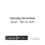
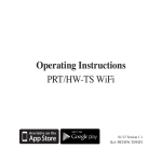
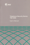
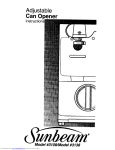
CMT1O3HR
IDE Controller and FlashDrive
Carrier utilityModule
User'sManual
HardwareRevision1.0
Publication
No. CMT103HR98.06.25
ISO9001 and AS9100 Certified
CMT1O3HR
IDE Controller and FlashDrive Carrier
utilityModule
I]ser's Manual
REAL TIME DEVICES USA,INC.
PO Box 906
200InnovationBlvd.
StateCollege,PA 16804-0906
USA
Phone:(814)234-8087
FAX: (8r4) 234-5218
E-Mail
[email protected]
techsupport@rtdusa.
com
Website
http://www.rtdusa.
com
Notice: We have attemptedto verify all information in this manual is correct as
of the publication date.Information in this manual may changewithout prior
notice from Real Time Devices USA.
Publishedby
RealTime DevicesUSA, Inc.
200InnovationBlvd.
P.O.Box 906
StateCollege,PA 16804-0906
USA
Copynght1998by RealTime DevicesUSA, Inc.
All rightsreserved
Printedin U.S.A.
PC/XT,PC/AT areregisteredtrademarksof IBM Corporation.
PCll}4 is a registeredtrademarkof PC/104Consortium.
TheRealTime DevicesLogo is a registeredtrademarkof RealTime Devices.
utilityModuleis a trademarkof RealTime Devices.
All othertrademarksappearingin this documentarethepropertyof their respectiveowners.
Tableof Contents
CHAPTER 1 INTRODUCTION
CHAPTER 2 CONFIGURINGTHE UTILITYMODTJLE..................
.........................3
CHAPTER 3 INSTALLING THE UTILITYMODULE
CHAPTER 4 COI\IYECTING THE UTILITYMODT]LE ......
PC/104Bus CorwscroRs,CNI aNnCN2
CHAPTER 5 USING THE UTILITYMODULE..................
..........................7
...................12
PowBnPnoTECTIoN
CIRC
CHAPTER 6 INTERT'ACING F'LASHDRTYES.....
..........16
THECMTIO3HRTo A COMPUTER
COTwECTNIC
WITHANIDE coNrnoLLER
ASTHEONLYIDE onrvn.................
I6
rHBCMTI03HR ro A coMpurERwrrHour ANIDE coNTRoLLER
Col.rNECTrNG
ASTHEoNLy IDE onrvs ..........16
Cor.rxBcrrNc
rse CMT103HRro e coMpurnRASTHEsEcoNDAny
naesrBn
IDE oruvscoNTRoLLER...............
l6
Usnce CMTI03HRASA sLAvEDRrvEoNA coMpurERwrrHAN
IDE coNrRoLLERANDAMesrsnnRrvs......lT
UsrNce CMTI03HR As A sLAVEDRrvEoN A coMpurERwrrHour ANIDE coNrnoLLERANDANoTHER
DRrvE
CMTI03HRAsA MASTER
..........
........17
CHAPTER 7 RETT]RNPOLICY AND WARRANTY...............
l8
IJser'sManual
1 INTRODUCTION
Ghapter
This manualgivesinformationon the CMT103HRIDE ControllerandFlashDisk
CarrierutilitvModule.This modulemounts1.8"ATA FlashDrivesin the PC|I}
stack.
CMT103HRIDE and FlashDrive Carrier utilitvModule
The CMTl03HR utilityModule was designedto provide a Flash drive in the
PC/104 stack to support the Real Time Devices cpuModules and other standard
PC/l 04 processormodules.
Features
The following aremajor featuresof the CMT103HRutilityModule.
Suppliedwith a SanDisk20 MB IndustrialgradeFlashDrive.
Allows up to four drivesin thePCllD4 stack. Supports1.8"Flashdrivessuchas
SanDisk
Jumperselectionofbus or cabledoperation
o Bus mode-- decodesIDE interfacethroughthe PC/104busfor
cablelessoperation
IDE mode-- attachesdrive to a cpuModulesIDE interfaceandto attacha slaveto
a masterdrive
Jumperselectionof primaryor secondary
IDE interfacein busmode
o Primary-- IDE Interfaceat 1F0-1F7h
o Secondary-- IDE Interfaceat 170-177h
Jumperselectionof masteror slavedrive
o
Master -- for the first drive on eachinterface
o
Slave - for the seconddrive on each interface
CMTI 03HRFlashDrive utilitvModule
Real Time DevicesUSA.Inc.
Features
Connectors
providedare:
Connectors
. CNl PCll}4 Bus (XT)
. CN2:PCllO Bus(AT)
. CN3:IDE cable
. CN4: 1.8"FlashDriveconnector
RecommendedCables
o TheCMT103HRrequiresa 40-pinIDE cableto connecta masterCMT103HR
to a slaveCMTI03HR or to connecta CMT103HRin IDE modeto a CPU
IDE adapter.
GeneralSpecifications
. Dimensions:3.8x 3.9x 0.6" (97x 100x 16mm)
. Weight(mass):3.0 ounces(85 grams)
. 4-layerPCB
'
3'#;ffi#:5Hfil'1#::tu*udrive)
.
.
relative humidity: 0 - 95oA,non-condensing
Storagetemperature: -55 to +125 degreesC
CMT 103HRFlashDrive utilitvModule
RealTimeDevicesUSA.Inc.
User'sManual
THE UTILITYMOOUUE
2 GoNFIGURING
Ghapter
The following sectionscontaininformationon configuringthe utilityModule.
Pleasereadthis entiresectionbeforeattemptingto usetheutilityModule!
Jumpers
Jumper JPl configuresthe following functions:
.
Master/Slave
.
Bus/Cabled
.
PimarylSecondary
Default Settings
The utilityModule is delivered from the factory configured according to the
following table.
Settine
l-2Ooen
l-2 Closed
3-4 Ooen
BUS
IDE
Function
MasterDrive
SlaveDrive
Reserved
DecodeIDE ThrouehPC/104bus
Use CN3 for IDE interface
If BUS mode is selectedthen:
PRI
Primarv IDE interface
SEC
SecondarvIDE interface
Notes:
1.Position3-4mustbe left open.
2. You mustselectonly oneof BUS or IDE.
3. If youhaveselected
BUS,you mustselectonly oneof PRI or SEC.
Jumper Locations
CMT I 03HR Flash Drive utilitvModule
RealTimeDevicesUSA"Inc.
Jumpers
The figure below showsjumper locations.
Jumper Locations
CMTI 03HRFlashDrive utilitvModule
RealTimeDevicesUSA.Inc.
Ijser'sManual
THE UTILITYMODULE
3 INSTALLING
Ghapter
Since the utilityModule usesa PCllD4 stackthroughbus, the only hardware
installation you will do is placing the module to the PCll}4 stack. To do this, you
will connectthe PC/l04 bus connectorwith the matching connectorof another
module.
Procedure
Recommended
We recommendyou follow the procedurebelow to ensurethat stacking of the
modules doesnot damageconnectorsor electronics.
o
Turn off power to the PCll}4 systemor stack.
o
Selectand install standoffsto properly position the utilityModule on the
PC/104stack.
o
Touch a groundedmetal part of the stack to dischargeany buildup of static
electricity.
o
Remove the utilityModule from its anti-staticbag.
o
Check that keying pins in the PC/I04 bus connectorare properly positioned.
o
Check the stacking order: make sure an XT bus card will not be placed
betweentwo AT bus cards,or it will intemrpt the AT bus signals.
o
Hold the utilityModule by its edgesand orient it so the bus connectorpins line
up with the matching connectoron the stack.
o
Gently and evenly pressthe utilityModule onto thePC/104 stack.
CAUTION: Do not force the module onto the stack! Wiggting the module
or applying too much force may damage it.If the module doesnot
readily press into place, remove it, check for bent pins or out-ofplace keying pins, and try again.
CMT 103HR Flash Drive utilitvModule
Real Time DevicesUSA.Inc.
RecommendedProcedure
4 GoNNECTINGTHE UTILITYMOOUIE
Ghapter
The following sectionsdescribeconnectorsof the utilityModule.
Finding Pin I of Connectors
The pin I end of connectorsis indicatedby a white areasilk-screenedon the PL
board. It is also indicated by a squaresolderpad visible on the bottom of the PC
board.
Pleasemake certain you have correctly identified pin 1 of a connectorbefore you
connectto it and attempt to use the utilityModule.
Connector Locations
The figure below shows connectorlocations.
[r'' o
M@^
**
Il*
,,i.ttttllt,-
'HrhmgWb
cMTIoJHR
'dfredb-
CN3
CNl
CN2
GonnectorLocations
Connectors
Connector
CNl
CN2
CN3
CN4
CMT 103HR Flash Drive utilityModule
Function
PCll}4 XT Bus
PC/104AT Bus
IDE Connector
2 mm Flash Drive Connector
Size
64pin
40 pin
40 oin
68 nin
Real Time Devices USA. Inc.
tjser's Manual
PC/104Bus Connectors,CNl and CN2
ConnectorsCNI and CN2 providePCll}4 bus connections.CNl carriesXT bus
signals,and CN2 carries additional signals for the AT bus. The signalson CNI
and CN2 conform to the IEEE P966 standardfor the PC/104 bus.
The following tables list the connectorpinouts:
Pin
PC/l04XT Bus Gonnector,GNI
RowA
Row B
I
2
3
4
5
6
7
8
9
t0
tl
12
13
I4
15
I6
17
t8
t9
20
2l
22
23
24
25
26
27
28
29
30
3l
32
CMT1 03HR Flash Drive utilitvModule
IOCHCHK*
SD7
SD6
SD5
SD4
SD3
SD2
SD1
SDO
IOCHRDY
AEN
SAI9
SAI8
SA17
SA16
SA15
SA14
SA13
SAI2
SA11
SAlO
SA9
SA8
SA7
SA6
SA5
SA4
SA3
SA.2
SAl
SAO
OV
OV
RESETDRV
+5V
TRO9
-5V
DRO2
-t2v
ENDXFR*
+l2Y
(KEYING PIN)
SMEMW*
SMEMR*
IOW*
IOR*
DACK3
DRO3
DACK1*
DROl
REFRESH
SYSCLK
IROT
IRO6
IRO5
IRO4
IRO3
DACK2*
TC
BALE
+5V
OSC
OV
OV
Real Time DevicesUSA.Inc.
PC/104Bus Connectors,CNl and CN2
PCl104AT Bus Gonnector.GN2
Pin
Row G
Row D
0
OV
SBHE*
LA23
LM2
L1.2I
LA2O
LAI9
LAl8
LAIT
MEMR*
MEMW*
SD8
SD9
SDlO
SDl1
SD12
SDI3
SDI4
SDI5
(KEYING PIN)
OV
MEMCSl6*
IOCSI6*
IROlO
IRO11
TROI2
IRO15
IROl4
DACKO*
DROO
DACK5*
DRO5
DACK6*
DRO6
DACKT*
DROT
+5V
MASTER*
OV
OV
I
2
a
J
4
5
6
7
8
9
10
11
t2
13
I4
15
t6
t7
18
19
Note:
Two locationson thebushavemechanicalkeyingpinsto help prevent
misconnection
of the PCllO4bus.Thesekeyingpins area part of the
PC/I04 standard,andwe stronglyrecommendyou leavethemin place.
If you haveothermoduleswithout keyingpins,we suggestyou modiS
themto includekeying.
CMT103HRFlashDriveutilitvModule
RealTimeDevicesUSA.Inc.
IJser's Manual
IDE, CN3
CN3 is a 40-pin 0.1" DIL connectoris the IDE input connectorin IDE mode and
the IDE output in BUS mode. The pinout of this connectoris shown below.
Pin
I
2
J
4
5
6
7
8
9
10
1l
t2
13
T4
15
16
l7
l8
19
20
2l
22
23
24
25
26
27
28
29
30
31
32
aa
JJ
34
35
36
IDE Hard Drive Connector.CN3
Function
Sienal
RESET*
GND
HD7
HD8
HD6
HD9
HD5
HDlO
HD4
HDIl
HD3
HDI2
HD2
HD13
HDI
ResetHD
Groundsienal
HD
HD
HD
HD
data 7
data 8
data 6
data 9
HD data5
HD data 10
HD data4
HD data 1l
HD data 3
HD datal2
IID data2
HD data13
HD data I
FID14
HDO
HD15
GND
HD data14
HD data 0
HD data15
Groundsienal
in/out
out
n/out
n/out
nlout
n/out
n/out
n/out
n/out
n/out
n/out
n/out
in/out
inlout
in/out
inlout
in/out
in/out
n.c.
AEN
GND
IOW*
GND
IOR*
GND
IOCHRDY
BALE
Address Enable
Ground signal
out
VO Write
Groundsimal
VO Read
Groundsisnal
out
out
VO ChannelReadv
1n
Bus AddressLatchEnable
out
n.c.
GND
Ground sienal
Intemrpt Request
IRQ
IOCSl6*
A1
GND
AO
A2
CMT103HRFlashDriveutilityModule
9
16bit transfer
AddressI
m
m
out
Ground signal
Address0
Address2
out
out
RealTimeDevicesUSA.Inc.
a-
)t
38
39
40
HCSO*
HCSl*
LED
GND
CMTI 03HRFlashDrive utilitvModule
HD Select0
HD SelectI
out
HDD activitvLED (-)
Groundsienal
m
out
RealTimeDevicesUSA.Inc.
IJser's Manual
Flash Drive, CN4
The 50 pin FlashDrive connectoris to connectharddrivesandFlashATA cards.
This workswith SanDiskFlashDrives.
CMT I 03HR Flash Drive utilitvModule
Real Time DevicesUSA.Inc.
Flash Drive. CN4
5 uslNc THE UTILITYMODULE
Ghapter
CMT I 03HR Flash Drive utilitvModule
Real Time DevicesUSA.Inc.
User'sManual
FlashHard Disk
In general,IBM-PC computerssupporttwo IDE interfaces.Eachinterfacecan
supporta masteranda slaveIDE drive which allowsup to 4 drivesin a computer
(assumingthatthe CPUBIOS supports4 drives).
The CMT103HRoperatesasa drive carrierto convertthe 50 pin 2 mm connector
on 1.8"Flashdrivesto the standard40 pin IDE connectorandprovidea
jumper.It canalsobe an IDE controllerfor computerswithout an
master/slave
IDE interfaceor to adda secondary
IDE interfaceto a computerthat only hasone.
Thesetwo modesof operationareselectedby installingoneof the IDE or BUS
jumpers.
Theharddrive controllerof the utilityModuleappearsasa standardPC IDE hard
drive controller.It will supportstandardIDE drives(lessthan528MB)and
enhanced
IDE drives(over528MB).
You may needto run the setupprogramfor your cpuModuleor computerto
configurethe correctharddrivetype.
IDE Mode
ThePC/104busonly providespowerto the drive. Theboardperformsa physical
interfacebetweenthe 50 pin 2 mm connectorandthe40 pin IDE connector.The
JP1pins 1-2jumpersselectmasteror slavemodefor the drive.
BUS Mode
This mode decodesthe PC/104 bus to createan IDE interface.This interface can
be the primary or secondaryinterface and the drive can be a masteror slave as per
the jumpers. The 40 pin IDE connectoris used to connect a seconddrive to this
interface. The seconddrive can be a standard3.5" drive or anotherCMT1O3HR or
CMT104 operatingin IDE mode.
CMT103HRFlashDriveutilitvModule
13
RealTimeDevicesUSA.Inc.
Flash Drive. CN4
PowerP rotection Circuitry
To reducetherisk of damagedueto power-supplyproblems,the utilityModule
includesseveralprotectivecomponents.
Module Power-SupplyProtection
The utilityModuleincludescomponents
to helppreventdamagedueto problems
with the +5Vdcpowersupplyfrom the PCll}4 busor power-supplyconnector.
Protectionis providedfor:
. Over-current
. Reversedpolarity
. Excessivevoltage
This protectionis only for theutilityModule,andwill not protectotherdevicesin
aPC/104stack.
Theprotectivefuseis replaceable
andis availablefrom electronicssuppliers.Its
descriptionandpartnumberare:
LittelfuseNanozSMF 1.0amp,R451-001
Caution:
Replacefusesonly with parts of identical current and voltage rating.
CMT1O3HR
FlashDriveutilitvModule
T4
Real Time DevicesUSA.Inc.
[.Jser'sManual
CMTI 03HR Flash Drive utilitvModule
15
Real Time DevicesUSA.Inc.
Connecting the CMTl03HR to a computer with an IDE controller as the only IDE drive
6 INTERFACING
FmSH DnlVeS
chapter
The utilityModule can be configured in severalmethods.
Connecting the CMT|03HR to a computer with an IDE
controller as the only IDE drive
.
.
.
.
.
.
.
InstallIDE jumper
RemoveBUSjumper
InstallPRIjumper(Not usedsincein IDE mode)
RemoveSECjumper(Not usedsincein IDE mode)
Connecta 40 pin cablefrom CPU'sIDE connectorto the CMTI03HR IDE connector
CN3, be carefulto observepin I orientation
RemovejumperJPI pins l-2 to selectmaster(pins3-4 shouldbe alwaysopen)
IJsethe CPU'ssetuputility to configuretheheads,cylindersandsectorsfor primary
masterdrive
Connectingthe CMT|03HRto a computerwithout an IDE
controller as the only IDE drive
.
.
.
.
.
.
InstallBUSjumper
RemoveIDE jumper
InstallPRIjumper
RemoveSECjumper
RemovejumperJPI pins l-2 to selectmaster(pins3-4 shouldbe alwaysopen)
IJsethe CPU'ssetuputility to configuretheheads,cylindersandsectorsfor primary
masterdrive
Connectingthe CMT|03HRto a computeras fhe secondary
masterIDE drive controller
.
.
.
.
.
.
InstallBUSjumper
RemoveIDE jumper
Install SECjumper
RemovePRIjumper
RemovejumperJPI pins l-2 to selectmaster(pins3-4 shouldbe alwaysopen)
IJsethe CPU'ssetuputility to configuretheheads,cylindersandsectorsfor secondary
masterdrive
CMT103HRFlashDriveutilityModule 16
Real Time DevicesUSA,Inc.
[.Jser'sManual
Using a CMT103HRas a slavedrive on a computer with an
IDE controller and a masterdrive
.
.
.
.
.
.
.
InstallIDE jumper
RemoveBUSjumper
InstallPRIjumper (Not usedsincein IDE mode)
RemoveSECjumper (Not usedsincein IDE mode)
Connecta threeconnector40 pin cablefrom CPU'sIDE connectorto themasterdrive
andto the CMT103HRIDE connectorCN3,be carefulto observepin I orientation
InstalljumperJPI pins l-2 to selectslave(pins3-4 shouldbe alwaysopen)
Usethe CPU'ssetuputility to configuretheheads,cylindersandsectorsfor the
primaryor secondaryslavedrive
Usinga CMT|03HRas a slavedrive on a computerwithout
an IDEcontrollerand anotherCMT|03HRas a masterdrive
Set the Master drive as abovethen set the slave as follows:
. Install IDE jumper
. Remove BUS jumper
. Install PRI jumper (Not used since in IDE mode)
. Remove SECjumper (Not used since in IDE mode)
. Install jumper JPl pins l-2 to selectslave (pins 3-4 should be always open)
. Connecta 40 pin cable from the masterCMT103HR IDE connectorCN3 to the
slaveCMTl03HR IDE connectorCN3, be careful to observepin 1 orientation
. IJse the CPU's setuputility to configure the heads,cylinders and sectorsfor primary
or secondarvslave drive
CMT103HRFlashDriveutilitvModule
17
RealTimeDevicesUSA.Inc.
Return Policv
z RETURN POLICY AND WInRANTY
Ghapter
ReturnPolicy
If the utilityModulerequiresrepair,you may returnit to us by following theprocedure
listedbelow;
Caution:
Failureto follow this returnprocedurewill almostalwaysdelayrepair!
Pleasehelp us expediteyour repair by following this procedure.
1) Read the limited warranty which follows.
2) Contact the factory and request a Returned Merchandise Authorization (RMA)
number.
3) On a sheetof paper, write the name, phone number, and fax number of a technicallycompetentperson who can answer questionsabout the problem.
4) On the paper, write a detailed description of the problem with the product. Answer the
following questions:
.
.
.
.
.
.
Did the product ever work in your application?
What other devices were connected to the product?
How was power supplied to the product?
What features did and did not work?
What was being done when the product failed?
What were environmental conditions when the product failed?
5) Indicate the method we should use to ship the product back to you.
. -Wewill return warranty repairs by UPS Ground at our expense.
. Warranty repairs may be refurned by a faster service at your expense.
. Non-warranty repairs will be returned by UPS Ground or the method you select,
and will be billed to you.
6) Clearly specifu the addressto which we should retum the product.
7) Enclose the paper with the product being returned.
8) Carefully packagethe product to be retumedusing anti-static packnging!We will not
be responsible for products damagedin transit for repair.
7) Write the RMA number on the outside of the package.
8) Ship the packageto:
Real Time Devices
200Innovation Blvd.
StateCollegePA 16803
USA
CMT103HRFlashDriveutilitvModule
18
RealTime DevicesUSA. Inc.
IJser'sManual
LimitedWarranty
RealTime Devices,Inc. warrantsthe hardwareandsoftwareproductsit manufactures
andproducesto be freefrom defectsin materialsandworkmanshipfor oneyear
following the dateof shipmentfrom REAL TIME DEVICES,USA. This warrantyis
limited to the originalpurchaserof productandis not transferable.
During the oneyearwalrantyperiod,REAL TIME DEVICESUSA will repairor
replace,at its option,any defectiveproductsor partsat no additionalcharge,provided
that the productis returned,shippingprepaid,to REAL TIME DEVICESUSA. All
replacedpartsandproductsbecomethepropertyof REAL TIME DEVICESUSA.
Before retuming any productfor repair, customersarerequiredto contactthe factory for
an RMAnumber.
THIS LIMITED WARRANTY DOESNOT EXTEND TO ANY PRODUCTSWHICH
HAVE BEEN DAMAGED AS A RESULTOF ACCIDENT,MISUSE,ABUSE (such
as:useof incorrectinput voltages,improperor insufficientventilation,failureto follow
the operatinginstructionsthat areprovidedby REAL TIME DEVICESUSA, "actsof
God" or othercontingencies
beyondthe controlof REAL TIME DEVICESUSA), OR
AS A RESULTOF SERVICEOR MODIFICATION BY AI{YONE OTHERTIIAN
REAL TIME DEVICESUSA. EXCEPTAS DGRESSLY SETFORTHABOVE, NO
OTI{ER WARRANTIESARE EXPRESSEDOR IMPLIED, INCLUDING, BUT NOT
LIMITED TO, ANY IMPLIED WARRANTIES OF MERCHANTABILITY AND
FITNESSFOR A PARTICULARPURPOSE,AND REAL TIME DEVICES
DGRESSLY DISCLAIMS ALL WARRANTIESNOT STATEDHEREIN.ALL
IMPLIED WARRANTIES, INCLUDING IMPLIED WARRANTIES FOR
MECHANTABILITY AND FITNESSFOR A PARTICULARPURPOSE,ARE
LIMITED TO THE DURATION OF THIS WARRANTY. IN THE EVENT THE
PRODUCTIS NOT FREEFROM DEFECTSAS WARRANTEDABOVE, THE
PURCHASER'SSOLEREMEDY SHALL BE REPAIROR REPLACEMENTAS
PROVIDEDABOVE. TINDERNOCIRCUMSTANCESWILL REAL TIME DEVICES
BE LIABLE TO THE PIJRCHASEROR ANY USERFORANY DAMAGES,
INCLUDING AIVY INCIDENTAL OR CONSEQUENTIALDAMAGES, EXPENSES,
LOST PROFITS,LOST SAVINGS,OR OTHERDAMAGES ARISING OUT OF THE
USE OR INABILITY TO USE TIIE PRODUCT.
SOMESTATESDO NOT ALLOW THE EXCLUSIONOR LIMITATION OF
INCIDENTAL OR CONSEQUENTIALDAMAGES FOR CONSUMERPRODUCTS,
AND SOME STATESDO NOT ALLOW LIMITATIONS ON HOW LONG AN
IMPLIED WARRANTY LASTS.SOTHE ABOVE LIMITATIONS OR EXCLUSIONS
MAY NOT APPLY TO YOU.
THIS WARRANTY GIVESYOU SPECIFICLEGAL RTGHTS,AND YOU MAY
ALSO HAVE OTHERRIGHTSWHICH VARY FROM STATETO STATE.
FlashDriveutilitvModule
CMT1O3HR
19
Real Time DevicesUSA.Inc.