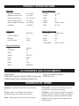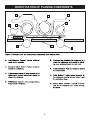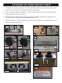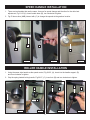
1
User Manual Read and understand this manual before using machine. 20” HEAVY DUTY PLANER Model Number 40285 40285H STEEL CITY TOOL WORKS VER. 9.13 TABLE OF CONTENTS HOW TO CONTROL THE FEED SPEED .......................13 USE OF THE ANTI-KICKBACK FINGERS .....................13 HOW TO ADJUST BELT TENSION ...............................13 HOW TO ADJUST BED ROLLERS ................................14 HOW TO ADJUST FEED ROLLERS ..............................14 HOW TO CHECK, ADJUST AND REPLACE KNIVES ...15 TABLE PARALLELISM ...................................................18 ADJUST INFEED/OUTFEED ROLLERS &PRESSURE BAR....20 ADJUST CHIPBREAKER/DEPTH SCALE.......................22 ADJUST TABLE GIBS ....................................................23 TROUBLESHOOTING GUIDE .......................................24 MAINTENANCE WITH SCHEDULES.............................26 IMPORTANT SAFETY & GUIDELINES .....................1 GENERAL SAFETY RULES ......................................2 ADDITIONAL SPECIFIC SAFETY RULES ................3 ELECTRICAL SAFETY PRECAUTIONS ...................3 FUNCTIONAL DESCRIPTION ..................................5 CARTON CONTENTS ...............................................5 UNPACKING AND CLEANING .................................6 PRODUCT SPECIFICATION ....................................7 IDENTIFICATION OF PLANING COMPONENTS.....8 ATTACHING HANDWHEEL ......................................9 ATTACHING TOP COVER AND DUST PARTS......10 SPEED HANDLE INSTALLATION...........................11 OPERATING CONTROLS AND ADJUSTMENTS ...12 IMPORTANT SAFETY INSTRUCTIONS WARNING: Read all warnings and operating instructions before using any tool or equipment. When using tools or equipment, basic safety precautions should always be followed to reduce the risk of personal injury. Improper operation, maintenance or modification of tools or equipment could result in serious injury and property damage. There are certain applications for which tools and equipment are designed. Steel City Tool Works strongly recommends that this product NOT be modified and/or used for any application other than for which it was designed. If you have any questions relative to its application DO NOT use the product until you have contacted Steel City Tool Works and we have advised you. Contact us online at www.steelcitytoolworks.com or call 877-724-8665. Information regarding the safe and proper operation of this tool is available from the following sources: ,QVWLWXWHPower Tool 1300 Sumner Avenue, Cleveland, OH 44115-2851 or online at www.powertoolinstitute.com 1DWLRQDO6DIHW\&RXQFLO1121 Spring Lake Drive, Itasca, IL 60143-3201 American National Standards Institute, 25 West 43rd Street, 4floor, NewYork, NY 10036 www.ansi.org - ANSI 01.1 Safety Requirements for Woodworking Machines 86'HSDUWPHQWRI/DERUUHJXODWLRQVZZZ.osha.gov SAVE THESE INSTRUCTIONS! SAFETY GUIDELINES - DEFINITIONS It is important for you to read and understand this manual. The information it contains relates to protecting YOUR SAFETY and PREVENTING PROBLEMS. The symbols below are used to help you recognize this information. DANGER: indicates an imminently hazardous situation which, if not avoided, will result in death or serious injury. WARNING: indicates a potentially hazardous situation which, if not avoided, could result in death or serious injury. CAUTION: indicates a potentially hazardous situation which, if not avoided, may result in minor or moderate injury. NOTICE: indicates a practice not related to personal injury which, if not avoided, may result in property damage. WARNING: Some dust created by power sanding, sawing, grinding, drilling, and other construction activities contains chemicals known to the State of California to cause cancer, birth defects or other reproductive harm. Some examples of these chemicals are: Lead from lead-based paints Crystalline silica from bricks and cement and other masonry products Arsenic and chromium from chemically-treated lumber (CCA). Your risk from these exposures varies, depending on how often you do this type of work. To reduce your exposure to these chemicals: work in a well-ventilated area, and work with approved safety equipment, such as those dust masks that are specially designed to filter out microscopic particles. 1 GENERAL SAFETY RULES WARNING: Failure to follow these rules may result in serious personal injury. 1. For your own safety, read the instruction manual before operating the machine. Learning the machine’s application, limitations, and specific hazards will greatly minimize the possibility of accidents and injury. 2. Wear eye and hearing protection and always use safety glasses. Everyday eyeglasses are not safety glasses. Use certified safety equipment. Eye protection equipment should comply with ANSI Z87.1 standards. Hearing equipment should comply with ANSI S3.19 standards. 3. Wear proper apparel. Do not wear loose clothing, gloves, neckties, rings, bracelets, or other jewelry which may get caught in moving parts. Nonslip protective footwear is recommended. Wear protective hair covering to contain long hair. 4. Do not use the machine in a dangerous environment. The use of power tools in damp or wet locations or in rain can cause shock or electrocution. Keep your work area well-lit to prevent tripping or placing arms, hands, and fingers in danger. 5. Do not operate electric tools near flammable liquids or in gaseous or explosive atmospheres. Motors and switches in these tools may spark and ignite fumes. 6. Maintain all tools and machines in peak condition. Keep tools sharp and clean for best and safest performance. Follow instructions for lubricating and changing accessories. Poorly maintained tools and machines can further damage the tool or machine and/or cause injury. 7. Check for damaged parts. Before using the machine, check for any damaged parts. Check for alignment of moving parts, binding of moving parts, breakage of parts, and any other conditions that may affect its operation. A guard or any other part that is damaged should be properly repaired or replaced with SCTW or factory authorized replacement parts. Damaged parts can cause further damage to the machine and/or injury. 8. Keep the work area clean. Cluttered areas and benches invite accidents. 9. Keep children and visitors away. Your shop is a potentially dangerous environment. Children and visitors can be injured. 10. Reduce the risk of unintentional starting. Make sure that the switch is in the “OFF” position before plugging in the power cord. In the event of a power failure, move the switch to the “OFF” position. An accidental start-up can cause injury. Do not touch the plug’s metal prongs when unplugging or plugging in the cord. 11. Use the guards. Check to see that all safety devices are in place, secured, and working correctly to prevent injury. 12. Remove adjusting keys and wrenches before starting the machine. Tools, scrap pieces, and other debris can be thrown at high speed, causing injury. 13. Use the right machine. Don’t force a machine or an attachment to do a job for which it was not designed. Damage to the machine and/or injury may result. 14. Use recommended accessories. The use of accessories and attachments not recommended by SCTW may cause damage to the machine or injury to the user. 2 15. Use the proper extension cord. Make sure your extension cord is in good condition. When using an extension cord, be sure to use one heavy enough to carry the current your product will draw. An undersized cord will cause a drop in line voltage, resulting in loss of power and overheating. See the Extension Cord Chart for the correct size depending on the cord length and nameplate ampere rating. If in doubt, use the next heavier gauge. The smaller the gauge number, the heavier the cord. 16. Secure the workpiece. Use clamps or a vise to hold the workpiece when practical. Loss of control of a workpiece can cause injury. 17. Feed the workpiece against the direction of the rotation of the blade, cutter, or abrasive surface. Feeding it from the other direction will cause the workpiece to be thrown out at high speed. 18. Don’t force the workpiece on the machine. Damage to the machine and/or injury may result. 19. Don’t overreach. Loss of balance can make you fall into a working machine, causing injury. 20. Never stand on the machine. Injury could occur if the tool tips, or if you accidentally contact the cutting tool. 21. Never leave the machine running unattended. Turn the power off. Don’t leave the machine until it comes to a complete stop. A child or visitor could be injured. 22. Turn the machine “OFF”, and disconnect the machine from the power source before installing or removing accessories, changing cutters, adjusting or changing set-ups. When making repairs, be sure to lock the start switch in the “OFF” position. An accidental start-up can cause injury. 23. Make your workshop childproof with padlocks, master switches, or by removing starter keys. The accidental start-up of a machine by a child or visitor could cause injury. 24. Stay alert, watch what you are doing, and use common sense. Do not use the machine when you are tired or under the influence of drugs, alcohol, or medication. A moment of inattention while operating power tools may result in injury. 25. WARNING: Use of this tool can generate and disperse dust or other airborne particles, including wood dust, crystalline silica dust and asbestos dust. Direct particles away from face and body. Always operate tool in well ventilated area and provide for proper dust removal. Use dust collection system wherever possible. Exposure to the dust may cause serious and permanent respiratory or other injury, including silicosis (a serious lung disease), cancer, and death. Avoid breathing the dust, and avoid prolonged contact with dust. Allowing dust to get into your mouth or eyes, or lay on your skin may promote absorption of harmful material. Always use properly fitting NIOSH/OSHA approved respiratory protection appropriate for the dust exposure, and wash exposed areas with soap and water. ADDITIONAL SPECIFIC SAFETY RULES WARNING: Failure to follow these rules may result in serious personal injury. 1. DO NOT OPERATE THIS MACHINE until it is completely assembled and installed according to the instructions. A machine incorrectly assembled can cause serious injury. 2. OBTAIN ADVICE f rom your supervisor, instructor, or another qualified person if you are not thoroughly familiar with the operation of this machine. Knowledge is safety. 3. 4. 5. FOLLOW ALL WIRING CODES and recommended electrical connections to prevent shock or electrocution. KEEP KNIVES SHARP and free from rust and pitch. Dull or rusted knives work harder and can cause kickback. NEVER TURN THE MACHINE “ON” before clearing the table of all objects (tools,scraps of wood,etc.). Flying debris can cause serious injury. 14. ALLOW THE CUTTERHEAD TO REACH FULL SPEED before feeding a workpiece. Changing speeds while planing can cause kickback. 15. WHEN PLANING BOWED STOCK place the concave (cupdown) side of the stock on the table and cut with the grain to prevent kickback. 16. DO NOT FEED A WORKPIECE that is warped contains , knots, or is embedded with foreign objects (nails, staples, etc.). Kickback can occur. 17. DO NOT FEED A SHORT, THIN, OR NARROW WORKPIECE INTO THE MACHINE. Your hands can be drawn into the knives and/or the workpiece can be thrown at high speeds. See the Operation section of this instruction manual for details. 18. DO NOT FEED A WORKPIECE into the outfeed end of the machine. The workpiece will be thrown out of the opposite side at high speeds. 6. NEVER TURN THE MACHINE “ON” with the work- piece contacting the cutterhead. Kickback can occur. 19. REMOVE SHAVINGS ONLY with the power “OFF” to prevent serious injury. 7. SECURE THE MACHINE TO A SUPPORTING SURFACE to prevent the machine from sliding, walking or tipping over. 20. PROPERLY SUPPORT LONG OR WIDE WORK-PIECES. Loss of control of the workpiece can cause serious injury. 8. PROPERLY SECURE THE KNIVES IN THE CUTTERHEAD before turning the power “ON”. Loose blades may be thrown out at high speeds causing serious injury. LOCK THE SPEED SETTING SECURELY before feeding the workpiece through the machine. Changing speeds while planing can cause kick-back. 21. NEVER PERFORM LAYOUT, ASSEMBLY or set-up work on the table/work area when the machine is running. Serious injury will result. 22. TURN THE MACHINE “OFF”, DISCONNECT IT FROM THE POWER SOURCE, and clean the table/work area before leaving the machine. LOCK THE SWITCH IN THE “OFF” POSITION to prevent un-authorized use. Someone else might accidentally start the machine and cause injury to themselves or others. 23. ADDITIONAL INFORMATION regarding the safe and proper operation of power tools (i.e. a safety video) is available from the Power Tool Institute, 1300 Sumner Avenue, Cleveland, OH 44115-2851 (www. powertoolinstitute.com). Information is also available from the National Safety Council, 1121 Spring Lake Drive, Itasca, IL 60143-3201. Please r efer to the American National Standards Institute ASNI 01.1 Safety Requirements for Woodworking Machines and the U.S. Department of Labor Regulations. 9. 10. AVOID AWKWARD OPERATIONS AND HAND POSITIONS. A sudden slip could cause a hand to move into the knives. 11. KEEP ARMS, HANDS, AND FINGERS away from the cutterhead, the chip exhaust opening, and the feed rollers to prevent severe cuts. 12. NEVER REACH INTO THE CUTTERHEAD AREA while the machine is running. Your hands can be drawn into the knives. 13. DO NOT STAND IN LINE OF THE WORKPIECE Kickback can cause injury. SAVE THESE INSTRUCTIONS Refer to them often and use them to instruct others. POWER CONNECTIONS A separate electrical circuit should be used for your machines. This circuit should not be less than #12 wire and should be protected with a time delay fuse. NOTE: Time delay fuses should be marked “D” in Canada and “T” in the US. If an extension cord is used, use only 3-wire extension cords which have 3-prong grounding type plugs and matching receptacle which will accept the machine’s plug. Before connecting the machine to the powerline, make sure the switch is(are) in the“OFF”position and be sure that the electric current is of the same characteristics as indicated on the machine. All line connections should make good contact. Running on low voltage will damage the machine. DANGER: Do not expose the machine to rain or operate the machine in damp locations. MOTOR SPECIFICATIONS Your machine is wired for 240 volt, 60 HZ alternating current. Before connecting the machine to the power source, make sure the switch is in the “OFF” position. 3 GROUNDING INSTRUCTIONS DANGER: This machine must be grounded while in use to protect the operator from electric shock. 1. All grounded, cord-connected machines: In the event of a malfunction or breakdown, grounding provides a path of least resistance for electric current to reduce the risk of electric shock. This machine is equipped with an electric cord having an equipment-grounding conductor and a grounding plug. The plug must be plugged into a matching outlet that is properly installed and grounded in accordance with all local codes and ordinances. Do not modify the plug provided - if it will not fit the outlet, have the proper outlet installed by a qualified electrician. Improper connection of the equipment-grounding conductor can result in risk of electric shock. The conductor with insulation having an outer surface that is green with or without yellow stripes is the equipment-grounding conductor. If repair or replacement of the electric cord or plug is necessary, do not connect the equipment-grounding conductor to a live terminal. Check with a qualified electrician or service personnel if the grounding instruction are not completely understood, or if in doubt as to whether the machine is properly grounded. Use only 3-wire extension cords that have 3-prong grounding type plugs and matching 3-conductor receptacles that accept the machine’s plug, as shown in Fig. A. NOTE: In Canada, the use of a temporary adapter is not permitted by the Canadian Electric Code. DANGER: In all cases, make certain that the receptacle in question is properly grounded. If you are not sure, have a qualified electrician check the receptacle. 2. Grounded, cord-connected machines intended for use on a supply circuit having a nominal rating between 150 - 250 volts, inclusive: GROUNDED OUTLET BOX Fig. A CURRENT CARRYING PRONGS If the machine is intended for use on a circuit that has an outlet that looks like the one illustrated in Fig. A, the machine will have a grounding plug that looks like the plug illustrated in Fig. A. Make sure the machine is connected to an outlet having the same configuration as the plug. No adapter is available or should be used with this machine. If the machine must be re-connected for use on a different type of electric circuit, the re-connection should be made by qualified service personnel; and after re-connection, the machine should comply with the National Electric Code and all local codes and ordinances. GROUNDING BLADE IS LONGEST OF THE 3 BLADES *NO PLUG OR CORD SUPPLIED MINIMUM GAUGE EXTENSION CORD RECOMMENDED SIZES FOR USE WITH STATIONARY ELECTRIC MACHINES EXTENSION CORDS Ampere Rating 0-6 0-6 0-6 0-6 6-10 6-10 6-10 6-10 10-12 10-12 10-12 10-12 12-16 12-16 12-16 WARNING: Use proper extension cords. Make sure your extension cord is in good condition and is a 3-wire extension cord which has a 3-prong grounding type plug and matching receptacle which will accept the machine’s plug. When using an extension cord, be sure to use one heavy enough to carry the current of the machine. An undersized cord will cause a drop in line voltage, resulting in loss of power and overheating. Fig. B shows the correct gauge to use depending on the cord length. If in doubt, use the next heavier gauge. The smaller the gauge number, the heavier the cord. Volts 240 240 240 240 240 240 240 240 240 240 240 240 240 240 240 Total Length of Cord in Feet up to 50 50-100 100-200 200-300 up to 50 50-100 100-200 200-300 up to 50 50-100 100-200 200-300 up to 50 50-100 GREATER THAN 50 FEET NOT RECOMMENDED Fig. B 4 Gauge of Extension Cord 18 AWG 16 AWG 16 AWG 14 AWG 18 AWG 16 AWG 14 AWG 12 AWG 16 AWG 16 AWG 14 AWG 12 AWG 14 AWG 12 AWG FUNCTIONAL DESCRIPTION FOREWORD The Model 40285 / 40285H is a 20" (508mm) Planer with an adjustable feed rate for optimum planing underload. This machine has cutting capacities of 20" (381mm) width, 6-1/2" (165mm) thick, and 1/8" (5mm) depth of cut. Feed rate is 16/20 FPM. NOTICE: The photo on the manual cover illustarates the current production model. All other illustrations contained in the manual are representative only and may not depict the actual labeling or accessories included. These are intended to illustrate technique only. CARTON CONTENTS Your new 20” (508mm) planer head shipped complete in one box. The machine is very heavy. Take care when you remove the machine. (See the section How To Lift The Machine). NOTICE: Some hardware/fasteners on the inventory list may arrive pre-installed on the machine. Check these locations before assuming that any items from the inventory list are missing. 10 9 4 7 8 18 5 3 12 17 6 2 11 1 16 19 14 15 1. 2. 3. 4. 5. Knife Setting Gauge Elevation Handwheel Lock Handle Open Endwrench (10mm and 12mm) Handwheel Handle 13 6. 7. 8. 9. 10. Shifting Handle (2) 2.5mm Hex Wrench 3mm Hex Wrench 4mm Hex Wrench 6mm Hex Wrench 11. 12. 13. 14. 15. 5 Dust Hood Dust Chute (2) Scale Cursor M5 x 10mm Bolt (6) 16. 17. 18. 19. M5 Washer (6) Knob Set Screw Handle UNPACKING AND CLEANING Carefully unpack the machine and all loose items from the shipping container(s). Remove the rust preventative oil from unpainted surfaces using a soft cloth moistened with mineral spirits, paint thinner or denatured alcohol. CAUTION: DO NOT use highly volatile solvents such as gasoline, naphtha, acetone or lacquer thinner for cleaning your machine. After cleaning, cover the unpainted surfaces with a good quality household floor past wax. CLEAN UP The unpainted surfaces are coated with a wazy oil to protect them from corrosion during shipment. Remove this protective coating with a solvent cleaner or citrus-based degreaser. To clean, some parts may need to be removed. For optimum performance from your machine, make sure you clean all moving parts or sliding contact surfaces that are coated. Avoid chlorine-based solvents, such as acetone or brake parts cleaner, as they may damage painted surfaces should they come in contact. Always follow the manufacturer’s instructions when using any type of cleaning product. These items are coated and must be cleaned: 1. Cutterhead 2. Feed Rollers 3. Table 4. Table Ways WARNING: Gasoline and petroleum products have low flash points and could cause an explosion or fire if used to clean machinery. DO NOT use gasoline or petroleum products to clean the machinery. WARNING: Many of the solvents commonly used to clean machinery can be toxic when inhaled or ingested. Lack of ventilation while using these solvents could cause serious personal health risks or fire. Take precautions from this hazard by only using cleaning solvents in a well ventilated area. 6 PRODUCT SPECIFICATIONS Capacities Product Dimensions Maximum stock width 20” / 508mm Footprint 42” x 30” Maximum stock thicknes 8” / 203mm Length 42” Maximum depth-of-cut 1/8” / 3.175mm Width 30” Minimum length of stock 8” / 203mm Height 49” Minimum length of thickness 1/8” / 203mm Weight 783lbs. / 355kg Feed Rate 16-20 FPM Table 20” x 30” Shipping Dimensions Cutterhead Speed 5000 RPM Carton Type Wooden Crate Number of Knives 3 Length 50.5” Diameter 2-7/8” Width 42.5” Cuts Per Minute 15,000 Height 31” Gross Weight 864lbs. / 392 kg Motor Specifications Type Induction Horsepower 5HP Amps 20 Voltage 220-240 V Phase Single Hertz 60 RPM’s 3450 Switch Mag Starter ACCESSORIES AND ATTACHMENTS 40923 Knives 40930 HSS Cutter Tips (Model 40285H 10 pack only) 40938 Carbide Cutter Tips (Model 40285H only) 40932 Torx Screws (25 pack) 40933 Torx Tool DEFINITION OF TERMS Workpiece – The wood or lumber that you are working on. Chatter Marks – An uneven “washboard” type of cut caused by incorrect chipbreaker settings. Planing – Refers to the sizing of the lumber to a desired thickness, while creating a level surface. Chip Marks – Occur when knives catch the chips and drag them across the lumber being planed, caused by exhaust blockage or improper chip deflector settings Snipe – Gouging that can occur at the end of a board. Tear Out – Deep gouging caused by improper chipbreaker settings. 7 IDENTIFICATION OF PLANING COMPONENTS 8 ATTACHING HANDWHEEL 1. To attach handwheel to elevation shaft Fig.8, remove nut and wash that were used to secure hand wheel shipping. Fig.10 (D). 2. Install knob Fig.7 onto the shaft and tighten to lock Fig.9. Fig.7 Fig.8 D Fig.9 Fig.10 9 ATTACHING TOP COVER AND DUST PARTS 1. To raise the lid, you need to attach the handle (B) Fig.10A with hardware (A) Fig.10A using Allen wrench. 2. Unlock lid, Fig.11 and Fig.12, turning knob (A) clockwise (both sides). 3. Lift lid and engage support bracket (B) Fig.13 / Fig.14 into recess (C) Fig.13 to prevent lid from closing. 4. Select hardware (E-F) Fig.16 (quantity 6). 5. Two people may be needed, one to hold cover, the other to install 6 bolts/washers into threaded cover. Fig.19 (I), Fig.18 (J), Fig.15 (D) as shown assemble Fig.17 (E-F). 6. Find two dust chutes, Fig.19 (G) using 8 screws (H) Fig.19 and Phillipps driver, attach the chute to cover. 7. Please note warning label Fig.20. B Fig.10A A Fig.16 Fig.17 F E F E TU R A Fig.11 J A N Fig.12 J B Fig.18 B C G Fig.13 Fig.14 H Fig.19 Fig.20 Fig.15 D 10 I SPEED HANDLE INSTALLATION 1. There are two handles that are the same. Use one for speed change and the other for the roller bed adjustment, Fig.21-22 (A). Insert handle base (B), turn clockwise to tighten. 2. Fig.23 shows how (A&B) interact with (C) to change the speeds at the gearbox location. A A B C Fig.21 Fig.22 Fig.23 ROLLER HANDLE INSTALLATION 1. Using the same style handle as the speed control, Fig.24-25, (A), insert into the handle support, (B) and turn clockwise to tighten. 2. Grip the spring loaded locking handle, Fig.26-27, (C), insert into (B) and turn clockwise to tighten. B B B B C C A A Fig.24 Fig.25 Fig.26 11 Fig.27 OPERATING CONTROLS AND ADJUSTMENTS HOW TO START AND STOP THE MACHINE 1. The on/off switch is located on the front of the planer. To turn the machine “ON”, push the START button (A) Fig.30. 2. To turn the machine “OFF”, push the STOP button (B) Fig.30. WARNING: Make sure that the switch is in the “OFF” position before plugging cord into outlet. DO NOT touch the plug’s metal prongs when unplugging or plugging in the cord. B A Fig.30 Fig.31 The location of the magnetic starter is behind the right side panel in the secured metal box, Fig.31 and shown open in Fig.32. To connect the planer to the power source, always use a licensed electrician. The connection point is at the rear of the planer and shown in Fig.33. Fig.32 Fig.33 12 HOW TO CONTROL THE FEED SPEED CAUTION: Change speeds only while the motor is running. DO NOT change speeds while planing. Your planer has two feed roll speeds: 16/20fpm and 8/10 per second. The slower feed rate provides more cuts per inch and a finer, smoother finish. For efficiency, operate the machine at the faster feed rate for general planing and switch to the slower feed rate for the final finish. When planing wide stock-wider than 8” (203) - particularly in hard wood, the slower feed speed is better because of less strain on the motor and a better finish. S When the shifter knob (S) 35 is moved up, down and center, you will have 20FPM (10cm/s), neutral and 16FPM (8cm/s) feed speeds. Fig.36 shows gearbox location behind panel. Shifters moves (T) on the gear box to change speeds. When the knob is in the neutral position, the machine will not feed. T Fig.35 Fig.36 USE OF THE ANTI-KICKBACK FINGERS WARNING: When inspecting and cleaning the anti-kickback fingers, disconnect the machine from the power source. A series of anti-kickback fingers (A) Fig.37 are provided on the infeed end of the planer. These anti-kickback fingers operate by gravity and no adjustment is required. However, you should inspect them occasionally to confirm that they are free of gum and pitch and that they move and operate correctly. A Fig.37 HOW TO ADJUST BELT TENSION WARNING: Disconnect the machine from the power source. 1. Remove side panels on left side of the planer as well as the panel on the front, under the bed to expose the belts and motor Fig.38-39. 2. By loosening the 4 nuts on the motor mount, (A-B), you will be able to rise or lower the motor as you need. 3. Belt tension, Fig.38 (C) should have a slight deflection of 1/4”. B C A Fig.38 13 Fig.39 HOW TO ADJUST BED ROLLERS 1. Bed rollers, Fig.40 (A) are set close to the table for finishing planing and higher for dimensioning rough stock. To adjust height see Fig.41. A C 2. Loosen nut (C) and turn bolt (B), you can raise or lower each of the 4 points of contact by repeating 4 times. This action moves (A). B A Fig.40 Fig.41 HOW TO ADJUST FEED ROLLERS Open both large side panels on each side of the machine to expose the end of the in/out feed rollers. Left side of machine is shown for clarity. Fig.42. By loosening nut (B) and moving bolt (A) and enlarged in Fig.43, you can raise or lower the height. Note: Rollers are set at factory and should need no adjustments. B B A A Fig.42 Fig.43 14 HOW TO CHECK, ADJUST, AND REPLACE KNIVES WARNING: Wear gloves when you remove the knives for sharpening or replacement. The knives in this planer are very sharp. WARNING: Disconnect the machine from the power source. 1. Fig.44, rotate knob (A) to unlock on both right and left side. Only left side shown. 2. Lift lid by handle, Fig.45 (B). Fig.46 shows lid open. 3. Engage (C) Fig.47 to prevent lid from closing. B OCK UNL Fig.45 A Fig.44 Fig.46 C Fig.47 15 SETTING/REPLACING KNIVES INSPECTING KNIVES Note: There are also springs in the cutterhead for adjustig knife height. Only one of these options is needed to set the knives—see Step 5 for clarification. Figure 12. Gauge positioned over cutterhead knife. Figure 13. Cutterhead profile diagram. 16 Springs—Push the knife down with the gauge so that the knife edge touches the middle pad of the gauge. Hold the gauge down and tighten the gib bolts just tight enough to hold the knife in place. Repeat Steps 5-7 with the rest of the knives. Note: If this is the first time you are setting the knives, remove the gib and knife from the cutterhead. The cutterhead comes with both springs and jack screws installed. Decide which adjustment option you are going to use. If you decide to use the jack screws, remove the springs from the cutterhead. If you decide to use the springs, you can just thread the jack screws completely into the cutterhead so they will not get lost. Replace the gib and knife. gure 12. Knife gauge. Figure ck Screws—Find the jack screws throu Jack through e access holes in the cutterhead (Figure (Figu the h 14)) and rotate the jack screws with a hex ench to raise or lower the knife. When the t wrench fe is set correctly, correctly it barely barel elly touches the t knife middle pad of the knife setting gauge. Snug the gib bolts tight enough to just hold the knife in place. Repeat Steps 5-7 with the rest of the knives. Figure 14. Jack screw access hole. 17 TABLE PARALLELISM How to Construct the Gauge Block Use a gauge block to check and adjust height of the chipbreaker and the infeed and outfeed roll. Adjust the cutterhead parallel to the table. Construct a gauge block from hard wood using the dimensions in Fig. 47. 3" (76.2mm) 1/2" (12.7mm) Fig. 47 2"(50mm) 4" (101.6mm) 1/4" (6.35mm) Table parallelism is critical to the operation of the planer. It is essential the table is parallel with the cutterhead within 0.003” from side-to-side, as illustrated in Figure 51. 4" (101.6 mm) (SEE NEXT PAGE FOR LARGER DIAGRAM) Figure 51. Side-to-side parallelism of table and cutterhead The easiest way to determine if your talbe has a parallelism problem is to plane a workpiece and measure the thickness in multiple locations. If the workpiece is tapered from left to right, then your table and cutterhead may not be parallel. Use your Rotacator to further inspect the tabpe parallelism. If you do not have a Rotacator, a wood block and feeler gauges may be used, but extra care must be taken to ensure accuracy if the table is not within the maximum allowable tolerance, it must be adjusted. 18 GRAIN DISCONNECT THE PLANER FROM POWER! Raise the headstock cover. (Refer to How to Check Knives page) Figure 53. Finding BDC with the Rotacator. Using the cutterhead pulley, rotate the cutterhead so taht the blade on the left edge of the cutterhead is at bottom dead center (BDC) (see Figure 52)—this will also place the knife on the right side of the cutterhead at BDC. elevation housing bracket cap screws ((A) underneath the table) for that side of the table (see Figure 54). the knife by slowly rocking the cutterhead pulley back and forth, and set the Rotacator dial to zero (see Figure 53). the knife just makes contact as it passes the feeler gauge. B A Figure 54. Table elevation screw housing bracket. Bottom Dead Center into the leverage hole and turn the bracket (B) until you are satisfied with the table parallelism from side-to-side. Figure 52. Cutterhead knife at bottom dead center (BDC). 19 ADJUST INFEED / OUTFEED ROLLERS & PRESSURE BAR 55 Figure 55. Infeed jam nut and bolt (left side shown). DISCONNECT THE PLANER FROM POWER! 56 + 57. Figure 56. Pressure bar jam nut and bolt (one side shown). 20 Figure 58. Wood blocks on planer table. Figure 57. Outfeed jam nuts and bolt (right side shown). 55 56 57 DISCONNECT THE PLANER FROM POWER! cutterhead with the knife at BDC (reference Distances Below Cutterhead at BDC at the beginning of these procedures). 58. gap between the edge of a knife at BDC and the wood blocks. 21 ADJUST CHIPBREAKER ADJUST DEPTH SCALE 58 DISCONNECT THE PLANER FROM POWER! Figure 57). Figure 58. Depth scale pointer. Figure 57. Chipbreaker mounting to headstock casting (right side shown.) 22 ADJUST TABLE GIBS Cap Screws 59 cap cap 3. Figure 59. Table gib and way. 23 TROUBLESHOOTING GUIDE This section covers the most common processing problems encountered in planing and what to do about them. Do not make any adjustments until planer is unplugged and moving parts have come to a complete stop. See the section on Wood Characteristics for additional troubleshooting information. PROBLEM LIKELY CAUSE(S) SOLUTION Motor will not start. 1. Low voltage. 1. Check power line for proper voltage. 2. Open circuit in motor or loose connections. 2. Inspect all lead connections on motor for loose or open connections. Motor will not start; fushes or circuit breakers blow. 1. Short circuit in line cord or plug. Motor overheats. 1. Motor overloaded. 1. Reduce load on motor. 2. Air circulation through the motor restricted. 2. Clean out motor to provide normal air circulation. Motor stalls (resulting in blown fuses or tripped circuit). 1. Short circuit in motor or loose connections. 1. Inspect connections on motor for loose or shorted terminals or worn insulation. 2. Low voltage. 2. Clean out motor to provide normal air circulation. 3. Incorrect fuses or circuit breakers in power 3. Install correct fuses or circuit breakers. line. 4. Motor overloaded. 4.Reduce load on motor. Machine slows when operating. 1. Feed rate too fast. 2. Depth of cut too great. 1. Change speed. 2. Reduce depth of cut. Loud, repetitious noise coming from machine. 1. Pulley setscrews or keys are missing or loose. 2. Motor fan is hitting the cover. 3. V-belt is defective. 1. Inspect keys and setscrews. Replace or tight if necessary. 2. Tighten fan or shim cover. 3. Replace V-belt. Machine is loud when cutting. Overheats or bogs down in the cut. 1. Excessive depth of cut. 2. Knives are dull. 1. Decrease depth of cut. 2. Sharpen knives. 1. Inspect cord or plug for damaged insulation and shorted wires. 2. Short circuit in motor or loose connections. 2. Inspect all connections on motor for loose or shorted terminals or worn insulation. 3. Incorrect fuses or circuit breakers in power 3. Install correct fuses or circuit breakers. line. Infeed roller marks are left on the workpiece. Depth of cut too shallow Increase depth of cut. Outfeed roller marks are left on right side of workpiece. Too much spring tension on feed roller. Refer to Feed Roller Pressure section for adjustment. Machine howls on startup. Chip deflector too close to the cutterhead. Move chip deflector back 1/8” to 1/4” from the cutterhead. Table moves down while cutting. 1. Replace knives. 2. Tighten table locking knobs. 1. Knives dull. 2. Table locking knobs are loose. 24 Excessive snipe (gouge in the end of the board that is uneven with the rest of the cute). Note: A small amount of snipe is inevitable with all types of planers. The key is minimizing it as much as possible. Workpiece stops/slows in the middle of the cut. 1. One or both of the table rollers are set too high. 2. Outfeed extension slopes down or is not level with the main table. 3. Chipbreaker or pressure bar set too low. 4. Workpiece is not supported as it leaves the planer. 1. Lower the table rollers. 1. Taking too heavy of a cut. 2. One or both of the bed rollers are set too low 3. Chipbreaker or pressure bar set too low. 4. Feed rollers set too low or too high. 1. Take a lighter cut. 2. Lower/raise the bed rollers. 5. Table not parallel with head casting. 6. Pitch and glue build up on planer components. Chipping (consistent pattern). 1. Knots or conflicting grain direction in wood. 2. Nicked or chipped carbide cutter. 2. Level the outfeed extension wings with the main table. 3. Raise the height of the chipbreaker or pressure bar. 4. Adjust and level the outfeed extension wing. 3. Raise the height of the chipbreaker or pressure bar. 4. Adjust the feed rolleres to the correct height. 5. Adjust the table so it is parallel to the head casting. 6. Clean the internal cutterhead components with a pitch/resin dissolving solvent. 5. Misadjusted chip breaker. 1. Inspect workpiece for nots and grain direction. 2. Rotate or replace the affected carbide insert. 3. Slow down the feed rate. 4. Take a smaller depth of cut. (Always reduece cutting depth when surface planing or working with hard woods.) 5. Adjust chipbreaker alignment and height. Fuzzy grain. 1. Wood may have high moisture content or surface wetness. 2. Dull cutters. 1. Check moisture content and allow to dry if moisture is too high. 2. Rotate/replace cutters. Long lines or ridges that run along the length of the board. 1. Nicked or chipped cutter(s). 1. Rotate/replace cutters. Uneven knife marks, wavy surface, or chatter marks across the face of the board. 1. Feeding workpiece too fast. 2. Misadjusted chipbreaker and/or pressure bar. 3. Worn cutterhead bearings. 1. Slow down the feed rate. 2. Adjust chipbreaker and/or pressure bar alignment, height, and tension. 3. Replace cutterhead bearings. Glossy surface. 1. Blades are dull. 2. Feed rate too slow. 3. Cutting depth too shallow. 1. Rotate/replace the blades. 2. Increase the feed rate. 3. Increase the depth of cut. Chip marks (inconsistent pattern). 1. Chips aren’t being properly expelled from the cutterhead. 1. Use a dust collection system rated for planer. 3. Feeding workpiece too fast. 4. Taking too deep of a cut. 25 MAINTENANCE WITH SCHEDULES SCHEDULE For optimum performance from your machine, follow this maintenance schedule and refer to any specific instructions given in this section. DAILY &ODQXQSDLQWHGFDVWLURQSDUWV &OHDQGXVWEXLOGXSIURPFXWWHUKHDGDQGIHHGUROOHUV WEEKLY ,QVSHFWDQGOXEULFDWHWKHHOHYDWLRQVFUHZV ,QVSHFWDQGOXEULFDWHWKHWDEOHZD\V ,QVSHFWDQGFOHDQIHHGUROOHUV MONTHLY CHECK. &OHDQYDFXXPGXVWEXLOGXSIURPEODGHVDQGRIIPRWRU ,QVSHFWDGMXVWUHSODFH9EHOWV /XEULFDWHDOOFKDLQV CLEANING 9DFXXPH[FHVVZRRGFKLSVDQGVDZGXVW:LSHRIIWKHUHPDLQLQJGXVWZLWKDGU\FORWK7KLVZLOOSUHYHQWWKHPRLVWXUHIURP ZRRGGXVWIURPUHPDLQLQJRQWKHEDUHPHWDOVXUIDFHV7UHDWDOOXQSDLQWHGFDVWLURQDQGVWHHOZLWKDQRQVWDLQLQJOXEULFDQW after cleaning. REPLACE V-BELTS &RUUHFW9EHOWGHIOHFWLRQLVó´ 7RROVQHHGHGDUHZUHQFKKH[ZUHQFKDQGSRVVLEO\DQRWKHUSHUVRQ 9EHOWUHPRYDODQGUHSODFHPHQWLVVLPSO\DPDWWHURIORRVHQLQJWKH9EHOWVUROOLQJWKHPRIIWKHSXOOH\VUHSODFLQJWKHP ZLWKQHZEHOWVWKHQUHWHQVLRQLQJWKHP7KLVSODQHUXVHV9EHOWVWRGULYHWKHFXWWHUKHDG$OZD\VUHSODFHZLWKD PDWFKHGVHWRWKHUZLVHXQHYHQEHOWWHQVLRQPD\FDXVHSUHPDWXUHEHOWIDLOXUH 7RUHSODFHGLVFRQQHFWIURPWKHSRZHUVRXUFHORRVHQWKHFDSVFUHZVDQGUHPRYHWKHSDQHOVRQOHIWVLGHDQGWKHIURQW. /RRVHQWKHQXWVRQWKHPRWRUPRXQWSODWHWRUHOHDVHWHQVLRQRQWKHEHOWV)LJ. Fig.60 :LWKDVVLVWDQFHOLIWWKHPRWRUXSDQGVOLGHDOOEHOWVRIIWKHPRWRUDQGFXWWHUKHDGSXOOH\V ,QVWDOOQHZEHOWVDQGUHYHUVHWKHSURFHGXUHV 26 Gearboxes Chains sses (found underneath the table and accessed Table Way Figure 10. Gearbox oil drawn/full locations Chain Tension 27 Table Chain Tension V-Belt Pulley Alignment DISCONNECT THE PLANER FROM POWER! DISCONNECT THE PLANER FROM POWER! Figure 28. Motor mounting fasteners for adjusting V-belt pulley alignment (bottom rear access panel removed). 28 Outfeed Roller Tension Infeed Roller Tension DISCONNECT THE PLANER FROM POWER! To adjust outfeed roller tension: DISCONNECT THE PLANER FROM POWER! 29 STEEL CITY TOOL WORKS www.steelcitytoolworks.com 1-877-SC4-TOOL (1-877-724-8665) NOTES www.steelcitytoolworks.com Steel City Tool Works, LLC Bolingbrook, IL. USA 60440 Tech Service: 1.877.724.8665