1
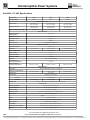
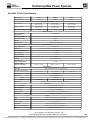
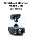
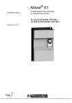
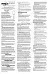
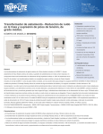
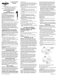
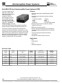
13
Uninterruptible Power Systems
Sola 2000 Off-Line Uninterruptible Power Systems (UPS)
The most complete off-line
UPS on the market, Sola
2000 UPS’s protect against
most adverse power
conditions. This UPS
protects against over and
under voltages by raising
and lowering utility power
to the right level for sensitive
equipment – all without
transfer to battery. Overload protection continually
monitors the UPS load preventing inadvertent shutdown
during emergency situations and optimizing battery life.
Full-sequence battery testing delivers comprehensive
testing of your battery and system, through both a 14-day
automatic test and a single-push manual test, ensuring the
battery is emergency ready. With its comprehensive power
protection, the Sola 2000 is perfect for PC, Point-of-Sale,
Network or Industrial applications. UL and cUL: 115 VAC
models. TÜV/GS and CE: 230 VAC models.
Features
• Off-line with Automatic Voltage Regulation (AVR)
topology.
• Protects against most adverse power conditions
including:
- Frequency variations
- Lightning
- Surge
- Spike
- Noise
- Brownouts
- Blackouts
- Over and under voltages
• Data-line surge protection for phone or network
included on every unit.
• DB9 Communications Interface.
• Greater uptime with intelligent power management,
full-sequence battery testing and two-level overload
protection.
• Two-year warranty with optional extensions
to five years.
• $25,000 UPS Power Protection Promise.
Applications
•
•
•
•
PCs
Workstations
PLCs
Computer peripherals
Selection Table
Capacity
(VA/W)
Catalog
Number
Volts, Frequency
In/Out
Typical
Runtime
(minutes)*
Input Plug/
Output Receptacle
Approx.
Ship Weight
lbs (kg)
350/210
S2350
115/115, 50/60 Hz
5/15
5-15P /(4) 5-15R
13.2 (6.0)
470/282
S2470
115/115, 50/60 Hz
5/12
5-15P / (4) 5-15R
15.4 (7.0)
700/420
S2700
115/115, 50/60 Hz
5/13
5-15P / (4) 5-15R
22 (10.0)
350/210
S2350-5
230/230, 50/60 Hz
5/15
EN60320/C14/ (4) EN60320/C13
13.2 (6.0)
470/282
S2470-5
230/230, 50/60 Hz
5/12
EN60320/C14/ (4) EN60320/C13
15.4 (7.0)
700/420
S2700-5
230/230, 50/60 Hz
5/13
EN60320/C14/ (4) EN60320/C13
22 (10.0)
*Full/Half load (in minutes).
156
Fax-on-Demand #: (877) 888-9329, Document #: 8371
Contact Technical Services at (800) 377-4384 with any questions.
Courtesy of Steven Engineering, Inc. ! 230 Ryan Way, South San Francisco, CA 94080-6370 ! Main Office: (650) 588-9200 ! Outside Local Area: (800) 258-9200 ! www.stevenengineering.com
13
Uninterruptible Power Systems
Power A/C Distribution (PAD) and Associate Receptacles/
Line Cord Options for the Series 2000
PADs provide output distribution receptacle, input
connection and a rotary maintenance bypass switch.
The PAD is field installable by the customer. Use of the
PAD allows the UPS to be removed without interrupting
power to the load.
Note: PADs can only be used with units having matching receptacles
for the line cords provided.
Description
Catalog
Number
120 Volt, 5-15P Line Cord/ (8) 5-15R
AD115A
120 Volt, 5-15P Line Cord/ (6) 5-15R, (2) L5-15R
AD115B
230 Volt 50 Hz, IEC 320-10A Line Cord,
(4) IEC 320-10 Receptacles
AD220K
Plug & Receptacle
Reference Chart
5-15P 5-15R IEC 320-10
Sola 2000 Battery Run Time Charts
S2350 and S2350-5 Models
S2470 and S2470-5 Models
S2700 and S2700-5 Models
Fax-on-Demand #: (877) 888-9329, Document #: 8371
Contact Technical Services at (800) 377-4384 with any questions.
157
Courtesy of Steven Engineering, Inc. ! 230 Ryan Way, South San Francisco, CA 94080-6370 ! Main Office: (650) 588-9200 ! Outside Local Area: (800) 258-9200 ! www.stevenengineering.com
13
Uninterruptible Power Systems
Sola 2000, 115 VAC Specifications
Catalog Number
S2350
Capacity (VA/Watts)
S2470
S2700
470/282
700/420
6.5 x 4.5 x 13.9
(166 x 115.5 x 352.5)
6.5 x 4.5 x 13.9
(166 x 115.5 x 352.5)
6.5 x 4.5 x 13.9
(166 x 115.5 x 352.5)
8.8 x 6.2 x 15.8
(226 x 156 x 404)
8.8 x 6.2 x 15.8
(226 x 156 x 404)
8.8 x 6.2 x 15.8
(226 x 156 x 404)
15.4 (7.0)
22.0 (10.0)
350/210
Dimensions - inches (mm)
Unit (H x W x D)
Shipping (H x W x D)
Approx. Shipping Weight - lbs(kg)
13.2 (6.0)
Input AC Parameters
Voltage Range without
Battery Operation
87 to 144 VAC
Line to Boost Transfer
104 VAC
Line to Buck Transfer
124 VAC
Frequency
50/60 Hz
Input Power Cord
6 ft. detachable, with NEMA 5-15P
Output AC Parameters
Voltage (Battery Mode)
Receptacles
115 VAC, ± 5%
5-15P / (4) 5-15R
5-15P / (4) 5-15R
Waveform (Battery Mode)
5-15P / (4) 5-15R
Stepped Sinewave
Voltage (Normal)
Vin x 1.0
Voltage (Boost Mode)
V in x 1.16
Voltage (Buck Mode)
V in x 0.84
Frequency
50 Hz or 60 Hz; auto sensing
Overload Warning
(Utility and Battery Modes)
Overload Shutdown
(Utility and Battery Modes)
101-120%
Overload + (15-30 W)
Overload + (20-40 W)
Overload + (30-60 W)
Battery Parameters
Battery Type
Sealed, Valve-Regulated Lead Acid, 3-5 years typical
Battery Qty x Voltage x Rating
(1) x 12 V x 7.0 AH
(1) x 12 V x 7 AH
Transfer Time
4-6 ms typical
Back-up Time:
See Battery Run Time Charts
Full Load
Half Load
Recharge Time
(1) x 12 V x 10 AH
> 5 minutes typical
> 15 minutes typical
> 12 minutes typical
> 13 minutes typical
7-10 hours to 90% capacity, after full discharge into 100% resistive load
Environmental
Operating Temperature
+32 oF to +104 oF (0 oC to +40 oC)
Storage Temperature
+5 oF to +122 oF (-15 oC to +50 oC)
Relative Humidity
Operating Elevation
0% to 90%, non-condensing
Up to 10,000 ft. (3000 m) at 95 oF (35 oC) without derating
Audible Noise
Less than 40 dB @ 1 meter
Agency
Safety
ESD
Surge Protection
IEC 801-2, Level 3, Criterion less than or equal to 2
Meets IEEE C62.41, Category A
Susceptibility
IEC 801-3, Level 3, Criterion less than or equal to 2
Electrical Fast Transient/Burst
IEC 801-4, Level 4, Criterion less than or equal to 2
Emissions
158
UL 1778, C-UL Listed
FCC Part 15, Subpart B, Class B
Fax-on-Demand #: (877) 888-9329, Document #: 8371
Contact Technical Services at (800) 377-4384 with any questions.
Courtesy of Steven Engineering, Inc. ! 230 Ryan Way, South San Francisco, CA 94080-6370 ! Main Office: (650) 588-9200 ! Outside Local Area: (800) 258-9200 ! www.stevenengineering.com
Uninterruptible Power Systems
13
Sola 2000, 230 VAC Specifications
Catalog Number
S2350-5
S2470-5
S2700-5
Capacity (VA/Watts)
350/210
470/282
700/420
6.5 x 4.5 x 13.9
(166 x 115.5 x 352.5)
6.5 x 4.5 x 13.9
(166 x 115.5 x 352.5)
6.5 x 4.5 x 13.9
(166 x 115.5 x 352.5)
8.8 x 6.2 x 15.8
(226 x 156 x 404)
8.8 x 6.2 x 15.8
(226 x 156 x 404)
8.8 x 6.2 x 15.8
(226 x 156 x 404)
15.4 (7.0)
22.0 (10.0)
Dimensions - inches (mm)
Unit (H x W x D)
Shipping (H x W x D)
Approx. Shipping Weight - lbs (kg)
13.2 (6.0)
Input AC Parameters
Voltage Range without
Battery Operation
166 to 275 VAC
Line to Boost Transfer
198 VAC
Line to Buck Transfer
250 VAC
Frequency
50/60 Hz
Input Power Cord
EN60320/C14 recessed plug
Output AC Parameters
Voltage (Battery Mode)
Receptacles
230 VAC, ± 5%
(4) EN60320/C13 sockets, (2) detachable EN60320-2-2 1.8m (6") power cords
Waveform (Battery Mode)
Stepped Sinewave
Voltage (Normal)
V in x 1.0
Voltage (Boost Mode)
Vin x 1.13
Voltage (Buck Mode)
Vin x 0.85
Frequency
50 Hz or 60 Hz; auto sensing
Overload Warning
(Utility and Battery Modes)
Overload Shutdown
(Utility and Battery Modes)
101-120%
Overload + (15-30 W)
Overload + (20-40 W)
Overload + (30-60 W)
Battery Parameters
Battery Type
Sealed, Valve-Regulated Lead Acid, 3-5 years typical
Battery Qty x Voltage x Rating
(1) x 12 V x 7.0 AH
(1) x 12 V x 7 AH
Transfer Time
4-6 ms typical
Back-up Time:
See Battery Run Time Charts
Full Load
Half Load
Recharge Time
(1) x 12 V x 10 AH
> 5 minutes typical
> 15 minutes typical
> 12 minutes typical
> 13 minutes typical
7-10 hours to 90% capacity, after full discharge into 100% resistive load
Environmental
Operating Temperature
+32 oF to +104 oF (0 oC to +40 oC)
Storage Temperature
+5 oF to +122 oF (-15 oC to +50 oC)
Relative Humidity
Operating Elevation
0% to 90%, non-condensing
Up to 10,000 ft. (3000 m) at 95 oF (35 oC) without derating
Audible Noise
Less than 40 dB @ 1 meter
Agency
Safety
EN50091-1, TUV/GS listed, CE Compliance Mark
ESD
IEC 801-2, Level 3, Criterion less than or equal to 2
Surge Protection
IEC 801-5, Level 3,
Susceptibility
IEC 801-3, Level 3, Criterion less than or equal to 2
Electrical Fast Transient/Burst
IEC 801-4, Level 4, Criterion less than or equal to 2
Emissions
EN50091-2, EN55011 Class B
Fax-on-Demand #: (877) 888-9329, Document #: 8371
Contact Technical Services at (800) 377-4384 with any questions.
159
Courtesy of Steven Engineering, Inc. ! 230 Ryan Way, South San Francisco, CA 94080-6370 ! Main Office: (650) 588-9200 ! Outside Local Area: (800) 258-9200 ! www.stevenengineering.com
Sola 2000
Guide Specifications
Fax-on-Demand # 8221
Uninterruptible Power Supply Systems - Sola 2000
Guide Specifications for a Sola2000 250 to 600 VA
Single - Phase Uninterruptible Power Supply System
1.0
GENERAL
1.1
SUMMARY
This specification defines the electrical and mechanical characteristics and requirements for a continuousduty single-phase, solid state, uninterruptible power supply system. The uninterruptible power supply system,
hereafter referred to as the UPS, shall provide continuous AC power for sensitive electronic equipment loads.
1.2
STANDARDS
The UPS shall be designed in accordance with the applicable sections of the current revision of the following
documents. Where a conflict arises between these documents and statements made herein, the statements
in this specification shall govern.
115V Units
•
•
•
•
•
UL Standard 1778
UL Standard 1449
FCC Part 15, Subpart B, Class B
IEEE 587, Category A and B
C-UL (CAN\CSA 22.2 No. 107.1)
230V Units
•
•
•
•
•
•
•
•
•
•
1.3
EN 50091-1
EN 55022, Class B
IEC 801-2
IEC 801-3
IEC 801-4
IEC 801-5
EN60950
EN50091-1
CE compliance mark
EMC Directive 89/336/EEC
SYSTEM DESCRIPTION
1
Fax-on-Demand: (877) 888-9329, Document #: 8221
Contact Technical Services at (800) 377-4384 with any questions.
Courtesy of Steven Engineering, Inc. ! 230 Ryan Way, South San Francisco, CA 94080-6370 ! Main Office: (650) 588-9200 ! Outside Local Area: (800) 258-9200 ! www.stevenengineering.com
1.3.1
Modes of Operation
The UPS shall be designed to operate as an off-line system in the following modes:
A. Normal - The critical AC load is continuously supplied with filtered power. The battery
charger shall maintain a float-charge on the battery.
B. Emergency - Upon failure of utility AC power, the critical AC load is supplied by the inverter
which obtains power from the battery.
C. Recharge - Upon restoration of utility AC power, after a utility AC power outage, the critical AC load
shall be supplied with filtered power and the battery charger shall simultaneously recharge the battery
automatically. The unit shall recharge whether the switch is in the on or off position (off state charging).
E. Dark Start - (400/600 VA only) The UPS shall have the ability to startup in the back-up mode without
the presence of utility power.
1.3.2
Design Requirements
A. Voltage: Input/Output voltage specifications of the UPS shall be:
Input:
115V units:
0 to 135 VAC, 50/60 Hz, single-phase, 2-wire-plus-ground.
230V units:
0 to 270 VAC, 50/60 Hz, single phase, 2-wire-plus-ground
Output:
115V units:
115 VAC, 50/60 Hz, single-phase, 2-wire-plus-ground.
230V units:
230 VAC, 50/60 Hz, single-phase, 2-wire-plus-ground
B. Output Load Capacity: Specified output load capacity of the UPS shall be:
• 250VA/150W
• 400VA/240W
• 600VA/360W
C. Internal Battery: The battery shall consist of sealed, valve regulated, reduced maintenance, lead acid cells.
The batteries shall be user-replaceable.
o
o
D. Reserve Time: Minimum 5 minutes at full load with ambient temperature between 20 and 30 C.
E. Battery Recharge: The recharge time shall be the following, to 90% capacity after discharge into a full load.
• 250VA
• 400/600VA
1.3.3
12-14hrs maximum
6-8hrs maximu
Performance Requirements
2
Fax-on-Demand: (877) 888-9329, Document #: 8221
Contact Technical Services at (800) 377-4384 with any questions.
Courtesy of Steven Engineering, Inc. ! 230 Ryan Way, South San Francisco, CA 94080-6370 ! Main Office: (650) 588-9200 ! Outside Local Area: (800) 258-9200 ! www.stevenengineering.com
1.3.3.1. AC Input to UPS
A. Voltage Configuration:
115VAC; +10%, -25% (90 to 135 VAC), single phase, 2-wire-plus-ground
230VAC; +15%, -22% (180 to 270 VAC), single phase, 2-wire-plus-ground
B. Frequency: 50 Hz or 60 Hz. UPS frequency is set via a DIP switch
C. Surge Protection: Sustains input surges without damage per criteria listed below:
115VAC - IEEE587, Category A & B; 240 Joules
230VAC - IEC 801-5 (Draft); 80 Joules
D. Input:
115 VAC units
All models shall have a 6 foot input power cord with a NEMA 5-15P plug.
230 VAC units
The input for all models shall be a CEE 22 recessed plug on the UPS. Specific country receptacles shall be
accommodated by using the computer’s input cord to feed the UPS.
1.3.3.2. AC Output, UPS Inverter (On Backup)
A. Voltage Configuration: 115VAC, single-phase-2-wire-plus-ground.
B. Voltage Regulation: +/- 5% for entire battery voltage range.
C. Frequency Regulation: +/- 2Hz
D. Output Power Rating: .6pf for all models
E. Overload Capability: 115% of power rating
F. Transient Recovery Response Time: 100% step load to within 90% of nominal output voltage within 500
milliseconds.
1.4
ENVIRONMENTAL CONDITIONS
A. Ambient Temperature
o
o
Operating: 0 C to +40 C
Storage:
o
o
-35 C to +50 C w/o battery
o
o
-20 C to 40 C for optimum battery performance
B. Relative Humidity
Operating: 0 to 95% non-condensing
Storage:
0 to 95% non-condensing
3
Fax-on-Demand: (877) 888-9329, Document #: 8221
Contact Technical Services at (800) 377-4384 with any questions.
Courtesy of Steven Engineering, Inc. ! 230 Ryan Way, South San Francisco, CA 94080-6370 ! Main Office: (650) 588-9200 ! Outside Local Area: (800) 258-9200 ! www.stevenengineering.com
C. Altitude
Operating: 3000 m (10,000 ft max.)
D. Audible Noise
Noise generated by the UPS during battery operation shall not exceed 40 dB measured at 1 meter from the
surface of the UPS.
1.5
USER DOCUMENTATION
The specified UPS shall be supplied with one (1) user’s manual. Manuals shall include installation drawings
and instructions, a functional description of the equipment with block diagrams, safety precautions,
illustrations, step by step operating procedures, and general maintenance guidelines. User manual for the
230V models shall be multi-lingual.
1.6
WARRANTY
The UPS manufacturer shall warrant the UPS against defects in materials and workmanship for two (2) years.
The warranty shall cover all parts and labor. An optional one (1) or three (3) year extended warranty shall be
available from the manufacturer.
1.7
QUALITY ASSURANCE
1.7.1
Manufacturer Qualifications
A minimum of twenty years experience in the design, manufacture, and testing of solid-state UPS systems is
required.
1.7.2
Factory Testing
Before shipment, the manufacturer shall fully and completely test the system to assure compliance with the
specification.
2.0
PRODUCT
2.1
FABRICATION
All materials and components making up the UPS shall be new, of current manufacture, and shall not have
been in prior service except as required during factory testing. All active electronic devices shall be solidstate. All relays shall be provided with dust covers.
2.1.1
Cabinet
The UPS unit shall be comprised of: battery charger, inverter, transfer switches, all associated controls,
monitoring, major protection devices and battery consisting of the appropriate number of sealed battery cells.
The UPS cabinet shall be cleaned, primed, and painted with the manufacturer's standard color. Dimensions
shall be:
250 VA
400 VA
600 VA
2.1.2
3.51” (90mm) W x 10.18” (261mm) D x 6.79” (174mm) H
4.25” (108mm) W x 10.18” (261mm) D x 7.02” (186mm) H
4.85” (124mm) W x 10.18” (261mm) D x 8.15” (215mm) H
Cooling
The UPS shall be convection cooled.
4
Fax-on-Demand: (877) 888-9329, Document #: 8221
Contact Technical Services at (800) 377-4384 with any questions.
Courtesy of Steven Engineering, Inc. ! 230 Ryan Way, South San Francisco, CA 94080-6370 ! Main Office: (650) 588-9200 ! Outside Local Area: (800) 258-9200 ! www.stevenengineering.com
2.2
COMPONENTS
2.2.1
Power Train
A. Input Protection
The UPS shall employ an input circuit breaker. The UPS shall sustain input surges without damage per
criteria listed in:
115VAC - IEEE587, Category A & B; 240 Joules
230VAC - IEC 801-5 (Draft); 80 Joules
B. Battery Recharge
The battery shall use constant voltage charging to recharge and maintain the battery.
C. Unit DC Protection
The unit shall be protected by the following DC shutdown levels:
• DC Undervoltage Shutdown (End of Discharge)
• DC Undervoltage Warning (Low Battery Reserve
D. Overload
The UPS shall be capable of supplying current and voltage for overloads exceeding 115% of full load current
for 30 minutes. A visual indicator and audible alarm shall indicate overload operation. The 400/600VA models
shall provide a visual indicator and audible alarm.
E. Output Frequency
The output frequency during normal operation shall follow the incoming AC frequency within a +/- 3Hz
window.
F. Battery Over Discharge Protection
To prevent battery damage from over discharging, the UPS control logic shall automatically raise the
shutdown voltage set point based on lighter loading.
2.2.2
Display and Controls
A. General
The UPS shall provide the operator with both visual and audible status indicators and shall indicate the
following conditions:
400 & 600 VA Units
•
•
•
•
•
•
•
•
•
Fail startup battery test
Input L-N reversed
Input frequency mismatch with DIP switch setting
Input line voltage below threshold
Output overload - short circuit
Normal Mode
Charger fail
Battery test fail
Input line overvoltage
5
Fax-on-Demand: (877) 888-9329, Document #: 8221
Contact Technical Services at (800) 377-4384 with any questions.
Courtesy of Steven Engineering, Inc. ! 230 Ryan Way, South San Francisco, CA 94080-6370 ! Main Office: (650) 588-9200 ! Outside Local Area: (800) 258-9200 ! www.stevenengineering.com
•
•
•
•
Output overload - short circuit
Low battery
UPS shutdown (end of discharge)
UPS shutdown via communication port
250 VA Units
•
•
•
•
•
•
•
•
•
•
•
Fail startup battery test
Input L-N reversed
Input frequency mismatch with DIP switch setting
Input line voltage below threshold
Output overload - short circuit
Normal Mode
Battery test fail
Input line over voltage
Output Overload - short circuit
Low Battery
UPS shutdown (end of discharge)
B. Controls
The UPS shall contain a front panel mounted main On/Off switch. The UPS shall also contain microcontrollerbased monitoring and controls for reliable operation.
C. DIP Switch Operation
The UPS shall contain four user-selectable DIP switches that will allow the following:
Switch 1
50/60Hz selection
Switch 2
Enable or Disable High Line Alarm
Switch 3
Transfer to Battery Setpoint
Switch 4
Enable/Disable line to neutral reversal alarm
D. Alarm Silence
On 400 and 600 VA models, the alarm silence switch shall be used to silence the On Battery alarm only,
whether utility power is present or not, except when operating in a low battery condition.
2.2.3
Automatic self diagnostic tests
The UPS shall perform three (3) different automatic self-diagnostic tests as described below:
A. Automatic self-diagnostic test: Power ON
The UPS must qualify the utility line voltage before initiating start-up. Qualification of the utility shall consist of
verifying utility power is within start-up voltage range.
Once the utility power has been qualified and followed by the UPS being switched ON, the UPS shall perform
start-up tests, consisting of an electronics and battery test, prior to enabling output power from the inverter.
Should the UPS fail any start-up test, the output power shall not be enabled and fault signals (visual and
audible) shall be enunciated.
6
Fax-on-Demand: (877) 888-9329, Document #: 8221
Contact Technical Services at (800) 377-4384 with any questions.
Courtesy of Steven Engineering, Inc. ! 230 Ryan Way, South San Francisco, CA 94080-6370 ! Main Office: (650) 588-9200 ! Outside Local Area: (800) 258-9200 ! www.stevenengineering.com
B. Automatic self-diagnostic test: Auto-restart
The UPS must qualify the utility line voltage before auto-restarting. Auto-restart shall be defined as the restart
of the UPS once utility power has returned (and qualified) after the UPS has shutdown due to battery
depletion.
Once the utility power has been qualified, the UPS shall perform auto-restart tests, consisting of an
electronics and battery test, prior to enabling output power from the unit. Should the UPS fail any test, the
output power shall not be enabled and fault signals (visual, audible, and remote via communications port)
shall be enunciated.
C. Automatic self-diagnostic test: Weekly
The UPS contains a counter which will initiate a battery test after seven days (168 hrs) of continuous normal
mode operation. The test duration shall be approximately 15 seconds. Should a failure of the battery occur,
the UPS will immediately return to normal mode and fault signals (visual, audible, and remote via
communications port) shall be enunciated. The seven day timer shall be reset after a manual battery test,
back-up mode operation or if the UPS is switched OFF. No audible or remote (via communications
port/contact closures) indication of the battery test shall be enunciated during the duration of the automatic
battery test.
2.2.4
Manual Battery Test (400 and 600 VA only)
The manual battery test switch on the back of the 400 & 600 VA units shall initiate a manual battery test only
when utility power is present and no alarm conditions are present. The test shall operate the same as the
automatic weekly test described in section 2.2.3 of this specification. Should the UPS batteries not be
capable of supporting the connected load for the test duration, the UPS shall immediately return to normal
operation, without loss of connected load and fault signals (visual, audible, and remote via communication
port) shall be enunciated. No audible or remote (via communication port/contact closures) indication of the
battery test shall be enunciated during the duration of the manual battery test.
2.2.5
Internal Battery
Sealed, valve-regulated, reduced-maintenance, lead acid cells shall be used as a stored-energy source for
the specified UPS system. The battery shall be housed internal to the UPS cabinet, and sized to support the
o
o
inverter at rated load and power factor, with ambient temperature between 20 and 30 C, for a minimum of 5
minutes reserve time. The batteries shall be user-replaceable.
2.2.6
Output Distribution
115 VAC units
Output distribution shall be integral to the UPS and located on the rear of the unit with the following
receptacles:
250VA
400VA
600VA
(2) NEMA 5-15
(4) NEMA 5-15
(4) NEMA 5-15
7
Fax-on-Demand: (877) 888-9329, Document #: 8221
Contact Technical Services at (800) 377-4384 with any questions.
Courtesy of Steven Engineering, Inc. ! 230 Ryan Way, South San Francisco, CA 94080-6370 ! Main Office: (650) 588-9200 ! Outside Local Area: (800) 258-9200 ! www.stevenengineering.com
230 VAC units
Output distribution shall be integral to the UPS and located on the rear of the unit with the following
receptacles:
250VA
400VA
600VA
(2) CEE-22
(4) CEE-22
(4) CEE-22
(2) cords shall be provided with each unit to connect the UPS output to the load.
2.2.7
Communications
The 400 and 600 VA models shall contain a DB25 connector on the rear panel to allow UPS status
communications to a computer system. The DB25 shall contain contact closures to signal on battery and low
battery operational status. The UPS shall also be capable of receiving a signal from the connected host
system to initiate a UPS shutdown. This signal shall be a + 5 V to +12 V (RS232 level) that must remain for >
0.1 second duration.
G:/techsvcspecs/info/cdrominfo/ups/guidespecs/2000GuideSpec.doc (8/99)
8
Fax-on-Demand: (877) 888-9329, Document #: 8221
Contact Technical Services at (800) 377-4384 with any questions.
Courtesy of Steven Engineering, Inc. ! 230 Ryan Way, South San Francisco, CA 94080-6370 ! Main Office: (650) 588-9200 ! Outside Local Area: (800) 258-9200 ! www.stevenengineering.com