1
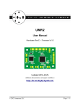
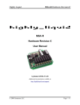
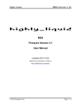
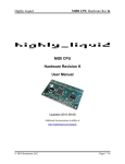
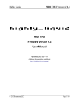
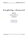
Highly Liquid
MSA-R Hardware Revision K
MSA-R
Hardware Revision K
User Manual
Updated 2010-11-01
Additional documentation available at:
http://highlyliquid.com/support/
© 2010 Sonarcana LLC
Page 1 / 8
Highly Liquid
MSA-R Hardware Revision K
Table of Contents
1.0 Important Safety Information...................................................................................................2
2.0 Feature Diagram........................................................................................................................2
3.0 Mechanical Drawing.................................................................................................................3
4.0 Power Supply............................................................................................................................4
5.0 MIDI Wiring.............................................................................................................................5
6.0 Program Switch and Remote Activity LED..............................................................................7
7.0 Outputs......................................................................................................................................8
7.1 Electrical Specifications.......................................................................................................8
7.2 Equivalent Schematic...........................................................................................................8
8.0 Component Lead Identification & Mounting...........................................................................8
1.0 Important Safety Information
To prevent damage to the MSA-R and connected devices, and to prevent personal injury:
●
Take reasonable static-control precautions when handling the MSA-R. This product includes
ESD-sensitive parts.
●
Use an appropriate power source.
●
Do not exceed the electrical specifications of the MSA-R relay outputs.
2.0 Feature Diagram
© 2010 Sonarcana LLC
Page 2 / 8
Highly Liquid
MSA-R Hardware Revision K
3.0 Mechanical Drawing
© 2010 Sonarcana LLC
Page 3 / 8
Highly Liquid
MSA-R Hardware Revision K
4.0 Power Supply
To operate, the MSA-R must be connected to a battery or other DC power supply. A “wall adapter”
supply with appropriate specifications may be used.
Power supply requirements:
●
Output voltage: 9VDC
●
Current capacity (no load on Regulated 5V Output): 200mA or greater
●
Current capacity (loaded Regulated 5V Output): Varies with 5V load current
Wire the battery or power supply to the MSA-R “POWER IN” terminals as shown in Figure 4.1.
The Regulated 5V Output (“POWER REG” terminals) can supply up 100mA of output current. Do not
attach a power supply to the “POWER REG” terminals of the MSA-R.
Figure 4.1: Power Supply Wiring
© 2010 Sonarcana LLC
Page 4 / 8
Highly Liquid
MSA-R Hardware Revision K
5.0 MIDI Wiring
The MSA-R features MIDI IN, OUT and THRU ports. Wire MIDI receptacles as shown in Figure 5.1.
Pin 2 is wired only at the OUT or THRU side of the MIDI link. Pins 1 & 3 are unused.
Use the MIDI IN and MIDI THRU ports as shown in Figure 5.2.
If chaining multiple MSA units, MIDI connectors can be eliminated. See Figure 5.3.
The MIDI OUT port can be used to retrieve the MSA-R configuration via MIDI SysEx message. See
MSA Firmware User Manual.
Figure 5.1: MIDI Receptacle Wiring
© 2010 Sonarcana LLC
Page 5 / 8
Highly Liquid
MSA-R Hardware Revision K
Figure 5.2: MIDI IN/THRU
Figure 5.3: Multiple-Device Chain
© 2010 Sonarcana LLC
Page 6 / 8
Highly Liquid
MSA-R Hardware Revision K
6.0 Program Switch and Remote Activity LED
A user-supplied “program” switch and remote activity LED can be attached as shown in Figure 6.1.
The program switch activates “learn mode” and other programming features of the MSA-R. Use a
normally-open momentary switch. See MSA Firmware User Manual for additional details.
Figure 6.1: Program Switch and Remote Activity LED Wiring
© 2010 Sonarcana LLC
Page 7 / 8
Highly Liquid
MSA-R Hardware Revision K
7.0 Outputs
7.1 Electrical Specifications
●
Maximum Switching Voltage: 24VAC
●
Maximum Switching Current: 500mA
●
Typical "On" Resistance: 0.2Ω
●
Approximate Switching Delay: 1ms
7.2 Equivalent Schematic
Each MSA-R output is a reed relay which acts as an SPST switch. See Figure 7.1.
Use each output terminal pair as you would use the terminals of an SPST switch.
Figure 7.1: Output Equivalent Schematic
8.0 Component Lead Identification & Mounting
If mounting relays and output indicator LEDs, place components as shown below.
© 2010 Sonarcana LLC
Page 8 / 8