1
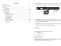
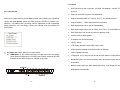
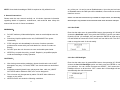
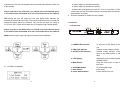
DIAPro ArtNet to DMX 44 Technical Specification Power Supply .................…………………AC100-240V, 50/60Hz Dimensions.....................……………...…482x155x44mm Weight.....................……………...…........2.3kgs Innovation, Quality, Performance User Guide Please read these instructions carefully before use 15C CONTENTS 1. Features ....................................................................................................... 2 2. General Instructions ..................................................................................... 3 3. Overview ...................................................................................................... 4 3.1 Front View ........................................................................................... 4 3.2 Rear View ........................................................................................... 5 4. Operation Guide ........................................................................................... 5 4.1 Startup View ........................................................................................ 5 4.2 Main Menu .......................................................................................... 7 4.2.1 Rename Device .......................................................................... 8 4.2.2 Set IP Address . .......................................................................... 8 4.2.3 Set Netmast ................................................................................ 8 4.2.4 Set DMX Port .............................................................................. 9 4.2.5 Set ID NO. .............................................................................. 12 4.2.6 Set LCD Backlight…………… ……..…………………….… .…...12 4.2.7 User Preset............................................................................... 13 4.2.8 Version…………………………………………………………...….14 2) ArtNet Clone: Direct through mode, the preset is used to replicate a standard ArtNet signal from 2 (1-2) Input ports to 2(3-4) output ports. 3) Isolated Mode: It will isolate the DMX input and output. The DMX input wouldn’t output the DMX signal to the DMX out port. They will receive the signal from the network individually. 4) Factory Setting: All of the setting including the device name, device ID as well as device IP will be restored to the original status. 4.2.8 Version You can check the version number from this option. Application Diagram Please Note that: The unit cannot be circular connected, or it will cause cyber storm to affect the performance of system. 1C 14C 1. Features RJ45 Ethernet (LAN) connector, 10/100M self-adaption, support TCP/IP protocol 4.2.7 User Preset Enter into the main menu by press MENU button, then pressing UP / DOWN to choose the User Preset option and then press the ENTER to confirm your selection. This setting help you easily use the application avoid complicated setup procedure. You can simply choose you desired mode by pressing UP and DOWN. 1) 4 x Input: Make the 4 DMX port as Input status. a) DMX Split 1-3: This setting will help you make the unit as one splitter which with one DMX input to 3 DMX output. Please note that the LED indicator of the DMX Output port will light up in green. Ethernet connector supports Auto MDI/MDIX Support standard DMX-512, sACN(E1.31)and ArtNet protocol Support ArtNet←→DMX signal bilateral conversion DMX input/output can be set as able/disabled Each DMX output can be set as single, zero, HTP, LTP and RDM mode Each DMX input can be set as normal or backup mode Can be acted as DMX splitter IP address can be set manually Factory setting LCD display indicates each DMX output status LED indicators indicate the activate status of Ethernet Online updates software 4 DMX port , any of the port can be set as input status or output status Broadcast mode, one device transmits while all devices receive the same information Backup mode, when one DMX signal goes faulty, it will output the other DMX signal automatically. 13C 2C NOTE: Some basic knowledge of DMX is required to fully utilize this unit. Any of the port 1-4 can be set as Disabled status. Upon the port has been set as Disabled status, the DMX port will be disabled, it cannot send or receive any data from now on. 2. General Instructions Please read the user manual carefully, as it includes important information regarding details of operation, maintenance, and technical data. Keep this manual with the unit for future consultation. Please note that the Framerte/fs only available for Output status; The Secondly and Resend option only available for the HTP/LTP mode under the status of Output. 4.2.5 Set ID NO. WARNINGS! Enter into the main menu by press MENU button, then pressing UP / DOWN to DO NOT make any inflammable liquids, water or metal objects enter the unit. Should any liquid be spilled on the unit, DISCONNECT the power immediately. STOP using the unit immediately in the event of serious operation problems and contact with your local dealer for a check or contact us directly. DO NOT open the unit--there are no user serviceable parts inside. NEVER try to repair the unit by yourself. Repairs by unqualified people could cause damage or faulty operation. choose the Set ID NO. option, then press the ENTER to confirm your selection. Press the ID No. (for example: 001) and press the ENTER to enter and press UP and DOWN to choose the ID No. for the unit from 000 to 255. The ID is only used to recognize each of the unit easily. 4.2.6 Set LCD Backlight CAUTIONS! After having removed the packaging, please check that the unit is NOT damaged in any way. If in doubt, DON'T use it and contact an authorized dealer. Packaging material (plastic bags, polystyrene foam, nails, etc.) MUST NOT be left within children's reach, as it can be dangerous. This unit must only be operated by adults. DO NOT allow children to tamper or play with it. NEVER use the unit under the following conditions: 3C Enter into the main menu by press MENU button, then pressing UP / DOWN to choose the Set LCD Backlight option and then press the ENTER to confirm your selection. You can choose its status as ON/OFF. “ON” means the LCD backlight will turn on all the time. “OFF” means the LCD backlight will turn off automatically after idle 30 seconds. 12C and secondly. The unit will compare the two universal and resend the later one to the network. In places subject to excessive humidity. In places subject to vibrations or bumps. In places with a temperature of over 45℃/113 F or less than 2℃/35.6 F. Protect the unit from excessive dryness or humidity (ideal conditions are between35% and 80%). Please note that in the LTP mode, you should ensure the Resend option is not at the status of Disabled. Or it won’t resend the data to the network. HTP means the port will output the one with higher value between the universal of principle and secondly. The unit will compare the two universal and resend the higher data to the network. They can be set within the range of 0.0-F.F./001-255. (These two formats can be change through Display Mode) DO NOT dismantle or modify the unit privately. 3. Overview 3.1 Front View Please note that in the HTP mode, you should ensure the Resend option is not at the status of Disabled. Or it won’t resend the data to the network. RDM means the port output can support Remote Device Manager. To show the on/off status of the unit Network connect status indicate Network activity indicator, when there is any data transmit, it will flash. display the present status and the available option Enter into main menu or back to last menu UP and DOWN button Enter button Power ON/OFF the unit 1 POWER LED indicator 2 LINK LED indicator 3 ACTIVITY LED indicator 4 LCD Display 5 Menu Button 3) 1-4 DMX port disabled 6 UP/DOWN Button 7 Enter Button 8 Power Switch Button 11C 4C Backup mode refers that when there is any data on the universal of network, the CA-AN04 won’t send any data to universal of network. Only when the universal of network is no any data, then the CA-AN04 will receive the data from DMX IN port and send it to the universal of network simultaneously. 3.2 Rear View 2) 1-4 DMX output 9 Connect with the power cord Power supply 10 Ethernet RJ45 connector Connect with network cable 11 DMX port 1-4 Can be set as DMX in/DMX out 4. Operation Guide Nowadays many occasions require thousands of DMX channels. And with the increased use of LED fixtures and video mapping, it is now necessary to have fast DMX response and proper network load management. CA-AN44 can realize not only instant response but also lower network load. It allows users to increase the number of DMX universes and easily place DMX universes remotely on any TCP/IP Ethernet network. In addition, the CA-AN44 can be used as a DMX merger, DMX splitter, backup device and so on. Any of the port 1-4 also can be set as Output status. Upon the port has been set as Output status, there are LTP, HTP, zero, single and RDM these 5 modes can be selected. 4.1 Startup View Zero means the port output should be “0’; Single means this port will only output one universal. LTP means this port will output the latter one between the universal of principle 5C 10C 4.2.4 Set DMX port Enter into the main menu by press MENU button, then pressing UP / DOWN to choose the DMX port option and then press the ENTER to confirm your selection. Then you can set the parameter of the each port by pressing the ENTER and UP/DOWN. There are 4 different statuses (as pictures show) you can check when you power on your unit. You can switchover them by pressing the UP/DOWN button. All of the options can be changed in the main menu. In the port status, A/B means the network port; “x” means there is no network connected. “√” means the network has been connected. 1-4 refers to the DMX port 1-4. In the status, “x” means the DMX port’s status is inactive. It will hold the current output. “√” stands the DMX port’s status is activity, it has connected to the network. “o” means the current port status is set to DMX output; “I” means the DMX ports is set to DMX input status. 1) 1-4 DMX Input You can set any of the DMX port 1-4 as Input status. Then only the principle universal is available. It can be set within the range 0.0 - F.F. As the DMX port has been set as Input status, then the Mode only can be set as normal or backup. Normal mode means it will send the data received from DMX IN port to the universal of network regardless if there is any data in the universal of the network. 9C 6C 4.2 Main menu 4.2.2 Set IP Address Enter into the main menu by press MENU button, then pressing UP / DOWN to choose the Set IP Address option and then press the ENTER to confirm your selection. Now you can set IP address by pressing UP and DOWN now. Confirm you change and move to next option by press the ENTER and UP/DOWN. Please note: Each of the IP address should be unique. 4.2.3 Set Netmask Enter into the main menu by press MENU button, then pressing UP / DOWN 4.2.1 Rename Device Enter into the main menu by press UP/DOWN button, then pressing the to choose the Netmask option and then press the ENTER to confirm your selection. Now you can set Netmask by pressing UP and DOWN now. Confirm you change and move to next option by pressing the ENTER and UP/DOWN. button to choose the Rename Device option and then press the ENTER button to confirm your selection. Now you can rename the device by pressing UP and DOWN now. Confirm you change and move to next option by press the ENTER. 7C 8C