1
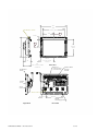
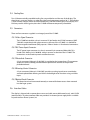
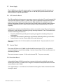
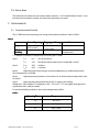
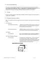
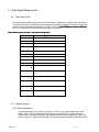
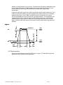
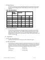
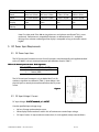
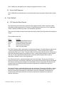
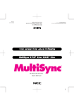
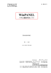
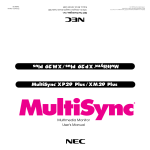
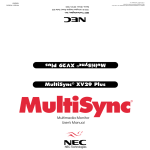
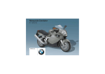
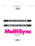
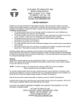
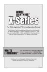
LC1200R High-Bright Monitor USER’S MANUAL www.planar.com TABLE OF CONTENTS 1 INTRODUCTION 4 2 BASIC CONSTRUCTION 4 2.1 LCD Display 4 2.2 Weight 5 2.3 Mechanical 5 2.4 Cooling Fans 7 2.5 Connectors 7 2.6 Interface Cables 7 2.7 Power Supply 8 2.8 LCD Controller Board 8 2.9 Inverter Board 8 2.10 Photodiode Board 8 2.11 Button Board 9 3 ENVIRONMENTAL 9 3.1 Temperature and Humidity 3.2 Direct Sunlight Operation 10 3.3 Altitude 10 3.4 Mechanical Vibration and Shock 10 4 9 VIDEO SIGNAL REQUIREMENTS 11 4.1 Video Input Lines 11 4.2 Signal Functions 11 4.3 Signal Quality 14 4.4 Timing and Frequency 15 4.5 Video Signal On-Off Sequences 15 5 DC POWER INPUT REQUIREMENTS 16 5.1 DC Power Input Lines 16 5.2 DC Input Voltage / Current 16 5.3 Power On-Off Sequences 17 6 USER CONTROLS 17 6.1 LCD Controller Board Controls 17 6.2 User Adjustments 18 6.3 Dimming 20 7 MONITOR PERFORMANCE 22 7.1 Monitor Luminance 22 7.2 Display Contrast 22 LC1200R User’s Guide 021-0183-00 Rev A 2 of 29 7.3 Display Uniformity 23 7.4 Display Chromaticity 23 8 DISPLAY COSMETICS 24 8.1 Black Display Picture Mode 24 8.2 White Display Picture Mode 24 9 REGULATORY AGENCY REQUIREMENTS 24 9.1 Safety Certification 24 9.2 CE Marketing 24 9.3 RFI Emission Certification 25 9.4 System Transient Disturbance Requirements 25 9.5 Labeling 25 9.6 ROHS Compliance 26 10 RELIABILITY 26 10.1 Design Workload 26 10.2 MTBF 26 11 DESCRIPTION OF WARRANTY 26 12 SUPPORT AND SERVICE 27 13 GLOSSARY OF TERMS 28 LC1200R User’s Guide 021-0183-00 Rev A 3 of 29 1 Introduction This document defines the electromechanical parameters and operating characteristics for The Planar Systems, Inc. LC1200R, Very High Bright, 12.1” Active Matrix Liquid Crystal Display (AMLCD) based product. It is intended for operation as a component in a high ambient light, outdoor system. The LC1200R has a scaleable video format capable of displaying a minimum of VGA (640 x 480) through XGA (1024 x 768) input resolution. The LC1200R can be driven directly from the standard analog video graphics adapter (VGA) output on a personal computer (PC). It consists of a 12.1" viewable diagonal LCD panel with optical elements, cold-cathode fluorescent backlight, backlight inverter board, and LCD controller board. A tethered photodiode provides automatic brightness control. Cooling fans are provided to cool the back of the LCD module. If used in direct sunlight, it is the system designer’s responsibility to provide an enclosure that directs the airflow, across the front of the display. Two (2) chassis mounted connectors at the rear provide for video signal and 12 V DC power input connections. The enclosure is aluminum for added cooling and ease of installation. 2 Basic Construction 2.1 LCD Display 2.1.1 LCD Panel – Physical Image Characteristics The LC1200R incorporates an matrix display with the following features: LCD Size: 307.5mm [12.11in] diagonal Active Area: 246.0mm [9.69in] by 184.5mm [7.26in] Pixel Format: 800 (H) x 600 (V) (1 full color pixel = R + G + B dots) Pixel Pitch: 0.3075mm [0.012in] horizontal x 0.3075mm [0.012in] vertical Pixel Arrangement: R,G,B vertical stripe LC1200R User’s Guide 021-0183-00 Rev A 4 of 29 2.1.2 Display format The LC1200R is compatible with IBM VGA1 and VESA2 video standards. Its operating frequency range is 31.5 kHz to 56.5 kHz horizontal; 60 Hz to 72 Hz (non-interlaced) vertical. Specific video resolutions supported in Table 1 Table 1 Video Resolution Number of Bits/Color Number of Colors 640 x 400 6 262,144 640 x 480 6 262,144 720 x 400 6 262,144 800 x 600 6 262,144 1024 x 768 6 262,144 For IBM VGA1 modes, the LC1200R will accept 640 pixels horizontally; 400 or 480 lines vertically and 800 pixels or 1024 pixels horizontally, 600 lines or 768 lines vertically for the VESA2 modes. Figure 4 defines the video signal timing requirements. The LCD controller board will automatically program itself, sensing incoming horizontal/vertical frequencies and sync pulse polarities to completely “fill” the active display area of the LC1200R with the video resolution being presented. Section 4.2 defines parameters for video resolution detection by the LCD controller board. Note: IBM VGA1 modes with border and the 720 x 400 video resolutions are excluded from completely filling the active display area horizontally. Only the first 640 pixels will be displayed. 2.2 Weight The LC1200R has a lightweight aluminum enclosure and does not exceed 1.8 kg (4 lbs) 2.3 Mechanical Size: 301mm x 265mm x 63 mm (11.9” x 10.4” x 2.5”) See Planar Mechanical Outline drawing 076-0549-00 for more detail Figure 1. View of Display 1 2 IBM VGA is a registered trademark of International Business Machines Corporation VESA is a registered trademark of Video Electronics Standards Association. LC1200R User’s Guide 021-0183-00 Rev A 5 of 29 301 246 Active area 4X M3 m nt holes 123 A 92.50 B 185 Active area 235 152.15 Active Area Center 63 83 Top of rem ovable standoff 4X M3 m nt holes Front View Door to User control Connectors Rem ovable Button Board Power 12 V VGA Conn 4X Fan inlet 57.5 185.08 2X M4 m ounting holes Right View LC1200R User’s Guide 021-0183-00 Rev A Rear View 6 of 29 2.4 Cooling Fans Four (4) thermostatically controlled cooling fans are provided to cool the rear of the display. The thermostat is set to turn the fans on when the video board temperature reaches 30° C. If the display is used in direct sunlight, airflow must be directed across the front of the display or the display LCD fluid may reach its clearing point, then the LC1200R will become temporarily unreadable. 2.5 Connectors There are four connectors supplied as an integral part of the LC1200R. 2.5.1 Video Signal Connector The LC1200R unit includes a chassis mounted 15-pin female mini D-Shell connector (AMP 748390-5 or equivalent) with socket contacts at the rear of the LC1200R. It is shielded for electromagnetic interference (EMI) purposes. Refer to Section 4.1 for electrical connections. 2.5.2 DC Power Input Connector The DC power input connector is a chassis mounted 2-pin connector (Molex Mini Fit Jr Header 5569 Molex p/n 39-30-0020) with pin contacts at the side of the LC1200R. The connections are insulated to prevent accidental contact. 2.5.3 Photodiode Connector A 3-pin connector, Molex p/n 22-03-5035, is provided on the inverter board. The connector accepts the cable assembly provided with the product that attaches to the provided photodiode board. 2.5.4 Dimming Control Connector A 5-pin connector, Molex p/n 22-03-5055, provides an analog input that can override the automatic photodiode dimming and allows the backlight to be shut down using an inhibit input. 2.5.5 Button Board Connector The Button board can be mounted remotely or removed for better access when mounted into the larger system. 2.6 Interface Cables The display is shipped with a remote photo-sensor and cable, removable button board, and 6 ft VGA interface cable. No other interface cables are provided. An external power supply brick is available for purchase from Planar Systems, Inc. LC1200R User’s Guide 021-0183-00 Rev A 7 of 29 2.7 Power Supply The LC1200R does not ship with a power supply. It is recommended that the Planar Systems, Inc. power adapter, part number 997-3066-00 (US) or 997-3067-00 (EU) be purchased with each unit. Refer to Section 5 for power requirements. 2.8 LCD Controller Board The LCD controller board incorporates components necessary to drive the LCD panel. Accepting VGA and VESA video standards (Section 1.2), these video signals are digitized and processed for the LCD panel. Due to the LCD panel’s fixed video resolution (800 x 600), the LCD controller board will perform independent horizontal and vertical zoom and shrink scaling of specified video resolutions less than or greater than the LCD panel’s video resolution to fully accommodate the LCD panel’s capability. Magnification or reduction of specified video resolutions to match the native LCD panel’s resolution incorporates scaling algorithms minimizing aliasing and image distortion. The LCD controller board includes the following characteristics: • • • Per pixel scaleable filters providing text sharpening and graphics smoothing for improved image quality. Color depth enhancement by performing spatial-temporal dithering reducing visual artifacts. External controls. See User Controls (Page 18) for more information. There are 5 connectors for 12 V fans located on the controller board. They are attached to a 30º C thermostat. 2.9 Inverter Board The inverter PCB drives the LC1200R’s 6 cold cathode fluorescent lamps (CCFL). It is capable of automatic brightness control of the backlight. See User Controls (Page 17) for more information on the dimming functions. There are 4 connectors to power 12 V fans on the inverter PCB. They are on constantly. 2.10 Photodiode Board A photodiode (Siemens BPW21) mounted on a separate circuit board is provided for sensing the ambient light conditions. A cable (40 cm in length) is connected from the photodiode board to the inverter board on the LC1200R. Size: approximately 1 x 3 cm with two 3mm diameter mounting holes. Refer to mechanical outline drawing for details LC1200R User’s Guide 021-0183-00 Rev A 8 of 29 2.11 Button Board The button board controls the user controls noted in Section 6.1 LCD Controller Board Controls It can be removed or mounted in another area after initial adjustments are made. 3 Environmental 3.1 Temperature and Humidity The LC1200R withstands operating and storage environmental conditions listed in Table 2. Table 2 Temperature Relative Humidity General Operating Shipping and Storage Comments 0°C to 60°C [32°F to 140°F] Note 1 -20°C to 60°C [- 4°F to 140°F] Note 2,3,4,5 Note 1 Without Condensation Tair is defined as ambient air temperature surrounding the LC1200R. Note 1: Note 2: Tair < 32°C : 95% RH maximum. Tair > 32°C : Absolute humidity content not to exceed 100% at 32oC. Tair @ -20°C < 48 hours Tair @ 60°C < 168 hours Note 3: Slight background color changes are allowed depending on ambient temperature. This phenomenon is reversible. Note 4: fan airflow High temperature operation assumes the use of an enclosure that properly directs the Note 5: Upper operating temperature limit of 60°C is without solar loading. Reference to "room ambient" is interpreted as 20°C - 25°C [68°F°- 77°F] and applies throughout this specification unless otherwise noted. For product reliability predictions, the assumed temperature profile is: Table 3 Operating Time LC1200R User’s Guide 021-0183-00 Rev A Temperature 5% 0°C [32°F] 90% 30°C [86°F] 5% 60°C [140°F] 9 of 29 3.2 Direct Sunlight Operation This monitor will absorb approximately 45 W of solar power on the front surface of the display in a typical setup when facing the sun directly. It is the integrator’s responsibility to design a system that cools the front surface adequately. Otherwise, the display’s LC material will overheat and temporarily phase change. The display will temporarily become black and unreadable. 3.3 Altitude Maximum operating altitude is 3,000 meters [9,850 feet]. Maximum shipping and storage altitude is 12,000 meters [39,400 feet]. 3.4 Mechanical Vibration and Shock Note: Tests performed with unpackaged monitors are mounted in a Planar approved rigid retaining fixture. 3.4.1 Vibration Non-operating (sinusoidal): 10-200 Hz, 0.9g acceleration, 120 seconds per sweep for 15 minutes, three axes, (x, y, z).Following exposure unit shall meet all performance requirements. Non-operating (random): 10-200 Hz, 0.02g2/Hz, 10 min/axis, three (x, y, z).Following exposure unit shall meet all performance requirements. 3.4.2 Shock Non-operating: 30 g, > 2.5 ms duration, ½ sine, 1 shocks per axis. Following exposure unit shall meet all performance requirements. 3.4.3 Shock Packaged Product Non-operating: 30 inch free fall or simulated drop, 1 drop per side, 6 sides and 1 drop per edge, 3 edges, 1 shocks per axis. With accelerometer attached to center of product display screen, a maximum of 50 G’s is allowed. Following exposure unit shall meet all performance requirements. Figure 2 Monitor unit orientation orientatio n Y (rear) X (side) DISPLAY Z (bottom) LC1200R User’s Guide 021-0183-00 Rev A 10 of 29 4 Video Signal Requirements 4.1 Video Input Lines The video signal connector that connects to the customer’s equipment is a female 15-pin connector in a high density 9-pin D-Shell housing. Pin number assignments are defined in Table 4, and physical layout as seen by the interface cable from user logic is shown in Error! Reference source not found. The "NC" positions of this connector are not used for any purpose. Table 4 Video Signal Connector – Pin Number Assignments Pin Number Signal Name 1 Red Video 2 Green Video 3 Blue Video 4 Monitor Sense Line 3 (connected to Pin 10) 5 NC 6 Red video return 7 Green video return 8 Blue video return 9 NC 1 Signal Ground Reference 0 1 Monitor Sense Line 1 (connected to Pin 1 10) 1 Monitor Sense Line 2 (NC) 2 1 Horizontal Sync Input 3 1 Vertical Sync Input 4 1 NC 5 4.2 Signal Functions 4.2.1 Video Parameters As seen by the video source, input resistance is 75-ohm, ±10%; input capacitance at (150 MHZ) <10-pF. The video input signal must have a range of 0-mv to 714-mv (maximum) where 0-mv is minimum luminance. Rise and fall times for the input signal (10% - 90%) will be 5-ns (Figure 4). When terminated with a 75-ohm termination, the dark state (black level) is LC1200R User’s Guide 021-0183-00 Rev A 11 of 29 defined as a level between 0-mv and 10-mv. The white state (full white) is dependent on the VGA controller driving the LC1200R. Maximum levels may range from 550-mv to 714-mv. Nominal 680-mv input voltage shall be defined as the default for supplier setup requirements. Displayed image intensity and colors will change linearly with the video analog input. This is necessary to provide a uniform user color change on the screen in response to a uniformly stepped analog input. The LC1200R is capable of resolving a minimum color range of 262,144 displayable colors (6 bit resolution for red, green and blue). This interpolates to 64 shades of gray (or color) at the red, green, and blue analog video inputs. Accomplishing specified shades of gray requires a “Video Gain” control adjustment (Section 6.1) of red, green, and blue analog input signals based on the maximum output level range previously specified. Figure 3 OVERSHOOT POS HIGH STEADY LEVEL NEG LOW STEADY LEVEL RISE TIME FALL TIME 4.2.2 Synchronization Sync pulses for horizontal and vertical are TTL levels. Figure 4 TTL Allowable Signal Levels defines the levels and drive current capabilities. LC1200R User’s Guide 021-0183-00 Rev A 12 of 29 Figure 4 TTL Allowable Signal Levels LC1200R User’s Guide 021-0183-00 Rev A 13 of 29 4.2.3 Mode Detection The polarity of incoming horizontal/vertical frequencies and synchronization pulses define the video resolution being presented. Video modes are listed in Table 5 Video Mode Definitions. Table 5 Video Mode Definitions Video Mode IBM VGA IBM VGA IBM VGA w/Border IBM VGA IBM VGA w/Border VESA VESA Displayed Image Resolution 640 x 400 640 x 480 656 x 496 Scanning Frequency) Sync Polarity Horizon tal (KHz) 31.468 31.468 31.468 Horizont al - Vertical (Hz) 70 60 60 Vertic al + - 720 x 400 738 x 414 31.468 31.468 70 70 - - 800 x 600 1024 x 768 48.077 56.48 72 70 + - + - 4.2.4 Color Display Detection The video signal source determines which type of display is connected to it based on the state of the LC1200R sense lines. The LC1200R will indicate to the source that it is a "color display" when the monitor sense line 1 (Pin 11) is physically connected to signal ground reference (Pin 10) as defined by the wiring definitions ofTable 4 Video Signal Connector – Pin Number Assignments. 4.3 Signal Quality 4.3.1 TTL Sync Pulse Signal Levels Input levels for the horizontal and vertical sync pulses are defined in Figure 5. 4.3.2 Rise and Fall Times Rise and fall times are the times required for signal transitions between 10% of Vs above low steady level and 10% of Vs below high steady level where Vs is the peak-to-peak video input signal level. The overshoot, if present, shall be exempted from establishing these high/low levels referenced in. Both rise and fall times of each input signal shall be as follows: Video: Less than 5-ns Horizontal Sync: Less than 50-ns Vertical Sync: Less than 100-ns LC1200R User’s Guide 021-0183-00 Rev A 14 of 29 4.4 Timing and Frequency 4.4.1 Video, Horizontal and Vertical Sync Figure 6 illustrate video timing relationships the LC1200R operates within when the specified video mode (Table 5 Video Mode Definitions) is applied. Front Porch defines the time from end of active video data to the start of Horiz/Vert Sync Pulse. Back Porch defines the time from end of Horiz/Vert Sync Pulse to the start of active video data. Blanking is the total time comprising Front Porch, Back Porch and Sync Pulse time(s). The horizontal sync circuitry synchronizes to horizontal frequencies of 31.468 KHz ±0.5 KHz, 48.077KHz ±0.5KHz, and 56.476KHz ±0.5KHz. Horizontal sync pulse width variation is 1.813µsec to 3.813-µsec. The LC1200R will "sync" to the specified format vertical frequencies between 60Hz and 72Hz without adjustment. Absence of Horizontal and/or Vertical Sync will not damage the LC1200R. 4.5 Video Signal On-Off Sequences The sequence for bringing up and removal of each video input signal can be in any sequence or combination of input signals. Table 6. Video Mode Timing Data Resolution Video Clock Horizontal Scan Freq. Horizontal Line Period Horizontal Blanking Horizontal Sync Pulse Horizontal Front Porch Horizontal Back Porch Horizontal Active Display Horizontal Sync Polarity Vertical Scan Freq. Vertical Frame Period Vertical Blanking Vertical Sync Video Modes IBM VGA 640x400 25.175 MHz 640x480 25.175 MHz 31.468 KHz 31.778 us 800 pixels 6.356 us 160 pixels 31.468 KHz 31.778 us 800 pixels 6.356 us 160 pixels 3.813 us 96 pixels VESA 800x600 50.000 MHz 1024x768 75.000 MHz 3.813 us 96 pixels 48.077 KHz 20.800 us 1040 pixels 4.800 us 240 pixels 2.400 us 120 pixels 56.476 KHz 17.707 us 1328 pixels 4.053 um 304 pixels 1.813 us 136 pixels 0.636 us 16 pixels 0.636 us 16 pixels 1.120 us 56 pixels 1.907 us 48 pixels 25.422 us 640 pixels 1.907 us 48 pixels 25.422 us 640 pixels 1.280 us 64 pixels 16.000 us 800 pixels 0.320 us 24 pixels 1.920 us 144 pixels 13.653 us 1024 pixels 70.087 Hz 14.268 ms 449 lines 1.557 ms 49 line 0.064 ms 2 lines 59.94 Hz 16.683ms 525 lines 1.430 ms 45 line 0.064 ms 2 lines 72.184 Hz 13.853 ms 666 lines 1.373 ms 66 lines 0.125 ms 6 lines 70.069 14.272 ms 806 lines 0.673 ms 38 lines 0.106 ms 6 lines LC1200R User’s Guide 021-0183-00 Rev A 15 of 29 Pulse Vertical Front Porch 0.381 ms 12 lines 0.318 ms 10 lines 0.770 ms 37 lines 0.053 ms 3 lines Vertical Back Porch 1.112 ms 35 lines 1.049 ms 33 lines 0.478 ms 23 lines 0.514 ms 29 lines Vertical Active 12.711 ms 400 15.254 ms 480 12.480 ms 600 13.599 ms 768 Display lines lines lines lines Vertical Sync Polarity Note: VGA border is not included in the active display time described above. Note: For video mode 720 x 400 missing video rows and columns are allowed. This is a text mode only. Performance is acceptable if characters as defined section 1.2.1 are legible. Missing row or columns at the edge of the display is acceptable as long as characters remain legible. 5 DC Power Input Requirements 5.1 DC Power Input Lines The DC Power Input Connector consists of two (2) positions wired numerically and supplied attached to the LC1200R as a chassis mounted connector per definitions listed in Table 7. Table 7. DC Power Input ConnectorConnector- Pin Assignments PIN NUMBER SIGNAL NAME 1 Positive Input Voltage (12V) 2 Return (GND) The DC Power Input Connector is a 2 pin Molex Mini Fit Jr. Pin number assignments are defined in Table 7; shown below is the physical layout as seen by the interface cable from the DC power source. Figure 5 5.2 DC Input Voltage / Current DC Input Voltage: 12 V DC nominal, +/ +/- .4 V DC. DC. Over the specified input voltage range: • • • No loss of image synchronization occurs. White display luminance level is within 10% of luminance at nominal input voltage. DC Input Current: 4.3 amp maximum current draw (12.4-vdc applied) steady state conditions. LC1200R User’s Guide 021-0183-00 Rev A 16 of 29 The LC1200R is not damaged by input voltages ranging from 0-vdc to 12.4-vdc. 5.3 Power On-Off Sequences The LC1200R will automatically return to normal operation upon resumption of power after a power loss. 6 User Controls 6.1 LCD Controller Board Controls The display comes from the factory adjusted for the supported modes. When using these modes, adjustment should not be necessary. However, if it should become necessary, or a non-supported mode is selected, the following controls are available for adjustment. There are 4 push buttons located on the back of the display, which allow adjustment of the displayed image. The provided controls are: Name Dot Clk Dot Clk + Horiz Vert Gain Function Clock Frequency/Phase Decrease Clock Frequency/Phase Increase Horizontal Position Adjustment Vertical Position Adjustment Video Gain Adjustment The Clock Frequency /Phase adjustments are dual function buttons. The clock frequency adjustment is used to change the horizontal size of the displayed image. The Phase adjustment is used to minimize the pixel ‘noise’ or ‘jitter’. The phase allows for 32 positions of phase control. If the button is held down, the clock frequency is adjusted up or down 1 clock each time the phase control register rolls over. To adjust the clock frequency further, continue to hold the button down. If phase adjustment is desired, it’s best to use single presses. The Horizontal Position is adjusted by holding down the Horiz button. The position will shift by 1 column for each press. If the button is held down, the position will continuously adjust until released. The direction of the adjustment depends on the direction of the last adjustment. The direction will continue to be true until the maximum or minimum adjustment is reached. At this point, the direction will reverse. The Vertical Position is adjusted by holding down the Vert button. The position will shift by 1 column for each press. If the button is held down, the position will continuously adjust until released. The direction of the adjustment depends on the direction of the last adjustment. The direction will continue to be true until the maximum or minimum adjustment is reached. At this point, the direction will reverse LC1200R User’s Guide 021-0183-00 Rev A 17 of 29 The Gain adjustment is to allow the full scale of the input video to be utilized. The direction of this adjustment will reverse when a limit is reached. For example, it will adjust from maximum to minimum, then reverse and go from minimum to maximum. The best way to make this adjustment is with a continuous gray scale pattern on the display. A proper adjustment will give continuous shading from black to white. Auto Adjust: All four parameters (clock, Horizontal position, Vertical position, and gain) can be adjusted automatically by pressing the Horz and DotClk+ button simultaneously. The LC1200R will sense the incoming video and optimize its settings. For best results, display a pattern containing white and black with some white pixels along all four edges while the auto adjust is performed. 6.2 User Adjustments There are features that allow the user to adjust the properties of the LC1200R. These adjustments will require access to the video board PCB and the inverter. Access to the Photodiode Connector Section 2.5.3 and Dimming Control Connector Section 2.5.4 can be gained by removing 1 screw and a small access panel. See Figure 6. ESD precautions should be taken when removing this panel or the back cover of the unit. Figure 6: Remove Screw and Door 6.2.1 Flip and Mirror The unit has the capability to flip and/or mirror the video image. This can be done to allow for the power and video connector to be located on the other side of the unit for flexibility in mounting the LC1200R. Jumpers are located on the LCD Video Controller Board. See Figure 7 for jumper locations. Note the viewing angle in asymmetric. Rotating the display 180° will affect the apparent view angle. See Section 7 for view angle. LC1200R User’s Guide 021-0183-00 Rev A 18 of 29 6.2.2 Max Bright Jumper The photodiode board can be removed from the system. When the photodiode board is unplugged the LC1200R will default to the minimum brightness mode. If the user would like to display to run at maximum brightness, the MAX BRIGHT, JP1, jumper must be inserted on the inverter board. See Figure 8 Figure 7 Install jumper to flip Install jumper to Mirror Figure 8 Insert Jumper for Max Brightness LC1200R User’s Guide 021-0183-00 Rev A 19 of 29 6.3 Dimming 6.3.1 Photodiode Board and Automatic Dimming Connector The photodiode board must be mounted in the user’s system so that the photodiode is exposed to the ambient light. In bright conditions, the LC1200R will adjust to maximum brightness. In dark conditions, the LC1200R will adjust to approximately 25% of the maximum luminance. Connector Pin Assignments are in Table 8 Table 8 Pin 1 2 3 Description Output from photodiode anode 5V input from the LC12F for photodiode cathode No connection 6.3.2 Dimming Control Connector Pin Assignment and Performance A separate connector will allow dimming via an analog input and will allow the inverter to be inhibited. A 5V reference and ground are provided for cases where an external potentiometer is used to generate the DIM input. If used, a 50k potentiometer is recommended. Any connection made to the DIM input will override the Automatic dimming function, thus leave the DIM input open if using the photodiode for automatic dimming. Connector mates with Molex 5264 and 42219 series. Connector Pin Assignments: Table 9 Pin 1 Name 5V REF 2 DIM 3 4 5 GND NC DISABLE Description 5V source for upper leg of potentiometer, if use; current limited with 2.2k series resistance 0-5V input to facilitate manual dimming; leave open if not used. Connect to wiper of pot if used. Ground for lower leg of potentiometer, if used No connection Low (<0.5V) will turn off the backlight, High (>2V) will have no effect on Monitor brightness 6.3.3 Automatic Brightness Mode For Automatic Brightness Mode, install the photodiode board so that the ambient light conditions are monitored and leave the DIM pin on the Dimming Control connector open. LC1200R User’s Guide 021-0183-00 Rev A 20 of 29 The typical monitor brightness vs. ambient is as follows: Figure 9. Monitor Brightness vs. Ambient 1600 1400 Brightness, nits 1200 1000 800 600 400 200 0 0 100 200 300 400 500 600 700 800 900 1000 Ambient, lux 6.3.4 Manual Brightness Mode For manual brightness mode, apply a 0-5V input voltage to the DIM pin on the dimming control connector. The DIM input will override any input from the photodiode board. Note that the photodiode board may be left disconnected if not used. The LC1200R brightness vs. DIM voltage relationship is Figure 10. 1.5V will dim the LC1200R to below 100 nits; and above 3.5V will produce maximum brightness. Note: At extremely low brightness levels, non uniformity and flickering may become evident. LC1200R User’s Guide 021-0183-00 Rev A 21 of 29 Figure 10 1600 1400 Brightness, nits 1200 1000 800 600 400 200 0 1 1.5 2 2.5 3 3.5 4 DIM input, volts 6.3.5 Maximum Brightness Mode If constant maximum brightness is desired, a jumper may be installed at location JP1 on the inverter board. The jumper will force the LC1200R to maximum brightness unless the /DISABLE input is active. Use a 0.1 inch jumper such as Molex, part number 15-29-1024. 7 Monitor Performance 7.1 Monitor Luminance Minimum white-light luminance at the screen center of the Monitor face is 1500 cd/m2 [467 fL, measured normal to the screen face. Luminance specification applies to the initial luminance, i.e. prior to additional operation in the end system and after a 10 minute warm up. Luminancemin > 1,500cd/m2 [467 fL] 7.2 Display Contrast Display contrast is a relationship between luminance levels and the ability to perceive a luminance difference. It is expressed as a ratio of ON white – luminance to OFF black background luminance generated by: LC1200R User’s Guide 021-0183-00 Rev A 22 of 29 C= ON white - light luminance OFF black - background luminance Display View Angle 7.3 110 Hor. -35 . + 55 vert. CR> 10 Planar LC12 Viewing Angle Planar LC12 Viewing Angle 400 300 350 250 Contrast Ratio Contrast Ratio 300 250 200 150 200 150 100 100 50 50 0 0 -80 -60 -40 -20 0 20 40 60 80 Vertical Viewing Angle (°) 7.3 -80 -60 -40 -20 0 20 40 60 80 Horizontal Viewing Angle (°) Display Uniformity Luminance Uniformity (UL) measured within 30 mm from edge of the display image area is + 40% of the luminance measured at the center of the display screen. Edge luminance shall be +/- 60% of center luminance, normal to the screen face 7.4 Display Chromaticity The metric used for color coordinate determination is the CIE 1976 UCS (Uniform Chromaticity Scale) u’, v’ system. Color determination is performed normal to the display in a dark room environment with ambient light conditions less than 10 lux [1fC] incident illumination. The measured u’, v’ color coordinates at room temperature for white-light and the red, green, and blue primaries are listed as typical values. Table 10 Color Red Blue Green White u• 0.449 0.144 0.142 0.215 LC1200R User’s Guide 021-0183-00 Rev A v• 0.517 0.299 0.559 0.489 Perceived Color Red Blue Yellowish-Green Warm White 23 of 29 White color is concentrated around 5600ºK color temperature. 8 Display Cosmetics The external visual inspection shall be conducted with the unaided eye at a minimum of 35 cm [14in] from the display surface. There are acceptable defects when the display is in the black mode and in the white mode. 8.1 Black Display Picture Mode Power up the Monitor. Display an all black screen via the video input. • • 8.2 The LCD Panel is acceptable if there are 4 or less green, red, and blue dots visible from 35cm [14in] with the unaided eye. The LCD Panel is acceptable if no more than 5 dots are joined. White Display Picture Mode Power up the Monitor. Display an all white screen via the video input. • • The LCD panel is acceptable if there are 4 or less black dots visible from 35c [14in] with the unaided eye. The LCD panel is acceptable if no more than 3 dots are joined. 9 Regulatory Agency Requirements 9.1 Safety Certification The LC1200R does not inhibit customer from certifying product to the following safety standards: • • 9.2 UL 1950/CAN/CSA C22.2 No. 950-95 Safety of Information Technology, including electrical business equipment EN 60950 Safety of Information Technology, including electrical business equipment. CE Marking (Declaration according to ISO/IEC Guide 22 and EN45014) The LC1200R does not inhibit customer from conforming to the following EC Directives: Council Directive 73/23/EEC and 93/68/EEC (latest amendment) on the harmonization of the laws of the Member States relating to electrical equipment designed for use within certain voltage limits is based on compliance with the following harmonized standards: • • EN 60950 June 2000 EN 41003:1991 LC1200R User’s Guide 021-0183-00 Rev A 24 of 29 Council Directive 89/336/EEC, 92/31/EEC and 93/68/EEC (Latest Amendment) on the approximation of the laws of the Member States relating to electromagnetic compatibility is based on compliance with the following harmonized standards: • • 9.3 Electromagnetic Emissions EN 55022 Class A: 1994 Electromagnetic Immunity EN 50082 part 1:1992 RFI Emission Certification The LC1200R is certified to the following emissions standards when installed in customer product configuration: • • • • 9.4 FCC, part 15, paragraph 15.107(b) and 15.109(b), Class A RFI emissions standard. EN 55022 Class A: 1994 • Limits and measurements of radio interference characteristics of information technology equipment. IEC 1000 3-•2/1995; EN 61000-•3-•2 Current Harmonic Tests IEC 1000 3-•3/1995; EN 61000-•3-•3 Voltage Fluctuation and Flicker Test System Transient Disturbance Requirements The LC1200R meets the following system transient disturbance requirements: 9.4.1 Electrostatic Discharge The LC1200R performs normally when subjected to static electricity discharges from persons touching the external surfaces of the LC1200R. Performance is verified by testing according to EN 50082-1 (Ref IEC 801-2:1984) at severity level 3 (4 Kv contact discharge, 8 Kv air discharge). 9.4.2 Electromagnetic Energy Susceptibility Requirements The LC1200R performs normally in an electromagnetic field with a strength of 10-volts per meter from 10 KHz to 1 GHz. (REF CISPR 22). 9.5 Labeling Where applicable, the LC1200R complies with IEC 60417 – Graphical Symbols for Use on Equipment LC1200R User’s Guide 021-0183-00 Rev A 25 of 29 Figure 11 Sample of Product labeling 9.6 ROHS Compliance This product will be compliant by June 30, 2006 10 Reliability 10.1 Design Workload The LC1200R is capable of operating 24 hours a day, 365 days a year under the specified environmental conditions per Section 3 10.2 MTBF The MTBF (mean time between failures) value excludes the fluorescent backlight assembly The LC1200R MTBF is > TBD hours. 11 Description of Warranty Seller warrants that the Goods will conform to published specifications and be free from defects in material for 12 months from delivery. To the extent that Goods incorporate third-party-owned software, Seller shall pass on Seller's licensor's warranty to Buyer subject to the terms and conditions of Seller's license. Warranty repairs shall be warranted for the remainder of the original warranty period. Buyer shall report defect claims in writing to Seller immediately upon discovery, and in any event, within the warranty period. Buyer must return Goods to Seller within 30 days of Seller’s receipt of a warranty LC1200R User’s Guide 021-0183-00 Rev A 26 of 29 claim notice and only after receiving Seller’s Return Goods Authorization. Seller shall, at its sole option, repair or replace the Goods. If Goods were repaired, altered or modified by persons other than Seller, this warranty is void. Conditions resulting from normal wear and tear and Buyer's failure to properly store, install, operate, handle or maintain the Goods are not within this warranty. Repair or replacement of Goods is Seller’s sole obligation and Buyer's exclusive remedy for all claims of defects. If that remedy is adjudicated insufficient, Seller shall refund Buyer's paid price for the Goods and have no other liability to Buyer. All warranty repairs must be performed at Seller’s authorized service center using parts approved by Seller. Buyer shall pay costs of sending Goods to Seller on a warranty claim and Seller shall pay costs of returning Goods to Buyer. The turnaround time on repairs will usually be 30 working days or less. Seller accepts no added liability for additional days for repair or replacement. If Seller offers technical support relating to the Goods, such support shall neither modify the warranty nor create an obligation of Seller. Buyer is not relying on Seller’s skill or judgment to select Goods for Buyer’s purposes. Seller’s software, if included with Goods, is sold as is, and this warranty is inapplicable to such software. SELLER DISCLAIMS ALL OTHER WARRANTIES, EXPRESS OR IMPLIED, INCLUDING BUT NOT LIMITED TO, IMPLIED WARRANTIES OF MERCHANTABILITY AND FITNESS FOR A PARTICULAR PURPOSE 12 Support and Service Planar is a US company based in Beaverton, Oregon and Espoo, Finland with a worldwide sales distribution network. Full application engineering support and service are available to make the integration of Planar displays as simple and quick as possible for our customers. Returned Material Authorization (RMA) Procedure: For a RMA number, please contact Planar Systems, Inc., with the serial number(s) and original purchase order number(s). When returning goods for repair, please include a brief description of the problem, and mark the outside of the shipping container with the RMA number. Planar Systems, Inc. Customer Service 24x7 Online Technical Support: http://www.planar.com/support 503.748.1462 Americas Support 1195 NW Compton Drive Beaverton, OR 97006-1992 Tel: 1-866-PLANAR1 (866) 752-6271 Hours: M-F, 5am - 5pm Pacific Time Europe and Asia-Pacific Support Olarinluoma 9 P.O. Box 46 FIN-02201 Espoo, Finland Tel: +358-9-420-01 LC1200R User’s Guide 021-0183-00 Rev A 27 of 29 Hours: M-F, 7:00am - 4pm CET 13 Glossary of Terms Aspect Ratio: The ratio of width to height of a display surface. The standard television aspect ratio is 4:3. Back Porch: The portion of a composite display signal which lies between the trailing edges of a horizontal sync pulse and the corresponding blanking pulse. Black Level: The display-signal level corresponding to a specified limit for black peaks. Blanking: The process of decreasing (or increasing) the display-signal level so that no visible retrace will appear on the display screen. Blanking Level: The level of a composite display signal which separates the range containing display information from the range containing synchronizing information. Also called the pedestal level, or blacker-than-black. Brightness: A psycho-physiological attribute of visual perception in which a source appears to emit or reflect more or less light. Its psycho-physical, photometric equivalence is luminance. Candela-per-meter-squared [cd/m2]: The international unit of luminance (same as nits). Chrominance: The colorimetric difference (dominant wavelength and purity) between any color and a reference "white" of equal luminance. In three-dimensional CIE color space, chrominance is a vector which lies in a plane of constant luminance. Chromaticity: The color quality of light which is defined by its dominant wavelength and purity (see Chrominance). Chromaticity Value: The scalar value of any one component of a three-component color (also called a tristimulus value). The unit value of each component is the amount of that component added to the other two components to produce a reference "white". Color Saturation: A psycho-physiological measurement of the degree to which a color appears to be free of white light. Color Temperature: The temperature to which a black body must be heated to produce a color matching that of the source. Contrast: The ratio between the maximum and minimum luminance values of a display. dB (Decibel): A measure of the ratio of two signals. The dB value is 20 x log10 of a voltage or current ratio or 10 x log10 of a power ratio. Foot-Candle [fC]: A unit of illumination equal to the illumination which occurs when uniformly distributed luminous flux is impinging on an area at a rate of one lumen per square foot. Foot-Lambert [fL]: A unit of luminance equal to the uniform luminance of a perfectly diffusing surface emitting or reflecting luminance flux at the rate of one lumen per square foot. Front Porch: The portion of a composite display signal which lies between the leading edges of a horizontal blanking pulse and the corresponding sync pulse. Gray Scale: Variations in the luminance value of "white" light, from black to white. Shades of gray are defined as gray-scale graduations that differ by the square root of 2. Illuminance: The density of luminance flux impinging on a surface. It is the quotient of the flux divided by the "apparent" or projected area of the surface. Image: A displayed view of one or more objects or parts of objects. Lambert: A unit of luminance equal to the uniform luminance of a perfectly diffusing surface emitting or reflecting light at the rate of one lumen per square centimeter. LC1200R User’s Guide 021-0183-00 Rev A 28 of 29 Luminance: Luminous intensity reflected or emitted by a surface in a given direction per unit of apparent area. Measured in nits. Lumen: The unit of luminous flux or rate of luminous energy flow. It is equal to the flux radiating through a unit solid angle (steradian) from a uniform point source of one candela. Luminous Flux: The time rate of luminous energy flow, measured by its capacity to evoke a visual sensation. It is expressed in lumens. Luminous Intensity: The luminous flux radiated by a point source. It is expressed in candela. LUX: The international unit of illumination. One LUX equals one lumen per square meter. MTBCF: Mean Time Between Critical Failure Photometer: Any optical device which uses a comparison technique to measure luminous intensity, luminance, or illumination. An equality-of-brightness photometer is based on simultaneous comparison of adjoining visual areas; a flicker photometer compares successive stimuli in the same visual area. Resolution: The number of addressable, controllable display or picture elements, or the number of hypothetical coordinate locations which can be used to position graphic elements on a display surface. Shades of Gray: A division of the gray scale from black to white into a series of discrete luminance shades with a square-root-of-2 difference between successive shades. SVGA- Super Video Graphics Adapter Sync: A contraction of synchronous or synchronization. VESA: Video Electronics Standards Association VGA: Video Graphics Adapter White: The common usage word for high-luminance achromatic colors. XGA: Extended Graphics Adapter LC1200R User’s Guide 021-0183-00 Rev A 29 of 29