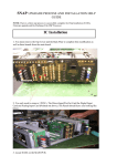
1
Lancer Evolution IX / VIII / VII ACD CLUTCH ASSY RA325101S1 Installation/User Manual Thank you for purchasing our Ralliart product. This installation/user manual explains the procedure for installing this product as well as information on how to use it effectively. Please read this manual carefully to ensure thorough understanding of the details of this product before installation. Give this manual to the customer to save for future reference. Important Safety Notice Please follow the instructions in this manual carefully to ensure proper installation of this product. · This manual contains the following warning symbols: CAUTION This indicates important safety information that must be carefully observed. CAUTION All safety messages that follow this symbol must be carefully observed in order to reduce the risk of personal injury or accidents. NOTICE This indicates information that should be observed when installing parts. · Install the parts to the car as instructed in this manual. · Failure to follow the instructions may hamper the function of this product or cause car trouble. Be aware that Ralliart takes no responsibility for any product malfunction or car trouble that occurs during or after installation of this product. After installing this product, please give the customer this installation/user manual to save for future reference. R023-0212-0604 To the Owner Precautions for Use 1. Do not use or install this product on non-applicable car models. Such installation could result in car damage or accidents. 2. Do not modify or disassemble this product in any manner. 3. If you experience any problems when driving your car after this product is installed, stop your car immediately and have it checked at a repair shop. Failure to do so could result in car damage or accidents. 4. Install this product using only the specified parts supplied in the kit. Do not combine parts of other products into the assembly of this product. 5. Have your car inspected when necessary to maintain normal installation and operating conditions of this product. 6. If the original function of this product cannot be maintained due to damage or deterioration, replace it immediately. Applicable Models Car Model Name Lancer Evolution IX Lancer Evolution VIIIMR / VIII Lancer Evolution VII Model GSR GT RS GSR Transmission Type PARTS NO. 6FM/T 5FM/T CT9A 6FM/T RA325101S1 RS GSR RS 5FM/T Precautions for Installation CAUTION 1. To ensure safety during installation, turn the ignition key to the “OFF” position and set the parking brake firmly. 2. Jack up the car body and firmly support it with a set of jack stands, using only the jacking and support points specified in the Car Owner’s Manual. Failure to use the designated jacking/support points could result in deformation of the body or other parts. NOTICE 3. This Installation/User Manual explains only the essential points of the installation procedure for this product. For further details regarding installation procedure, refer to the Mitsubishi Motors Corporation (MMC) Workshop Manual for your car model. 4. All attachment bolts and nuts should be securely tightened at the specified torque. 5. Install this product using the specified set of parts only. Do not combine parts of other products into the assembly of this product. Special Tools Required MUT-II Sub-assembly (MB991502) Oil pressure gage (MD998330) Adapter (MB991705) Slide hammer (MB991721) R023-0212-0604 1 Kit Contents (Ensure that the following parts are contained in the kit.) ①ACD CLUTCH ASSY 1個 Other Parts Required (The following parts must be purchased separately for installation of this product) Transfer overhaul kit (RA980932S1) R023-0212-0604 2 Installation Procedure 1. Removal of Transfer Assembly Before removing the transfer assembly from the car, drain oil from the transmission and the transfer, and then remove the front exhaust pipe, propeller shaft, and center member. (1) Disconnect the driveshaft LH/RH. *Use a lever to remove the driveshafts. (2) Disconnect the inner shaft. Use the slide hammer (MB991721) to pull out the inner shaft LH/RH. R023-0212-0604 3 Installation Procedure (3) Remove the rear roll stopper attaching bolts, transfer pressure hose, and transfer assembly attaching bolts. NOTICE · Tightening torque for attachment · Specified torque: · Nuts : 52 ±7 Nm (5.3 kgfm) Bolts : 44 ±5 Nm (4.5 kgfm) Bolts : 59 ±9 Nm (6.0 kgfm) After temporarily tightening the Nuts torque them fully with the car body loaded with its engine. (4) Roll the engine and transmission assembly toward the vehicle front with the engine mount and the transmission mount attached on it, and disconnect the transfer assembly between the engine block and the flat cross. CAUTION Beware of not damaging the oil seal lip of the transfer. R023-0212-0604 4 Installation Procedure 2. Removal of Existing ACD Clutch Assembly (1) Remove the bolts of the transfer case. NOTICE · Do not remove the two bolts indicated with arrow marks. (2) Remove the ACD clutch assembly by prying the case cover apart with two drivers. NOTICE · Assembly of the ACD clutch assembly and the differential assembly are pulled out of the transfer case. (3) Pull the differential assembly out of the ACD clutch assembly. R023-0212-0604 5 Installation Procedure 3. Installation of ACD Clutch Assembly (1) Assemble the transfer in the reverse order of the removal procedure. NOTICE · Tightening torque for attachment Specified torque: Bolts : 25 ±5 Nm (2.5 kgfm) 4. Installation of Transfer Assembly (1) Install the transfer assembly on the car in the reverse order of the removal. NOTICE · Specified torque: · Nuts : 52 ±7 Nm (5.3 kgfm) Bolts : 44 ±5 Nm (4.5 kgfm) Bolts : 59 ±9 Nm (6.0 kgfm) After temporarily tightening the Nuts torque them fully with the car body loaded with its engine. R023-0212-0604 6 Installation Procedure 5. Bleeding of ACD Fluid (Refer to the MMC Workshop Manual for the work in detail.) (1) Lift up the car and connect MUT-II to the diagnosis connector. Test for the actuator and operate the hydraulic unit forcedly. (2) Remove the cap of the bleeder screw on the transfer. Attach a vinyl hose and bleed the transfer of air. CAUTION · Replenish the transfer with fluid so that the fluid always remains in the oil reservoir during bleeding. · If air is not bled fully, noise could occur in the hydraulic unit and result in deteriorating the durability of the pump and other components. (3) Check the fluid for its level after completing bleeding. NOTICE · The fluid level in the oil reservoir shall be between MIN and MAX marks. · Specified fluid: Mitsubishi Genuine Dia Queen ATF SP III NOTES R023-0212-0604 7 Reference Information Scheduled Interval for Fluid Change after Installation Periodic replacement item Replacement interval Capacity (dm3) Transfer oil 20,000 km 0.6 Fluid (ACD and Hydraulic unit) 40,000 km 0.9 Product Name Mitsubishi Genuine Dia Queen LSD Gear Oil Mitsubishi Genuine Dia Queen ATF SP III NOTICE · The above fluid change interval is a guideline only. The oil and fluid may deteriorate more quickly depending on its conditions of use. In such cases, it is recommended to replace the oil or fluid sooner than the above recommended interval. NOTES R023-0212-0604 8