1
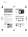
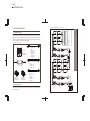
2 colors
PANTONE BLACK 7C
PANTONE 400 M
USER MANUAL
1PXL BOARD CW/WW/DW
1PXL MODULE CW/WW/DW
Please check for the latest updates and changes on the TRAXON website.
© 2008 TRAXON TECHNOLOGIES ALL RIGHTS RESERVED.
WWW.TRAXONTECHNOLOGIES.COM
H O N G
K O N G
N E W
Y O R K
P A R I S
T O K Y O
F R A N K F U R T
B I R M I N G H A M
R O T T E R D A M
Version 1.0
CONTENTS
1. INTRODUCTION ..................................................................1
2. PACKING CONTENTS ........................................................2
3. SAFETY AND OPERATION .................................................3
4. MOUNTING .........................................................................4
4.1 BOARD .........................................................................4
4.2 MODULE .......................................................................4
5. SYSTEM CONFIGURATION ................................................7
5.1 TX CONNECT SYSTEM ................................................7
5.2 SYSTEM CONNECTION ...............................................7
5.3 SETTING AUTO-ADDRESSING ...................................10
5.4 CONNECTING BETWEEN FIXTURES ..........................10
5.5 LED CONTROL ..........................................................11
6. CARE AND MAINTENANCE ..............................................11
7. TECHNICAL SPECIFICATION ...........................................12
8. WARRANTY STATEMENT .................................................12
1 colors
PANTONE BLACK M
• 16/32 Ultra Bright White SMD
LED Board with Housing
222mm/8.740”
62.50mm/2.641”
• DMX Control
OR WEARING ANTISTATIC WRIST STRAP.
• Auto-Addressing
• SMART CHIP™ Technology
250mm/9.843”
• TX Connect™ System
CAUTION: DO NOT OPEN OR HANDLE EXCEPT AT A STATIC FREE WORKSTATION
• Quick Clip Mounting System
1. INTRODUCTION
• Indoor Applications
1PXL BOARD CW (MB.BO.5060000)
36.50mm/1.437”
250mm/9.843”
200mm/7.874”
200mm/7.874”
MANUAL CAREFULLY BEFORE BEGINNING SETUP AND INSTALLATION.
1PXL MODULE CW/WW/DW (Cold White / Warm White / Dynamic White™)
62.50mm/2.641”
222mm/8.740”
FOR YOUR OWN SAFETY AND THAT OF THE PRODUCT, PLEASE READ THIS USER
13.5mm/0.531”
FRONT
SIDE
BACK
1PXL MODULE CW (MB.MO.5060000)
1PXL BOARD WW (MB.BO.5070000)
1PXL MODULE WW (MB.MO.5070000)
1PXL BOARD DW (MB.BO.5080000)
1PXL MODULE DW (MB.MO.5080000)
2. PACKING CONTENTS
The Traxon™ 1PXL Board/Module CW/WW/DW features 16/32 ultra bright white SMD
LEDs on a 4 x 4 matrix with a 62.5mm pitch.
A low-profile and open beam angle ensure optimal integration behind a wide range of
diffuser materials. Designed for backlighting of walls, floors, ceilings, or any other flat
surface that allows you to optimize the color temperature to changing ambients. The
product is designed to be the base element for setting up large LED matrix arrays. It
can either be mounted as a board or used as a module with plastic housing.
The Board/Module is DMX compatible which allows daisy chaining with the Traxon TX
Connect™ system. On-board SMART CHIP™ technology with the powerful feature of
auto-addressing enables easy setup and installation.
1PXL BOARD CW/WW/DW (Cold White / Warm White / Dynamic White™)
230mm/9.06”
• 16/32 Ultra Bright White SMD LED
1PXL BOARD CW/WW/DW
4 x Mounting Spacers
1 x Board
1 x TX Connect Smart Interconnection Cable (30mm/11.82”)
4 x Mounting Screws
1PXL MODULE CW/WW/DW
10.78mm/0.42”
• TX Connect™ System
• Auto-Addressing
• SMART CHIP™ Technology
4 x Screw Caps
230mm/9.06”
• DMX Control
1 x Module
(TX Connect Cables Fitted)
2 x Quick Clip
Mounting Kits
4 x Mounting Screws
1 x Removal Key
• Indoor Applications
1
FRONT
SIDE
BACK
2
1 colors
PANTONE BLACK M
3. SAFETY AND OPERATION
4. MOUNTING
CAUTION – UNPLUG THE POWER SUPPLY FROM THE MAINS POWER BEFORE
4.1 BOARD
CONNECTING ANY CABLES AS THIS CAN DAMAGE THE PRODUCTS.
To mount the Board, first fit the nylon spacers into the mounting holes from the rear of
the board. Then use the screws to firmly fasten the board to a flat surface. Careful not
to over-tighten the screws (see FIG 1).
CAUTION – AVOID LOOKING DIRECTLY INTO THE LED LIGHT SOURCE AT CLOSE
RANGE FOR YOUR OWN SAFETY.
FIG 1: Board Mounting
SPACER
ANY PERSONS INSTALLING THIS PRODUCT SHOULD COMPLY WITH LOCAL
180m
STANDARDS AND REGULATIONS AND MUST BE QUALIFIED FOR THE HANDLING
m/7.0
This product is designed for indoor use only.
Ensure product operate within the ambient temperature range of 0°C to 40°C
(32°F to 104°F).
If the fixture has been subjected to drastic temperature variances, for example, following
transportation, do not connect the fixture until it has reached room temperature, as
moisture condensation may cause electric shock and product damages.
When installing the fixtures and system power supplies, please ensure they will not be
exposed to moisture and extreme heat (and direct sunlight for outdoor products).
Besides, keep a clean operating environment for the fixtures and system power supplies.
9”
125mm/4.92”
OF ELECTRICAL EQUIPMENT.
SCREW
WALL
4.2 MODULE
The Module can be mounted by directly screwing it to the wall or using the Quick Clip
mounting clips.
• DIRECT SCREW MOUNTING
Please study this User Manual thoroughly and check the latest Technical Specification
Sheets available from our website [www.traxontechnologies.com] before setup.
3
For front mounting with screws, position the Module in the desired location and fasten
the mounting screws from the front, taking care not to over tighten as this may damage
the housing. Once all screws have been fixed in place, use the screw caps provided to
cover the screw holes (see FIG 2).
4
1 colors
PANTONE BLACK M
For multi module installation, the provided Quick Clip mounting kit can be used as
mounting aid. Affix the mounting brackets to the rear side of the Module fixtures before
mounting. For the outer most Modules, snap the mounting clips into two (corner
Modules do not require any Quick Clip mounting bracket). Once all Modules have been
hooked together, align them on the desired surface and fasten the mounting screws
from the front (see FIG 2).
FIG 3: Quick Clip Mounting the Module
CENTER
TO CENTER
250mm/9.84”
242mm/9.5”
CENTER TO CENTER
250mm/9.84”
For installations exceeding 1m 2 area, it is recommended to mount the Module in
segments of 4 x 4 modules
CENTER
TO CENTER
242mm/9.5”
CENTER
TO EDGE
FIG 2: Direct Mounting the Module
222mm/8.7”
222mm
/8.7”
Screw caps
FIG 4: Using the Removal Key
Mounting screws
• QUICK CLIP MOUNTING
5
The Module can be mounted by using the Quick Clip mounting clips without screwing
on the module. This allows easy mounting and removal of the module with the aid of
the Removal Key (see FIG 4). First, select the Quick Clip mounting brackets for Centerand Edge-Modules and fix them to any flat surface by the center holes using the
provided screws. Please refer to the measurements specified for Center-to-Center
Module and Center-to-Edge Modules in FIG 3. With the clips screwed in place, position
the module on to the clips and press the four corners firmly to clip the module into
place.
To unmount the module,
first remove the screw
caps by carefully easing it
out from the side. Then
using the Removal Key,
insert it into the screw
hole and push to release
the corner of the module
from the clip. Repeat this
for the other three corners
of the module and then
carefully ease the module
out (see FIG 4).
6
TI.EC.0500000
5m
TI.EC.1000000
10m
3m
5.2 SYSTEM CONNECTION
The fixtures are wired together in a daisy chain using the TX Connect Smart system
(see FIG 6 and FIG 7).
Power back via TX Connect Data Cable
1m
512 DMX Channels per output
TI.EC.0300000
A
0.5m
TI.EC.0100000
CONTROLLER
Part No.: TI.DO.0000100
Part No.:
TI.EC.0050000
TX Connect Data Cable
(DI.IC.xxxxxxx)
512 DMX Channels per output
TX Connect Smart Extension Cable
Light-Drive JOG DW
(SC.JD.5080000)
Part No.: TI.ZI.0000100
0.6m
D
TX Connect Smart
Data Extractor Box
(TI.DO.0000100)
TX Connect Data Cable
OUT
IN
TOP
Back View
OUT
IN
TOP
Back View
POWER SUPPLY to last FIXTURE in chain.
C to D: 30 meters
CONTROLLER to first FIXTURE.
A to B: 100 meters
CABLING LENGTHS
PER CONTROLLER OUTPUT (512 DMX CHANNELS).
170 1PXL BOARD CAN BE DAISY CHAINED
PER LED ENGINE SMART 100W INDOOR.
6 1PXL BOARD DW CAN BE DAISY CHAINED
PER LED ENGINE SMART 100W INDOOR.
12 1PXL BOARD CW/WW CAN BE DAISY CHAINED
OUT
IN
TOP
Back View
OUT
IN
TOP
Back View
CAUTION: PLEASE ENSURE THAT THE POWER IS SWITCHED OFF WHEN THE
DATA CABLES ARE BEING CONNECTED. FAILURE TO DO SO WILL RESULT IN
DAMAGE TO THE PRODUCTS AND VOID THE PRODUCT WARRANTY.
TX Connect Smart Extension Cable
(TI.EC.xxxxxxx)
OUT
OUT
TX Connect Smart
Interconnection Cable
(TI.IC.xxxxxxx)
IN
IN
TOP
Back View
OUT
OUT
TOP
Back View
IN
TOP
Back View
FIG 5: TX Connect System Components
AC Power Cord
(PS.AC.xxxxxxx)
TX Connect Smart
Data Extractor Box
0.3m
TI.IC.0060000
POWER SUPPLY
TX Connect Smart
Power/Data Injector Box
0.08m
TI.IC.0030000
100W Indoor
(PS.IA.0010000)
Part No.: PS.IA.0010000
Part No.:
TI.IC.0008000
LED Engine Smart
LED Engine Smart 100W Indoor
TX Connect Smart Interconnection Cable
IN
20m
TOP
Back View
DI.IC.2000000
C
10m
OUT
5m
DI.IC.1000000
IN
DI.IC.0500000
OUT
3m
SC.JD.5080000 (black)
SC.JD.5080100 (white)
IN
DI.IC.0300000
TX Connect Smart
1m
Part No.:
Interconnection Cable
(TI.IC.xxxxxxx)
0.2m
DI.IC.0100000
TOP
Back View
Part No.:
DI.IC.0020000
(TI.ZI.0000100)
Light-Drive Jog DW
B
The Traxon TX Connect System is a interconnection system that combines power and
DMX data on a single connector cable so that only one connection is required between
light fixtures. The Board/Module uses TX Connect System for all interconnections. FIG 5
shows some components for the TX Connect System:
TOP
Back View
5.1 TX CONNECT SYSTEM
TX Connect Smart
Power/Data Injector Box
5. SYSTEM CONFIGURATION
TX Connect Smart Interconnection Cable (TI.IC.xxxxxxx)
AC IN
7
DC OUT
1 colors
PANTONE BLACK M
FIG 6: 1PXL Board CW/WW/DW System Connection Example
8
9
C
A
512 DMX Channels per output
TX Connect Data Cable
(DI.IC.xxxxxxx)
512 DMX Channels per output
Power back via TX Connect Data Cable
CONTROLLER
Light-Drive JOG DW
(SC.JD.5080000)
AC Power Cord
(PS.AC.xxxxxxx)
POWER SUPPLY
LED Engine Smart
100W Indoor
(PS.IA.0010000)
TX Connect Smart
Interconnection Cable
(TI.IC.xxxxxxx)
TX Connect Smart
Power/Data Injector Box
(TI.ZI.0000100)
IN
IN
TOP
Back View
OUT
TOP
Back View
TOP
Back View
TOP
Back View
OUT
TOP
Back View
TOP
Back View
TX Connect Smart Extension Cable
(TI.EC.xxxxxxx)
IN
IN
TX Connect Smart
Data Extractor Box
(TI.DO.0000100)
OUT
TOP
Back View
TOP
Back View
IN
OUT
TOP
Back View
TOP
Back View
POWER SUPPLY to last FIXTURE in chain.
C to D: 30 meters
CONTROLLER to first FIXTURE.
A to B: 100 meters
CABLING LENGTHS
PER CONTROLLER OUTPUT (512 DMX CHANNELS).
170 1PXL MODULE CAN BE DAISY CHAINED
PER LED ENGINE SMART 100W INDOOR.
6 1PXL MODULE DW CAN BE DAISY CHAINED
PER LED ENGINE SMART 100W INDOOR.
12 1PXL MODULE CW/WW CAN BE DAISY CHAINED
IN
CAUTION: PLEASE ENSURE THAT THE POWER IS SWITCHED OFF WHEN THE
DATA CABLES ARE BEING CONNECTED. FAILURE TO DO SO WILL RESULT IN
DAMAGE TO THE PRODUCTS AND VOID THE PRODUCT WARRANTY.
1PXL Module CW (MB.MO.5060000)
1PXL Module WW (MB.MO.5070000)
1PXL Module DW (MB.MO.5080000)
D
B
TX Connect Smart Interconnection Cable (TI.IC.xxxxxxx)
1 colors
PANTONE BLACK M
FIG 7: 1PXL Module CW/WW/DW System Connection Example
5.3 SETTING AUTO-ADDRESSING (DEFAULT OFF)
By default, the factory setting for the auto-addressing feature is OFF. The DIP switch
on the back of the fixture sets the auto-addressing feature (see FIG 8).
Auto-addressing sets the DMX channel for the next fixture in the chain.
FIG 8: Auto-Addressing Switch
BOARD
AUTO-ADDRESSING OFF
MODULE
AUTO-ADDRESSING ON
BACK VIEW
BACK VIEW
• Auto-addressing OFF: Next fixture uses the same DMX data as the existing fixture.
• Auto-addressing ON: Next fixture uses data from the next 3 DMX channels
5.4 CONNECTING BETWEEN FIXTURES
Use the TX Connect Smart Interconnection Cable to connect between boards. Use the
pre-installed cables to connect between Modules. For longer distances, use existing
cable together with a TX Connect Smart Extension Cable.
FIG 9: Connecting Fixtures
BOARD CONNECTION
MODULE CONNECTION
10
1 colors
PANTONE BLACK M
5.5 LED CONTROL
7. TECHNICAL SPECIFICATION
The LEDs on the 1PXL Board CW/WW/DW and 1PXL Module CW/WW/DW are
controlled by DMX. Each fixture is allocated with 3 DMX channels that control the
brightness for CW/WW (cold white/warm white) fixtures; and the brightness and color
temperature for DW (dynamic white) fixtures. Refer to the table below.
CW FIXTURE
WW FIXTURE
DW FIXTURE
CHANNEL 1
CHANNEL 2
CHANNEL 3
—
0-255
Reserved
0-255
—
Reserved
0-255
0-255
Reserved
WHERE:
0 = MIN. INTENSITY
255 = MAX. INTENSITY
6. CARE AND MAINTENANCE
Traxon™ products are of superior design and quality and should be treated with
care. The recommendations below will help fulfill and warranty obligations and
gain good use and longevity from the products.
- Do not attempt or use the product(s) until you read and understand the installation instructions.
Failure to adhere to these instructions could result in serious injury or property damage.
- Do not use product(s) if cables are damaged.
- Do not use product(s) when wet or in wet area. Moisture can cause electric shock and damage to
product(s).
- Do not use product(s) in dirty and dusty environment.
- Do not use product(s) in extreme heat environment. Ensure there is sufficient airflow and use cool
air circulation if required.
1PXL BOARD CW/WW/DW / 1PXL MODULE CW/WW/DW
Color Temperature:
Light Source:
Source Life:
Beam Angle:
Power Input:
Power Consumption:
Operating Temperature:
7000 K (CW), 3500 K (WW), 3500-7000 K (DW)
16 (CW/WW) or 32 (DW) Ultra Bright SMD LED
50,000 hours under normal operating conditions
120°
24V DC
8W max. (CW/WW), 15W max. (DW)
0°C to 40°C (32°F to 104°F)
As with all electronic devices, LED output degrades over time - a term called lumen
depreciation. This also explains why it is nearly impossible to expect photometric
performances of two LED products with different service life spans to be the same. The
rate of LED degradation is a complex function of many factors such as operating
efficiency, duration of continuous operation, and operating conditions (e.g. ambient
temperature).
Because LEDs are semiconductor devices, their performances are subject to inherent
variability commonly found in semiconductor industry. To improve consistency in
performance across the same product. LED manufacturers “sort” LEDs into bins
according to different preset parameters, such as forward driving voltage, illumination,
etc. Whereas binning is a sorting function, it is not a correction process. Inherent
variability in the manufacturing process results always in different binning distributions
according to different production lots. Traxon uses automatically binned LEDs on its
products, thereby minimizing output variations within the model range.
- Do not drop, knock, or shake product(s). Rough handling can damage the electronics and void the
warranty.
- Do not use harsh chemicals, cleaning solvents, or strong detergents to clean products. Wipe with
a damp cloth on housings and a dry cloth on electronics to remove dirt or dust.
- Do not use product(s) outdoors.
- Do not attempt to service or repair the product(s) unless done by an authorized service personnel.
Contact your the local Traxon™ office or distributor for details.
11
If the product is not working correctly, please contact your nearest authorized service
centre or Traxon Technologies office for assistance.
8. WARRANTY STATEMENT
Traxon warrants its Products against material or workmanship defects for a period of
two (2) years from date of purchase, provided that the purchased items are used under
the conditions stated in this user manual.
Please refer to the Product Warranty section under www.traxontechnologies.com/terms
for warranty terms and conditions.
12