1
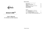
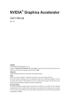
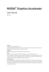
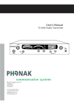
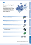
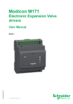
User Manual
PCD2.G200
User Manual
Document 27/635; Version EN02 │ 2014-02-18
Saia-Burgess Controls AGFehler! Verwenden Sie die Registerkarte 'Start', um Heading 1 dem Text zuzuwe
Table of contents
1
Overview PCD2.G200...........................................................................................3
2
2.1
2.2
2.3
Specifications ......................................................................................................4
Resolution..............................................................................................................6
Dip Switch position ................................................................................................6
I/O connection .......................................................................................................6
3
3.1
3.2
3.2.1
3.2.2
Preparing the PLC system ..................................................................................7
CPU FW ................................................................................................................7
Preparing PG5 .......................................................................................................7
Device configurator ................................................................................................8
Media mapping .................................................................................................... 10
4
Example of linearization .................................................................................... 11
5
Contact ...............................................................................................................12
Document 27/635; Version EN02 │ 2014-02-18
2
Saia-Burgess Controls AG
Overview
Document revisions
Revision Date
EN01
2013-10-07
EN02
2014-02-19
Modified
2013-10-07
div. corrections
Comments
New document
1 Overview PCD2.G200
The PCD2.G200 is a double I/O-module that uses two I/O-slots and includes the following functions :
- 4 digital outputs 24VDC
- 4 digital inputs 24VDC
- 8 analogue inputs 12bit (2 x 0 … 10V, 4 x selectable 0 … 10V, Pt/Ni1000 or 0 … 20mA, 2 x Pt/Ni 1000
- 8 analogue outputs 0...10V (10 Bit)
Figure 1: Modul Übersicht
Document 27/635; Version EN02 │ 2014-02-18
3
Saia-Burgess Controls AG
Fehler! Verweisquelle konnte nicht gefunden werden.
2 Specifications
Technical data
COMPATIBILITY
Storage temperature
Ambient temperature operating
Relative air humidity
POWER
PCD1, PCD2
-25…+70 °C
0…+55 °C
10…95% r.h. non condensing
+5V and V+ IOBUS
And 24V ext. for digital outputs
12mA on +5V and max. 35mA on V+
No
Module power supply voltage
Current consumption
Galvanic separation
DIGITAL OUTPUTS
Number of outputs
Addressing
Voltage range
Output current
4, electrically connected, source operation
O 0 ..3 (+BA)
10…32 VDC, smoothed, max. 10% residual ripple
5…500 mA (leakage current max. 0,1 mA)
min. load resistance: 48Ω
yes
max. 0.3 V at 0.5 A
Typically 50 µs, max. 100 µs for resistive load
TVS 39V
yes
1 plug-in spring-load terminal block, 10-pole, 3.5mm
for wiring up to 1mm2, black
Short circuit protection
Voltage drop
Output delay
Overvoltage protection
LEDs
Terminals
DIGITAL INPUTS
Number of inputs
Addressing
Input voltage
4, electrically connected, source operation
I 4 ..7 (+BA)
Typ. 24 VDC smoothed or pulsed
H level: 15…30V
L level: -30…+5V
typ. 7 mA at 24 VDC (IEC 61131-2, Typ 1)
typ. 8 ms
no (Umax = +/-34V)
yes
1 plug-in spring-load terminal block, 10-pole, 3.5mm
for wiring up to 1mm2, black
Input current
Input delay
Overvoltage protection
LEDs
Terminals
Figure 2: Technical Data
Document 27/635; Version EN02 │ 2014-02-18
4
Saia-Burgess Controls AG
Technische Daten
Technical data
ANALOGUE INPUTS
Number of inputs
Confiquration
Galvanic separation
Signal ranges
Resolution (digital representation)
Connection technique for sensors
Measuring principle
Input resistance
Input filter
Input ranges for temperature sensors
Accuracy at 25°C
Temperature error (0…+55°C)
Overrange protection
Terminals
ANALOGUE OUPUTS
Number of outputs
Galvanic separation
Signal ranges
Resolution (digital representation)
Accuracy at 25°C
Temperature error (0…+55°C)
Load resistance
Short-circuit protection
Terminals
8
AI0 / AI1
0…10V
AI2 / AI3 / AI4 / AI5: Dip Switch selectable
AI6 / AI7
PT/NI1000
no
0…10 V Resolution*) 2.44 mV
0…20 mA, Resolution*) 4.88 µA
*) Resolution = value of least significant bit (LSB)
12 bits (0…4095) rsp. directly in 1/10 °C or in 0.1Ω
2-wires (passiv input)
Single ended
10V range:
20kΩ
20mA range:
125Ω
PT/NI1000:
7.5kΩ
typ.
10 ms (0…10V)
typ.
20 ms (0…20mA; PT/NI1000)
PT1000: -50…+400°C
NI1000: -60…+200°C
NI1000L&S -60…+200°C
Resistance 0 … 2500 Ω
Resistance 0 … 300 kΩ
± 0.5% (±0.4% ±4LSB)
± 0.25%
10V range: + 35V (39V TVS Diode)
20mA range: no ( 40mA max.)
1 plug-in spring-load terminal block, 10-pole, 3.5mm
for wiring up to 1mm2, orange
8
no
0…10 V Resolution 10 mV, LSB (least significant bit)
10 bits (0…1023)
± 0.5% ± 50mV
± 0.25%
min. 3kΩ
yes, permanent
1 plug-in spring-load terminal block, 10-pole,
3.5mm for wiring up to 1mm2, orange
Table 1: Technical data of the module
Document 27/635; Version EN02 │ 2014-02-18
5
Saia-Burgess Controls AG
Fehler! Verweisquelle konnte nicht gefunden werden.
2.1 Resolution
Mode
Voltage
0 ... +10V
Current
0…+20mA
Resistance
0...2'500 Ω
Resistance
0...300 kΩ
Pt 1000
Ni 1000
Ni 1000 L&S
Resolution
[analogue]
Resolution
[digital]
1mV
0…+10‘000
5.14 uA (linear)
1uA
0…+20‘000
0.50... 0.80 Ω
0.1Ω
0...25’000
1Ω
0..300’000
0.1°C
0.1°C
0.1°C
-500...4000
-600...2000
-600...2000
2.44 mV (linear)
0...10kΩ:
10k...20kΩ
20k…40kΩ:
40k...70kΩ:
70k...100kΩ:
100k...300kΩ:
-50...+400°C:
-60 ... +200°C:
-60 ... +200°C:
2...14 Ω
14…40 Ω
40..130 Ω
130..350 Ω
350...700 Ω
0.7...4.5 kΩ
0.15 ... 0.25°C
0.09 ... 0.11°C
0.12 ... 0.15°C
Table 2: Resolution of the module
Read Values
2.2 Dip Switch position
The input circuit for the analogue inputs AI2 .. AI5 can be selected by mini Dip switches:
Figure 3: DIP Switches
The modes T (NI/PT1000), C (0..20mA) or V (0..10V) are selected by putting the switch in the down
position. Only one switch per channel has to be on, except in the 0..300kΩ range where the T and the
V switch must be on.
The above picture shows the default setting (all on T) where all inputs are configured in the
temperature measurement mode.
2.3 I/O connection
4 plug-in spring-load terminal blocks, 10-pole, 3.5mm for wiring up to 1mm2
Weidmüller Type K. Orange: Part No. 4 405 5048 0, black Part No. 4 405 5054 0
Figure 4: Inputs connections
Handbuch PCD2.G200 │ Dokument 27/635; Version DE02 │ 2014-02-18
6
Saia-Burgess Controls AG
SW / FW
3 Preparing the PLC system
3.1 CPU FW
The analog inputs/outputs can be mapped in the device configurator.
Therefore the PCD firmware must be version PCD1.M2xx0_1.22.28 rsp. PCD2.M5xx0_1.22.28 or
newer.
Older PCD’s can be updated by downloading a new FW with the PG5 firmware download tool:
Figure 5: Firmware Downloader Tool
Actual FW can be find on the support website www.sbc-support.com
3.2 Preparing PG5
The G200 module can only be used with the software version PG5 2.1.200 or newer.
Please, verify if your system is up-to-date. You find the last PG5 version on the support Website
www.sbc-support.com
From PG5 version V2.1.300 on the G200 is fully supported.
For older versions the following templates:
- pcd2multifunction.saiaxml
G200 configuration
- pcd1mxxx0.saiaxml
PCD1 modul selection
- pcd2mxx0.saiaxml
PCD2 modul selection
Have to be copied in the template directory.
Example: C:/Program Files (x86)/Saia-Burgess/PG5 V2.1.200/DeviceTemplates
Document 27/635; Version EN02 │ 2014-02-18
7
Saia-Burgess Controls AG
Symbole
3.2.1 Device configurator
3.2.1.1 Choosing the module
The PCD2.G200 can be selected from the Multi-Function Modules and placed on Slot0 for PCD1 :
Figure 6: Device Configurator
For PCD2 systems only the even slots (0,2,4,6) are allowed.
3.2.1.2 Configuring Analog Inputs
The Media Mapping for analog inputs and outputs has to be set to Yes:
Figure 7: Mapping Analogues Inputs
For each analog input there are several resolution options to select :
Analog inputs 0 and 1 can be set to 0..10000mV or user defined range or to non converted 12 bit
values 0..4095:
Figure 8: Range selection AI0 / AI1
The default user range is 0 .. 1000
Document 27/635; Version EN02 │ 2014-02-18
8
Saia-Burgess Controls AG
Device Configurator
The Analog Inputs 2 to 5 (with the DIP switches) havethe following possibilities :
Figure 9: Range selection AI2 .. AI5
The selected resolution has to correspond with the DIP switch position on the G200.
There is no automatic recognition when uploading the configuration from the CPU since the DIP
switch position can not be read by the CPU.
For the Analog Inputs 6 and 7 there are the following options :
Figure 10: Range selection AI6 / AI7
3.2.1.3 Configuring Analog Outputs
Each analog output can be configured to 0…10000mV or 10bit values 0…1923 or to any other user
defined range:
Figure 11: Range selection Analogues Outputs
Additionally a reset value can be specified:
Figure 12: Reset value Analogues Outputs
3.2.1.4 Configuring Digital Inputs / Outputs
The digital Outputs can be addressed directly on O 0 .. O 3 (+BaseAddress of the slot).
The digital Inputs can be addressed directly on I 4 .. I 7 (+BaseAddress of the slot).
They can also be mapped like any standard digital module.
Handbuch PCD2.G200 │ Dokument 27/635; Version DE02 │ 2014-02-18
9
Saia-Burgess Controls AG
Device Configurator
3.2.2 Media mapping
With media mapping, each G200 module uses the following registers:
Figure 13: PG5, media mapping
In the user program the analogue I/O’s are accessed with the symbols:
Example: set Analog Output2 to 5V :
LD
5000
IO.Slot0.AnalogueOutput2
; range selected= 10000mV
The CPU reads the inputs at before executing the COB and updates the outputs after executing the
COB.
For „mixed“ I/O Modules as the G200 the digital outputs have also a input symbol
IO.Slot0.RdDigitalOutput0...3 , but these are not used in this case.
To write the outputs only the symbols IO.Slot0.WrDigitalOutput0...3 are used.
The effective addresses can be seen in the Data List View:
Figure 14: effective addresses
Handbuch PCD2.G200 │ Dokument 27/635; Version DE02 │ 2014-02-18
10
Saia-Burgess Controls AG
Linearization
4 Example of linearization
NTC sensors are not inplemented in the Device Configurator because these sensors are not
standardized. To use a NTC with the module PCD2.G200, please configure the desired channel in mode
“0..300kΩ” and use the linearization FBox available in PG5 environment.
In the FBox the resistance values of the sensor have to be entered that the conversion to a
temperature is executed.
A project example can be downloaded from the SBC Support Website:
http://www.sbc-support.com/en/services/getting-started/programm-examples/pg5-21/general.html
Document 27/635; Version EN02 │ 2014-02-18
11
Saia-Burgess Controls AG
Contact
5 Contact
Saia-Burgess Controls AG
Bahnhofstrasse 18
CH-3280 Murten / Switzerland
Phone: ...........................................
Fax: ................................................
E-Mail Support: .............................
Supportpage: .................................
SBC page: .......................................
+41 26 672 72 72
+41 26 672 74 99
[email protected]
www.sbc-support.com
www.saia-pcd.com
International Represetatives &
SBC Sales Companies:: .................. www.saia-pcd.com/contact
Postal address for returns from customers of the Swiss Sales office
Saia-Burgess Controls AG
Service Après-Vente
Bahnhofstrasse 18
3280 Murten
Switzerland
Document 27/635; Version EN02 │ 2014-02-18
12