1
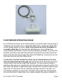
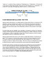
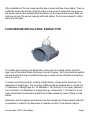
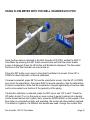
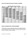
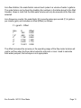
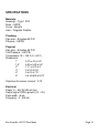
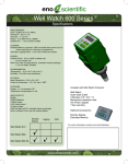
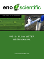
LEVEL AND FLOW MEASUREMENT
WS131 FLOW METER
USER MANUAL
www.enoscientific.com
Eno Scientific
PO Box 1586
Hillsborough, NC 27278
USA
www.enoscientific.com
910-778-2660
Copyright Notice
Copyright © 2015 Eno Scientific, Hillsborough, NC 27278, USA.
All rights reserved.
Part number: 5400-901-2015
WS131 FLOW METER
USER MANUAL
Table of Contents
PRODUCT OVERVIEW................................................................................................. 4
FLOW SENSOR OPERATING RANGE.........................................................................5
FLOW SENSOR INSTALLATION: TEE TYPE...............................................................6
FLOW SENSOR INSTALLATION: SADDLE TYPE........................................................7
FLOW SENSOR INSTALLATION: ELECTRICAL...........................................................9
USING FLOW METER WITH THE WELL SOUNDER 2010 PRO ...............................10
SCALE FACTORS FOR USE WITH THE WELL SOUNDER.......................................12
USING FLOW METER WITH OTHER EQUIPMENT...................................................12
SPECIFICATIONS........................................................................................................ 14
WARRANTY AND SERVICE........................................................................................15
PRODUCT OVERVIEW
The Eno Scientific paddle wheel flow meters measure water flow by converting the
rotation of the internal paddle wheel into a number of electrical pulses proportional to
the amount of water passing through. For PVC pipe sizes 1”, 1.5” and 2”, the flow
meter is a modular unit resembling a pipe tee with PVC slip type pipe connections on
the run and a socket on the branch to mount the sensor unit. The housings are made
of PVC with sockets for schedule 40 PVC pipe connections. For pipe sizes of 3”, 4”,
and 6”, the flow meter housing is a 2 piece saddle which clamps onto an existing pipe
and provides a socket for the flow meter sensor. The sensor unit contains the paddle
wheel and electronics, and easily mounts to any of the housing sizes with a simple
hand-tightened ring nut. The PVC tee housings are designed to permanently install at
the test site to provide a socket for the flow sensor. The sensor can be connected while
testing is under way, then can then be removed and replaced with a cap for future
testing. Alternatively, some people prefer to attach threaded fittings to the housing to
allow reuse.
The output from the sensor unit can be plugged into an Eno Scientific Well Sounder
2010 PRO for data collection and readout. It is designed to use very little power to
conserve battery life.
Additional housings, caps and other accessories are available from your local
distributor or on our website at www.enoscientific.com.
Eno Scientific WS131 Flow Meter
Page 4
FLOW SENSOR OPERATING RANGE
Eno Scientific flow sensors use a rotating impeller to sense the water moving through a
closed pipe. As the water moves, it drags the paddles with it, producing a digital pulse
as each paddle passes the sensor. Note: The pipe must be full for the impeller to
accurately reflect flow. As the water flow rate decreases, it has a harder time
overcoming the small friction in the rotor and the efficiency decreases. The scale factor
therefore increases as the water flow decreases showing that more water passes per
pulse at low flow rates than at higher flow rates and dramatically increases at very low
flow rates. (See the scale factor table below.)
It is therefore important that the flow meter size be selected based on the flow
rate to be measured and not the pipe size. Select the size for which the scale factor
is most uniform over the flow range to be measured. The most common mistake in
selecting a flow sensor is to oversize the unit and not be able to measure low flow. The
flow sensor will operate at significantly higher velocities than commonly used for sizing
pipe. Note: a 2” flow sensor has an operating range high enough for use with 3 or 4
inch diameter pipelines running at lower velocities. If the system flow rate falls below
the minimum shown in these tables, use a smaller diameter flow sensor installed in a
Eno Scientific WS131 Flow Meter
Page 5
“meter run”- a section of pipe containing 10 diameters (ex. 10 diameters = 30 inches for
3 inch pipe) of straight pipe ahead of the sensor and 5 diameters (ex. 5 diameters = 15
inches for 3 inch pipe) of straight pipe after the sensor, as shown below.
FLOW SENSOR INSTALLATION: TEE TYPE
Always install a flow sensor in a straight section of pipe where there is a minimum of 10
diameters upstream (ahead) and a minimum of 5 diameters downstream (behind) of
the flow sensor. Pipe bends, other fittings, valves, pipe enlargements or reductions or
anything else that would cause a flow disturbance should not be present in this length
of pipe.
The flow meter may be installed in any orientation, horizontal or vertical. It is important,
however, that the pipe be full of water without trapped air or debris. With this in mind, in
a vertical pipe, up flow is preferable to down flow. Orient the sensor so that it is easily
removable for service or replacement with a cap.
Always install with the flow arrow on the sensor pointed downstream, and allowing at
least 3 3/4” clearance to remove flow sensor insert from the tee housing for service.
The sensor tees are usually installed with the insert located in the 12:00 o’clock or
straight up position to make removal easier. Be sure to leave an adequate loop of wire
to allow the sensor insert to be removed for service while still remaining attached.
The PVC pipe sockets on the tee type housings are intended to be solvent welded to
the PVC pipe using standard solvent welding techniques. Threaded connectors or
unions may be welded to the tee for a removable installation. Disassemble the flow
sensor before joining the tee to the piping system. Remove the flow sensor from the
housing by loosening the retaining nut by turning it counter-clockwise then pulling the
sensor housing straight out. Caution: do not pull by the wires!
Eno Scientific WS131 Flow Meter
Page 6
After installation of the tee, make sure the pipe is clean and free of any debris. Then reinstall the sensor into the tee. Align the ridge on the sensor housing with the groove in
the sensor socket, then carefully slide the sensor all the way into the socket. Slide the
retaining nut over the sensor housing and hand tighten. Do not use a sealant or teflon
tape on the threads.
FLOW SENSOR INSTALLATION: SADDLE TYPE
The saddle type housings are designed to clamp onto an existing section of sch40
pipe, over a hole which allows the sensor to enter the pipe. An o-ring inside the saddle
will seal around the hole provided that the pipe is clean and smooth without scratches,
burrs, or rust etc.
To select a mounting location, locate a straight section of pipe with a minimum of 15
diameters of straight pipe. The mounting saddle should be installed with a minimum of
10 diameters of straight pipe (ex. 10 diameters = 30 inches for 3 inch pipe), upstream
and a minimum of 5 diameters of straight pipe (ex. 5 diameters = 15 inches for 3 inch
pipe) downstream to eliminate irregular flow profiles caused by valves, fittings or pipe
bends.
Remember that the pipeline must be full, free from trapped air, floating debris and built
up sediment in order for the flow meter to operate correctly. Flow sensors may be
Eno Scientific WS131 Flow Meter
Page 7
installed on vertical sections of pipe providing that the piping is full and does not
contain trapped air. A vertical pipe with rising flow is preferred over falling flow. The
sensor housing may be oriented in any direction radially around the pipe.
Clean a 12 inch (minimum) section of pipe 10 diameters downstream of any valve,
fitting or change in size to mount the saddle.
Always install with the flow arrow on the sensor pointed downstream, and allowing at
least 3 3/4” clearance to remove flow sensor insert from the saddle for service. The
saddle is usually installed with the housing up in the vertical or 12:00 o’clock position.
However, if necessary, it may be installed with sensor housing at an angle from vertical
to provide clearance.
Use a 1 3⁄4 inch hole saw, NO SMALLER NOR LARGER, to drill the entry hole in the
center of the cleaned area of the empty depressurized pipe. Make sure the hole is
perpendicular to the pipe and centered. Remove the pipe coupon with the saw; do not
allow it to fall into the pipe. Remove the burr from the edge of the hole.
Make sure the o-ring seal is in place on the underside of the saddle around the
protruding sensor housing.
Place the top half of the saddle with the alignment slot inside the sensor housing on the
downstream side, over the pipe so that the mount fits into the drilled hole.
Attach the bottom half of the saddle to the top half on the hinged side of the top half
and close it around the pipe.
Push the larger end of the tapered wedge over the guides sliding it until the saddle
halves are clamped together. The wedge should go on half-way by hand. Finish setting
wedge with a couple of taps with a rubber mallet.
Make sure that the pipe is clean and free of any debris. Then reassemble the flow
sensor insert with the arrow on the top of the housing in the downstream direction. This
will align the guide key on the insert with the slot inside the housing. Push straight in so
that the key enters the slot until the o-ring seals the opening. Slide the retaining nut
over the wire leads and tighten by hand turning it clockwise. Do not use a sealant or
teflon tape on the threads.
Eno Scientific WS131 Flow Meter
Page 8
FLOW SENSOR INSTALLATION: ELECTRICAL
The flow sensor is available in a variety of configurations. The standard configuration
includes a plugged cable which plugs directly into the Well Sounder 2010 PRO. The
sensor is also available as a special order with a two or three wire connection for
specific data collection equipment.
1 – Installation of the standard sensor for use with the Eno Scientific Well Sounder is
simple. Plug the cable into the compatible connector on the Well Sounder. Where the
connector is occupied by another device such as the probe, a splitter is available to
provide sockets for both devices. An extension cable is available if the flowmeter is to
be mounted more than 6 feet from the Well Sounder connection point.
2 – The 3 wire sensor configuration can be used with the Well Sounder or other
equipment accepting pulsed inputs. The three leeds must be connected as follow:
Black
signal and power ground
Red
power 5 – 12 VDC
Brown signal
Caution: improper connection may damage or destroy the sensor.
Attachment to a Well Sounder with this configuration requires a breakout adapter
(available as an option) which provides a plugged connection to the Well Sounder on
one end and terminals on the other end for the connection of the sensor leeds.
If the sensor is to be mounted more than 4 feet from the connection point, the leeds
can be spliced and extended using wire as small as #28 AWG up to 300 feet. On runs
of more than 20 feet, it is recommended that shielded cable be used and that the shield
be tied to a good earth ground. Otherwise lightning induced transients may damage the
sensor or other equipment.
3 – The 2 wire configurations vary with the type of equipment to be used. Please
contact Eno Scientific Sales for specific requests.
Eno Scientific WS131 Flow Meter
Page 9
USING FLOW METER WITH THE WELL SOUNDER 2010 PRO
Once the flow meter is attached to the Well Sounder 2010 PRO, enable the WS131
Flow Meter by pressing the SET button several times until the flow meter enable
screen is displayed. Press the UP button until Enabled is displayed. The flow meter
functions in the Well Sounder are now turned on.
Press the SET button once more to show the Flow Meter Cal screen. Press UP or
DOWN to select Automatic or Manual calibration.
If manual is selected, press SET to see the scale factor screen. Use the UP or DOWN
keys to set the scale factor, then press DISP to resume operation. See the table below
to select a scale factor. Note that the scale factor changes significantly at low flow rates
and to some extent as a function of the geometry of the piping.
If automatic calibration is selected, press the SET key to see “UP to start”. Press the
UP button to start. Turn on the pump or open a valve to pump 5 gallons into a bucket.
As the bucket reaches the 5 gallon mark, press the DOWN button on the keypad. If the
flow meter is connected correctly and operating, the screen will show Gallons pumped.
The default is 5 gallons, if a different size bucket was used, change this number then
Eno Scientific WS131 Flow Meter
Page 10
press ENTER. Calibration is complete and has compensated for any irregularities of
the installation. The screen will show the scale factor determined and will allow
adjustment or press DISP to resume operation.
Once the display mode is active, press the DOWN button to see the new flow meter
information screens, Flow, Flow rate and Recov rate.
Flow - Displays the total water through the flow meter in gallons or liters if in metric
mode. The total can be reset by pressing the ENTER button while viewing on the
display.
Flow Rate – Displays the rate at which water is flowing through the flow meter in
gallons per minute (liters/minute). The flow rate displays a running average of the flow
per time. The flow rate may appear to not be very responsive as a result. An instant
reading can be obtained by pressing the ENTER button while viewing the flow rate.
This clears the running average and starts over.
Recov Rate – Displays the instantaneous recovery rate of the well. This is the net
difference between the change in the level of the well and the water being pumped
from the well. This value is also filtered with a running average which can be reset by
pressing the ENTER button as above.
Eno Scientific WS131 Flow Meter
Page 11
SCALE FACTORS FOR USE WITH THE WELL SOUNDER
USING FLOW METER WITH OTHER EQUIPMENT
The flow meter can be used with data loggers which can count pulses and accept a
TTL level signal or a switch to ground signal. The data can be configured as a totalizer
tracking the total water pumped or as a frequency counter tracking the instantaneous
flow rate. The calibration constants are different.
Eno Scientific WS131 Flow Meter
Page 12
As a flow totalizer, the scale factors convert each pulse to a volume of water in gallons.
The scale factors can be found by doubling the numbers in the table above for the Well
Sounder. Keep in mind that the total water volume will only be accurate at the flow rate
selected.
As a frequency counter, the scale factor (K) converts pulses per second (F) to gallons
per minute (gpm) and includes an offset (Offset) as follows:
F = gpm/K – Offset
Size
1”
1.5”
2”
3”
4”
6”
K
.322
.650
1.192
2.750
4.530
10.401
Offset
0.200
0.750
0.940
1.580
1.110
3.308
The offset increases the accuracy in the operating range of the flow meter but also will
yield a net flow when the flow rate is below the minimum or zero. Used to calculate
total water pumped, this technique is not appropriate.
Eno Scientific WS131 Flow Meter
Page 13
SPECIFICATIONS
Materials:
Housings – Type 1 PVC
Rotor – HDPE
O-ring – Buna N
Axle – Tungsten Carbide
Plumbing:
Pipe size – Schedule 40 PVC
Pressure - 240PSI
Physical:
Pipe size – Schedule 40 PVC
Test Pressure – 240 PSI
Temperature: 32 – 140 F (0 – 60 C)
Dimensions:
1”
5.75 x 4.5 x 2.4”
1.5”
6.25 x 5.25 x 2.4”
2”
7.11 x 5.75 x 3”
3”
5 x 5.5 x 6.5”
4”
5 x 6.5 x 7.5”
6”
5.5 x 8.625 x 8.75”
Clearance for sensor removal: 3.75”
Electrical:
Power: 5 – 24V @ 500 uA max
Output signal: Pull-to-ground (+V – 0V)
Pulse width: ~5mS
Frequency: .3 – 200 Hz
Eno Scientific WS131 Flow Meter
Page 14
WARRANTY AND SERVICE
Eno Scientific warrants to the user that all products manufactured by Eno Scientific, will
be free from defects in workmanship and materials for 1 year from the date of
shipment.
Eno Scientific warrants to repair or replace any such defective equipment or part
(determined to our satisfaction to have a defect in workmanship or original material)
upon receipt and inspection of such defective equipment to Eno Scientific with all
shipping pre paid by the user.
In no event shall Eno Scientific be liable for any direct, indirect or consequential
damages, abuse, acts of third parties (rental equipment), environmental conditions or
other expenses which may arise in connection with such defective equipment. This
warranty shall not apply to damage of equipment caused by incorrect installation,
usage, lightning, storage, alteration or inadequate care.
This warranty does not apply to parts, assemblies or devices not manufactured by Eno
Scientific which are covered by other manufacturers’ warranties. There are no
warranties except as specifically provided in writing herein.
Contact Eno Scientific with any warranty or service questions.
For additional information, please visit our website at www.enoscientific.com.
Eno Scientific WS131 Flow Meter
Page 15
Eno Scientific WS131 Flow Meter
Page 16