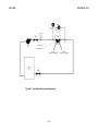
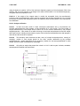
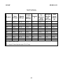
1
NSF International Standard /
American National Standard
NSF/ANSI 50 - 2015
Equipment for Swimming Pools, Spas,
Hot Tubs and Other Recreational
Water Facilities
NSF International, an independent, notfor-profit, non-governmental organization,
is dedicated to being the leading global
provider of public health and safety-based
risk management solutions while serving
the interests of all stakeholders.
This Standard is subject to revision.
Contact NSF to confirm this revision is current.
Users of this Standard may request clarifications and interpretations, or propose revisions by contacting:
Chair, Joint Committee on Recreational Water Facilities
c/o NSF International
789 Dixboro Road, P.O. Box 130140
Ann Arbor, Michigan 48113-0140 USA
Phone: (734) 769-8010 Telex: 753215 NSF INTL
FAX: (734) 769-0109
E-mail: [email protected]
Web: http://www.nsf.org
NSF/ANSI 50 – 2015
NSF International Standard/
American National Standard
Equipment for Swimming Pools,
Spas, Hot Tubs and other
Recreational Water Facilities–
Evaluation criteria for materials, components,
products, equipment and systems for use at
recreational water facilities
Standard Developer
NSF International
Designated as an ANSI Standard
January 26, 2015
American National Standards Institute
i
Recommended for Adoption by
The NSF Joint Committee on Recreational Water Facilities
The NSF Council of Public Health Consultants
Adopted by
The NSF International
May 1977
Revised May 1979
Revised June 1984
Revised November 1985
Revised May 1992
Revised July 1996
Revised January 2000
Revised May 2001
Revised March 2004
Revised October 2005
Revised April 2007
Revised October 2007
Revised February 2009
Revised May 2009
Revised August 2010
Revised August 2011
Addendum November 2011
Revised September 2012
Revised December 2013
Revised June 2014
Revised July 2015
Published by
NSF International
P. O. Box 130140, Ann Arbor, Michigan 48113-0140, USA
For ordering copies or for making inquiries with regard to this Standard, please reference the designation “NSF/ANSI
50 – 2015.”
Copyright 2012 NSF International
Previous editions © 2014, 2013, 2011, 2010, 2009, 2008, 2007, 2005, 2004, 2001, 2000, 1996, 1992,
1985, 1984, 1979
Unless otherwise specified, no part of this publication may be reproduced or utilized in any form or by any means,
electronic or mechanical, including photocopying and microfilm, without permission in writing from NSF International.
Printed in the United States of America.
ii
Disclaimers
1
NSF, in performing its functions in accordance with its objectives, does not assume or undertake to
discharge any responsibility of the manufacturer or any other party. The opinions and findings of NSF
represent its professional judgment. NSF shall not be responsible to anyone for the use of or reliance upon this Standard by anyone. NSF shall not incur any obligation or liability for damages, including
consequential damages, arising out of or in connection with the use, interpretation of, or reliance upon
this Standard.
NSF Standards provide basic criteria to promote sanitation and protection of the public health.
Participation in NSF Standards development activities by regulatory agency representatives (federal,
local, state) shall not constitute their agency's endorsement of NSF or any of its Standards.
Preference is given to the use of performance criteria measurable by examination or testing in NSF
Standards development when such performance criteria may reasonably be used in lieu of design,
materials, or construction criteria.
The illustrations, if provided, are intended to assist in understanding their adjacent standard requirements.
However, the illustrations may not include all requirements for a specific product or unit, nor do they show
the only method of fabricating such arrangements. Such partial drawings shall not be used to justify
improper or incomplete design and construction.
Unless otherwise referenced, the annexes are not considered an integral part of NSF Standards. The
annexes provided as general guidelines to the manufacturer, regulatory agency, user, or certifying
organization.
1
The information contained in this Disclaimer is not part of this American National Standard (ANS) and has not been
processed in accordance with ANSI’s requirements for an ANS. Therefore, this Disclaimer may contain material that
has not been subjected to public review or a consensus process. In addition, it does not contain requirements necessary for conformance to the Standard.
iii
This page is intentionally left blank.
iv
Contents
1
General ............................................................................................................................................. 1
1.1 Scope ......................................................................................................................................... 1
1.2 Variations in design and operation............................................................................................... 1
1.3 Alternate materials ...................................................................................................................... 1
1.4 Standard review .......................................................................................................................... 1
1.5 Normative references .................................................................................................................. 1
2
Definitions ......................................................................................................................................... 4
3
Materials ......................................................................................................................................... 12
3.1 General ......................................................................................... Error! Bookmark not defined.
3.2 Material formulation................................................................................................................... 12
3.3 Corrosion resistance ................................................................................................................. 14
3.4 Dissimilar metals ....................................................................................................................... 14
3.5 Insulating fittings ....................................................................................................................... 14
3.6 Piping materials ........................................................................................................................ 14
4
Design and construction .................................................................................................................. 15
4.1 Installation of piping, valves, and fittings .................................................................................... 15
4.2 Assembly .................................................................................................................................. 15
4.3 Closing and sealing devices ...................................................................................................... 15
4.4 Suction fittings .......................................................................................................................... 15
4.5 PVC Hose ................................................................................................................................. 15
4.6 Safety Vacuum Release Systems (SVRS) ................................................................................. 15
4.7 Pool and Spa Covers ................................................................................................................ 15
4.8 Pool Alarms .............................................................................................................................. 15
4.9 Barriers and fencing .................................................................................................................. 16
4.10
Vacuum port fitting cover .................................................................................................... 16
5
Filters ........................................................................................................................................... 16
5.1 General ..................................................................................................................................... 16
5.2 Precoat media-type filters.......................................................................................................... 17
5.3 Sand-type filters ........................................................................................................................ 20
5.4 Cartridge-type and high-permeability-type filters ........................................................................ 23
6
Centrifugal pumps ........................................................................................................................... 25
6.1 General ..................................................................................................................................... 25
6.2 Hydrostatic pressure test ........................................................................................................... 25
6.3 Strainers ................................................................................................................................... 25
6.4 Drain plugs ............................................................................................................................... 26
6.5 Shaft seals ................................................................................................................................ 26
6.6 Pump performance curve .......................................................................................................... 26
6.7 Operation and installation instructions ....................................................................................... 26
6.8 Self-priming pumps ................................................................................................................... 26
6.9 Data plate ..................................................................................... Error! Bookmark not defined.
6.10
Motors ................................................................................................................................ 27
7
Non-integral strainers ...................................................................................................................... 28
7.1 Non-integral strainer basket ...................................................................................................... 28
7.2 Non-integral strainer cover ........................................................................................................ 28
7.3 Drain plug ................................................................................................................................. 28
7.4 Head loss ...................................................................................... Error! Bookmark not defined.
7.5 Hydrostatic pressure test ........................................................................................................... 29
7.6 Operation and installation instructions ....................................................................................... 29
v
7.7 Data plate ................................................................................................................................. 29
8
Valves ........................................................................................................................................... 29
8.1 General ..................................................................................................................................... 29
8.2 Positive indexing ....................................................................................................................... 29
8.3 Design pressure ........................................................................................................................ 30
8.4 Pressure service ....................................................................................................................... 30
8.5 Valve leakage ........................................................................................................................... 30
8.6 Head loss curve ........................................................................................................................ 30
8.7 Waste port seal ......................................................................................................................... 30
8.8 Vacuum service ........................................................................................................................ 30
8.9 Installation and operating instructions........................................................................................ 31
8.10
Identification ....................................................................................................................... 31
9
Recessed automatic surface skimmers............................................................................................ 31
9.1 Housing .................................................................................................................................... 31
9.2 Weir .......................................................................................................................................... 31
9.3 Strainer basket .......................................................................................................................... 32
9.4 Equalizer line ............................................................................................................................ 32
9.5 Cover and mounting ring ........................................................................................................... 33
9.6 Trimmer valves ......................................................................................................................... 33
9.7 Vacuum cleaner connections .................................................................................................... 34
9.8 Operation and installation instructions ....................................................................................... 34
9.9 Data plate ................................................................................................................................. 34
10 Mechanical chemical feeding equipment.......................................................................................... 34
10.1
General .............................................................................................................................. 35
10.2
Erosion resistance .............................................................................................................. 35
10.3
Chemical resistance............................................................................................................ 35
10.4
Output rate ......................................................................................................................... 35
10.5
Hydrostatic pressure ........................................................................................................... 36
10.6
Life test ............................................................................................................................... 36
10.7
Shielding............................................................................................................................. 36
10.8
Motors ................................................................................................................................ 36
10.9
Suction lift ........................................................................................................................... 36
10.10 Protection against overdosing ............................................................................................. 36
10.11 Operation and installation instructions ................................................................................. 36
10.12 Data plate ........................................................................................................................... 37
11 Flow-through chemical feeding equipment ....................................................................................... 37
11.1
General .............................................................................................................................. 37
11.2
Chemical resistance............................................................................................................ 37
11.3
Hydrostatic pressure ........................................................................................................... 37
11.4
Motors ................................................................................................................................ 38
11.5
Output rate ......................................................................................................................... 38
11.6
Protection against overdosing ............................................................................................. 38
11.7
Flow-indicating device......................................................................................................... 38
11.8
Operation and installation instructions ................................................................................. 38
11.9
Data plate ........................................................................................................................... 39
12 Filtration media................................................................................................................................ 39
12.1
Pre-coat filter media............................................................................................................ 39
12.2
Sand and alternate sand-type filter media ........................................................................... 40
13 Ozone process equipment ............................................................................................................... 41
13.1
General .............................................................................................................................. 41
vi
13.2
13.3
13.4
13.5
13.6
13.7
13.8
13.9
13.10
13.11
13.12
13.13
13.14
13.15
13.16
13.17
13.18
13.19
13.20
13.21
13.23
Ozone components............................................................................................................. 41
Ozone generator ................................................................................................................. 41
Injection methods................................................................................................................ 41
Gas flow meter ................................................................................................................... 42
Valve and component identification ..................................................................................... 42
Cleanability ......................................................................................................................... 42
Ozone resistant materials ................................................................................................... 42
Compatible materials for operation ...................................................................................... 42
Design pressure (pressure vessels) .................................................................................... 44
Head loss ........................................................................................................................... 44
Water flow meter................................................................................................................. 44
Oxidation-reduction potential (ORP) monitoring................................................................... 44
Warning devices ................................................................................................................. 44
Operational protection......................................................................................................... 44
Ozone destruct ................................................................................................................... 44
Ozone output ...................................................................................................................... 44
Life test ............................................................................................................................... 45
Disinfection efficacy ............................................................................................................ 45
Cryptosporidium reduction .................................................................................................. 45
Operation and installation instructions ................................................................................. 45
Data plate ........................................................................................................................... 46
14 Ultraviolet (UV) light process equipment .......................................................................................... 47
14.1
General .............................................................................................................................. 47
14.2
Cleanability ......................................................................................................................... 47
14.3
Design pressure (pressure vessels) .................................................................................... 47
14.4
Flow meter.......................................................................................................................... 47
14.5
Performance indication ....................................................................................................... 47
14.6
Operation and installation instructions ................................................................................. 47
14.7
Data plate ........................................................................................................................... 48
14.8
Disinfection efficacy ............................................................................................................ 48
14.9
Valve and component identification ..................................................................................... 49
14.10 Operating temperatures ...................................................................................................... 49
14.11 Operational protection......................................................................................................... 49
14.12 Life Test ............................................................................................................................. 49
14.13 Cleaning ............................................................................................................................. 49
14.14 Ultraviolet (UV) lamps ......................................................................................................... 49
14.15 Chemical resistant materials ............................................................................................... 50
14.16 Head loss ........................................................................................................................... 50
14.17 Hydrostatic Pressure Requirements .................................................................................... 50
14.18 UV Cryptosporidium Inactivation and dose determination .................................................... 50
15 In-line electrolytic chlorinator or brominator process equipment ....................................................... 51
15.1
General .............................................................................................................................. 51
15.2
Cleanability ......................................................................................................................... 51
15.3
Design pressure (pressure vessels) .................................................................................... 51
15.4
Flow meter.......................................................................................................................... 51
15.5
Performance indication ....................................................................................................... 51
15.6
Operation and installation instructions ................................................................................. 51
15.7
Data plate ........................................................................................................................... 52
15.9
Valve and component identification ..................................................................................... 52
15.10 Operating temperatures and pressures ............................................................................... 52
15.11 Operational protection......................................................................................................... 52
15.12 Chemical-resistant materials ............................................................................................... 53
15.13 Output rate ......................................................................................................................... 53
15.14 Pressure requirements........................................................................................................ 53
vii
15.15
15.16
15.17
Life test ............................................................................................................................... 53
Salt level ............................................................................................................................. 53
Head loss ........................................................................................................................... 53
16 Brine (batch) type electrolytic chlorine or bromine generators .......................................................... 53
16.1
General .............................................................................................................................. 53
16.2
Cleanability ......................................................................................................................... 53
16.3
Design pressure (pressure vessels) .................................................................................... 54
16.4
Flow meter.......................................................................................................................... 54
16.5
Performance indication ....................................................................................................... 54
16.6
Operation and installation instructions ................................................................................. 54
16.7
Data plate ........................................................................................................................... 54
16.8
Valve and component identification ..................................................................................... 55
16.9
Operating conditions ........................................................................................................... 55
16.10 Injection methods................................................................................................................ 55
16.11 Operational protection......................................................................................................... 55
16.12 Chemical-resistant materials ............................................................................................... 55
16.13 Output rate ......................................................................................................................... 55
16.15 Life test ............................................................................................................................... 56
17 Copper/silver and copper ion generators ......................................................................................... 56
17.1
General .............................................................................................................................. 56
17.2
Cleanability ......................................................................................................................... 56
17.3
Design pressure (pressure vessels) .................................................................................... 56
17.4
Flow meter.......................................................................................................................... 56
17.5
Performance indication ....................................................................................................... 56
17.6
Operation and installation instructions ................................................................................. 57
17.7
Data plate ........................................................................................................................... 57
17.8
Disinfection efficacy ............................................................................................................ 58
17.9
Valve and component identification ..................................................................................... 58
17.10 Operating temperatures and pressures ............................................................................... 58
17.11 Warning devices ................................................................................................................. 58
17.12 Chemical-resistant materials ............................................................................................... 58
17.13 Output rate ......................................................................................................................... 59
17.14 Life test ............................................................................................................................... 59
17.15 Uniformity of output............................................................................................................. 59
18 Automated Controllers..................................................................................................................... 59
18.1
Scope ................................................................................................................................. 59
18.2
Chemical resistant materials ............................................................................................... 59
18.3
Monitor display ................................................................................................................... 59
18.4
Life test ............................................................................................................................... 60
18.5
Performance ....................................................................................................................... 60
18.6
Failure sensing and signaling devices ................................................................................. 61
18.7
Operational protection......................................................................................................... 61
18.8
Operation and installation instructions ................................................................................. 61
18.9
Data plate ........................................................................................................................... 61
19 Water Quality Testing Devices (WQTD)........................................................................................... 62
19.1
General .............................................................................................................................. 62
19.2
Testing ............................................................................................................................... 62
19.3
Operation and use instructions............................................................................................ 63
19.4
WQTD Marking/Identification .............................................................................................. 64
20 Spas and hot tubs ........................................................................................................................... 64
20.1
General .............................................................................................................................. 64
20.2
Materials............................................................................................................................. 64
viii
20.3
20.4
20.5
20.6
20.7
20.8
20.9
20.10
Electrical components ......................................................................................................... 65
Design and construction...................................................................................................... 65
Circulation system .............................................................................................................. 67
Air blower and air induction systems ................................................................................... 71
Temperature control systems, heaters, and controls ........................................................... 71
Sanitation and treatment systems ....................................................................................... 72
Data plate ........................................................................................................................... 73
Owner’s manual .................................................................................................................. 73
21 Fittings for water-park, spray-pad, pool, or spa ................................................................................ 75
21.1
Water inlet or water return fittings........................................................................................ 75
21.2
Surface or deck drain fittings ............................................................................................... 76
21.3
Overflow fittings and perimeter grating ................................................................................ 78
21.4
Fittings for water circulation and treatment .......................................................................... 78
22 Heat exchangers, heaters, coolers, and solar water heating systems............................................... 79
22.1
General .............................................................................................................................. 79
22.2
Performance ....................................................................................................................... 80
22.3
Operation and installation instructions ................................................................................. 80
22.4
Marking and product identification ....................................................................................... 81
Annex A
........................................................................................................................................... A1
Annex B
........................................................................................................................................... B1
Annex C
...........................................................................................................................................C1
Annex D
...........................................................................................................................................D1
Annex E
........................................................................................................................................... E1
Annex F
........................................................................................................................................... F1
Annex G
.......................................................................................................................................... G1
Annex H
...........................................................................................................................................H1
Annex I
............................................................................................................................................ I1
Annex J
........................................................................................................................................... J1
Annex K
........................................................................................................................................... K1
Annex L
........................................................................................................................................... L1
Annex M
.......................................................................................................................................... M1
Annex N
...........................................................................................................................................N1
Annex O
.......................................................................................................................................... O7
Annex P
........................................................................................................................................... P1
Annex Q
.......................................................................................................................................... Q1
ix
x
Foreword
2
The purpose of this Standard is to establish minimum materials, design and construction, and performance
requirements for components, products, equipment and systems, related to public and residential
recreational water facility operation.
If a value for measurement is followed by a value in other units in parenthesis, the second value may be
only approximate. The first stated value is the requirement.
In this edition of NSF/ANSI 50 the following revisions were incorporated:
Issue 74 – This issue addresses requirements for heat exchangers, heaters, coolers, and solar water
heating systems.
Issue 77 – This issue addresses pump efficiency and pump performance in pools, spas, hot tubs and
other water recreational facilities.
Issue 91 – This issue updates language in Section 1.5 Normative References, Section 3.2 Materials,
and Section 4.5 PVC hoses.
Issue 100 – This issue is a revision of section 3 Materials.
Issue 107 – This issue is an editorial revision of the entire standard.
Suggestions for improvement of this Standard are welcome. This Standard is maintained on a Continuous
Maintenance schedule and can be opened for comment at any time. Comments should be sent to Chair,
Joint Committee on Recreational Water Facilities at [email protected]. or c/o NSF International,
Standards Department, PO Box 130140, Ann Arbor, MI 48113-0140, USA.
2
The information contained in this Foreword is not part of this American National Standard (ANS) and has not been
processed in accordance with ANSI’s requirements for an ANS. Therefore, this Foreword may contain material that
has not been subjected to public review or a consensus process. In addition, it does not contain requirements
necessary for conformance to the Standard.
xi
This page is intentionally left blank.
xii
© 2015 NSF
NSF/ANSI 50 – 2015
NSF/ANSI Standard
Equipment for Swimming Pools,
Spas, Hot Tubs and other
Recreational Water Facilities
Evaluation criteria for materials, components, products, equipment and systems for use
at recreational water facilities
1 General
1.1 Scope
This Standard covers materials, components, products, equipment and systems, related to public and
residential recreational water facility operation.
1.2 Variations in design and operation
A component varying in design and/or operation may qualify under this Standard. Appropriate tests and
investigations shall indicate that the component performs as well as components conforming to this
Standard. Such components shall meet the requirements for materials, finishes, and construction in this
Standard.
1.3 Alternate materials
If specific materials are mentioned, other materials equally satisfactory from the standpoint of public
health may be permitted.
1.4 Standard review
A complete review of this Standard shall be conducted at least every five years. These reviews shall be
conducted by representatives from the industry, public health, and user groups, or agencies of the NSF
Joint Committee on Recreational Water Facilities.
1.5 Normative references
The following documents contain provisions that, through reference in this text, constitute provisions of
this Standard. At the time of publication, the indicated editions were valid. All standards are subject to
revision, and parties are encouraged to investigate the possibility of applying the recent editions of the
standards indicated below. The most recent published edition of the document shall be used for undated
references.
21 CFR Chapter 1. Code of Federal Regulations
3
3
21 CFR Part 58, Subchapter A. Code of Federal Regulations
3
USFDA, 5600 Fishers Lane, Rockville, MD 20857 <www.fda.gov>
1
© 2015 NSF
NSF/ANSI 50 – 2015
40 CFR Part 136. Guidelines Establishing Test Procedures for the Analysis of Pollutants
4
4
40 CFR Part 141. National Primary Drinking Water Regulations
4
40 CFR Part 143. National Secondary Drinking Water Regulations
ASME, Boiler and Pressure Vessel Code. 2010
5
ANSI/APSP–16 2011. Standard Suction Fittings for Use in Swimming Pools, Wading Pools, Spas, and
6
Hot Tubs
ANSI/ASME A112.3.1 (2007). Stainless Steel Drainage Systems for Sanitary DWV, Storm, and Vacuum
5
Applications Above and Below Ground.
5
ANSI/ASME A112.6.3 – 2001 (R2007). Floor and Trench Drains
5
ANSI/ASME A112.6.4 – 2003 (R2008). Roof, Deck and Balcony Drains
ANSI/ASME A112.19.17 (2010). Safety Vacuum Release Systems (SVRS) for Residential & Commercial
5
Swimming Pool, Spa, Hot Tub, Wading Pool Suction System
5
ANSI/ASME B40.100 – 2005. Pressure Gauge and Gauge Attachments
ANSI/IAPMO Z124.7 1997. Prefabricated Plastic Spa Shells
7
7
ANSI/IAPMO Z124.1.2 – 2005. Plastic Bathtub and Shower Units
ANSI/IAPMO Z1033-2015. Flexible PVC Hoses and Tubing for Pools, Hot Tubs, Spas, and Jetted
7
Bathtubs
ANSI/UL 1081 2011. Swimming Pools, Pumps, Filters and Chlorinators
8
8
ANSI/UL 1261 2011. Electric Water Heaters for Pools and Tubs
8
ANSI/UL 1563 2009. Standard for Electric Hot Tub, Spas and Associated Equipment
8
ANSI/UL 2017 2011. General Purpose Signaling Devices and Systems
APHA, Standard Methods for the Examination of Water and Wastewater, twentieth edition
9
ASTM C136-2006: Standard Test Method for Sieve Analysis of Fine and Coarse Aggregates, 2004
10
10
ASTM D1894 – 11e1. Stand Test Method for Static and Kinetic Coefficients of Plastic Film and Sheeting
ASTM D2464 – (2006). Standard Specification for Threaded Poly (Vinyl Chloride) (PVC) Plastic Pipe
10
Fittings, Schedule 80
4
USEPA Environmental Monitoring and Support Laboratory, Cincinnati, OH 45268 <www.epa.gov>
ASME, 3 Park Avenue, New York, NY 10016-5990 <www.asme.org>
6
Association of Pool and Spa Professionals, 2111 Eisenhower Avenue, Alexandria, VA 22314 <www.apsp.org>
7
IAPMO, 5001 E. Philadelphia St., Ontario, CA 91761 <www.iapmo.org>
8
UL – Underwriters Laboratory, 2600 N.W. Lake Rd., Camas, WA 98607-8542 <www.ul.com>
9
American Public Health Association, 800 I Street NW, Washington, DC 20001 <www.APHS.org>
10
ASTM International, 100 Barr Harbor Drive, West Conshohocken, PA 19428-2859 <www.ASTM.org>
5
2
© 2015 NSF
NSF/ANSI 50 – 2015
ASTM D2466 – (2006). Standard Specification for Poly (Vinyl Chloride) (PVC) Plastic Pipe Fittings,
10
Schedule 40
ASTM D2467 – (2006). Standard Specification for Poly (Vinyl Chloride) (PVC) Plastic Pipe Fittings,
10
Schedule 80
ASTM, D3739 – 2010. Standard Practice for Calculation and Adjustment of the Langelier Saturation
10
Index for Reverse Osmosis
10
ASTM E11 – 2009. Standard Specification for Wire Cloth Sieves for Testing Purposes, 2009
ASTM F1346-03. Standard Performance Specification for Safety Covers and Labeling Requirements for
10
All Covers for Swimming Pools, Spas, and Hot Tubs
ASTM F2049-10 Standard Guide for Fences/Barriers for Public, Commercial and Multi-Family Residential
10
Use Outdoor Play Areas
10
ASTM F2208-2008. Standard Safety Specification for Residential Pool Alarms
ASTM F2387 (2004). Standard Specification for Manufactured Safety Vacuum Release Systems (SVRS)
10
for Swimming Pools, Spas and Hot Tub
ASTM F2409-10. Standard Guide for Fences for Non-Residential Outdoor Swimming Pools, Hot Tubs,
10
and Spas
ASTM F2699-08 Standard Guide for Fences for Commercial and Public Outdoor Water Spray/Play Areas
ASTM G154-06: Standard Practice for Operating Fluorescent Light Apparatus for UV Exposure of
10
Nonmetallic Materials
CEC-400-2009 Title 20. California Energy Commission 2009 Appliance Efficiency Regulations 11
DVGW 2006. UV disinfection devices for drinking water supply—requirements and testing. DVGW W29412
1, -2, and -3.
7
IAPMO, PS-33-2010c. Flexible PVC Hose for Pools, Hot Tubs, Spa, and Jetted Bathtubs
NFPA 70, Article 30. 2005. National Electrical Code (NEC)
13
NSF/ANSI 14. Plastics piping system components and related materials
NSF/ANSI 42. Drinking water treatment units – Aesthetic effects
NSF/ANSI 51. Food equipment materials
NSF/ANSI 60. Drinking water treatment chemicals – Health effects
NSF/ANSI 61. Drinking water system components – Health effects
NSF/EPA ETV, Generic Protocol for Development of Test / Quality Assurance Plans for Ultraviolet (UV)
Reactors
11
California Energy Commission, 1516 Ninth St., Sacramento, CA 95814 <www.energy.ca.gov>
German Gas and Water Management Union (DVGW), Bonn, Germany. <www.dvgw.de/english-pages/>
13
National Fire Protection Association, 1 Batterymarch Park, Quincy, MA 02269 <www.NFPA.org>
12
3
© 2015 NSF
NSF/ANSI 50 – 2015
ÖNORM M 5873-1 Plants for the disinfection of water using ultraviolet radiation - Requirements and test14
ing - Low pressure mercury lamp plants, 2001
SAE Steel Numbering System
15
USEPA, 1993. Methods for the Determination of Inorganic Substances in Environmental Samples16
16
USEPA, 1990. Methods for the Determination of Organic Compounds in Drinking Water Supplement
16
USEPA-600/4-79-020. Methods for the Chemical Analysis of Water and Wastes, March 1983
USEPA Ultraviolet Disinfection Guidance Manual for the Final Long Term 2 Enhanced Surface Water
16
Treatment Rule, November 2006
2 Definitions
2.1 accessible: Fabricated to be exposed for cleaning and inspection using simple tools (screwdriver,
pliers, open-end wrench, etc.).
17
2.2 accuracy: The nearness of a measurement to the accepted or true value. The accuracy is expressed
as a range, about the true value, in which a measurement occurs (i.e. ± 0.5 ppm). It can also be expressed
as the % recovery of a known amount of analyte in a determination of the analyte (i.e. 103.5 %).
2.3 agitation: Mechanical or manual movement to dislodge filter aid and dirt from the filter element.
2.4 air assist backwash: A compression of air in the filter effluent chamber using an air compressor or
water pressure from the recirculating pump. When released, it rapidly decompresses and forces water in the
filter tank through the elements in reverse direction to dislodge the filter aid and accumulated dirt and carry
them to waste.
2.5 alternate sand-type media: Granular material(s) specified to be used instead of sand in a sand-type
filter.
2.6 amps: The current, in amperes, under the motor data plate horsepower at rated volts.
2.7 analyte: Parameter that is a subject of the water analysis such as pH or free chlorine.
2.8 automated controller: A system of at least one chemical probe, a controller, and auxiliary or
integrated component, that senses the level of one or more swimming pool or spa/hot tub water
parameters and provides a signal to other equipment to maintain the parameter(s) within a userestablished range.
2.9 backwash: Flow of water through filter element(s) or media in a reverse direction to dislodge
accumulated dirt and/or filter aid and remove them from the filter tank.
2.10
backwash cycle: Time required to thoroughly backwash the filter system.
14
Beuth Verlaq GmbH, 10772 Berlin, Germany <http.//www.beuth.de/langanzeige/OENORM-58731/en/41105768.html>
15
SAE International, 400 Commonwealth Drive, Warrendale, PA 15096-001 < www.sae.org>
16
Superintendent of Documents, U.S. Government Printing Office, Washington, DC 20402<www.gpo.gov>
17
nd
Skoog D.A., West D. M., Fundamentals of Analytical Chemistry, 2 ed., Holt Rinehart and Winston, Inc. 1969, p.26
4
© 2015 NSF
NSF/ANSI 50 – 2015
2.11
backwash rate: Rate of application of water through a filter during backwash expressed in
2
2
gal/min/ft (L/min/m ) of effective filter area.
2.12
body feed: Continuous addition of controlled amounts of filter aid during operation of a diatomitetype filter to maintain a permeable filter cake. If added as a slurry, this may be referred to as slurry feed.
2.13
bromine:
and spa water.
A chemical that works as a sanitizer or disinfectant to kill bacteria and algae in pool
2.14
cartridge: A depth- or surface-type filter component with fixed dimensions and designed to
remove suspended particles from water flowing through the unit.
2.15
chemical feed rate indicator: Mechanism that produces reproducible results expressed in units
of weight or volume of chemical per unit of time or per unit of volume of water. The mechanism may be a
direct reading instrument or may require the use of a reference chart.
2.16
chemical feeder output rate: Weight or volume of active ingredients delivered by a chemical
feeder expressed in units of time.
2.17
chemical probe (sensor): Component of an automated controller that monitors a given control
parameter (pH, ORP, free Cl2, etc.).
2.18
chlorine: A chemical that works as a sanitizer or disinfectant in pool and spa water to kill bacteria
and algae, and oxidizes ammonia and nitrogen compounds that can enter the pool/spa from swimmer
body wastes and other sources.
2.19
cleaning: Physical removal of soiling materials.
2.20
combined chlorine: Chlorine that has combined with ammonia, nitrogen, or other organic
compounds.
2.21
comply (complies, compliance): Meeting the requirements of the standard, which includes
standards incorporated by reference in the text.
2.22
contaminant: Undesirable organic and inorganic, soluble and insoluble substances in water
including microbiological organisms.
2.23
controller: Component of an automated controller that receives signals from chemical probes or
sensors, and sends an output signal to actuate equipment.
2.24
corrosion resistant: Capable of maintaining original surface characteristics under prolonged
contact with the use environment.
2.25
cover mounting ring: Fitting containing a recess located in the deck to receive the cover of a
surface skimmer.
2.26
dead weight: Mass expressed typically in pounds (kg) per square foot (meter) to assist in assessment of use relative to floor strength and loading requirements. The intrinsic, invariable weight of a
structure such as a spa, including the water and bather weight.
2.27
depth-type cartridge: Filter cartridge with media relying on penetration of particles into the
media for removal and providing adequate holding capacity of such particles.
2.28
diatomite filter element: Device in a filter tank to trap solids and convey water to a manifold,
collection header, pipe, or similar conduit. Filter elements usually consist of a septum and septum
support.
5
© 2015 NSF
2.29
NSF/ANSI 50 – 2015
disinfection: Killing of pathogenic agents by chemical or physical means directly applied.
2.30
easily cleanable: Manufactured so that dirt and debris and other soiling material may be
removed by manual cleaning methods.
2.31
effluent: The treated stream emerging from a unit, system, or process.
2.32
electronic water quality test device: A device that requires power supply (such as line current
or a battery) to yield a result.
2.33
electrolytic chlorinator: A device that converts dissolved chloride salt (sodium chloride) into
chlorine and its reaction products.
2.34
equalizer line: An automatically operating line from below the pool surface to the body of a
skimmer, designed to prevent air being drawn into the filter when the water level drops below the skimmer
inlet.
2.35
filled weight: Mass expressed typically in pounds (kg) to explain the total weight of a product
when operating at capacity. Filled weight of a product or structure such as a spa, including the water and
bather weight.
2.36
filter aid: Finely divided medium (diatomaceous earth, processed perlite, etc.) used to coat a
septum of a diatomite-type filter.
2.37
filter design flow rate: Flow rate of a filter determined by multiplying the total effective filter area
by the allowable filtration rate, expressed in gal/min (L/min).
2.38
filter media: The material that separates particulate matter from the water passing through.
2.39
filtration cycle (filter run): Operating time between filter cleanings.
2.40
filter, cartridge-type: A pressure or vacuum-type device designed to filter water through one or
more cartridges.
2.41
filter, diatomite-type: A pressure or vacuum-type device designed to filter water through a thin
layer of filter aid.
2.42
filter, high permeability-type: A pressure- or vacuum-type device designed to filter water
through a high permeability element.
2.43
filter, sand-type: A device designed to filter water through sand or an alternate sand-type media.
The filtration process may be done under pressure, under vacuum, or by gravity.
2
2
2.44
filtration rate: Flow rate of water through a filter expressed in gal/min/ft (L/min/m ) of effective
filter area.
2.45
fitting: A piping component used to join, terminate, or provide changes of direction in a piping
system (NSF/ANSI 14). These include, but are not limited to these types: water inlet, water return, surface, deck drain, overflow, perimeter grating, water circulation and treatment.
2.46
flow balance valve: Device to regulate effluent from the skimmer housing of each of two or more
surface skimmers.
6
© 2015 NSF
NSF/ANSI 50 – 2015
2.47
flow cell: A closed container with ports for the installation of one or more chemical probes, inlet
and outlet ports for water and typically a sample port. A flow cell provides for offline installation of the
chemical probes and a consistent flow of the water to be sampled.
2.48
flow meter: A device that measures the rate of flow of a substance through a conduit.
2.49
freeboard: Clear vertical distance in a sand-type filter between top of filter media and lowest
outlet of upper distribution system.
2.50
free bromine: Bromine that has not combined with ammonia, nitrogen, or other organic
compounds.
2.51
free chlorine: Chlorine that has not combined with ammonia, nitrogen, or other organic
compounds.
2.52
friction loss: Pressure drop, expressed in feet (meters) of water or psi (kPa), caused by liquid
flowing through the piping and fittings. (Friction loss tables may be used to estimate the actual friction loss
in a system.)
2.53
head loss: Total pressure drop in psi (kPa) or feet (meters) of water (head) between inlet and
outlet of a component.
2.54
high permeability element: Mechanically interlocked, nonwoven filter material designed to
remove suspended solids.
2
2
2.55
high rate: Design filtration rate greater than 5 gal/min/ft (203 L/min/m ) for public and residential
pools, spas, or hot tubs.
2.56
hydrogen peroxide: A compound consisting of two atoms of hydrogen and two atoms of oxygen
(H2O2) usually supplied in an aqueous solution.
2.57
indoor use: A product that is not designed, tested or certified for use outside or to be exposed to
the elements and weather.
2.58
influent: The water stream entering a unit, system, or process.
2.59
integral: Part of the device that cannot be removed without compromising the device’s function
or destroying the physical integrity of the unit.
2.60
level 1 (L1): The highest accuracy and repeatability performance level of a water testing device.
Refer to Annex O, section O.6 Accuracy Testing.
2.61
level 2 (L2):
The intermediate accuracy and repeatability performance level of a water
testing device. Refer to Annex O, section O.6 Accuracy Testing.
2.62
level 3 (L3): The lowest accuracy and repeatability performance level of a water testing device.
Refer to Annex O, section O.6 Accuracy Testing.
2.63
manufactured manifold: Any combination of pipe and fittings provided by the valve manufacturer to form valve assembly using two or more valves.
2.64
maximum design head loss (filters): The maximum head loss recommended by the
manufacturer for a clean filter at a specific flow rate.
2.65
maximum load amps: The maximum current, in amperes, under the service factor horsepower at 10% of the rated voltage.
7
© 2015 NSF
NSF/ANSI 50 – 2015
2.66
mg/L or ppm: An abbreviation for milligrams per liter or parts per million, which is a concentration
measurement for sanitizers and other chemical parameters such as alkalinity, calcium hardness, iron,
copper, etc.
2.67
multiport valve: A device used to direct flow to, through, and from a swimming pool, spa, or hot
tub filter and usually replaces conventional valves and face piping on a filter.
2.68
net positive suction head (NPSH): The head available at the entrance or eye of an impeller to
move and accelerate water entering the eye. This is the gauge pressure at the suction flange of pump
18
plus velocity head.
2.69
non self-contained spa (hot tub/swim spa/therapy spa/resistance system): A factory-built
spa in which the water heating and circulating equipment is not an integral part of the product. Non selfcontained spas may employ separate components such as individual filter, pump, heater and controls, or
they may employ assembled combinations of various components.
2.70
non-electric water quality test device: A device that does not require a power supply (such as
line current or a battery) to yield a result.
2.71
NPSH available (NPSHA): Function of the system in which the pump operates. Available NPSH
should be at least equal to the required NPSH at the desired flow rate.
2.72
NPSH required (NPSHR): Value supplied by the pump manufacturer, based on the pump
design.
2.73
operating range: The range for a parameter within which a water quality testing device (WQTD)
provides acceptable accuracy as specified by the manufacturer. The operating range determines the test
solutions used to evaluate the WQTD. Examples of operating ranges typical for WQTD’s are: water
temperature 70-102 °F (20-50 °C), pH 6.8-8.2, free and combined chlorine 0-5 ppm or 0-10 ppm.
2.74
operating water level: Level at which the water should be maintained to enable proper water
circulation and skimming.
2.75
outside use: A product that is designed, tested or certified for use outside or to be exposed to
the elements and weather.
2.76
oxidation reduction potential (ORP): The potential in millivolts required to transfer electrons
from the oxidant to the reductant, used as a qualitative measure of the state of oxidation in water
treatment. The more positive the value, the more oxidizing the solution. ORP provides a qualitative
indication of the activity of the sanitizer but is not a measure of disinfectant concentration.
2.77
ozone: A gas consisting of three atoms of oxygen (O3).
2.78
ozone generator: A device that causes ozone to be formed.
2.79
pH: A numerical value expressing acidity or alkalinity, where 7 is neutral, higher values are more
alkaline (basic) and lower values are more acidic. The numerical value is the negative base 10 log of the
hydrogen ion concentration.
2.80
pool water: Water with a specific conductivity as shown below:
− Type 1 has a conductivity less than or equal to an aqueous sodium chloride solution of 1500
ppm.
18
See 6.6 for pump performance curve requirements.
8
© 2015 NSF
NSF/ANSI 50 – 2015
− Type 2 has a conductivity greater than Type 1 and less than or equal to an aqueous sodium
chloride solution of 6000 ppm.
−
Type 3 water has a conductivity greater than Type 2.
NOTE – TDS are to include any Total Dissolved Solids that exist within makeup up or initial fill water supply.
2.81
positive displacement: Mechanical displacement of fluid.
2.82
power: Brake horsepower input required to operate pumps.
2.83
precision: The numerical agreement between two or more measurements using the same test
19
equipment. The precision can be reported as the range for a measurement (difference between the
minimum and maximum results). It can also be reported as the standard deviation or the relative standard
deviation. It is a measure of how close together the measurements are, not how close they are to the
correct or true value.
2.84
precoat: Layer of filter aid on septum of a diatomite-type filter at beginning of a filter cycle.
2.85
process equipment: Equipment used for on-site generation and/or application of ozone,
ultraviolet light/hydrogen peroxide, copper and silver ions, or chlorine.
2.86
public spa (hot tub/swim spa/therapy spa resistance system: A spa other than a permanent
residential spa or portable residential spa which is intended to be used for bathing and is operated by an
owner, licensee, concessionaire, regardless of whether a fee is charged for use.
2.87
pump discharge pressure: Actual gauge reading taken at the discharge of a pump, expressed
in kPa (psi).
2.88
reagent: A solid or liquid component of a water quality testing device (WQTD) that is used to
condition a sample or that reacts with a test parameter as part of a test procedure.
2.89
reagent grade: A “laboratory” or highly purified grade of chemical.
2.90
readily accessible: Fabricated to be exposed for cleaning and inspection without using tools.
2.91
readily removable: Capable of being taken away from the main unit without using tools
2.92
removable: Capable of being taken away from the main unit using only simple tools (screwdriver,
pliers, open-end wrench, etc.).
20
2.93
repeatability: The within-run precision.
2.94
reproducibility: The between-run precision.
20
2.95
resolution: The smallest discernible difference between any two measurements that can be
20
made. For meters this is usually how many decimal places and significant figures are displayed
(i.e. 0.01). For titrations and various comparators it is the smallest interval the device is calibrated or
19
Jeffery G. H., Basset J., Mendham J., Denney R. C., Vogel’s Textbook of Quantitative Chemical Analysis, 5th ed.,
Longman Scientific & Technical, 1989, p. 130.
20
Statistics in Analytical Chemistry: Part 7 – A Review, D. Coleman and L Vanatta, American Laboratory, Sept 2003,
p. 34.
9
© 2015 NSF
NSF/ANSI 50 – 2015
marked to (i.e. 1 drop = 10 ppm, 0.2 ppm for a Direct Read Titration (DRT), or ± half a unit difference for a
color comparator or color chart).
2.96
run: A run is a single data set, from set up to clean up. Generally, one run occurs on one day.
However, for meter calibrations, a single calibration is considered a single run or data set, even though it
may take 2 or 3 days.
2.97
sand-type filter, lower distribution system (underdrain [effluent]): Devices in the bottom of a
sand-type filter to collect water uniformly during filtering and to uniformly distribute the backwash water.
2.98
sand-type filter, upper distribution system (influent): Devices to distribute water entering a
sand-type filter to prevent movement or migration of the filter media. This system also collects water
during filter backwashing unless other means are provided.
2.99
sealed: Fabricated without openings to prevent entry of liquid.
2.100 self-contained spa (hot tub/swim spa/therapy spa/resistant system): A factory-built spa in
which all control, water heating and water-circulating equipment is an integral part of the product. Selfcontained spas may be permanently wired or cord connected.
2.101 self-priming centrifugal pump: Pump (after initial filling with water) capable of priming and
repriming a dry suction line (up to 10 ft [3 m] vertical lift) without using foot or check valves, or adding
water.
2.102 septum: Part of a diatomite-type filter element consisting of cloth, wire screen, or other porous
material on which filter aid is deposited.
2.103
service factor amps: The current, in amperes, under the service factor horsepower at rated volts.
2.104 service factor horsepower: The motor data plate horsepower multiplied by the data plate
service factor.
2.105 set point: The user established target level of a parameter (pH, ORP, etc.) to be maintained by
an automated controller.
2.106 skid pack: A separate collection of components that are not an integral part f a pool, spa, or hot
tub such as, but not limited to, filters, pumps, heaters, controls, fittings, pipes, and skimmers that are to be
installed in accordance with the manufacturer’s specifications.
2.107
skimmer cover: Device or lid to close deck opening to the skimmer housing.
2.108 skimmer equalizer pipe: Connection from skimmer housing to the pool, spa, or hot tub below
the weir and sized to satisfy pump demand and prevent air lock.
2.109 skimmer equalizer valve: Device on the equalizer line that opens when water level inside
skimmer tank drops below operating level and remains closed during normal skimming.
2.110 skimmer housing: Structure that attaches to or contains skimmer weir, strainer basket, and
other devices used in the skimming operation.
2.111 skimmer weir assembly: Floating device over which water from the pool, spa, or hot tub passes
during skimming, along with its means of guiding or attachment to, the skimmer.
2.112
slurry feed: Refer to body feed definition (see 2.12).
10
© 2015 NSF
NSF/ANSI 50 – 2015
2.113 spa/hot tub (exercise spa, swim spa, therapy spa, resistance system: A unit which is not
usually drained, cleaned or refilled for each individual. It may include, but is not limited to, hydro-jet
circulation, hot water or cold water mineral baths, air induction bubbles, or any combination thereof. A
portable or non-portable water basin intended for the total or partial submersion of persons in
temperature-controlled water circulated in a closed system, and not intended to be drained and filled with
each use. It is manufactured to factory specifications using specific design, plumbing, components, and
suppliers such that the water is circulated, treated, and filtered via a closed loop system. This may include
certain systems or components integral to the spa, including but limited to, tub or shell structure and
support system, steps and seats, hand hold(s) and rail(s), filter(s), pump(s), suction fitting(s) or drain(s),
water return fittings, skimmers, piping, tubing hose, other air or water distributing fitting(s), resistance
exercise equipment, heater(s) (solar, electric or gas), chemical treatment system(s), control system, jets,
lighting, blowers, A/V equipment or as part of a separate manufacturer specified assembly skid-pack. A
water basin may contain specific features and equipment to produce a water flow intended to allow
physical activity, but not limited to, exercising or swimming in place, hydro-therapy, resistance exercise or
flotation and it is designed to allow for an unobstructed volume of water large enough to allow these
activities.
2.114 spray rinse, manual: Spray system used manually for washing filter aid and/or accumulated dirt
from filter surface either in place or after removal from filter tank (usually by a hose and nozzle).
2.115 spray rinse, mechanical: Fixed or mechanically movable spray system that directs a stream of
water against filter surface and causes the filter aid and/or accumulated dirt to dislodge.
2
2
2.116 standard rate (rapid rate): Design filtration rate is not greater than 3 gal/min/ft (122 L/min/m )
2
2
for public pools, spas, or hot tubs, and not greater than 5 gal/min/ft (203 L/min/m ) for residential pools,
spas, or hot tubs.
2.117 static suction lift: Vertical distance in meters (feet) from center line of the pump impeller to pool
water level.
2.118 strainer basket: Readily removable, perforated, or otherwise porous container to catch coarse
material.
2.119
supporting material: Material to support filter media in a sand-type filter.
2.120 surface-type cartridge: Filter cartridge with media relying on retention of particles on the surface
of the cartridge for removal.
2.121
test solution: The liquid used to conduct a particular test or challenge.
2.122
total bromine: the sum of all active bromine compounds.
2.123
total chlorine: The sum of free and combined chlorine compounds.
2.124 total dynamic head: Arithmetic difference between total discharge head and suction head.
(A vacuum reading is considered a negative pressure.) This value is used in developing the performance
curve.
2.125 total discharge head: The static discharge head, plus the discharge velocity head, plus the
friction head in the discharge line.
2.128
18
total suction head : The static suction head minus the friction head in the suction line.
2.127 total dynamic suction lift (TDSL): Arithmetic total of static suction lift, friction head loss, and
velocity head loss on suction side of pump.
11
© 2015 NSF
2.128
NSF/ANSI 50 – 2015
toxic: Having an adverse physiological effect on humans.
2.129 trimmer valve: Flow adjusting device used to proportion flow between the skimming weir and
main suction line, from the main outlet, or from the vacuum cleaning line.
2.130 turbidity: A measurement of suspended particulate matter in water expressed as nephelometric
turbidity units (NTU).
2.131 turnover rate: The time required to recirculate the entire volume of water in a swimming pool,
spa, or hot tub.
2.132
ultraviolet (UV) light: The segment of the light spectrum between 100-300 nanometers (nm).
2.133 ultraviolet (UV) unit: A device that produces ultraviolet light between 250-280 nm for the
purpose of inactivation of microorganisms by UV radiation.
2.134 user: Any person using a pool, spa, or hot tub and adjoining deck area for the purpose of water
sports, recreation, or related activities.
2.135
vacuum: Pressure lower than atmospheric pressure.
2.136
vacuum cleaner connection: Connection to attach a hose for cleaning.
2.137
waterline: Top of the overflow outlet of the spa.
2.138 water quality testing device (WQTD): A product designed to measure the level of a parameter.
A WQTD includes a device or method to provide a visual indication of parameter level, and may include
one or more reagents and accessory items.
2.139
working pressure: Maximum operating pressure recommended by manufacturer.
2.140
zeolite: Hydrated aluminosilicates that contain sodium, potassium, magnesium, and calcium.
3 Swimming pool water contact materials and swimming pool treatment
chemicals
3.1 Swimming pool water contact materials
Materials shall not sustain permanent damage or deformation when subject to repeated handling
associated with the routine operation and maintenance of the equipment.
Materials intended to be in contact with swimming pool or spa/hot tub water shall not impart undesirable
levels of contaminants or color to the water, as determined in accordance with Annex A. The following items
are exempt from the material review procedures described in Annex A:
− swimming pool and spa/hot tub components with a surface area less than 100 in (650 cm ) in direct
contact with water;
2
−
swimming pool components with a mass less than 1.4 oz (40 g);
−
spa/hot tub components with a mass less than 0.07 oz (2 g);
2
− components made entirely from materials acceptable for use as a direct or indirect food additive in
accordance with 21 CFR 170-199 (Food and Drugs);
12
© 2015 NSF
−
glass (virgin, not recycled);
−
series AISI 300 stainless steel;
−
titanium alloy grade 1 and 2;
NSF/ANSI 50 – 2015
− coatings and components made from materials acceptable for use in contact with potable water in
accordance with NSF/ANSI 14 (potable water material requirements), NSF/ANSI 42, NSF/ANSI 51, or
NSF/ANSI 61. In order to be qualified under NSF/ANSI 14, 42 or 61, the surface area to water volume
ratio of the intended use conditions should meet the requirements of NSF/ANSI 61 when evaluated to
the total allowable concentration (TAC) requirements of the standard;
Materials listed under the United States Code of Federal Regulations, Title 21 (Food and Drugs) Part 189
Substances prohibited for use in Human Food, shall not be permitted as ingredients within material
contacting pool, spa, and/or hot tub water. This includes arsenic, beryllium, cadmium, mercury, or thallium.
Lead should also not be used as an international ingredient in any water contact material except for
products meeting the US Safe Drinking Water Act definition of lead free (≤ 0.25% weighted average lead
content).
3.2 Swimming pool treatment chemicals
Swimming pool treatment chemicals shall be evaluated in accordance with the requirements of Annex R
and shall not impart undesirable levels of either chemical constituents or contaminants to the water.
Swimming pool treatment chemicals under this Standard shall be:
−
−
−
3.2.1
the swimming pool treatment chemical constituents;
the product-specific contaminants identified in the formulation review or by testing; and
other constituents as identified in the formulation review or by testing.
Formulation submission
The manufacturer shall submit, at a minimum, the following information for each swimming pool treatment
chemical:
−
a proposed maximum dose rate for the product;
− complete formulation information, which includes the following:
the composition of the formulation (in percent or parts by weight for each chemical in the formulation);
−
the reaction mixture used to manufacture the chemical, if applicable;
− Chemical Abstracts Registry Number (CASRN), chemical name and supplier for each chemical
present in the formulation; and
− a list of known suspected impurities within the treatment chemical formulation and the maximum
percent or parts by weight of each impurity;
− a description or classification of the process in which the treatment chemical is manufactured,
handled and packaged.
3.2.2
Formulation review
The formulation information provided by the manufacturer shall be reviewed and this review shall
13
© 2015 NSF
NSF/ANSI 50 – 2015
determine the formulation-dependent chemical constituents required to be evaluated in accordance with
Annex R. For those swimming pool treatment chemicals that have regulatory approval for use in pools by
the USEPA under the Federal Insecticide, Fungicide, Rodenticide Act (FIFRA), such regulatory approval
may be used to exempt the swimming pool treatment chemical constituents from evaluation against the
requirements of Annex R; however, contaminant testing and evaluation shall still be required as set forth
under section 3.2.3.
3.2.3
Contaminant testing
Swimming pool treatment chemicals shall be tested according to the test methodologies in NSF/ANSI 60
Annex B and analyzed for contaminants per the requirements of NSF/ANSI 60, sections 3, 4, 5, 6, and 7
regarding minimum test batteries and formulation dependent analytes. Any identified contaminants shall
not exceed criteria developed using Annex R.
3.3 Corrosion resistance
Material intended to be in contact with swimming pool or spa/hot tub water shall be corrosion-resistant
under use conditions or shall be rendered corrosion-resistant by a protective coating. Cathodic protection
may be used to improve the corrosion resistance of a material. High-speed parts requiring close tolerances
are not required to be corrosion-resistant.
The following materials are considered to have acceptable corrosion resistance for general swimming
pool and spa/hot tub equipment applications and are not required to have a protective coating:
−
−
−
−
−
non-ferrous alloys containing not less than 58% copper;
nickel-copper alloy – Monel 400 (UNS N04400);
15
SAE 300 series stainless steel
thermoplastics and thermoset plastics; and
concrete
When used in pumps and strainers, cast iron is not required to have a protective coating.
3.4 Dissimilar metals
Dissimilar metals not normally compatible on the electromotive scale shall not be in direct contact with
one another (except for sacrificial anode service).
3.5 Insulating fittings
Insulating fittings shall be provided when piping material is not compatible (on the electromotive scale)
with adjoining fittings or parts of the circulation system. Such fittings shall be electrically nonconductive
and shall conform to the applicable requirements of 3.1 and 3.2.
3.6 Piping materials
3.6.1 Galvanized steel pipe and galvanized iron pipe with cast or malleable iron fittings and bronze or
iron-bodied bronze fitted valves are acceptable for use without a protective coating. If such materials have
a steel housing, then no insulating fittings are required. Otherwise, all metal pipe with a dissimilar metal
housing shall have insulated fittings.
3.6.2 Piping intended for use in water applications with conductivity greater than or equal to 600 ppm
shall be made from one of the following materials:
−
−
aluminum brass (UNS C68700);
copper-nickel, 10% (UNS C70600);
14
© 2015 NSF
−
−
−
NSF/ANSI 50 – 2015
copper-nickel, 30% (UNS C71500);
nickel-copper alloy – Monel 400 (UNS N04400); or
thermoplastics or thermoset pipes conforming to the applicable sections of NSF/ANSI 14.
4 Design and construction
This section contains general requirements that apply to all equipment covered under the scope of this
Standard.
4.1 Installation of piping, valves, and fittings
If circulation system components are not supplied with the required piping, valves, and fittings installed,
the manufacturer shall provide a piping diagram, a parts list, and installation procedures.
4.2 Assembly
Piping assemblies shall be capable of being disassembled for maintenance and repair.
4.3 Closing and sealing devices
Mechanical clamps, gaskets, and sealing devices shall not leak when subjected to the applicable
pressure requirements.
4.4 Suction fittings
Suction fittings that are designed to be totally submerged for use in swimming pools and spa/hot tubs
shall comply with ANSI/APSP–16 and the requirements of 3.
4.5 PVC Hose
Helix or fabric reinforced flexible PVC hose, for use on circulation piping in pools, hot tubs, spas, and
jetted bathtub units, shall comply with the following:
−
IAPMO /ANSI Z1033;
−
the requirements of 3; and
− Annex B, section B.1.5 after a 20,000 cycle strength test conducted in accordance with Annex B,
section B.1.4.
4.6 Safety Vacuum Release Systems (SVRS)
Manufactured SVRS shall comply with ASTM F2387 and/or ANSI/ASME A112.19.17 and the material
requirements of 3.
4.7 Pool and Spa Covers
All pool or spa covers (safety or otherwise) shall be labeled in accordance with ASTM F1346 and shall
conform to the requirements of 3 and 4.
4.8 Pool Alarms
Pool Alarms shall comply with ASTM F2208, as well as the requirements of 3.
15
© 2015 NSF
NSF/ANSI 50 – 2015
4.9 Barriers and fencing
Fencing for use as a barrier around recreational water shall comply with one or more of the following.
Standards:
−
−
−
−
−
10
ASTM F1908 ;
ASTM F204910;
ASTM F228610;
ASTM F240910; or
ASTM F269910
NOTE – Check with the local authorities for residential and recreational water facility fencing requirements.
The use of specific products, designs, installation requirements and compliance with particular standards
may be specified in local building codes or by the local public health official.
4.10
Vacuum port fitting cover
Vacuum port cover fittings shall comply with the requirements of IAPMO SPS 4 as well as the
requirements of 3 of this standard.
5 Filters
5.1 General
The requirements in this subsection apply to diatomite-type, sand-type, cartridge-type and highpermeability-type filters.
5.1.1
Filter tanks (pressure service)
5.1.1.1 The working pressure of a pressure service filter shall be 50 psi (345 kPa) or greater. The design
burst pressure of a pressure service filter tank shall be at least four times the working pressure
(i.e., minimum safety factor = 4:1).
5.1.1.2 The filter tank and its integral components shall not rupture, leak, burst, or sustain permanent
deformation when subject to the following conditions in accordance with Annex B, section B.1:
−
−
−
a hydrostatic pressure equal to 1.5 times the working pressure for 300 s;
20,000 consecutive low-high pressure cycles; and
a hydrostatic pressure equal to two times the working pressure.
NOTE – As noted in Annex B, leaking from integral components such as valves and fittings that may occur
when the hydrostatic pressure is increased to two times the working pressure does not constitute noncom
formance to this requirement.
Filter tanks designed, constructed, evaluated, and stamped with the appropriate Code Symbol Stamp, in
accordance with the American Society of Mechanical Engineers (ASME) Boiler and Pressure Vessel
Code, Section VIII or X, shall be exempt from this requirement.
5.1.2
Filter tanks (vacuum service)
5.1.2.1 The design collapse pressure of a vacuum service filter tank shall be at least 1.5 times the
pressure developed by the weight of the water in the tank (i.e., minimum safety factor = 1.5).
16
© 2015 NSF
NSF/ANSI 50 – 2015
5.1.2.2 Vacuum service filter tanks whose inlets may be closed during filter operation shall not rupture,
leak, collapse, or sustain permanent deformation when subjected to a vacuum of 25 in Hg (85 kPa) for
300 s in accordance with Annex B, section B.2.
5.1.3
Internal components
5.1.3.1 Internal components of a pressure service filter shall not sustain damage or deformation that may
affect water flow characteristics when the filter is operated in accordance with the manufacturer’s
instructions and when operated under the test conditions in Annex B.
5.1.3.2 Internal components of a vacuum service filter shall not sustain damage or deformation that may
affect water flow characteristics when the filter is operated in accordance with the manufacturer’s
instructions and when operated under the test conditions in Annex B.
5.1.3.3 Filter element components of a filter designed for pressure backwashing shall not sustain
damage or permanent deformation when exposed to the pressure differential developed during
backwashing operations.
5.1.4
Initial head loss
The head loss through a filter operating at the design flow rate shall not exceed the manufacturer's
maximum design head loss when determined in accordance with Annex B, section B.3.
5.1.5
Accessibility
Filter components requiring service shall be accessible for inspection and repair when installed in
accordance with the manufacturer's instructions. Covers on openings required for access into the filter
tank shall be removable.
5.1.6
Drains
A filter shall have a drain so that the filter tank may be drained in accordance with the manufacturer's
winterizing instructions.
5.1.7
Air release
If the filter permits accumulation of air in the top of the filter tank, the filter tank shall have an automatic air
release at the top of the tank. A manual air release valve shall also be provided.
5.1.8
Cleaning of filter media
The cleaning of filter media in accordance with the manufacturer’s instructions shall render the filter
media and elements free of visible dirt and debris. The head loss through the filter after cleaning the
media shall not exceed 150% of the initial head loss through the filter. The head loss through the filter
after cleaning shall not exceed the manufacturer’s maximum design head loss. Testing shall be
conducted in accordance with Annex B, section B.4.
5.1.9
Turbidity reduction
A filter shall reduce water turbidity by 70% or more when tested in accordance with Annex B, section B.5.
5.2 Pre-coat media-type filters
The requirements in this subsection apply only to pre-coat media-type filters utilizing diatomite or other
pre-coat filter media (that conforms to 12) and their integral components designed for the filtration of
swimming pool or spa/hot tub water.
17
© 2015 NSF
5.2.1
NSF/ANSI 50 – 2015
Filtration area
5.2.1.1 The actual filtration area shall be within ± 5% of the effective filtration area specified on the filter
data plate.
5.2.1.1.1 For leaf or disc-type pre-coat media-type filters, the effective filtration area is equal to
the total surface area of all septa minus the combined area of all septum support members wider than
0.25 in (6.4 mm) in contact with the septum during filtration.
5.2.1.1.2 For tube-type pre-coat media-type filters, the effective filtration area is equal to the total surface
area of the pre-coat filter media-coated tubes minus the combined area of all septum support members
wider than 0.25 in (6.4 mm) in contact with the septum during filtration. The effective filtration area shall be
no more than 1.5 times the total surface area of the uncoated tubes.
5.2.1.2 For wirewound and similar-type elements, the width of septum support members shall not exceed
0.25 in (6.4 mm). The distance between adjacent septum members and the distance between adjacent
openings shall not exceed 0.005 in (0.127 mm).
5.2.1.3 Septa shall be maintained in such a position as to preclude surface contacts that reduce effective
filtration area.
5.2.2
Turbidity limits, precoat operation
During the pre-coat operation, the average turbidity of the filter effluent returning to the pool or spa/hot tub
shall not exceed 10 nephelometric turbidity units (NTU) over the first 60 s of flow, as determined in
accordance with Annex B, section B.6. except filters designed to re-filter the effluent during the pre-coat
operation or discharge it to waste without returning it to the pool or spa/hot tub are exempt from this
requirement.
5.2.3
Spacing of elements
5.2.3.1 Filters shall be designed to provide a minimum clearance between adjacent filter elements equal
to the thickness or diameter of the element or 1 in (25 mm), whichever is less.
5.2.3.2 The clearance between filter elements shall be sufficient to prevent contact between the septa
during backwashing operations.
5.2.4
Baffles
A pre-coat media-type filter shall have a baffle, or other water-deflecting device, that prevents incoming
water from eroding the filter aid during filtration.
5.2.5
Removal of waste from filter tank
A pre-coat media-type filter shall be designed so that wash water, dislodged filter aid, and dirt may be
removed from the filter tank.
5.2.6
Installation and operating instructions
The manufacturer shall provide a manual with each filter. The manual shall include operating instructions,
cleaning instructions, installation instructions, design head loss curve and parts lists, and any drawings or
charts necessary to permit proper installation, operation, and maintenance of the filter. The manual shall
also specify the recommended amount, type, and grade of filter aid.
18
© 2015 NSF
5.2.7
NSF/ANSI 50 – 2015
Data plate
5.2.7.1 A pre-coat media-type filter shall have a data plate that is permanent, easy to read, and
securely attached to the filter housing at a readily accessible location. The data plate shall contain the
following information:
− manufacturer’s name and contact information (address, phone number, website, or prime
supplier);
−
filter model number;
−
filter serial number;
−
effective filtration area in square meters or square feet;
−
required clearance (vertical and horizontal for service and maintenance);
−
design flow rate in liters/minute or gallons/minute;
−
working pressure, if applicable; and
−
steps of operation.
The data plate shall indicate whether a filter is designed for swimming pool applications only or spa/hot
tub applications only. A filter designed for both applications shall be exempt from this requirement.
5.2.7.2 If provided with the filter, each valve on the face piping of the filter shall have a permanent label
or tag identifying its operation (e.g., influent, backwash, bypass).
5.2.8
Filtration rate
The design filtration rate of precoat media-type filters shall not exceed the values specified in Table 5.1.
Table 5.1 – Maximum design filtration rates for precoat media-type filters
Filter design
Intended application
Maximum design filtration rate
slurry feed
residential pool or spa/hot tub
3 gal/min/ft2 (122 L/min/m2)
slurry feed
public pool or spa/hot tub
2.5 gal/min/ft2 (102 L/min/m2)
no slurry feed
residential pool or spa/hot tub
2.5 gal/min/ft2 (102 L/min/m2)
no slurry feed
public pool or spa/hot tub
2 gal/min/ft2 (81 L/min/m2)
5.2.9
Precoat filter media
Pre-coat media shall conform to the requirements of 3, Materials.
5.2.9.1 Pre-coat media other than diatomaceous earth (DE)
Pre-coat media other than DE shall also conform to the requirements of Annex B, sections B.3, B.4, B.5,
B.6, and B.7.
5.2.9.2 Pre-coat media labeling requirements
Pre-coat media shall contain the following information on the product packaging or documentation
shipped with the product:
19
© 2015 NSF
NSF/ANSI 50 – 2015
− manufacturer’s name and contact information (address, phone number, website, or prime
supplier);
−
product identification (product type and trade name);
−
net weight or net volume;
−
when applicable, mesh or sieve size;
−
lot number or other production identifier such as a date code;
−
when appropriate, special handling, storage and use instructions; and
−
the specific certification mark of the certifying organization for certified products.
5.3 Sand-type filters
The requirements in this subsection apply only to sand-type filters and their integral components
designed for the filtration of swimming pool or spa/hot tub water.
5.3.1
Upper distribution system (influent)
Components of the influent distribution system shall be designed so that they do not become clogged
during filtration. The system shall distribute incoming water during the filter cycle to prevent appreciable
movement or migration of filtering media at the design flow rate.
5.3.2
Lower distribution system (effluent)
Components of the effluent distribution system shall be designed so that they do not become clogged
during filtration. The system shall provide adequate flow and distribution to expand the filtering bed
uniformly during backwashing.
5.3.3
Accessibility of internal components
Internal filter components shall be accessible through an access opening in the filter tank. Filters having
dome-type or similar underdrains with openings at least 0.189 in (4.8 mm) wide are exempt from this
requirement.
5.3.4
Filter media
5.3.4.1 Filter sand shall be hard, silica-like material that is free of carbonates, clay, and other foreign
material. The effective particle size shall be between 0.016 in (0.40 mm) and 0.022 in (0.55 mm), and the
uniformity coefficient shall not exceed 1.75. Filters intended for use with an alternate media that does not
conform to these requirements shall specify the alternate media on the data plate. The filter and the
alternate media shall conform to the other applicable requirements of this Standard.
5.3.4.2 If a different media is used to support the filter media, it shall be rounded material that is free of
limestone and clay and installed according to the manufacturer's instructions. When the support media
and the filter media are installed in accordance with the manufacturer’s recommendations, the filter media
shall not intermix with the support media when operated and backwashed at least three cycles in
accordance with Annex B, section B.4.
5.3.4.3 Alternate sand-type media
A material that is marketed or claimed to replace sand directly as a filter media in a sand-type filter shall
20
© 2015 NSF
NSF/ANSI 50 – 2015
conform to 3.2, 5.1.8, 5.1.9, 5.3.4.3, and 5.3.5 when tested in a representative sand-type filter in
accordance with Annex B, sections B.3, B.4 and B.5.
5.3.4.3.1 The manufacturer of an alternate sand-type media shall specify the particle size and uniformity
coefficient for the media. Particle size and uniformity coefficient shall be confirmed in accordance with
ASTM C136 with sieves conforming to ASTM E11.
5.3.4.3.2 The filtration rate and backwash rate for an alternate sand-type media shall be as specified in
5.3.9.
5.3.4.3.3 Sand-type media labeling requirements
Sand-type media shall contain the following information on the product packaging or documentation
shipped with the product:
− manufacturer’s name and contact information (address, phone number, website, or prime
supplier);
−
product identification (product type and trade name);
−
net weight or net volume;
−
when applicable, mesh or sieve size;
−
lot number or other production identifier such as a date code;
−
when appropriate, special handling, storage and use instructions; and
−
the specific certification mark of the certifying organization for certified products.
5.3.5
Filter media behavior
2
2
5.3.5.1 Filter media shall not be removed during backwashing at a rate of 15 gal/min/ft (610 L/min/m ) or
the manufacturer's recommended backwash rate.
5.3.5.2 Media shall be capable of being thoroughly cleaned when backwashed following the
manufacturer's recommendations.
5.3.5.3 Filter media and supporting material shall not migrate during the filtration cycle. The filter bed
shall remain level during the filtration cycle when operated at the design flow rate. The maximum
difference between the highest and lowest elevations on the surface of the filter bed shall not exceed the
values shown in Table 5.2.
Table 5.2 – Maximum difference in media surface elevations on a sand type filter
Filter diameter (D)1
Maximum elevation difference
< 36 in (0.9 m)
3 in (76 mm)
36 to 63 in (0.9 to 1.6 m)
0.083 x D
> 63 in (1.6 m)
5.25 in (135 mm)
1
For filters with non-circular surface geometry, D shall equal the maximum horizontal dimension on the media
surface.
5.3.5.4 Filter media and supporting material shall not impart color to the water during filter operation.
5.3.5.5 The filter bed of a pressure service filter shall not break down or channel when subjected to a
pressure differential of 15 psi (103 kPa) or the maximum recommended by the manufacturer, whichever is
21
© 2015 NSF
NSF/ANSI 50 – 2015
greater. The filter bed of a vacuum service filter shall not break down or channel when subjected to a
pressure differential of 16 in Hg (54 kPa) or the maximum recommended by the manufacturer, whichever
is greater.
5.3.6
Installation and operating instructions
5.3.6.1 The manufacturer shall provide a manual with each filter. The manual shall include operating
instructions, installation instructions, cleaning instructions, design head loss curve and parts lists, and any
drawings or charts necessary to permit proper installation, operation, and maintenance.
5.3.6.2 The manufacturer of an alternate sand-type media shall provide written instructions for the
installation of the media in a filter, including requirements for a different support media; for any specific
preparation of the media for operation; and for the operation of filter with the alternate sand-type media.
5.3.7
Data plate
5.3.7.1 A sand-type filter shall have a data plate that is permanent, easy to read, and securely
attached to the filter tank at a readily accessible location. The data plate shall contain the following
information:
− manufacturer’s name and contact information (address, phone number, website, or prime
supplier;
−
filter model number;
−
filter serial number or date code;
−
effective filtration area in square meters or square feet;
−
required clearance (vertical and horizontal for service and maintenance);
−
design flow rate in liters/minute or gallons/minute;
−
design backwash flow rate in liters/minute or gallons/minute;
−
working pressure, or design collapse pressure for vacuum filter tanks;
−
suitability for buried installation;
−
steps of operation;
−
2
2
filtration rate in gal/min/ft or L/min/m ; and
−
special media specifications, if any, as required in 5.3.4.1.
The data plate shall indicate whether a filter is designed for swimming pool applications only or spa/hot
tub applications only. A filter designed for both applications is exempt from this requirement.
5.3.7.2 If provided with the filter, each valve on the face piping of the filter shall have a permanent label
or tag identifying its operation (e.g., influent, backwash, bypass).
5.3.8
Effective filtration area
The actual filtration area shall be within ± 5% of the effective filtration area specified on the filter data
plate. The actual filtration area is equal to the total area of the filter media bed minus the combined area
22
© 2015 NSF
NSF/ANSI 50 – 2015
of any obstructions (e.g., pipes, headers, air lines) wider than 0.25 in (6.4 mm) passing through the
surface of the filter media bed.
5.3.9
Filtration and backwash rates
5.3.9.1 The design filtration rate of sand-type filters shall conform to the limits specified in Table 5.3.
Filter design
rapid rate
rapid rate
high rate
high rate
Table 5.3 – Design filtration rates for sand type filters
Intended application
Design filtration rate
residential pool or spa/hot tub
max: 5 gal/min/ft2 (204 L/min/m2)
public pool or spa/hot tub
max: 3 gal/min/ft2 (122 L/min/m2)
min: 5 gal/min/ft2 (204 L/min/m2)
residential pool or spa/hot tub
max: 20 gal/min/ft2 (813 L/min/m2)
min: 5 gal/min/ft2 (204 L/min/m2)
public pool or spa/hot tub
max: 20 gal/min/ft2 (813 L/min/m2)
5.3.9.2 The design backwash rate shall be a minimum of 15 gal/min/ft2 (610 L/min/m2).
5.4 Cartridge-type and high-permeability-type filters
The requirements in this subsection apply only to cartridge-type and high-permeability-type filters and
their integral components designed for the filtration of swimming pool or spa/hot tub water.
5.4.1
Clearance
The clearance between the filter tank and cartridge(s) or high-permeability element(s) shall be at least
0.25 in (6.4 mm). The clearance between adjacent cartridges shall be at least 0.25 in (6.4 mm).
5.4.2
Baffles
A filter shall have a baffle or other flow-deflecting device that prevents influent water from flowing directly
against the effective filter area during filtration.
5.4.3
Trash screen (vacuum service cartridge filters)
Vacuum service cartridge filters shall have a trash screen at the filter inlet to remove large debris such as
leaves and paper from the influent water before it reaches the filter cartridges.
5.4.4
Cartridge alignment (stacked multi-cartridge filters)
Stacked cartridges shall be securely fastened to one another. They shall be aligned to ensure a proper
seal and to maintain the required clearance between adjacent cartridges. Devices used to align cartridges
shall not obstruct the filtration area.
5.4.5
Removal of waste from filter tank
A filter shall be designed so that wash water and dislodged dirt may be removed from the filter tank.
5.4.6
Removal of cartridges
Cartridges shall be readily removable. If cartridge stacks are so long that lower cartridges cannot be
removed by hand, the manufacturer shall provide a device for lifting them out of the filter tank.
23
© 2015 NSF
5.4.7
NSF/ANSI 50 – 2015
Installation and operating instructions
The manufacturer shall provide a manual with each filter. The manual shall include operating instructions,
cleaning instructions, installation instructions, design head loss curve and parts lists, and any drawings or
charts necessary to permit proper installation, operation, and maintenance. The manual shall also include
the recommended size, number, and type of cartridges or high-permeability elements. If the reuse or
replacement of cartridges or high-permeability element is recommended, the manufacturer shall provide
printed removal and cleaning instructions.
5.4.8
Data plate
5.4.8.1 A filter shall have a data plate that is permanent, easy to read, and securely attached to the filter
housing at a readily accessible location. The data plate shall contain the following information:
− manufacturer’s name and contact information (address, phone number, website, or prime
supplier);
−
filter model number;
−
filter serial number;
−
effective filtration area in square meters or square feet;
−
required clearance (vertical and horizontal for service and maintenance);
−
design flow rate in liters/minute or gallons/minute;
−
working pressure;
−
steps of operation; and
−
recommended replacement cartridge or high-permeability element.
The data plate shall indicate whether a filter is designed for swimming pool applications only or spa/hot
tub applications only. A filter designed for both applications is exempt from this requirement.
5.4.8.2 If provided with the filter, each valve on the face piping of the filter shall have a permanent label
or tag identifying its operation (e.g., influent, backwash, bypass).
5.4.9
Filtration area
The actual filtration area shall be within ± 5% of the effective filtration area specified on the filter data
plate. The actual filtration area is equal to the total surface area of the cartridge or element material minus
the combined area of any obstructions wider than 0.25 in (6.4 mm) in direct contact with the
cartridge/element material during filtration.
5.4.10 Filtration rates
The design filtration rate of a cartridge-type filter shall not exceed the maximum values specified in
Table 5.4.
24
© 2015 NSF
Filter design
depth-type
depth-type
surface-type
surface-type
NSF/ANSI 50 – 2015
Table 5.4 – Maximum design filtration rates for cartridge-type filters
Intended application
Maximum design filtration rate
residential pool or spa/hot tub
8 gal/min/ft2 (325 L/min/m2)
2
2
public pool or spa/hot tub
3 gal/min/ft (122 L/min/m )
residential pool or spa/hot tub
1 gal/min/ft2 (41 L/min/m2)
2
2
public pool or spa/hot tub
0.375 gal/min/ft (15 L/min/m )
The design filtration rate of a high-permeability-type filter intended for use with a residential pool or
2
2
spa/hot tub shall not exceed 10 gal/min/ft (407 L/min/m ).
6 Centrifugal pumps
This section contains requirements for centrifugal pumps used to circulate swimming pool or spa/hot tub
water in commercial and residential applications. The requirements for strainers shall apply to strainers
that are integral with the pump and to strainers supplied as separate equipment for use in conjunction
with a centrifugal pump.
6.1 General
6.1.1 Pumps shall operate with minimum adjustment. Required adjustments to the power supply shall
be acceptable.
6.1.2
Sections of the pump that may require inspection or service shall be accessible.
6.1.3
Moving parts shall be covered.
6.1.4 Replacement parts shall fit the pump without a need to redrill or otherwise alter the pump or
replacement part.
6.2 Hydrostatic pressure test
Part of a pump that contain water under pressure shall be capable of withstanding a hydrostatic pressure
test at 150% of the working pressure.
6.3 Strainers
6.3.1 Strainers shall be designed so that solids will not bypass the strainer basket during normal
operation nor drop into the strainer pot when the strainer basket is removed for cleaning.
6.3.2
Strainer baskets shall be readily removable and easily cleanable.
6.3.3
2
2
Openings in the strainer basket shall not exceed 0.05 in (0.3 cm ) in area.
6.3.4 The ratio of the open area in the strainer basket to the cross-sectional area of the strainer inlet
2
connection shall be 4:1 or greater. The open area in the strainer basket shall be no less than 10 in
2
(65 cm ).
6.3.5 Strainers with an inlet connection with a nominal pipe size of 1.5 in (38 mm) or less shall have a
3
3
strainer basket with a minimum internal volume of 25 in (410 cm ). Strainers with an inlet connection with
a nominal pipe size of 2 in (51 mm) or greater shall have a strainer basket with a minimum internal
3
3
volume of 90 in (1475 cm ).
6.3.6 Strainer covers shall be designed to be opened manually and shall have a gasket that creates a
tight seal when tightened by hand.
25
© 2015 NSF
6.3.7
NSF/ANSI 50 – 2015
A non-integral strainer shall meet the requirements of 7.
6.4 Drain plugs
A pump shall have sufficient drain holes with plugs to drain the pump housing and strainer body (if
applicable) without disconnection of the pump or its parts.
6.5 Shaft seals
The pump shaft shall be sealed by packing or a mechanical seal. If packing is used, there shall be a
means for its periodic lubrication. Instructions on maintenance and lubrication shall be provided.
6.6 Pump performance curve
6.6.1 For each pump model or model series, the manufacturer shall provide a pump performance curve
that plots the pump’s total dynamic head versus the discharge flow rate. The manufacturer shall also
have a curve available that plots the net positive suction head (NPSH) or total dynamic suction lift
(TDSL), brake horsepower, and pump efficiency in relation to the performance curve. Pumps with a rating
of 5 HP (3.7 kW) or less are not required to have a NPSH curve.
6.6.2 The actual pump curve, as determined in accordance with Annex C, section C.1, shall be within a
range of -3% to +5% of the total dynamic head or -5% to +5% of the flow, whichever is greater, indicated
by the performance curve. Data taken above 90% full flow shall not be judged to the acceptance criteria.
Pumps with more than one operating speed shall be tested as documented below:
−
−
fixed multispeed pump or motor assemblies, test at each speed; or
variable speed pump or motor assemblies, test at 100%, 50%, and the lowest speed.
6.7 Operation and installation instructions
6.7.1 The manufacturer shall provide a manual with each pump. The manual shall include written
instructions for the proper installation, operation, and maintenance of the pump. Instructions shall include
a parts list and diagrams to facilitate the identification and ordering of replacement parts. If the parts list
does not uniquely identify each part for ordering, the manufacturer shall also supply the appropriate
specification numbers and serial numbers, and the impeller diameter.
6.7.2 A pump manufactured without an integral strainer shall state in its installation instructions, on a
data plate, or on an attached label that the pump is to be installed with a strainer conforming to the
requirements in this Standard.
6.8 Self-priming pumps
A pump designated as self-priming shall be capable of repriming itself when operated under a suction lift
without the addition of more liquid. Self-priming capability shall be verified in accordance with Annex C,
section C.3.
6.9 Data plate
6.9.1 A pump shall have a data plate that is permanent; easy to read; and securely attached, cast, or
stamped into the pump at a location readily accessible after installation. The data plate shall contain the
following information:
26
© 2015 NSF
NSF/ANSI 50 – 2015
− manufacturer’s name and contact information (address, phone number, website, or prime
supplier);
−
pump model number;
−
pump serial number, date code, or specification number;
− whether the unit has been evaluated for swimming pools or spas/hot tubs, if not evaluated for
both applications; and
− designation as a self-priming or non-self-priming pump. If the pump is self-priming the maximum
vertical lift height shall be specified.
6.9.2 The proper direction of impeller rotation shall be clearly indicated by an arrow on the data plate,
on a separate plate, or cast onto the pump.
6.10
Motors
6.10.1 Motors shall be open-drip-proof or totally enclosed. They shall be constructed electrically and
mechanically to perform satisfactorily under the end-use conditions.
6.10.2 Motors shall be capable of operating a pump under full load with a voltage variation of ± 10%
from data plate rating.
6.10.3 Single-phase motors with a power rating less than 3 HP (2.24 kW) shall have built-in thermal
overloads to provide locked rotor and running protection. All other motors shall have:
−
built-in thermal overload protection;
−
magnetic line starters with overload relays; or
− installation instructions specifying that magnetic line starters with overload relays shall be
provided upon installation.
6.10.4 Each motor shall have a permanent data plate that contains the following information:
− motor manufacturer’s name and contact information (address, phone number, website, or prime
supplier);
−
model number;
−
power rating (kilowatt or horsepower, or both);
−
speed;
−
voltage;
−
frequency;
−
phase;
−
service factor;
27
© 2015 NSF
NSF/ANSI 50 – 2015
−
maximum load amps or full load amps (service factor amps);
−
serial number or date code or both;
−
frame size;
−
rated temperature rise or the insulation system class and ambient temperature rating;
−
time rating or duty rating; and
−
statement of thermal protection.
7 Non-integral strainers
This section contains requirements for non-integral strainers for pumps used to circulate swimming pool
or spa/hot tub water in commercial and residential applications. The requirements for integral strainers
are specified in 6.3.
7.1 Non-integral strainer basket
7.1.1 Non-integral strainers shall be designed so that solids will not bypass the strainer basket during
normal operation nor drop into the strainer pot when the strainer basket is removed for cleaning.
7.1.2
Non-integral strainer baskets shall be readily removable and easily cleanable.
7.1.3
2
2
Openings in the non-integral strainer basket shall not exceed 0.05 in (0.3 cm ) in area.
7.1.4 The ratio of the open area in the non-integral strainer basket to the cross-sectional area of the
strainer inlet connection shall be 4:1 or greater. The open area in the non-integral strainer basket shall be
2
2
no less than 10 in (65 cm ).
7.1.5 Non-integral strainers with an inlet connection with a nominal pipe size of 1.5 in (38 mm) or less
3
3
shall have a non-integral strainer basket with a minimum internal volume of 25 in (410 cm ). Non-integral
strainers with an inlet connection with a nominal pipe size of 2 in (51 mm) or greater shall have a non3
3
integral strainer basket with a minimum internal volume of 90 in (1475 cm ).
7.2 Non-integral strainer cover
Non-integral strainer covers shall be designed to be opened manually and shall have a gasket that
creates a tight seal when tightened by hand.
7.3 Drain plug
A non-integral strainer shall have sufficient drain holes with plugs to drain the strainer body
without disconnecting the strainer.
7.4 Head loss
The manufacturer of a non-integral strainer shall specify the maximum flow rate for which the strainer is
intended and shall provide a curve showing the head losses in the intended range of flow rates.
28
© 2015 NSF
NSF/ANSI 50 – 2015
NOTE – This information is necessary to facilitate the proper matching of a pump and non-integral strainer.
7.5 Hydrostatic pressure test
The non-integral strainer shall be capable of withstanding a hydrostatic pressure testing of 150% of the
maximum rated pressure (see Annex D, section D.1).
7.6 Operation and installation instructions
The manufacturer shall provide a manual with each non-integral strainer. The manual shall include written
instructions for the proper installation, operation, and maintenance of the non-integral strainer.
Instructions shall include a parts list and diagrams to facilitate the identification and ordering of
replacement parts. If the parts list does not uniquely identify each part for ordering, the manufacturer shall
also supply the appropriate specification numbers and serial numbers.
7.7 Data plate
A non-integral strainer shall have a data plate that is permanent; easy to read; and securely attached,
cast, or stamped into the strainer at a location readily accessible after installation. The data plate shall
contain the following information:
− manufacturer’s name and contact information (address, phone number, website, or prime
supplier;
−
non-integral strainer model number;
−
non-integral strainer serial number, date code, or specification number;
− whether the unit has been evaluated for swimming pools or spas/hot tubs, if not evaluated for
both applications; and
−
rated working pressure (i.e. 50 psi).
8 Valves
This section contains requirements for multiport valves used on filters in public and residential swimming
pools and spas/hot tubs. The requirements apply to the housing, valve, handle, and other components
that are integral parts of the multiport valve.
8.1 General
8.1.1
Valves and component parts that may require inspection and service shall be accessible.
8.1.2
Valves shall be marked or keyed for proper assembly and operation.
8.1.3 Valves shall be designed so that parts may be replaced without drilling or otherwise
altering the multiport valve or replacement part.
8.2 Positive indexing
8.2.1 Valves shall be marked so that the position of the operating handle clearly indicates each
operation.
29
© 2015 NSF
NSF/ANSI 50 – 2015
8.2.2 Valves shall be designed so that the position of the operating handle can only be changed
intentionally.
8.2.3 Valves shall be designed so that the operating handle, if removed, may only be properly
realigned.
8.3 Design pressure
The working pressure of a pressure service valve or manufactured manifold or operational system
associated with single or multiple tank filter system shall be 50 psi (344 kPa) or greater. The design burst
pressure of a pressure service valve or operational system associated with single or multiple tank filter
system shall be designed to have a burst pressure of at least four times the working pressure (i.e.,
minimum safety factor = 4:1).
8.4 Pressure service
The valve or manufactured manifold and its integral components shall not rupture, leak, burst, or sustain
permanent deformation when subject to the following conditions in accordance with the following: (annex
D):
a) a hydrostatic pressure equal to 1.5 times the working pressure for 300 s;
b) 20,000 consecutive pressure cycles per B.1.4d); and
c) a hydrostatic pressure equal to two times the working pressure per B.1.4e.
8.5 Valve leakage
Filter system valves and manufactured manifolds, when operating at the test pressure and maximum
design flow rate, shall not leak in excess of 3 mL from the waste port and 30mL from the return-to-pool
port in the 5 min test.
8.6 Head loss curve
8.6.1 The manufacturer shall make available a head loss curve for both the filter and backwash
positions.
8.6.2 The actual head loss across a multiport valve shall not exceed the head loss indicated by the
manufacturer’s head loss curve by more than 5% (see annex D, section D.4).
8.6.3 The head loss curve for manufactured manifolds may be calculated using a standard friction loss
table and actual valve head loss data.
8.7 Waste port seal
The filter system valve or manufactured manifold shall not leak more than 3 mL in a 5 min test through
the waste port when the valve is set in the position and a static pressure of 0 to 10 psi (70 kPa) is
applied to the return port (see annex D, section D.5).
8.8 Vacuum service
8.8.1 The design collapse pressure of a vacuum service valve shall be at least 1.5 times the pressure
developed by the weight of the water in the tank (i.e., minimum safety factor = 1.5).
8.8.2 Vacuum service valves shall not rupture, leak, collapse, or sustain permanent deformation when
subjected to a vacuum of 25 in Hg (85 kPa) for 300 s in accordance with Annex B, section B.2.
8.8.3
Vacuum service valves are exempt from port leakage testing.
30
© 2015 NSF
NSF/ANSI 50 – 2015
8.9 Installation and operating instructions
The manufacturer shall provide a manual with each valve or manufactured manifold. The manual shall
include operating instructions, installation instructions, design head loss curve and parts lists, and any
drawings or charts necessary to permit proper installation, operation, and maintenance.
8.10
Identification
The multiport valve shall be clearly and permanently marked or labeled with the following:
−
manufacturer name and contact information (address, phone number, website, or prime supplier);
−
model number;
−
working pressure;
−
vacuum pressure, if applicable;
−
operating setting; and
− special requirements for switching between settings (e.g., the pump shall be shut off prior to
switching the valve position).
9 Recessed automatic surface skimmers
This section contains requirements for recessed automatic surface skimmers used for public and
residential pools and spas/hot tubs. The requirements apply to the basic components of a surface
skimmer, including the skimmer housing; strainer basket; weir; cover and mounting ring; equalizer valve
or air lock protector; trimmer valve and flow balancing valves for multiple skimmer installation; and
vacuum cleaner connections. Recommended procedures for the installation and operation of skimmers
on public and residential pools and spas/hot tubs are provided in Annex K.
9.1 Housing
9.1.1 Skimmer housings whose inlets may be closed during part of operating cycle shall not sustain
damage or permanent deformation when exposed to a negative pressure of 25 in Hg (85 kPa).
9.1.2
The housing design shall allow for a smooth flow over the effective weir length.
9.1.3 On swimming pool skimmers, the housing opening at the entrance throat shall be at least 7.5 in
(190 mm) wide. On spa/hot tub skimmers, the housing opening at the entrance throat shall be at least 4 in
(102 mm) wide. If a circular weir is used, there shall be a clearance of at least 2 in (51 mm) between the
weir lip and the side of the skimmer housing.
9.2 Weir
9.2.1 A skimmer shall have a weir that operates freely with continuous action and adjusts automatically
to variations in water level over a minimum range of 4 in (102 mm), or 3 in (76 mm) if an auto-fill pool
water level control device is used when operated at the maximum design flow rate (see Annex E, section
E.2).
9.2.2 Flap-type weirs on swimming pool skimmers shall have a minimum unobstructed width of 7.25 in
(184 mm) over the full operating range. Flap-type weirs on spa/hot tub skimmers shall have a
minimum unobstructed width of 3.75 in (95 mm) over the full operating range. Flap-type weirs shall be
31
© 2015 NSF
NSF/ANSI 50 – 2015
buoyant and designed to develop an even flow over their full width. The clearance between the weir and
the housing side shall not exceed 0.125 in (3 mm) at any point. Hinge construction shall preclude
leakage. The weir shall be firmly attached to the housing and shall be accessible for cleaning and
replacement in the field.
9.2.3 Circular weirs shall have a minimum diameter of 4 in (102 mm). They shall be buoyant and
designed to develop an even flow on the water surface around the circumference. The radial clearance
between the weir float and the weir housing shall not exceed 0.079 in (2 mm). The float or basket housing
shall have devices to eliminate binding. The weir shall be accessible for replacement in the field.
9.3 Strainer basket
9.3.1
A skimmer shall have a strainer basket to trap suspended and floating material in the overflow
water passing through the skimmer. Spa/hot tub skimmers that have self-contained filters are exempt
from this requirement.
9.3.2
Strainer baskets shall be readily removable and easily cleanable.
9.3.3
2
2
The area of each opening in the strainer basket shall not exceed 0.05 in (0.3 cm ).
2
2
9.3.4 For swimming pool skimmers, the total open area in the strainer basket shall be 30 in (194 cm )
2
2
or greater. For spa/hot tub skimmers, the total open area in the strainer basket shall be 11 in (71 cm ) or
greater.
3
9.3.5 For swimming pool skimmers, the internal volume of the strainer basket shall be 160 in (2620
3
cm ) or greater. For spa/hot tub skimmers, the internal volume in the strainer basket shall be
3
3
44 in (720 cm ) or greater.
9.4 Equalizer line
9.4.1 A skimmer design may have an equalizer line that prevents air from becoming entrained in the
suction line.
9.4.2 Consult local codes to determine if skimmer installation requires an equalizer line. If an equalizer
line is required for skimmer installation, any submerged suction equalizer outlet shall be covered by an
appropriately certified and sized suction fitting (cover, sump, and fasteners) that is certified in accordance
with ANSI/APSP-16. It is the responsibility of installers, service technicians and facility operators to
comply with local codes and regulations. If it is acceptable to disable the equalizer line during
installation/service, such work shall be conducted in accordance with the skimmer manufacturer’s
instructions.
For skimmer designs that incorporate an equalizer line, one of the following shall occur:
− if the skimmer manufacturer does supply a suction fitting (along with the skimmer), the skimmer
manufacturer shall specify the minimum flow rating that meets or exceeds the maximum flow rate of
the skimmer equalizer. The skimmer manufacturer shall mandate installation of the skimmer with the
provided suction fitting which shall be certified to ANSI/APSP-16 with a flow rating that meets or
exceeds the maximum flow rate of the skimmer equalizer;
or
− if the skimmer manufacturer doesn’t supply a suction fitting (along with the skimmer), the skimmer
manufacturer shall specify the minimum flow rating that meets or exceeds the maximum flow rate of
the skimmer equalizer. The skimmer manufacturer shall mandate the installation of a suction fitting
that is certified to ANSI/ASME A112.19.8 with a flow rating that meets or exceeds the maximum flow
rate of the skimmer equalizer.
32
© 2015 NSF
NSF/ANSI 50 – 2015
9.4.3 When the skimmer is operating at the maximum design flow rate and the water level is lowered to
2 in (51 mm) below the lowest overflow level of the weir (see Annex E, section E.2.4.e), the flow rate
through the equalizer line (if provided) shall be within ± 5% of the maximum design flow rate (see
Annex E, section E.4).
9.4.4
When the skimmer is operating normally at the maximum design flow rate and up to 75% of the
open area in the strainer basket is blocked, the flow rate (leakage) past the equalizer line (if provided)
shall not exceed 10% of the total flow rate through the skimmer (see Annex E, section E.3).
9.5 Cover and mounting ring
9.5.1 A skimmer shall have a removable cover with a mounting ring. The cover and ring shall be free of
sharp edges. The exposed surface of the cover shall be free of projections and have a permanent
skid-resistant finish. A means of securing the cover in place shall be provided so that the cover cannot be
dislodged, unintentionally removed, or otherwise become unstable during use.
9.5.2 Each type and model of polymer skimmer cover shall meet the UV exposure and structural
integrity requirements in 9.5.2.1 and 9.5.2.2. Type and model differences that require separate testing
include shape, structure, material, color, plating, and finish. Skimmer covers that are too large to fit in the
UV exposure chamber may have material bar samples molded, exposed, and tested in a manner
consistent with methods developed for ANSI/APSP–16 suction fittings.
9.5.2.1 The cover shall be exposed to ultraviolet light and water spray in accordance with ASTM G154,
using the common exposure condition, Cycle 3 found in table X2.1 of ASTM G154 for a period of 750 h
(see Annex E, section E.5.2). The sample shall experience no crazing, cracking or geometrical
deformation.
9.5.2.2 Skimmer covers that pass the UV exposure test shall be tested for structural integrity in
accordance with E.5.3. A skimmer cover shall not deflect more than 0.35 in (9.0 mm), permanently
deform, crack, or lose material exclusive of plating or finish when subjected to a point load of 300 lb ± 5 lb
(136 kg ± 2.2 kg).
9.5.2.3 Requirement for evaluation of exposed ridges
After all structural testing is completed, the covers shall be evaluated for exposed ridges. Ridges shall be
considered exposed when open to the atmosphere. Exposed ridges shall conform to 9.5.3.
9.5.3
Skimmer cleanability
9.5.3.1 The cover shall be designed to be easily cleanable. Covers with interior exposed structural ridges
shall conform to the following. Non-exposed structural ridges are exempt from 9.5.3.1.1, 9.5.3.1.2 and
9.5.3.1.3.
9.5.3.1.1 Ridges with a height of less than ¼ in (0.25 in, 6.4 mm) are exempt from radius or fillet
requirements.
9.5.3.1.2 Ridges with a height greater than or equal to ¼ in shall have a minimum radius of ¼ in (0.25
in, 6.4 mm) or provide a 135 degree, ¼ in (0.25 in, 6.4 mm) fillet at the base of the ridges (See figure 1).
9.5.3.1.3 Ridges forming an open box, triangle, or any shape shall not have a depth greater than the
internal width of the shape.
9.6 Trimmer valves
Trimmer valves shall not interfere with the performance of the skimmer.
33
© 2015 NSF
NSF/ANSI 50 – 2015
9.7 Vacuum cleaner connections
Vacuum cleaner connections shall be in a convenient location for use and shall not interfere with normal
operation of the skimmer.
9.8 Operation and installation instructions
9.8.1 The manufacturer shall provide written operation and installation instructions with each unit. The
instructions shall include drawings, charts, and parts lists necessary for the proper installation, operation,
and maintenance of the skimmer.
9.8.2
A skimmer equipped with an equalizer shall have, in its operation and installation instructions:
− a warning that the skimmer is to be installed with an equalizer wall or drain fitting conforming to
ANSI/ASME A112.19.8 to prevent hair or body entrapment at the skimmer equalizer;
− the skimmer manufacturer shall specify the minimum flow rating of the suction fitting (which
meets or exceeds the maximum flow rating of the skimmer suction line);
− to address jurisdictions that do not allow skimmers to be installed with equalizer lines, the
skimmer manufacturer shall provide instructions for disabling (i.e., installation of the skimmer without
the equalizer line) the equalizer line.
The skimmer manufacturer may or may not supply the suction fitting with the skimmer.
9.8.3 A skimmer’s maximum flow rating (GPM, LPM) shall be specified based on the nominal pipe size
intended to plumb the suction line (and/or equalizer line). The maximum velocity for any nominal pipe size
shall not exceed 6 FPS (1.83 MPS).
9.9 Data plate
A skimmer shall have a data plate that is permanent, easy to read, and securely attached, cast or
stamped into the cover or skimmer housing at a location readily accessible after installation. The data
plate shall contain the following information:
− manufacturer's name and contact information (address, phone number, website, or prime
supplier);
−
skimmer model number;
−
minimum design flow rate in gallons/minute (liters/minute); and
−
maximum design flow rate in gallons/minute (liters/minute).
10 Mechanical chemical feeding equipment
This section contains requirements for mechanical chemical feeders that are used to dispense solutions,
slurries, or solids in public or residential pools and spas/hot tubs. Components of mechanical feeding
equipment, such as strainers, tubing connectors, and injection fittings supplied by the manufacturer as
part of the chemical feed system, are also covered under this section. This section applies to fixed rate or
single rate mechanical feeding equipment (for use with automatic control systems) and mechanical
feeding equipment with adjustable output rates. This section does not contain requirements for chemical
feeding equipment that relies on the flow rate of water in the recirculation system.
34
© 2015 NSF
NSF/ANSI 50 – 2015
10.1 General
10.1.1
Mechanical chemical feeder parts that require cleaning and maintenance shall be accessible.
10.1.2 The mechanical chemical feeder shall be equipped to prevent unintended siphonage or other
unintended discharge of chemicals and air into a swimming pool or spa/hot tub or piping systems.
10.2 Erosion resistance
10.2.1 Slurry feeders
When tested in accordance with the erosion resistance test described in Annex F, section F.2, a slurry
feeder operating at the maximum output setting shall feed an agitated suspension of diatomaceous earth
5% (± 0.5%) by volume continuously for 2500 h at 20 ± 0.5 psi (138 ± 3 kPa) back pressure and shall
have an output rate that is no less than 80% and no more than 120% of the manufacturer’s maximum
rated output. At the end of testing, the slurry feeder shall show no signs of erosion that could adversely
affect proper operation.
10.2.2 Dry chemical feeders
When tested in accordance with the erosion resistance test described in Annex F, section F.2, a dry
chemical feeder operating at the maximum output setting shall feed an applicable dry chemical
continuously for 2500 h at atmospheric pressure and shall have an output rate that is no less than 80%
and no more than 120% of the manufacturer’s maximum rated output. At the end of testing, the dry
chemical feeder shall show no signs of erosion that could adversely affect proper operation.
10.3 Chemical resistance
10.3.1 When tested in accordance with the chemical resistance test described in Annex F, section F.3,
mechanical chemical feeders exposed to the maximum in-use concentration of the applicable chemical(s)
specified for the feeder, for a test period of 100 d, shall show no signs of erosion or structural
deformation.
10.3.2 Following the 100 d chemical exposure specified in 10.3.1 and 24 h of operation at 100% output
rate, mechanical chemical feeders shall conform to the uniformity of output requirements in 10.4.2. Fixed
or single rate feeders for use with automatic controllers shall conform to 10.4.3.
10.4 Output rate
10.4.1 Mechanical chemical feeders shall have an output rate control mechanism that is adjustable in at
least four increments over the full operating range. The mechanism for regulating the output rate shall be
readily accessible when the feeder is installed in accordance with the manufacturer's instructions.
10.4.2 Mechanical chemical feeders shall deliver chemicals in slurries, solutions, or solids, at an output
rate that is within ± 10% of feed rate indicator setting, over deliveries from 25% to 100% of the rated
capacity when operated at the maximum back pressure recommended by the manufacturer (see
Annex F, section F.5).
10.4.3 Fixed or single rate mechanical chemical feeders shall deliver chemicals in slurries, solutions, or
solids, at an output rate that is within ± 10% of feed rate at 100% of the rated capacity when operated at
the maximum back pressure recommended by the manufacturer (see Annex F, section F.5).
35
© 2015 NSF
NSF/ANSI 50 – 2015
10.5 Hydrostatic pressure
Components of a mechanical chemical feeder that normally operates under pressure shall show no
evidence of rupture, leakage, burst, or permanent deformation when subjected to a hydrostatic pressure
1.5 times the manufacturer’s maximum operating pressure (see Annex F, section F.1).
10.6 Life test
When tested in accordance with the life test described in Annex F, section F.4, a minimum of 8000
operating hours shall be accumulated among the three units; no less than 3000 operating hours shall be
accumulated on one of the three units. At the conclusion of the testing, the units shall perform as intended
by the manufacturer and shall continue to conform to the uniformity of output, suction lift, and pressure
requirements of this section.
10.7 Shielding
Moving parts of the feeder shall be covered so that no openings are exposed.
10.8 Motors
10.8.1 Motors shall be continuous duty and shall conform to the requirements of Article 430 of NFPA 70,
(NEC).
10.8.2 Motors shall use standard voltages and cycles.
10.9 Suction lift
Positive displacement pump mechanical feeders operating with a suction lift of 4 ft (1.2 m) of water, at
80% back pressure and 100% of their rated capacity, shall deliver an output rate that is within ± 10% of
the delivery specified by the manufacturer (see Annex F, section F.6).
10.10
Protection against overdosing
The manufacturer shall provide printed materials warning the user of the potential for elevated chemical
concentrations and hazardous gas introduction into the pool or spa. At a minimum, the printed materials
shall describe the potentially hazardous conditions, such as backwash and periods of no flow in the
recirculation system. The steps to be taken during installation and operation to prevent such conditions
shall be included. Feeders designed to be self-draining shall be exempt from this requirement.
10.11
Operation and installation instructions
The manufacturer shall supply operation and installation instructions with each mechanical chemical
feeder. These instructions shall include the following:
−
diagrams and a parts list to facilitate the identification and ordering of replacement parts;
−
installation, operation, and maintenance instructions;
−
reference to flooded suction installation and prevention of cross connections;
−
reference to recommended use chemicals and maximum use concentrations;
− caution statement to address potentially hazardous conditions due to chemical overdosing (see
10.10);
36
© 2015 NSF
NSF/ANSI 50 – 2015
− reference to one or more methods to stop chemical feed automatically when no return flow to the
swimming pool or hot tub exists;
−
model number of the unit; and
−
applicable caution statements (prominently displayed).
10.12
Data plate
The data plate on mechanical chemical feeders shall be permanent; easy to read; and securely
attached, cast, or stamped onto the feeder at a location readily accessible after normal installation. Data
plate shall contain the following information:
− manufacturer's name and contact information (address, phone number, website, or prime
supplier);
−
feeder model and/or serial number;
−
maximum operating pressure rating in psi (kPa);
− reference to installation instructions for swimming pool and hot tub/spa applications for protection
against overdosing during backwash and no-flow conditions;
−
maximum output rating (volume of liquid or weight, or volume of solid chemicals, 24 h/d).
− if the unit is a fixed rate or single rate mechanical chemical feeder include the following:
“Fixed/single rate feeder for use only with certified automatic controller.”
The data plate shall indicate whether the mechanical chemical feeder is designed for swimming pool
applications only or spa/hot tub applications only. A mechanical chemical feeder that is designed for both
applications is exempt from this requirement.
11 Flow-through chemical feeding equipment
This section contains requirements for adjustable output rate flow-through chemical feeders and auxiliary
components used for dispensing chemicals by a flow-through process in public and residential swimming
pools or spas/hot tubs. Flow-through chemical feeders without adjustable output rates and gaseous
feeding equipment are not covered under 11.
11.1 General
Parts of the feeder requiring cleaning and maintenance shall be accessible.
11.2 Chemical resistance
Flow-through chemical feeders exposed to the applicable chemicals per Annex G, section G.1 for a test
period of 100 d shall show no signs of erosion or structural deformation.
11.3 Hydrostatic pressure
Flow-through chemical feeders shall show no evidence of rupture, leakage, burst, or permanent
deformation when subjected to a hydrostatic pressure 1.5 times the manufacturer’s maximum pressure
rating (see Annex G, section G.2).
37
© 2015 NSF
NSF/ANSI 50 – 2015
11.4 Motors
Motors, if provided, shall be continuous duty and shall conform to the requirements of Article 430 of
NFPA 70 (NEC).
11.5 Output rate
11.5.1 The flow-through chemical feeder shall have an output rate control mechanism that is adjustable
in at least four increments over the full operating range. The mechanism for regulating the output rate
shall be readily accessible when the feeder is installed in accordance with the manufacturer's instructions.
Chemical feeders designed for one output rate or intended for use with a separate automated controller
shall be exempt from this requirement.
11.5.2 The uniformity of output for a flow-through chemical feeder shall be tested and evaluated at
settings of the output rate control mechanism equivalent to 50% and 100% of the rate of maximum
chemical output recommended by the manufacturer. Chemical feeders designed for one output rate shall
be evaluated at 100% of the maximum chemical output. The output of a flow-through chemical feeder
shall be within ± 20% of the output specified by the manufacturer at each test setting of the output rate
control mechanism. For each test setting, the output of the flow-through chemical feeder shall be
repeatable within ± 10% when tested in accordance with Annex G, section G.3.
11.6
Protection against overdosing
The manufacturer shall provide printed materials warning the user of the potential for elevated chemical
concentrations and hazardous gas introduction into the pool or spa. At a minimum, the printed materials
shall describe the conditions that may result in such potentially hazardous conditions, such as backwash
and periods of no flow in the recirculation system. The steps to be taken during installation and/or
operation to prevent such conditions shall be included. Feeders designed to be self-draining shall be
exempt from this requirement.
11.7 Flow-indicating device
11.7.1 Flow-through chemical feeders shall be provided with a flow-indicating device on the unit, or the
installation instructions shall provide for the installation of a flow-indicating device for the full range of flow
rates. Flow-through chemical feeders operated by an automated controller shall be exempt from this
requirement.
11.7.2 When the chemical output of a flow-through chemical feeder is specified relative to the flow rate
3
of water through the feeder (i.e., X gal/min [m /hr] through the feeder = Y lb/d [kg/d] chemical output), the
chemical feeder shall be supplied with a flow-indicating device (or instructions for installing such a device)
for the full range of flow rates specified by the manufacturer.
11.7.3
Head loss
The manufacturer shall make available a head loss claim at the maximum and minimum settings for
systems installed in the main line. The actual head loss shall not exceed the claimed head loss by more
than 10%.
11.8 Operation and installation instructions
The manufacturer shall supply the following operation and installation instructions with each flow-through
chemical feeder:
−
diagrams and a parts list to facilitate the identification and ordering of replacement parts;
38
© 2015 NSF
NSF/ANSI 50 – 2015
−
installation, operation, and maintenance instructions;
−
model number of the unit;
− caution statement to address potentially hazardous conditions due to chemical overdosing (see
11.6); and
−
11.9
caution statements regarding the recommended use chemicals (prominently displayed).
Data plate
The data plate on flow-through chemical feeders shall be permanent; easy to read; and securely
attached, cast, or stamped onto the feeder at a location readily accessible after installation. The data
plate shall contain the following information:
− manufacturer's name and contact information (address, phone number, website, or prime
supplier);
−
feeder model (serial number optional);
−
maximum output rate;
−
recommended use chemical(s); and
− a caution statement indicating that the use of chemicals other than those recommended by the
manufacturer may be hazardous.
The data plate shall indicate whether a flow-through chemical feeder is designed for swimming pool
applications only or spa/hot tub applications only. A flow-through chemical feeder that is designed for both
applications is exempt from this requirement.
12 Filtration media
This section contains requirements for filtration media for use in commercial and residential filters.
12.1 Pre-coat filter media
Pre-coat media shall conform to the requirements of 3.
12.1.1 Pre-coat filter media
Pre-coat media shall meet the applicable requirements of Annex B, sections B.3, B.4, B.5, B.6, B.7, and
B.8.
12.1.2 The manufacturer of pre-coat media shall provide written instructions for the installation of the
media in a filter; for any specific preparation of the media for operation; and for the operation of filter with
the media.
12.1.3 Pre-coat filter media labeling requirements
Pre-coat media shall contain the following information on the product packaging or documentation
shipped with the product:
39
© 2015 NSF
NSF/ANSI 50 – 2015
− manufacturer’s name and contact information (address, phone number, website, or prime
supplier);
−
product identification (product type, and tradename);
−
net weight or net volume;
−
when applicable, mesh or sieve size;
−
lot number or other production identifier such as a date code;
−
when appropriate, special handling storage and use instructions; and
−
the specific certification mark of the certifying organization for certified products.
12.2
Sand and alternate sand-type filter media
12.2.1 Sand and alternate sand-type filter media shall conform to the requirements of 3.
12.2.2 Sand filter media
12.2.2.1
Filter sand shall be hard, silica-like material that is free of carbonates, clay, and other foreign
material. The effective particle size shall be between 0.016 in (0.40 mm) and 0.022 in (0.55 mm), and the
uniformity coefficient shall not exceed 1.75. Filters intended for use with an alternate media that does not
conform to these requirements shall specify the alternate media on the data plate. The filter and the
alternate media shall conform to the other applicable requirements of this Standard.
12.2.2.2
If a different media is used to support the filter media, it shall be rounded material that is free
of limestone and clay and installed according to the manufacturer's instructions. When the support media
and the filter media are installed in accordance with the manufacturer’s recommendations, the filter media
shall not intermix with the support media when operated and backwashed at least three cycles in
accordance with Annex B, section B.4.
12.2.3 Sand and alternate sand-typefilter media
Filter media in a sand-type filter shall conform to 3.2, 5.1.8, 5.1.9, 5.3.5, and 12.3 when tested in a
representative sand-type filter in accordance with Annex B, sections B.3, B.4 and B.5.
12.2.3.1
The manufacturer of sand and an alternate sand-type filter media shall specify the particle
size and uniformity coefficient for the media. Particle size and uniformity coefficient shall be confirmed in
accordance with ASTM C136 with sieves conforming to ASTM E11.
12.2.3.2
The filtration rate and backwash rate for sand and alternate sand-type filter media shall be as
specified in 5.3.9.
12.2.4 Installation and operating instructions
The manufacturer of sand and alternate sand-type media shall provide written instructions for the
installation of the media in a filter, including requirements for a different support media; for any specific
preparation of the media for operation; and for the operation of filter with the media.
12.2.5 Sand and alternate sand-type media labeling requirements
Sand and alternate sand-type filter media shall contain the following information on the product packaging
or documentation shipped with the product:
40
© 2015 NSF
NSF/ANSI 50 – 2015
− manufacturer’s name and contact information (address, phone number, website, or prime
supplier);
−
product identification (product type, and tradename);
−
net weight or net volume;
−
when applicable, mesh or sieve size;
−
lot number or other production identifier such as a date code;
−
when appropriate, special handling, storage and use instructions; and
−
the specific certification mark of the certifying organization for certified products.
13 Ozone process equipment
13.1
General
Ozone generation process equipment covered by this section is intended for the secondary disinfection of
the water in the circulation system of public and residential recreational water facilities, including but are
not limited to: pools, and spas/hot tubs, therapy pools, and interactive aquatic play features. Since these
products are not intended to produce residual levels of disinfectant within the body of water, an EPA registered disinfecting chemical shall be added to impart a measurable residual. The measurable residual
disinfecting chemical shall be easily and accurately measured by a water quality device certified to section 19.
13.2
Ozone components
Ozone generation systems shall include but are not limited to the following components:
−
−
−
−
−
−
ozone generator;
ozone venturi injector;
reaction/degas system;
gaseous ozone destruct;
ORP monitor/controller;
ambient ozone monitor/controller.
Smaller (residential) type ozone generators are not required to include all components of a commercial
system.
13.3
Ozone generator
The ozone generator shall be designed to maintain ozone under vacuum from generation to the point of
injection in the water stream. Automatic feed-gas flow control shall be incorporated to maintain a vacuum
set-point and correct for variations in suction. Minimum protection (e.g., vacuum switch transducer, etc. to
shut down the ozone power) against vacuum loss shall be included; and water backflow protection devices shall be included in the ozone gas delivery line.
13.4
Injection methods
Injection methods shall be designed to prevent off gassing in excess of the Occupational Safety and
Health Administration (OSHA) standards for in-air ozone concentration. Ozone levels exceeding 0.1 ppm
41
© 2015 NSF
NSF/ANSI 50 – 2015
3
(0.2 mg/m ) shall not be acceptable in the pool, spa/hot tub water when tested in accordance with Annex
H.2.
For companies under jurisdiction other than US regulation for ozone off gassing, those jurisdictions’ regulations are the default.
13.5
Gas flow meter
Ozone generation systems shall be equipped with a gas flow meter.
13.6
Valve and component identification
All valves and performance devices shall have a permanent, easily legible, and conspicuous label or tag
identifying their operation.
13.7
Cleanability
Parts of ozone generation systems requiring cleaning and maintenance shall be accessible.
13.8
Ozone resistant materials
Materials in direct contact with ozone gas shall be resistant to degradation by ozone at the ozone
concentration specified by the manufacturer.
13.9
Compatible materials for operation
Tables 13.9.1 and 13.9.2 provide examples of ozone-resistant materials that are commercially available.
These materials are recommended for use with dry gas with a maximum temperature of 104 °F (40 °C).
Alternate materials may be used for ozone generators if material compatibility is demonstrated (see
section 13.18 Life test). The material supplier shall provide documentation of compatibility.
13.9.1 For use of alternate materials, at a minimum the supplier shall confirm compatibility with end use.
Other materials may be used for construction of ozone generators if proper material compatibility is
demonstrated. Acceptable documentation shall include component material manufacturer’s compatibility
charts or written warranty statement. Ozone resistant materials not in Tables 13.9.2 and 13.9.3 shall be
tested in accordance with annex G, section G.1.
42
© 2015 NSF
NSF/ANSI 50 – 2015
13.9.2 Components and piping
NOTE – Abbreviations for components, piping, gasket and seals are in accordance with ASTM D4000.
Ozone Gas
Ozone Gas
<2500 ppm
>2500 ppm
Glass
X
X
Ceramics
X
X
PVC
X
NR
CPVC
X
NR
UPVC (unplasticized)
X
NR
Aluminum
X
X
(4% wt max)
304L stainless steel
X
X
316L stainless steel
X
X
1
2
Superalloys such as Inconel and Hastelloy-C
X
X
Titanium
X
X
Perfluoroalkoxy resin (PFA) such as Teflon®3 or equivalent
X
X
Fluorinated Ethylene Propylene (FEP) such as Teflon®3 or equivalent
X
X
Polytetrafluoroethylene (PTFE) such as Teflon®3 or equivalent
X
X
3
Ethylene Tetrafluoroethylene (ETFE) such as Tefzel® or equivalent
X
X
Ethylene Chlorotrifluoroethylene (ECTFE) such as Halar®4 or equivalent
X
X
Neoprene® or equivalent
X
NR
Polyvinylidene Fluoride (PVDF) such as Kynar®5 or equivalent
X
X
P-Chlorotrifluoroethylene P-CTFE such as Kel-F®6 2800 and Neoflon®7 or equivalent
X
X
1
Special Metals Corporation
Haynes International, Inc.
3
Dupont
4
Ausimont USA, Inc.
5
Elf Atochem North America
6
3M Company
7
Daikin Industries
2
NR – not recommended
13.9.3 Gaskets and seals
P-Chlorotrifluoroethylene (P-CTFE) such as Kel-F®1 or equivalent
Perfluorelastomer such as Kalrez®2 or equivalent
Perfluorinated Copolymer such as Chem-Rez®3 or equivalent
Gortex® or equivalent
PTFE tape
Chlorosulfonated polyethylene such as Hypalon®2 or equivalent
2
Vinylidene Fluoride such as Viton® or equivalent
Polydimethyl Siloxane (Silicone)
Ethylene Propylene Diene Monomer (EPDM)
1
3M Company
Dupont
3
Green, Tweed and Company
2
NR – not recommended
43
Ozone Gas
<2500 ppm
X
X
X
X
X
X
X
X
X
Ozone Gas
>2500 ppm
X
X
X
X
X
NR
X (4% wt max)
X (4% wt max)
NR
© 2015 NSF
13.10
NSF/ANSI 50 – 2015
Design pressure (pressure vessels)
Units and components of process equipment that are subjected to pressure shall meet a working pressure
of 50 psi (33 kPa) or be equipped with a pressure-reducing valve set at the manufacturer's working
pressure.
13.11
Head loss
The manufacturer shall make available a head loss claim for systems installed into the main line. The
actual head loss shall not exceed the claimed head loss by more than 10% (when tested in accordance
with Annex B, B.3).
13.12
Water flow meter
If the performance of a unit is dependent on a specified water flow rate, a means to monitor and control
the flow shall be provided.
13.13
Oxidation-reduction potential (ORP) monitoring
Ozone systems shall be equipped with ORP monitoring equipment. The ORP monitoring equipment shall
comply with the applicable requirements of 18.
13.14
Warning devices
The ozone generation system shall have a visual or audible alarm to alert facility staff of the ORP reading
for the ozone system when it reaches below 650 mV.
13.15
Operational protection
Ozone generation systems shall have an automatic mechanism for ceasing ozone production whenever
one or more of the following conditions exist:
−
−
−
−
−
−
−
door open or cover panel removed from the generator cabinet;
low feed-gas supply;
loss of vacuum;
high temperature of the ozone generator module;
high temperature of the high voltage transformer;
loss of water flow (including during backwash cycle); and
high dew point in the ambient feed air (not necessary if oxygen is used).
NOTE – High dew point results in nitric acid production which can severely damage ozone generators and
contaminate the water.
13.16
Ozone destruct
The injection and mass transfer components of an ozone generation system shall be equipped with a
method of collecting undissolved gaseous ozone and destroying it before it is vented to atmosphere. The
3
gaseous ozone concentration at the outlet of the ozone destruct system vent shall be 0 mg/m (0.07
ppm).
13.17
Ozone output
Ozone generation systems shall be tested for ozone concentration and output rate in accordance with
Annex H.2.
44
© 2015 NSF
13.18
NSF/ANSI 50 – 2015
Life test
When tested in accordance with the life test described in Annex I, a minimum of 8000 operating hours
shall be accumulated among the three units; no less than 3000 operating hours shall be accumulated on
one of the three units. At the conclusion of the testing, the units with 3000 operating hours shall be
evaluated to the output, pressure, and disinfection efficacy requirements of this section.
13.19
Disinfection efficacy
Process equipment designed for secondary disinfection such as copper and/or silver ion generators,
ozone and ultraviolet light equipment shall demonstrate a 3-log inactivation of influent bacteria when
tested according to Annex H.1.
Ozone systems claiming reduction of Cryptospordium parvum shall be evaluated according to 13.20.
Ozone equipment shall carry the following information in the installation and use instructions:
Level 1 – NSF/ANSI 50, section 13.19 disinfection efficacy testing for 3-log (99.9%) or greater of
<name organisms>, NSF/ANSI 50, section 13.20 Cryptosporidium parvum reduction for a 3-log
(99.9%) or greater in a single pass. Specific residual levels of EPA registered disinfecting
chemicals may be required by the regulatory agency having authority.
Level 2 – NSF/ANSI 50, section 13.19 disinfection efficacy testing for 3-log (99.9%) or greater of
<name organisms>. Specific residual levels of EPA registered disinfecting chemicals may be
required by the regulatory agency having authority.
13.20
Cryptosporidium reduction
Manufacturers of an ozone generation system with a claim of Cryptosporidium parvum reduction shall
demonstrate a minimum of 3-log (99.9%) or greater reduction of Cryptosporidium parvum in a single pass
when tested in accordance with Annex H.4.
The ozone generation system shall reduce the number of live Cryptosporidium parvum oocysts from an
3
influent challenge of at least 5000 (5 x 10 ) infectious oocysts per liter by at least 99.9% when tested in
accordance with annex H, section H.3. The Cryptosporidium parvum oocysts shall be from a calf source.
21
The viability shall be greater than 50% determined by excystation . The oocysts shall be stored with
1000 I.U. / mL penicillin and 1000 µg/mL streptomycin at 39 °F (4 °C) and shall be used within eight
weeks of collection. The live Cryptosporidium parvum oocysts shall not be inactivated by any means
including chemical or UV irradiation prior to passing through the ozone generation system.
NOTE – It has been reported that the oocyst wall of viable oocysts may deform. Excystation is performed as
an indication of the potential of the oocyst wall to deform and is not done to measure the infectivity of the
organism. The process equipment shall be provided with an effective means to alert the user when a
component of this equipment is not operating.
13.21
Operation and installation instructions
Drawings and a parts list for easy identification and ordering of replacement parts shall be furnished with
each unit and shall include:
−
model number of the unit;
21
The in vitro excystation method is specificed in Development of a Test to Assess Cryptosporidium parvum
Oocysts Viability: Correlation with Infectivity Potential, American Water Works Association Research Foundation,
6666 West Quincy Avenue, Denver, CO 80235 <www.waterresearchfoundation.org>.
45
© 2015 NSF
NSF/ANSI 50 – 2015
−
instructions for proper size selection and installation;
−
operation and maintenance instructions;
−
a statement of the manufacturer's warranty;
−
applicable caution statements (prominently displayed);
−
ventilation requirements (if applicable);
−
cross connection protection (if the unit is physically connected to a potable water supply);
− a warning, if the potential exists for release of high dosages of substances that may endanger
bathers;
−
output rate (in lbs or kg per day or hour);
−
maximum daily operation time (if not designed for continuous operation; and
−
level of disinfection efficacy.
13.22 Information shall be provided to the user concerning the potential for off-gassing of ozone and
required ozone removal devices, if applicable.
13.23
Data plate
Data plate(s) shall be permanent; easy to read; and securely attached, cast, or stamped onto the unit at a
location readily accessible after normal installation. Data plate(s) shall contain the following:
− manufacturer's name and contact information (address, phone number, website, or prime
supplier);
−
model number;
−
serial number or date of manufacture;
−
certification mark of the ANSI-Accredited testing and certification organization;
−
electrical requirements (volts, amps, hetz) for operation;
−
type of feed-gas;
−
rated feed-gas flow rate (SCFH and/or LPM);
−
rated ozone production (grams/hour and/or lb/day);
−
method of cooling and coolant flow rates;
−
level of disinfection certification (Level 1 or Level 2);
−
maximum daily operation time (if not designed for continuous operation); and
− caution statements (prominently displayed) including a statement that the unit is designed for
supplemental disinfection and should be used with registered or approved disinfection chemicals to
impart required residual concentrations.
46
© 2015 NSF
NSF/ANSI 50 – 2015
14 Ultraviolet (UV) light process equipment
14.1
General
UV light process equipment covered by this section is intended for use in supplemental treatment of
circulation systems of public and residential swimming pools and spas/hot tubs. Since these products are
not intended to produce residual levels of disinfectant within the body of the swimming pool or spa, these
products are intended for use with appropriate residual levels of EPA registered disinfecting chemicals.
Specific residual levels of EPA registered disinfecting chemicals may be required by the regulatory
agency having authority. The residual chemical shall be easily and accurately measureable by a field
test kit.
14.2
Cleanability
Parts of process equipment requiring cleaning and maintenance shall be accessible.
14.3
Design pressure (pressure vessels)
Units and components of process equipment that are subjected to pressure shall meet a working pressure
of 50 psi (33 kPa) or be equipped with a pressure-reducing valve set at the manufacturer's working
pressure.
14.4
Flow meter
If the performance of a unit is dependent on a specified flow rate, a means to monitor and control the flow
shall be provided.
14.5
Performance indication
The process equipment shall be provided with an effective means to alert the user when a component of
this equipment is not operating.
14.6
Operation and installation instructions
14.6.1 Drawings and a parts list for easy identification and ordering of replacement parts shall be furnished
with each unit and shall include:
−
model number of the unit;
−
instructions for proper size selection and installation;
−
operation and maintenance instructions;
−
a statement of the manufacturer's warranty;
−
applicable caution statements (prominently displayed);
−
ventilation requirements (if applicable);
−
cross connection protection (if the unit is physically connected to a potable water supply);
−
maximum daily operation time (if not designed for continuous operation); and
47
© 2015 NSF
NSF/ANSI 50 – 2015
− a warning, if the potential exists for release of high dosages of substances that may endanger
bathers.
14.6.2 UV systems claiming inactivation of cysts, the installation and operational instructions or product
manual shall contain the following:
−
−
−
−
−
−
−
−
−
14.7
reactor configuration type (U, S, etc.);
number of lamps per reactor;
lamp designation or model number;
sensor designation or model number;
UVT of water (minimum value or a range of UVTs under which validation was performed);
organism used in testing;
correlation between test organism and Cryptosporidium parvum;
effective log inactivation of organism at maximum flow rate or validated flow rates; and
effective UV dose delivered at specified wavelength and flow rate.
Data plate
Data plate shall be permanent; easy to read; and securely attached, cast, or stamped onto the unit at a
location readily accessible after normal installation. Data plate(s) shall contain the following:
− equipment name and function(s);
− manufacturer's name and contact information (address, phone number, website, or prime
supplier);
−
model number designation;
−
electrical requirements for operational volts, amps, and Hertz of the unit;
−
serial number or year of construction;
−
maximum rated operating pressure in kPa (psi);
− prominently displayed caution statement: "UV light is harmful to eyes and exposed skin; turn off
electrical supply before opening unit.";
− caution statement that the unit is designed for supplemental disinfection and should be used with
registered or approved disinfection chemicals to impart required residual concentrations;
−
model and number of UV lamp(s);
−
maximum daily operation time (if not designed for continuous operation); and
−
maximum design flow rate in gallons/minute (liters/minute).
14.8
Disinfection efficacy
Process equipment designed for supplemental disinfection shall demonstrate a 3-log reduction of influent
bacteria when tested according to Annex H.
UV systems claiming chlorine resistant organism treatment such as Cryptosporidium parvum inactivation
shall be evaluated according to 14.18.
48
© 2015 NSF
NSF/ANSI 50 – 2015
Process equipment shall carry the following information in the installation and use instructions and be
noted in the official certification listings:
This unit has demonstrated an ability to provide three log inactivation of <name organisms>. This unit has
not demonstrated an ability to provide three log kill or inactivation of <name organisms if applicable>. This
product is designed for supplementary disinfection and is intended for use with appropriate residual levels
of EPA registered disinfecting chemicals. Specific residual levels of EPA registered disinfecting chemicals
may be required by the regulatory agency having authority.
14.9
Valve and component identification
All valves and performance indication devices shall have a permanent, easily legible, and conspicuous label
or tag identifying their operation.
14.10
Operating temperatures
The unit and all its components shall be designed to withstand a maximum operating temperature of
102 ± 5 °F (39 ± 3 °C).
14.11
Operational protection
Units shall be equipped with an automatic mechanism for shutting off the power to the UV light source
whenever the cover is removed.
14.12
Life Test
When tested in accordance with the life test described in Annex I, a minimum of 8000 operating hours
shall be accumulated among the three units; no less than 3000 operating hours shall be accumulated on
one of the three units. At the conclusion of the testing, the unit with 3000 operating hours shall be
evaluated to the output, pressure, and disinfection efficacy requirements of this section.
Life testing shall be conducted within the operating temperatures of its intended end use; swimming pool
75 ± 10 °F (24 ± 6 °C) or spas and hot tubs, 65 to 104 °F (18 to 40 °C).
Life testing is not required on UV units being tested for cryptosporidium inactivation (14.18) because the
NSF ETV UV Protocol and US EPA UVDGM requires a 100 hour burn in for the lamp prior to testing.
14.13
Cleaning
14.13.1 For systems utilizing quartz sleeves to separate the water passing through the chamber from the
UV source, the system shall be designed to permit cleaning of the lamp jackets and the sensor window or
lens without mechanical disassembly. All piping for in-place cleaning purposes shall be entirely independent
of the water piping system in and out of the unit, and a drain shall be provided. The chamber shall be
designed so that at least one end can be dismantled for general and physical cleaning.
14.13.2 For systems utilizing polytetra-fluoroethylene (PTFE) surface materials to separate the water
passing through the UV chamber from the UV lamps, the unit shall be designed to be readily accessible to
the interior and exterior of the PTFE. The unit shall be designed to permit use of either physical or chemical
cleaning methods.
14.14
Ultraviolet (UV) lamps
UV lamps shall be readily accessible for replacement, and instructions for replacement shall be
provided.
49
© 2015 NSF
14.15
NSF/ANSI 50 – 2015
Chemical resistant materials
Internal surfaces exposed to direct ultraviolet light shall be resistant to use application conditions.
14.16
Head loss
The manufacturer shall make available a head loss claim for systems installed into the main line. The
actual head loss shall not exceed the claimed head loss by more than 10%.
14.17
Hydrostatic Pressure Requirements
UV light process equipment that normally operates under pressure shall show no evidence of rupture,
leakage, burst, or permanent deformation when subjected to a hydrostatic pressure 1.5 times the
manufacturer’s maximum operating pressure (see Annex F, section F.4).
14.18
UV Cryptosporidium Inactivation and dose determination
Manufacturers of UV systems with a claim to inactivate cysts (such as Cryptosporidium, Giardia, etc.)
shall demonstrate a minimum 3-log (99.9%) or greater inactivation of Cryptosporidium parvum in a
single pass.
NOTE - Operators of spray parks, spray pads, or interactive water features with no standing water should
consider greater inactivation performance of 4-log (99.99%). The local public health authority may select
different levels of log inactivation or power delivery for different applications such as competition lap pools,
spas, wave pools, wading pools, etc.
14.18.1 Sample selection
When validating a range of aquatic or recreational water use UV systems for inactivation of cysts such as
Cryptosporidium parvum, each of the following variables shall be used to determine which UV
reactor/systems and components shall be tested within the range of product. Select at least two worst
case models from the range of products based upon all of the following variables.
1) Test the unit representative of the worst case reactor hydraulics and UV dose delivery as
determined by computational fluid dynamics modeling, including intensity and flow modeling;
2) test the unit with the lowest power to highest flow rate;
3) test one unit of each configuration (if family range contains U and S reactors, test each);
4) test one unit of each UV lamp type (if alternate lamp types or suppliers, test each); or
5) test one unit of each UV sensor type (if alternate UV sensor types or suppliers, test each).
NOTE - The above variables require that multiple UV systems are tested in order to validate a range of
products.
14.18.2 Testing
Products shall be tested to confirm single pass inactivation equivalent to 3-log (99.9%) or greater of
Cryptosporidium parvum in accordance with NSF/EPA ETV – Generic Protocol for Development of Test/
Quality Assurance Plans for Ultraviolet (UV) Reactors. Only full stream testing shall be acceptable, there
shall be no partial or side stream treatment testing.
The manufacturer of a reactor validated for performance under one of the following protocols shall submit
details of the testing for evaluation and validation:
50
© 2015 NSF
NSF/ANSI 50 – 2015
1) US EPA UV DGM;
2) DVGW, W-294 Parts 1-3; or
3) ÖNorm, 5873 1 and 2.
Validation of a range of reactors with pre-existing test data shall include testing of at least one (1) unit at
one (1) set point to evaluate for potential changes in design, suppliers and corroborate previous data.
15 In-line electrolytic chlorinator or brominator process equipment
15.1
General
In-line electrolytic chlorinator or brominator process equipment covered by this section is intended for use
in circulation systems of public and residential swimming pools and spas/hot tubs. Equipment shall
produce a quantity of sodium hypochlorite or hydrobromous acid as stated by the manufacturer.
15.2
Cleanability
Parts of process equipment requiring cleaning and maintenance shall be accessible.
15.3
Design pressure (pressure vessels)
Units and components of process equipment that are subjected to pressure shall meet a working pressure
of 50 psi (33 kPa) or be equipped with a pressure-reducing valve set at the manufacturer's working
pressure.
15.4
Flow meter
If the performance of a unit is dependent on a specified flow rate, a means to monitor and control the flow
shall be provided.
15.5
Performance indication
The process equipment shall be provided with an effective means to alert the user when a component of
this equipment is not operating.
15.6
Operation and installation instructions
Drawings and a parts list for easy identification and ordering of replacement parts shall be furnished with
each unit and shall include:
−
model number of the unit;
−
instructions for proper size selection and installation;
−
operation and maintenance instructions;
−
a statement of the manufacturer's warranty;
−
applicable caution statements (prominently displayed);
−
ventilation requirements (if applicable);
−
cross connection protection (if the unit is physically connected to a potable water supply);
51
© 2015 NSF
NSF/ANSI 50 – 2015
−
output rate (in lbs or kg per day or hour);
−
maximum daily operation time (if not designed for continuous operation; and
− a warning, if the potential exists for release of high dosages of substances that may endanger
bathers.
15.7
Data plate
Data plate shall be permanent; easy to read; and securely attached, cast, or stamped onto the unit at a
location readily accessible after normal installation. Data plate(s) shall contain at least the following:
−
equipment name;
− manufacturer's name and contact information (address, phone number, website, or prime
supplier);
−
model number;
−
electrical requirements – volts, amps and Hertz;
−
serial number and/or date of manufacture;
−
caution statements (prominently displayed);
−
output rate in lbs or kg per day per hour);
−
maximum daily operation time (if not designed for continuous operation); and
−
salt concentration range.
15.8
Valve and component identification
All valves and performance indication devices shall have a permanent, easily legible, and conspicuous label
or tag identifying their operation.
15.9
Operating temperatures and pressures
If installed within the recirculating piping system, in-line electrolytic chlorinator or brominator process
equipment shall be designed to withstand a maximum operating temperature of 102 ± 5 °F (39 ± 3 °C)
and a minimum rated pressure of 50 psig (345 kPa).
15.10
Operational protection
Systems shall have an automatic mechanism for shutting off the electric power to the electrolytic cell
whenever one or more of the following conditions exist:
−
−
loss of electric power to the recirculation pump; or
interruption of water flow through the electrolytic cell.
15.11.1 Warning devices
A visual and/or audible alarm shall be provided to warn the user when the cell voltages are not within the
52
© 2015 NSF
NSF/ANSI 50 – 2015
manufacturer's recommended range, or when the salt concentration falls below the manufacturer's
recommended minimum level.
15.12
Chemical-resistant materials
Equipment parts shall incorporate materials that are resistant to the environment to which the parts will be
subjected.
15.13
Output rate
15.13.1 The output rate shall be adjustable in at least four increments over the full operating range. Means
for regulating shall be conveniently located when mounted according to the manufacturer's instructions.
15.13.2 Delivery
Units shall deliver chemicals at an output rate shown by the feed rate indicator ± 10% of the setting, over
deliveries from 25% to 100% rated capacity.
15.14
Pressure requirements
Units shall meet a hydrostatic pressure of 1.5 times the manufacturer's maximum pressure rating applied to
all parts of the feeder subject to pressure during operation when tested at 102 ± 5 °F (39 ± 3 °C).
15.15
Life test
When tested in accordance with the life test described in Annex I, a minimum of 8000 operating hours
shall be accumulated among the three units; no less than 3000 operating hours shall be accumulated on
one of the three units. At the conclusion of the testing, the units shall perform as intended by the
manufacturer to the output, pressure, and operational protection requirements of this section.
15.16
Salt level
In-line electrolytic chlorinator or brominators shall be designed to operate satisfactorily on the dissolved salt
concentration range specified by the manufacturer.
15.17
Head loss
The manufacturer shall make available a head loss claim for systems installed into the main line. The
actual head loss shall not exceed the claimed head loss by more than 10%.
16 Brine (batch) type electrolytic chlorine or bromine generators
16.1
General
Batch and process type electrolytic brine chlorine or bromine generators covered by this section are
intended for use in circulation systems of public and residential swimming pools and spa/hot tubs.
16.2
Cleanability
Parts of process equipment requiring cleaning and maintenance shall be accessible.
53
© 2015 NSF
16.3
NSF/ANSI 50 – 2015
Design pressure (pressure vessels)
Units and components of process equipment that are subjected to pressure shall meet a working pressure
of 50 psi (33 kPa) or be equipped with a pressure-reducing valve set at the manufacturer's working
pressure.
16.4
Flow meter
If the performance of a unit is dependent on a specified flow rate, a means to monitor and control the flow
shall be provided.
16.5
Performance indication
The process equipment shall be provided with an effective means to alert the user when a component of
this equipment is not operating.
16.6
Operation and installation instructions
Drawings and a parts list for easy identification and ordering of replacement parts shall be furnished with
each unit and shall include:
−
model number of the unit;
−
instructions for proper size selection and installation;
−
operation and maintenance instructions;
−
a statement of the manufacturer's warranty;
−
applicable caution statements (prominently displayed);
−
ventilation requirements (if applicable);
−
cross connection protection (if the unit is physically connected to a potable water supply);
−
output rate (in lbs or kg per day or hour);
−
maximum daily operation time (if not designed for continuous operation); and
− a warning, if the potential exists for release of high dosages of substances that may endanger
bathers.
16.7
Data plate
Data plate shall be permanent; easy to read; and securely attached, cast, or stamped onto the unit at a
location readily accessible after normal installation. Data plate(s) shall contain at least the following:
−
equipment name;
− manufacturer's name and contact information (address, phone number, website, or prime
supplier);
−
model number;
−
electrical requirements;
54
© 2015 NSF
NSF/ANSI 50 – 2015
−
serial number and/or date of manufacture;
−
maximum output rate (in lbs or kg per day per hour); and
−
maximum daily operation time (if not designed for continuous operation).
16.8
Valve and component identification
All valves and performance indication devices shall have a permanent, easily legible, and conspicuous label
or tag identifying their operation.
16.9
Operating conditions
Components of the system coming into contact with the circulated water shall be designed to withstand a
maximum operating temperature of 102 ± 5 °F (39 ± 3 °C) and a minimum rated pressure of 50 psig
(345 kPa).
16.10
Injection methods
Injection methods shall be designed to prevent off-gassing in excess of the OSHA standards for in-air
chlorine concentrations for both acute and long term exposure. The manufacturer shall provide
certification of performance.
16.11
Operational protection
16.11.1 Systems shall have an automatic mechanism for shutting off the system to withstand support
equipment failures without damage to the system. An example of system failure requiring an automatic
shut-off device is interruption of water flow through the system.
16.11.2 Warning devices
A visual and/or audible alarm shall be provided to warn the user when the salt concentration level falls
below the manufacturer's recommended minimum level.
16.12
Chemical-resistant materials
Equipment parts shall incorporate materials that are resistant to the environment to which the parts will be
subjected.
16.13
Output rate
16.13.1 Integrated production over a period not to exceed 12 h shall be easily adjustable or adjustable
with simple tools (e.g., screwdriver, pliers, open-end wrench), in a sufficient number of increments to
facilitate use. The output rate control may be accomplished by any automatic means including but not
limited to:
−
−
−
−
16.13.2
oxidation reduction potential (ORP) or residual chlorine sensor control switch;
duty cycle control;
input or output power (voltage and/or current) control; or
a five-position switch (four settings and "off").
Delivery
Systems shall deliver chemicals within ± 20% of any setting during a 12 h period and a reproducibility of
55
© 2015 NSF
NSF/ANSI 50 – 2015
± 10% at any setting, over deliveries from 25% to 100% rated capacity, for adjustable output chlorinators.
Chlorinators designed for one output or for use with separate automated controllers (see 18) to control
the delivery to the water body shall be evaluated at 100% rated capacity.
16.14
Life test
When tested in accordance with the life test described in annex I, a minimum of 8000 operating hours
shall be accumulated among the three units; no less than 3000 operating hours shall be accumulated on
one of the three units. At the conclusion of the testing, the unit with 3000 operating hours shall be
evaluated to the delivery, pressure, and operational protection requirements of this section.
17 Copper/silver and copper ion generators
17.1
General
17.1.1 Electrolytic copper/silver and copper ion generation systems are intended for supplemental
treatment of water in public and residential pools and spas/hot tubs. These products are intended for use
with appropriate residual levels of EPA registered disinfecting chemicals. These systems are typically
designed to operate with no less than 0.4 ppm free chlorine or 0.8 ppm free bromine. Additional levels of
EPA registered disinfecting chemicals may be required by the regulatory agency having authority. The
residual chemical shall be easily and accurately measured by a field test kit.
Levels of copper/silver should not be imparted into pool or spa water in excess of the USEPA Primary
and Secondary National Drinking Water Regulations. The system shall conform to this Standard.
17.1.2 Alternate systems
Systems using ion treatment other than copper or silver may be considered for conformance with this
Standard if scientific evidence supporting the efficacy of the system is provided. Scientific evidence shall
be in the following form:
−
−
−
−
17.2
published peer-reviewed literature;
data supporting conformance of the system to the requirements of this section;
data supporting the efficacy of the system in an actual field application(s); or
rationale supporting the efficacy of the system for the intended end use.
Cleanability
Parts of process equipment requiring cleaning and maintenance shall be accessible.
17.3
Design pressure (pressure vessels)
Units and components of process equipment that are subjected to pressure shall meet a working pressure
of 50 psi (33 kPa) or be equipped with a pressure-reducing valve set at the manufacturer's working
pressure.
17.4
Flow meter
If the performance of a unit is dependent on a specified flow rate, a means to monitor and control the flow
shall be provided.
17.5
Performance indication
The process equipment shall be provided with an effective means to alert the user when a component of
56
© 2015 NSF
NSF/ANSI 50 – 2015
this equipment is not operating.
17.6
Operation and installation instructions
17.6.1 Drawings and a parts list for easy identification and ordering of replacement parts shall be furnished
with each unit and shall include:
−
model number of the unit;
−
instructions for proper size selection and installation;
−
operation and maintenance instructions;
−
a statement of the manufacturer's warranty;
−
applicable caution statements (prominently displayed);
−
ventilation requirements (if applicable);
−
cross connection protection (if the unit is physically connected to a potable water supply);
−
output rate (amount of Cu per unit time);
−
maximum daily operation time (if not designed for continuous operation); and
− a warning, if the potential exists for release of high dosages of substances that may endanger
bathers.
17.6.2 Caution statements shall be prominently displayed in the operation and installation instructions
advising the user of the following:
−
materials not compatible with the system;
−
the potential of staining of pool materials if the system is not operated properly;
− statement that the unit is designed for supplemental treatment and intended for use with
registered or approved disinfection chemicals to impart required residual concentrations;
− a description of the test method available through the manufacturer to measure the silver
concentrations in the water;
−
the recommended pH range;
−
the electrode part number; and
− caution statements that include the possibility of staining and the measures needed to avoid its
occurrence.
17.7
Data plate
Data plate shall be permanent; easy to read; and securely attached, cast, or stamped onto the unit at a
location readily accessible after normal installation. Data plate(s) shall contain at least the following:
−
equipment name;
57
© 2015 NSF
NSF/ANSI 50 – 2015
− manufacturer's name and contact information (address, phone number, website, or prime
supplier);
−
model number;
−
electrical requirements – volts, amps, and Hertz (if applicable);
−
serial number and/or date of manufacture;
− caution statements referring user to operation manual for applicable warnings (prominently
displayed) including a caution statement that the unit is designed for supplemental disinfection and
should be used with registered or approved disinfection chemicals to impart required residual
concentrations;
−
output rate (in amount of copper time at each setting); and
−
maximum daily operation time (if not designed for continuous operation).
17.8
Disinfection efficacy
Process equipment designed for supplemental disinfection shall demonstrate a 3-log reduction of influent
bacteria when tested according to Annex H.
Process equipment shall carry the following information in the installation and use instructions and be
noted in the official certification listings:
This unit has demonstrated an ability to provide three log inactivation of <name organisms> when copper
levels are maintained at <enter concentration> and silver levels are maintained at <enter concentration>.
This unit has not demonstrated an ability to provide three log inactivation of <name organisms if
applicable>. This product is designed to be operated with no less than 0.4 ppm free chlorine or 0.8 ppm
free bromine. Additional residual levels of EPA registered disinfecting chemicals may be required by the
regulatory agency having authority.
17.9
Valve and component identification
All valves and performance indication devices shall have a permanent, easily legible, and conspicuous label
or tag identifying their operation.
17.10
Operating temperatures and pressures
The system shall be designed to withstand a minimum water temperature of 102 ± 5 °F (39 ± 3 °C) and a
minimum rated pressure of 50 psig (345 kPa).
17.11
Warning devices
A visual or audible indicator shall be provided to warn the user when ion production ceases.
17.12
Chemical-resistant materials
Equipment parts shall incorporate materials that are resistant to the environment to which the parts will be
subjected.
58
© 2015 NSF
17.13
NSF/ANSI 50 – 2015
Output rate
Integrated production over a period not to exceed 12 h shall be easily adjustable or adjustable with simple
tools (e.g., screwdriver, pliers, open-end wrench) in a sufficient number of increments to facilitate use,
including but not limited to:
−
−
−
17.14
duty control cycle;
voltage and/or current control; or
a minimum five-position switch (four settings and “off”).
Life test
When tested in accordance with the life test described in Annex I, minimum of 8000 operating hours shall
be accumulated among the three units; no less than 3000 operating hours shall be accumulated on one
of the three units. At the conclusion of the testing, the units shall perform as intended by the manufacturer
to the output, pressure, and operational protection requirements of this section.
17.15
Uniformity of output
At any setting, the system shall deliver the active ions into the water at a rate within ± 20% of that shown
by the feed rate indicator. At any setting between 25% and 100%, the feeder output shall be reproducible
within ± 10% or ± (0.1 mg/L), whichever is greater.
17.16
Head Loss
The manufacturer shall make available a head loss claim for systems installed into the main line. The
actual head loss shall not exceed the claimed head loss by more than 10%.
18 Automated Controllers
18.1
Scope
Automated controllers are used to monitor water conditions such as pH, ORP, free chlorine and/or other
parameters specified by the manufacturer and to control equipment such as chemical feeders and
pumps. Equipment covered by this section includes the controller and the chemical probes, and/or flow
cells. Water contact components and materials of automated controllers shall be evaluated to the health
effects criteria of 3. Mechanical Chemical Feeders are covered in 9, and Flow-through Chemical Feeders
are covered in 10.
18.2
Chemical resistant materials
Parts normally in contact with the chemically treated water shall be resistant to the solutions specified in
Annex N, section N.1.2.
18.3
Monitor display
The automated controller shall be equipped with a display that indicates:
−
operation status (if the parameter is above or below set point);
−
whether the automated controller is working properly as specified in 18.6.
−
if an automated controller has a digital or analog display, then applicable parameter levels (pH,
ORP, etc.) shall be displayed using the following units of measurement, as applicable:
59
© 2015 NSF
NSF/ANSI 50 – 2015
ORP
pH
temperature
turbidity
free available chlorine or bromine
total chlorine or bromine
18.4
millivolts (mV)
pH units
°F or °C
Nephelometric Turbidity Units (NTU)
ppm or mg/L
ppm or mg/L
Life test
Three automated controllers shall be evaluated per Annex N, section N.2.4. A minimum of one of three
controllers shall complete 110,000 actuation cycles, and a minimum of 295,000 cycles shall be
accumulated between the three controllers. None of the controllers shall fail at or below 80,000 cycles.
Each cycle shall consist of operating the controller for 1 sec on, 9 sec off, at the manufacturer’s maximum
rated load. The life test is independent of other tests. The display tests shall be performed after the
chemical resistance tests.
18.5
Performance
18.5.1 Operating conditions
The automated controller shall respond with output signals that accurately correspond with the varying
input signal when tested per Annex N at four increments between 0% and 100% of the operating ranges
specified in Table 18.1. The automated controller may be tested at four increments between 0% and
100% of the manufacturer’s full operating range if it is more restrictive than a range listed in Table 18.1.
The automated controller shall meet the requirements of this section before and after the chemical
resistance test.
Table 18.1 – Operation range for automated controllers (as applicable)
Parameter
Suggested Operation Ranges
Measurement Accuracy
ORP
650 to 850 mV
± 20 mV
pH
6.8 to 8.2
+ 0.2
free available chlorine
0 to 10 ppm as Cl2
10%
or bromine
0 to 20 ppm as Br2
total
chlorine
or
0 to 10 ppm as Cl2
10%
bromine
0 to 20 ppm as Br2
For other parameters, testing shall be conducted at four increments between 0 and 100% of the full
operating range.
If an automated controller does not have a digital or analog display, then an alternate means of
verification shall be conducted. This alternate shall be outlined by the manufacturer and shall be able to
demonstrate control of the pH and chlorine values of the water as specified in Table 18.1.
18.5.2 Set point
At any set point within a parameter range specified in Table 18.1, an automated controller shall provide
an equipment actuation signal (actuate) in response to the signal from an applicable sensor. The actual
parameter value at which the automated controller actuates shall be within the tolerance specified in
Table 18.1 relative to the set point.
60
© 2015 NSF
18.6
NSF/ANSI 50 – 2015
Failure sensing and signaling devices
The automated controller shall possess a default mechanism or process capable of detecting and
delivering a distinct visible signal to notify the user when the controller is not maintaining a parameter
within the acceptable range for swimming pool or spa/hot tub water as set by the user.
18.7
Operational protection
18.7.1 The automated controller shall have an automatic mechanism for preventing the operation of any
chemical feeder actuated by the controller whenever water circulation at the chemical injection points is
interrupted.
18.7.2 The controller shall automatically turn off the equipment actuated by the controller when:
− a parameter maintained by the automated controller remains outside the set point range for
longer than the manufacturer’s recommended time limit;
− an equipment operation cycle (e.g. chemical feed cycle) exceeds the manufacturer’s
recommended time limit.
18.8
Operation and installation instructions
The manufacturer shall supply installation and operation instructions with each automated controller.
These instructions shall include the following:
− proper installation, operation, and maintenance instructions; installation instructions shall
document how the controller should be wired in order to provide for electrical interlock for chemical
feeders with a circulation pump;
−
diagrams and a parts list to facilitate the identification and ordering of replacement parts;
−
replacement probe or sensor model numbers;
−
maximum external load rated in volts and amps;
− caution statement warning the user that the automatic controller should not be installed where it is
accessible to the public; and
− applicable operating ranges (such as pH and ORP minimum and maximum) for the automated
controller.
18.9
Data plate
Data plate shall be permanent, easy to read, and securely attached, cast, or stamped onto the automated
controller at a location readily accessible after normal installation. Data plate shall contain at least the
following:
−
equipment name;
− manufacturer's name and contact information (address, phone number, website, or prime
supplier);
−
model number;
−
electrical requirements; volts, amps, and Hertz;
61
© 2015 NSF
NSF/ANSI 50 – 2015
−
maximum external load rated in volts and amps;
−
serial number and date of manufacture;
−
caution statements (prominently displayed); and
−
replacement sensor model numbers.
19 Water Quality Testing Devices (WQTD)
19.1
General
WQTD are used to monitor and measure recreational water parameters to help maintain the optimal
swimming environment. Products covered by this section include test strips used with or without an
electronic comparator, chemical (liquid or powder) kits with or without electronic comparators, and
analytical probes as well as other products or technologies.
19.2
Testing
WQTD units selected for testing shall be from at least 2 different batches or manufacturing runs. Products
are conditioned and/or calibrated as appropriate per the manufacturer’s instructions then exposed and
tested per Annex O requirements to various test solutions to evaluate their accuracy, repeatability,
reproducibility, and shelf life, within specified use ranges.
19.2.1 Temperature of room used for testing
Testing shall be conducted at laboratory ambient air temperature and humidity with the stock and test
solutions noted in Annex O.
19.2.2 Temperature of solution used for testing
The WQTD shall be tested at one or both solution temperatures of pool and spa as noted in Annex O,
section O.1.1.2 and based upon the manufacturer’s recommendation.
19.2.3 Test parameters
For each parameter tested, it shall meet the applicable requirements in annex O. The WQTD shall be
used to analyze test solutions within each range shown annex O (see table below) if the parameter falls
within the WQTDs operating range for that parameter. Test solutions shall be divided equally to test the
WQTD three times at each concentration for each unit of the WQTD under test. All test points shall be
used to determine accuracy and the three test results shall be averaged to determine compliance with
annex O (for that parameter). The data points for each unit shall determine repeatability; data shall be
compared between units to determine reproducibility.
62
© 2015 NSF
NSF/ANSI 50 – 2015
Parameter
pH
Chlorine
(free and combined)
Bromine
(free and total)
Hardness
Total Alkalinity
Cyanuric Acid
TDS
Salinity
Annex O accuracy level
O.12.1
O.12.2
Test solution table
Table O.1
Free: Table O.2
Combined: Table O.3
O.12.3
Table O.4
O.12.4
O.12.5
O.12.6
O.12.7
O.12.8
Table O.5
Table O.6
Table O.7
Table O.8
Table O.9
19.2.4 Accuracy within operating range (Level 1, 2, and/or 3)
Testing shall be conducted based upon the manufacturers recommended/claimed use range and the
operating ranges to evaluate conformance with level L1, L2, and/or L3 requirements for each parameter.
19.2.5 Repeatability (or precision) and reproducibility
Test two lots of production to verify production lot variability and consistency in product performance.
To assess reproducibility, testing of the two separate lots should occur with separate test solutions made
on different days.
19.2.6 Shelf Life
The shelf life for the reagents and components of a WQTD shall be at least as long as specified by the
manufacturer when the reagents and components are tested in accordance with Annex O, section O.14.
When tested with reagents and components stored for the manufacturer specified shelf life, the accuracy,
repeatability, and reproducibility of the WQTD shall be within 10% of the initial accuracy, repeatability,
and reproducibility. For test strip/comparators the result shall be within the limits stated in Annex O.
After initial testing of the WQTD, it shall be stored in accordance with the manufacturer’s instructions and
retested after the manufacturer’s prescribed shelf life for compliance to these requirements in 19 and
Annex O.
19.3
Operation and use instructions
The manufacturer shall provide operation and use instructions with the WQTD. The instructions shall
address:
−
−
−
WQTD components
WQTD conditioning, if applicable.
detailed use instructions, including:
−
sample size;
−
reagent(s) required and measurement of reagents;
−
addition of reagent(s) and mixing;
−
wait times, if applicable;
63
© 2015 NSF
NSF/ANSI 50 – 2015
− method of determining test result, including calculation and conversion factors, as
applicable.
−
−
−
−
−
−
19.4
maintenance of WQTD components, if applicable;
proper storage of the WQTD and its components;
trouble shooting suggestions, dilution use explanation;
range limitations or variations of the WQTD for use or testing parameters;
potential interference agents; and
suggested sequence of water quality tests (i.e., pH first then chlorine).
WQTD Marking/Identification
The WQTD shall have identification or marking that is permanent, easy to read, and securely attached to
the unit. The identification or marking shall contain:
− manufacturer’s name and contact information (address, phone number, website, or prime
supplier);
−
model number or part number of the unit;
− parts list to facilitate the identification and ordering of replacement parts (or referral to a manual or
website for those units with size constraints);
−
WQTD classification level (L1, L2, L3) for each parameter (or lowest level achieved); and
−
disposal date of the WQTD and its components.
20 Spas and hot tubs
20.1
General
This section contains public health and performance requirements for public spas. This section addresses
manufactured, self-contained, portable, non-portable and pre-fabricated spas and hot tubs including
requirements for the materials, design and construction, and performance of spa components.
This section does not establish requirements for the installation of spas or spa components.
20.2
Materials
Spa materials contacting spa water shall meet the health effects and corrosion resistance requirements of
3 of this Standard.
20.2.1 Rigid plastic piping shall meet the requirements of NSF/ANSI 14.
20.2.2 Flexible reinforced (helical or fabric) plastic spa hose shall meet the requirements of this Standard
and IAPMO PS-33.
20.2.3 Flexible non-reinforced plastic spa hose shall meet the requirements of 3 and Annex A of this
Standard.
20.2.4 Fittings shall meet the requirements of 3 and Annex A of this Standard or NSF/ANSI 14.
64
© 2015 NSF
20.3
NSF/ANSI 50 – 2015
Electrical components
All relevant electrical components shall meet the requirements of ANSI/UL 1563 or other electrical
standard as specified in this section.
20.4
Design and construction
20.4.1 General
Spas shall be designed and constructed to prevent the accumulation of dirt and debris, and to facilitate
inspection, maintenance, servicing and clearing of the spa shell and circulation equipment. There shall be
no protrusions, extensions, or other obstructions that create an entanglement hazard (e.g., a ladder that
stands off from the wall a few inches where entrapment could occur) in the bathing area. Spas marked as
“indoor use” only shall have the exterior surfaces of spa sealed to prevent leakage or splashing of spa
water into the mechanical equipment areas in accordance with ANSI/UL 1563, Water exposure test,
section 54.2 Splashing and 54.3 Seal test.
20.4.2 Accessibility
Water and air circulation system components including pumps, motors, blowers, and filters, shall be
accessible for inspection, maintenance, repair and/or replacement.
20.4.3 Spa shell or tub
20.4.3.1
Surface material, strength, and slip resistance
Plastic activity spa shells comply with the following requirements:
−
−
ANSI Z124.1.2, section 5.2 Stain resistance; and
ANSI Z124.7
−
Section 4.3, Surface testing;
−
Section 4.4, Subsurface testing;
−
Section 5.1, Colorfastness testing;
−
Section 5.2, Wear and cleanability;
−
Section 5.3, Cigarette test;
−
Section 5.4, Chemical resistance;
−
Section 6.1.2, Hydrostatic load requirements;
−
Section 6.2, Empty unity loading test;
−
Section 6.3, Point impact testing (upon rim and seat);
− Section 7.1, Flammability (UL 94 HB or HBF rating) or Section 5.6, Ignition of
ANSI/IAPMO Z124.1.2;
−
Section 8.1, Water resistance; and
−
Section 8.2, Thermal Shock
65
© 2015 NSF
20.4.3.2
NSF/ANSI 50 – 2015
Step surfaces
20.4.3.2.1 Spa steps shall be marked with color contrasting edge markings.
20.4.3.2.2 Steps and stepping surfaces within the activity spa intended primarily for ingress/egress footing shall be slip-resisting, as defined by the requirements of the following:
−
ASTM F462;
Testing shall be performed with the traditional soapy water solution and the tap water treated with
2.0 ppm of free available chlorine; or
−
ASTM D1894
20.4.3.3
Water Depth
20.4.3.3.1 Spas shall be marked with color contrasting depth markings.
20.4.3.3.2 Spa water depth at any seat or bench intended for use as a step when entering or exiting the
spa shall not exceed 24 in (62 cm).
20.4.3.3.3 Spas with multi-level seating to address tall users shall not exceed 28 in (71 cm) water depth
for any seat or sitting bench, as measured from the waterline.
20.4.3.3.4 Special use spas such as those designed for exercise such as swimming, therapy or other
special purpose may exceed a depth of 48 in (122 cm).
20.4.3.4
Floor Slope
Spa floors shall have a slope not exceeding one inch per foot (maximum pitch 1:12).
20.4.4 Steps, handholds and handrails
20.4.4.1
If the spa is designed with steps for entering, step treads shall have a minimum unobstructed
2
2
horizontal depth of 10 in (25.4 cm) and a minimum unobstructed surface area of 240 in (1550 cm ).
20.4.4.2
Riser heights shall be consistent and no less than 7 in (17.78 cm) and no greater than 12 in
(30.48 cm). If the bottom tread serves as a bench, the bottom riser may be a maximum of 14 in (35.56
cm) above the spa floor.
20.4.4.3
If the spa rim is designed by the manufacturer for use as a step, a handrail shall be
recommended by the manufacturer for installation by the installer. The handrail shall not be readily
removable.
20.4.4.4
When provided or recommended by the manufacturer, handholds shall be made of corrosion
resistance materials such as polymeric materials or metal such as SS304 or better.
20.4.4.5
When provided or recommended by the manufacturer, handholds shall be made of corrosion
resistant materials such as polymeric materials or metal such as SS304 or better. The handhold shall not
be positioned higher than 9 in (23 cm) above the operating water level.
NOTE – Manufacturers need to consult with the local regulatory authority having jurisdiction regarding
steps, handholds, and handrail requirements for compliance requirements.
66
access,
© 2015 NSF
NSF/ANSI 50 – 2015
20.4.5 Barriers and layers of protection
Safety barriers and layers of protection may help reduce certain risks when installed on a spa system.
Examples of layers of protection include use of barriers to entry such as fences, pool and spa covers and
alerts to entry such as alarm devices.
20.4.5.1
−
−
−
−
If provided or recommended, barriers shall comply with one of the following:
fences: ASTM F1908, F2286;
door walls with alarms: ANSI/UL 2017;
gates with alarms: ANSI/UL 2017; or
safety covers: ASTM 1346
NOTE – Manufacturers need to consult with the local regulatory authority having jurisdiction regarding
barrier requirements for compliance requirements.
20.4.5.2
Safety covers
If recommended or supplied by a spa manufacturer, a lockable safety cover shall comply with the
requirements of ASTM F1346.
NOTE – Manufacturers need to consult with the local regulatory authority having jurisdiction regarding
spa safety, barriers, and the layers of drowning protection required for private and public use spas for
compliance requirements. There is no substitute for constant and vigilant adult supervision.
20.4.6 Lighting
If a spa has submerged lighting, such lighting shall meet the relevant requirements of ANSI/UL 1563.
20.5
Circulation system
20.5.1 General
20.5.1.1
The circulation system shall be capable of producing a 30 min or less volumetric turnover of
the spa system when operated at the maximum flow rate of the pump and filter in a clean media
condition. Always consult local regulations for required water circulation rate.
20.5.1.2
The piping from the skimmers and suction fittings shall be hydraulically balanced such that
when piping is split between multiple fittings, pipe lengths shall be equal to the extent permitted by the
product dimensions.
20.5.1.3
The manufacturer of the spa shall either supply or recommend the specific equipment for
installation. The specification shall reference one or more manufacturer(s) and include model or size of
the equipment as it applies to the circulation, filtration, and treatment system.
−
−
−
filter(s), complying to this Standard
pump(s), complying to this Standard
primary disinfection system complying to this Standard such as:
−
−
−
−
−
−
−
mechanical chemical feeder;
flow through chemical feeder;
in-line electrolytic or brine batch type chemical generator;
circulation piping (pressure and suction);
circulation fitting(s), manifold(s), etc.;
valve(s);
skimmers;
67
© 2015 NSF
−
−
−
NSF/ANSI 50 – 2015
water return inlet(s); and
water suction outlet(s) or suction fitting(s).
the following items may be specified by the manufacturer for installation with the unit:
−
−
−
−
20.5.1.4
secondary treatment systems complying to this Standard such as:
ozone treatment systems
UV treatment systems
copper/silver ion systems
Design and performance requirements
The spa shall be tested with the manufacturer’s recommended or provided piping, fittings, filter, pump,
and other components as a circulation system for compliance with the following:
1) The entire system shall be designed with 2 or more water return fittings to aid in circulation of the
water within the spa or equipment.
2) The entire system shall circulate water through the filter at a rate equal to or greater than the flow
rate required to turn over the volume of the spa within 30 min or less.
3) The entire system shall meet or exceed the 70% turbidity reduction requirement when tested
using SI-co-sil 106 (#140 silica), after 5 volumetric turnovers in accordance with section 5 and annex
B.
4) The entire system shall also meet or exceed 70% reduction of challenge particles 20 micron and
larger when tested using Arizona A3 medium test dust after 5 volumetric turnovers in accordance with
section 5 and Annex B.
20.5.2 Spa or swim spas utilizing a non-self contained skid-pack with a pump(s) shall comply with the
requirements of this section.
20.5.2.1
All pumps and filtration systems components shall be designed and sized to supply sufficient
flow rate to operate the filter and meet the required 30 min turnover rate. The water circulation pumps
with a rating 5 HP (3.7 kW) or less shall meet the spa requirements of this Standard and ANSI/UL 1081.
20.5.2.2
Labeling, mounting, access, and support
Pump horsepower rating and labeling shall not exceed the brake horsepower of the motor. Pumps shall
be mounted per pump manufacturer’s specifications. Pumps shall be accessible for inspection, service,
and maintenance. Pumps shall be supported to prevent damage to the pump and piping due to settling or
other movements.
20.5.3 SVRS, suction outlets, exercise resistance systems, vacuum fittings and water return
fittings
20.5.3.1
SVRS
Spas that utilize a SVRS shall comply with ASME A112.19.17 or ASTM F2387.
20.5.3.2
Suction outlet fitting used in water circulation
Spas that utilize submerged suction outlets shall comply with ANSI/APSP – 16. Each suction fitting shall
be installed in accordance with its certified ratings as it relates to:
68
© 2015 NSF
−
−
−
NSF/ANSI 50 – 2015
installation orientation (floor or wall);
installation configuration (single or dual); and
maximum flow rating for the specific opening to which the fitting is affixed.
20.5.3.3
Suction outlet fittings for use in exercise spa, therapy spa, or resistance system
Spas that utilized submerged suction outlets for use in exercise or resistance systems shall comply with
the requirements of ANSI/APSP – 16.
20.5.3.3.1 The fitting (as installed in the spa/tub unit) shall be tested to the applicable requirements of
the ANSI/APSP – 16 including finger and limb entrapment, horizontal and vertical load, corrosion
resistance, fastener testing, pull load, vacuum impact (if system can generate vacuum), UV light
exposure, fitting design and materials, point load to excess, shear load, etc.
20.5.3.3.2 Suction fittings for use in spa equipment shall be tested in the exercise spa to verify that the
suction fitting and pumping system (propeller, paddlewheel, centrifugal pump, etc.) do not exceed the acceptable hair entrapment and body block hold down forces when tested in accordance with ANSI/APSP –
16. Where the system has power controls or adjustability, the system shall be tested under worst case
condition of maximum flow rate and greatest power of the exercise resistance system.
20.5.3.4
Specialty vacuum fittings
If spa vacuum cleaning fitting (used to temporarily install a hose for vacuuming the spa floor) is utilized it
shall be installed outside the spa shell in a location inaccessible to spa users. If provided within the spa,
the spa vacuum cleaning fitting shall be installed with a lockable specialty vacuum closure fitting which
complies with the requirements of section 3 and IAPMO SPS 4.
20.5.3.5
Water return fittings
20.5.3.5.1 Fittings that return water to the spa shall comply with this Standard for corrosion resistance
and material safety.
20.5.3.5.2 The entire system shall be designed with 2 or more water return fittings to aid in circulation of
the water within the spa system.
20.5.4 Filters
Spas or swim spas utilizing a non self-contained skid-pack with a filter(s) shall comply with the
requirements of this section.
20.5.4.1
Pumps and filtration system components shall be designed and sized to supply sufficient flow
rate to operate the filter and meet the required turnover rate. The filter shall meet the requirements of this
Standard.
20.5.4.2
Separate filter data plate and operational instructions are not required if the filter information
is provided in the spa or equipment manual.
20.5.5 Surface skimmers/weirs and overflows or perimeter grating
The spa shall be designed to draw water from the top via one or more of the following perimeter overflow
grating, gutter system, or skimmers to aid in rapid removal of floating debris and contaminants.
69
© 2015 NSF
20.5.5.1
NSF/ANSI 50 – 2015
Recessed surface skimmers
20.5.5.1.1 All recessed surface skimmers shall meet the requirements of the sections on materials and
recessed automatic surface skimmers.
20.5.5.1.2 One skimmer shall be provided for each 150 surface square feet or portion thereof.
Skimmers shall be externally vented to atmosphere whether integral to the spa or not (e.g., a
vent hole in the skimmer cover or lid, a vented entry to the skimmer weir, or other means).
20.5.5.1.3
20.5.5.1.4 Systems shall be marked either on the skimmer face or shell structure with the manufacturer’s recommended operating water level and acceptable range.
20.5.5.1.5 For skimmers integral to the spa, a separate skimmer data plate and operational instructions
are not required.
20.5.5.2
Non-recessed surface skimmers
20.5.5.2.1 All non-recessed (has no skimmer lid/cover on deck) surface skimmers shall meet the requirements of the section on materials.
20.5.5.2.2 Skimmer and housing, when installed in the spa, shall have at least 2 of the following design
safety features:
−
external vacuum break on the skimmer throat entry;
− housings, whose inlet may be closed during part of the operation cycle, shall not sustain damage
or permanent deformation when exposed to a negative pressure of 25 in Hg (85 kPa); or
− skimmers shall be installed with a vacuum vent line externally vented to atmosphere on the
suction piping from the skimmer housing whether integral to the spa or not.
20.5.5.2.3 Skimmer strainer basket shall be easily removable for cleaning.
20.5.5.2.4 One skimmer shall be provided for each 150 surface square feet or portion thereof.
20.5.5.2.5 Skimmer strainer basket volume shall comply with this Standard.
20.5.5.2.6 Open area dimensions shall comply with this Standard.
20.5.5.2.7 Skimmer trimmer valves, when used, shall comply with this Standard.
20.5.5.2.8 Skimmer weir
A non-recessed skimmer shall have a weir that operates freely with continuous action and automatically
adjusts to variation in water levels over the manufacturer prescribed operating water level at the
maximum flow rate of the spa.
20.5.5.2.9 The skimmer system shall be evaluated for entrainment of air through the simmer system.
The skimmer system shall be capable of 50% of flow to the filter without air entrainment when the system
is operated at the spa manufacturer’s recommended operating water level.
20.5.5.2.10 Systems shall be marked either on the skimmer face or shell structure with the operating water level or acceptable range of water level.
70
© 2015 NSF
20.5.5.3
NSF/ANSI 50 – 2015
Perimeter overflow grating or gutter system
20.5.5.3.1 All recessed perimeter overflow grating or gutter system shall meet the requirements of this
Standard.
20.5.5.3.2 Systems shall be marked either on the gutter, overflow system, or shell structure with their
ideal operating water level and acceptable range.
20.6
Air blower and air induction systems
The requirements of this section apply to integral systems that induce or allow air to enter the spa either
by means of a power pump or passive design.
20.6.1 Air blower systems shall prevent water backflow toward the device via one or more of the
following mechanisms:
−
−
−
backflow prevention valve;
Hartford loop, i.e., piping loop to prevent water backflow; or
installation height of the blower is above the water line.
20.6.2 Air intake sources shall not introduce water, dirt or contaminants from outside the spa unit into the
spa.
20.6.3 Integral air passages shall be able to withstand 150% of the manufacturer’s maximum rated working pressure for a minimum of 5 min.
20.6.4 Air blower tubing shall meet or exceed the tubing performance requirements of this Standard or
IAPMO PS 33.
20.7
Temperature control systems, heaters, and controls
20.7.1 Temperature control
The temperature control system, when used or integrated into a spa, shall be in conformance with
ANSI/UL 1563, including requirements for:
−
−
maximum set point corresponding to a water temperature of 104 °F (40 °C) in the tub; and
tolerance at the maximum temperature of not more than ± 5 °F (± 3 °C).
NOTE – In order to heat spa temperature to maximum 104 °F (40 °C) in the tub, the inlet water temperature
of 122 °F (50 °C) is acceptable per ANSI/UL 1563.
20.7.2 Temperature limits
The temperature control system when used or integrated into a spa, shall be in conformance with
ANSI/UL 1563, including requirements for:
limiting the water at the inlet to the tub to a maximum of 104 °F (50 °C); and
tolerance at the maximum temperature setting of not more than ± 5 °F (± 3 °C).
20.7.3 Temperature display
The temperature control system, when used or integrated into a spa, shall be in conformance with
ANSI/UL 1563, including requirements for a display in one degree increments (°F or °C) reflecting the spa
water temperature. This display shall be located on the top surface or side of the spa and shall be readily
71
© 2015 NSF
NSF/ANSI 50 – 2015
visible to persons prior to entry. The display shall conform to ANSI/UL 1563, Section 35.4.2 display tolerances of ± 2 °F (± 1 °C).
20.7.4 Heater
The heater shall be stable and stationary after plumbing and electrical connections are completed. The
minimum clearances to combustible materials, as specified by the heater manufacturer, shall be maintained. All electric heaters and system components shall meet the requirements of this Standard and
ANSI/UL 1261.
20.8
Sanitation and treatment systems
20.8.1 Water sanitation via chlorine and bromine
Water sanitation in the spa shall be accomplished using chemicals registered by the United States Environmental Protection Agency (USEPA) under the Federal Insecticide, Fungicide, and Rodenticide Act
(FIFRA), as recommended in the manufacturer’s manual. The applicable requirements of this Standard
shall apply to equipment recommended or supplied by the spa manufacturer for use in chlorine/bromine
sanitation.
20.8.1.1
Spa disinfection systems shall be sized to meet varying regulatory requirements. The spa
manufacturer shall specify or require at least one size/type system of Level -1, Level-2, or Level-3 disinfection system be installed. The spa manufacturer shall recommend or supply disinfection systems capable of meeting one or more of these levels.
−
Level-1: Capable of providing a minimum of 3 lbs of chlorine per day per 1,000 gal of spa water
volume.
−
Level-2: Capable of providing a minimum of 1.5 lbs of chlorine per day per 1,000 gal of spa water
volume.
−
Level-3: Capable of providing a minimum of 0.5 lbs of chlorine per day per 1,000 gal of spa water
volume.
20.8.1.2
Spa systems for public use shall not require direct or hand feeding of disinfection/oxidation
chemicals except in extreme cases such as super-chlorination or water balancing. Systems shall be of
one or more of the following types and shall meet the applicable requirements of:
−
−
−
−
−
mechanical chemical feeding systems (see section 10);
flow through chemical feeding systems (see section 11);
electrolytic in-line or batch chlorine/bromine generators (see section 15);
electrolytic batch or off-line chlorine/bromine generators (see section 16); or
automatic chemical controller (see section 18).
20.8.1.3
Water sanitation equipment integral to the spa shall meet the requirements of section 20.8.1
but a separate date plate and operational instructions are not required if the information is contained within the spa data plate.
20.8.1.4
Spa or swim spas utilizing a non self-contained skid-pack with a chemical treatment system(s) shall comply with the requirements of section 20.8.1.
NOTE – Always consult and comply with the local regulatory authority having jurisdiction regarding chemical
feeding requirements and system sizing. Some jurisdictions require Level-1 (sized) chemical treatment
systems and or automatic controllers.
72
© 2015 NSF
NSF/ANSI 50 – 2015
20.8.2 Supplemental water sanitation and treatment
NOTE – Spa or swim spas utilizing a non self-contained skid-pack with supplemental treatment equipment
shall comply with the requirements of this section.
20.8.2.1
The applicable requirements of this Standard shall apply to any equipment supplied by the
spa manufacturer for use in treatment of spa water, including ozone (see section 13), UV light systems
(see section 14), and copper and silver ion generators (see section 17).
20.8.2.2
Supplemental water treatment equipment integral to the spa shall meet the requirements, but
a separate data plate and operational instructions are not required.
NOTE – Always consult and comply with the local regulatory authority having jurisdiction regarding
supplemental sanitation and treatment equipment requirements and system sizing.
20.9
Data plate
Each spa shall have a data plate that is permanent, easy to read, and readily visible on the outside of the
spa or behind an access panel that does not require the use of a tool for removal. The data plate shall
have at a minimum, the following information:
− manufacturer’s name and contact information (address, phone number, website, or prime
supplier);
−
model and serial number;
−
maximum number of users (bathers);
−
maximum recommended temperature;
− recommended spa water quality parameters, including pH, temperature, sanitizer level (such as 3
to 5 mg/L (ppm) Free Available Chlorine, or 4 to 6 mg/L (ppm) Total Bromine) and a statement to
consult local regulatory authority having jurisdiction;
−
reference to using EPA registered chemical sanitizers;
−
date of manufacture;
−
electrical supply requirements (i.e., volts, amperes, frequency, watts);
−
dry weight, water capacity, and filled/occupied weight; and
−
specific certification mark of the certifying organization for certified products.
20.10
Owner’s manual
A comprehensive manual or manual package shall be provided with each spa covering important areas
such as spa operation, maintenance, water quality monitoring, and safety. For spas utilizing components
certified under this Standard, separate component manuals shall be included in the manual package. If
the spa component is integral to the spa, equivalent information shall be provided in the spa manual. The
manual or manual package shall comply with ANSI/UL 1563.
20.10.1 General spa safety
The instructions shall include, at a minimum, the following information:
73
© 2015 NSF
−
−
−
−
−
NSF/ANSI 50 – 2015
identification of electrical hazards and a means to minimize those hazards;
identification of drowning hazards and means to minimize those hazards;
identification of injury and health hazards and a means to identify those hazards;
barriers (see section 20.4.5); and
the instructions shall include the following statement:
“Always consult and comply with the local regulatory authority having jurisdiction regarding spa
safety, barriers, and the layers of drowning protection required for private and public use spas.
There is no substitute for constant and vigilant adult supervision.”
20.10.2 Spa specifications
This section shall include, at a minimum, the following information:
−
−
−
−
−
−
−
−
−
−
−
maximum number of users (bathers)
footprint dimensions;
spa height;
effective filtration area;
heater output;
water capacity;
dry weight;
filled weight, including water, assuming average occupant weight of 175 lbs;
dead weight, including water, assuming average occupant weight of 175 lbs;
electrical requirements; and
general description of how the spa operates.
20.10.3 Installation instructions
Installation instructions shall include, at a minimum:
−
−
−
−
site preparation
ventilation instructions, if installed indoors;
spa leveling procedure; and
electrical requirements and precautions.
20.10.4 Operating instructions
Operating instructions shall include, at a minimum:
−
−
−
−
start-up and refill procedures and frequency;
jet control operations;
temperature adjustment operations; and
lighting control, if appropriate.
20.10.5 Spa care and maintenance instructions
Maintenance instructions shall include, at a minimum:
−
−
−
−
−
draining instructions;
filter system maintenance, including filter cartridge removal, cleaning, and installation;
care instructions for spa shell, exterior, and cover;
instructions for winterizing and prevention of freezing; and
vacation care instructions.
74
© 2015 NSF
NSF/ANSI 50 – 2015
20.10.6 Water quality and maintenance instructions
Water quality instructions shall include, at a minimum:
−
methods for testing the spa water;
−
methods for adding chemicals to the water;
−
methods for maintaining the proper water chemistry;
−
recommended water quality parameters shown in the information annex O;
−
basic chemical safety guidelines;
−
recommended test frequency;
−
statement specifying use of EPA registered chemicals for spa sanitation; and
− statement reading “Maintaining your sanitizer at the recommended levels at all times may
decrease the occurrence of unsafe bacteria in your spa water” (or equivalent).
20.10.7 Service information
Service information shall include, at a minimum:
−
−
−
−
−
troubleshooting guide;
warranty;
contact information for manufacturer;
list of serviceable components/parts; and
statement that consumer should not attempt to repair non-serviceable components.
21 Fittings for water-park, spray-pad, pool, or spa
21.1
Water inlet or water return fittings
Fittings designed to return water to the pool shall comply with the material formulation and corrosion resistance requirements of the material section of this Standard as well as the following:
− Dimensional compliance with the referenced performance standard for those features intended to
interface with industry standard piping including critical dimensions such as wall thickness, socket
dimensions, thread dimensions, or barb dimensions to ensure proper connection with piping.
− Minimum working pressure of 50 psi (345 kPa) hydrostatic pressure testing for public/commercial
use fittings, and pressure testing at 1.5 times the manufacturer’s rated working pressure: install the
fitting in accordance with the manufacturer instructions. Condition the product at spa water
temperature of 102 °F (± 5 °F) 39 °C (± °3C) for 1 hr prior to testing. Pressurize the fitting at its most
closed setting (as applicable) for 1 min at 1.5 times the rated working pressure. Then assess the
product for damage. The fitting shall show no signs of damage such as cracking, component
separation, or loss of material.
− Fittings that do not close are not subject to the pressure testing above.
− When polymeric materials are used to make fittings for use in outdoor pool and spa applications,
they shall undergo UV exposure in accordance with ASTM G154 for UV resistance and 70% strength
requirements of section 3 as referenced in ANSI/APS-16. When polymeric material products are
75
© 2015 NSF
NSF/ANSI 50 – 2015
offered in multiple colors with the highest and lowest colorant loading (% of colorant within the
formulation) shall be tested. If colorants are used at differing percentages within the formulations, test
both the highest and lowest colorant loading levels as well as the lightest and darkest colors. The
worst case recorded values shall be used for all further tests and calculations. Fittings that are only
rated for indoor use or fittings that do not protrude more than ½ in need not comply with the UV
exposure requirements;
NOTE – Manufactured sumps and other assembly components that are not exposed to natural UV
radiation when fully assembled and installed, according to the manufacturer’s instruction, are not to be
included in the Ultraviolet Light Exposure Test.
−
Products shall comply with the pull load requirements of ANSI/APSP-16.
−
Products shall comply with the finger and limb entrapment requirements of ANSI/APSP-16.
− Products which protrude ½ in (13 mm) or more from the mounting surface shall comply with the
sheer load requirements of ANSI/APSP-16.
−
Products for public use shall be tested for head loss in accordance with ANSI/APSP-16.
− Products for public use installation in the wall of a pool or spa shall comply with the horizontal
load and deformation test of ANSI/APSP-16 water return fittings.
− Products for public use installation in the floor of a pool or spa shall comply with the vertical load
and deformation test of ANSI/APSP-16. Products for use in both floor and wall applications need only
comply with the vertical load requirements for public use water return fittings.
−
Products that meet the above requirements shall be marked in accordance with the following:
−
−
−
manufacturer’s name or trademark; and
model number or trade designation.
Product packaging, installation, or use instructions shall contain the following:
−
−
−
−
−
−
−
−
manufacturer’s name or trademark;
model number or trade designation;
product installation instructions;
testing standard reference: NSF/ANSI 50 and certification mark;
use conditions: residential use only , commercial/residential use;
use conditions: wall use only; floor/wall use;
maximum rated pressure (if applicable); and
rated head loss curve (if applicable).
If the website address is visible on the fitting, the instructions may be on the website.
21.2
Surface or deck drain fittings
Surface or deck drain fittings are not designed to be installed in a submerged pool or spa application.
Surface or deck drain type fittings design allows them to collect water from the area around the pool or
spa via gravity. Surface or deck drain fittings shall comply with the corrosion resistance and design and
construction requirements of the material section of this Standard and the following.
− Dimensional compliance with the applicable mating pipe or fitting standard (i.e., ASTM and ASME
thread and socket fitting standards) in accordance with the manufacturer’s design and installation
instructions.
76
© 2015 NSF
NSF/ANSI 50 – 2015
− When polymeric materials are used to make fittings for use in outdoor pool and spa applications,
they shall undergo UV exposure in accordance with ASTM G154 for UV resistance and 70% strength
requirements of the section on materials as referenced in ANSI/APSP-16. When polymeric material
products are offered in multiple colors, the colors with the highest and lowest colorant loading (% of
colorant within the formulation) shall be tested. If colorants are used at differing percentages within
the formulations, test both the highest and lowest colorant loading levels as well as the lowest and
darkest colors. The worst case recorded values shall be used for all further tests and calculations.
Fittings that are only rated for indoor use need not comply with UV exposure requirements.
Manufactured sumps and other assembly components that are not exposed to natural UV radiation
when fully assembled and installed, according to the manufacturer’s instruction, are not included in
the Ultraviolet Light Exposure Test.
− When metallic materials are used to make fittings, the minimum loading requirements shall be
confirmed in accordance with the applicable ASME floor drain standard:
−
−
−
ANSI/ASME A112.3.1;
ANSI/ASME A112.6.3; or
ANSI/ASME A112.6.4
−
Products shall comply with the vertical load and deformation test of section 3 of ANSI/APSP-16.
−
Products shall comply with the pull load requirements of section 3 of ANSI/APSP-16;
− Products that meet the requirements of this section shall be marked in accordance with the
following:
−
manufacturer’s name or trademark;
−
model number or trade designation;
−
use conditions: indoor use only or indoor/outdoor use; and
− testing standard reference(s): NSF/ANSI 50, certification mark, and other standards if
applicable such as ANSI/ASME A1126.4, etc.
−
Product packaging, installation or use instructions shall contain the following:
−
manufacturer’s name or trademark;
−
model number or trade designation;
−
product installation instructions;
−
manufacturer’s use conditions: indoor use only or indoor/outdoor use;
−
load rating; and
− standard reference: NSF/ANSI 50, certification mark, and other standards if
applicable such as ANSI/ASME A112.6.4, or other markings as required in other
reference standards.
77
© 2015 NSF
21.3
NSF/ANSI 50 – 2015
Overflow fittings and perimeter grating
Overflow fittings and perimeter grates are designed to capture water from the top of the pool or spa and
direct it to the filtration and treatment system. Such fittings may be designed with integrated trough, gutter, or support and catchment channel. These fittings are not designed to be installed in a pool or spa in a
continuously submerged application as submerged suction fittings shall be evaluated to ANSI/APSP-16.
Overflow fittings and perimeter grating products including corner sections, sweeps, and radius fittings, if
applicable, shall be tested and comply with the corrosion resistance, design, and construction requirements of the material section of this Standard and the following.
− Dimensional compliance with the manufacturer’s design requirements and installation instructions
including determination of open area or percent open area for water flow.
− When polymeric materials are used to make fittings for use in outdoor pool and spa applications,
they shall undergo UV exposure in accordance with ASTM G154 for UV resistance and 70% strength
requirements of section 3 as referenced in ANSI/APSP-16. When polymeric material products are
offered in multiple colors, the colors with the highest and lowest colorant loading (% of colorant within
the formulation) shall be tested. If colorants are used at differing percentages within the formulations,
test both the highest and lowest colorant levels as well as the lightest and darkest colors. The worst
case recorded values shall be used for all further tests and calculations. Fittings that are only rated for
indoor use need not comply with the UV exposure requirements. Manufactured sumps and other
assembly components that are not exposed to natural UV radiation when fully assembled and
installed, according to manufacturer’s instruction, are not included in the Ultraviolet Light Exposure
Test.
− Products shall comply with the vertical load and deformation test of section 3 of ANSI/APSP-16 or
the manufacturer’s claimed load requirements, whichever is greater.
− Products shall comply with the pull load requirements of section 3 of ANSI/APSP-16 or the
manufacturer’s claimed load requirements, whichever is greater; and
− Products shall comply with the finger and limb entrapment requirements of Section 3 of
ANSI/APSP-16.
−
Products that meet all requirements shall be marked in accordance with the following:
−
−
−
−
−
Product packaging, installation, or use instructions shall contain the following:
−
−
−
−
−
−
21.4
manufacturer’s name or trademark;
model number or product designation;
standard reference: NSF/ANSI 50 and certification mark; and
use conditions: indoor use only (Indoor), indoor and outdoor use (Outdoor).
manufacturer’s name or trademark;
model number or product description;
product installation instructions;
standard reference: NSF/ANSI Standard 50 and certification mark;
use conditions: indoor use only (Indoor), indoor and outdoor use (Outdoor); and
rated open area for water flow (expressed as percent open water).
Fittings for water circulation and treatment
Fittings designed for use in circulation and treatment systems shall comply with the material formulation
and corrosion resistance requirements of the section on material of this Standard and the performance
requirements within NSF/ANSI 14. If the fitting requirements are not addressed by one of the plumbing
78
© 2015 NSF
NSF/ANSI 50 – 2015
standards referenced within NSF/ANSI 14 (such as ASTM D2464, D2466, or D2467), the fitting shall be
tested to the following.
− Dimensional compliance with the referenced standard or manufacturer’s specified design
requirements including critical dimensions such as wall thickness socket dimensions, thread
dimensions, or barb dimensions to ensure proper connection with piping.
−
Hydrostatic and/or cyclical pressure testing shall be conducted in accordance with the referenced
fitting product standard. In the absence of a referenced standard and its burst requirement, the fittings shall have a minimum working pressure of 50 psi (345 kPa) and be evaluated and tested
for:
− a hydrostatic pressure equal to 1.5 times the rated working pressure for 300 seconds;
and
−
20,000 consecutive low-high ( 0 - 30 psi-0) pressure cycles; and
−
a hydrostatic pressure equal to 2.0 times the rated working pressure for 60 seconds.
− When polymeric materials are used to make fittings for use in outdoor pool and spa applications,
they shall undergo UV exposure in accordance with ASTM G154 for UV resistance and 70% strength
requirements as referenced in section 3 of ANSI/APSP-16. When polymeric material products are
offered in multiple colors, the colors with the highest and lowest colorant loading (% of colorant within
the formulation) shall be tested. If colorants are used at differing percentages within the formulations,
test both the highest and lowest colorant loading levels as well as the lightest and darkest colors. The
worst case recorded values shall be used for all further tests and calculations. Fittings that are only
rated for indoor use need not comply with UV exposure requirements. Manufactured sumps and
other assembly components that are not exposed to natural UV radiation when fully assembled and
installed, according to the manufacturer’s instruction, are not included in the Ultraviolet Light
Exposure Test.
−
Products that meet all requirements shall be marked in accordance with the following:
−
−
−
−
−
manufacturer’s name or trademark;
model number or product designation or size;
standard reference(s): NSF/ANSI 50, certification mark; and
use conditions: indoor use only (Indoor), indoor/outdoor use (Outdoor).
Product packaging, installation, or use instructions shall contain the following:
−
−
−
−
−
−
manufacturer’s name or trademark;
model number or product designation;
product installation instructions, if applicable;
standard reference: NSF/ANSI 50 and certification mark;
use conditions: indoor use only (Indoor) or indoor/outdoor use (Outdoor); and
rated pressure (such as 50 psi (345 kPa) maximum working pressure).
22 Heat exchangers, heaters, coolers, and solar water heating systems
22.1
Genera
The requirements in this section apply to devices utilized to increase or decrease the temperature of
pools, spas, and other recreational waters. Some examples of products addressed by this section include
79
© 2015 NSF
NSF/ANSI 50 – 2015
metal and or plastic heat exchangers, heaters, coolers, and solar radiant panel collectors and associated
components such as fittings, couplings, and valves.
22.1.1 Sections of the heater that may require inspection or service shall be accessible.
22.1.2 Heaters shall be marked or labeled for proper assembly/installation and operation.
22.1.3 Replacement parts for the heater shall fit the heater without a need for undue alteration of the
heater or replacement part.
22.1.4 Heaters shall comply with the material formulation requirements in 3.2.
22.1.5 Heaters shall comply with the corrosion resistance requirements in 3.3.
22.2
Performance
Heater and associated components shall meet the applicable performance requirements of this section
based upon their design and construction including related components such as fittings, couplings,
valves, controllers, etc.
22.2.1 Dimensional conformity test
Heaters and associated components under pressure shall be evaluated for dimensional conformance with
the piping and fitting dimensions recommended by the manufacturer.
22.2.2 Hydrostatic pressure test
Heaters and associated components under pressure shall be capable of withstanding a hydrostatic
pressure test at 150% of the rated working pressure test per Annex B.
22.2.3 Cyclic pressure test
Heaters and associated components under pressure shall be capable of withstanding 20,000 cycle
low/high/low cyclical pressure test per Annex B.
22.2.4 Design burst hydrostatic pressure test
Heaters and associated components under pressure shall be capable of withstanding a hydrostatic
pressure test at 200% of the rated working pressure test per Annex B.
22.2.5 Elevated temperature hydrostatic pressure test
Heaters and associated components under pressure shall be capable of withstanding a hydrostatic
pressure test at 200% of the rated working pressure when tested at 140 °F (60 °C).
22.2.6 Head loss curve
Manufacturers shall make available a head loss curve for the equipment and associated components.
Equipment and associated components shall not exceed the head loss indicated by the manufacturer’s
head loss curve when tested in accordance with manufacturer’s installation orientation and plumbing
design.
22.3
Operation and installation instructions
The manufacturer shall provide written operation and installation instructions with each unit. The
80
© 2015 NSF
NSF/ANSI 50 – 2015
instructions shall include drawings, charts, and parts list necessary for the proper installation, operation,
repair and maintenance of the heater and its associated components.
The operation and installation instruction shall contain the following information:
− a heater’s maximum flow rating (LPM, GPM) shall be specified to mitigate erosion damage, as
directed by the manufacturer;
− a heater’s minimum flow rating (LPM, GPM) shall be specified to prevent overheating or scale
formation as directed by the manufacturer;
− a warning that the heater equipment shall be installed in full compliance with the manufacturer’s
recommendations as well as the local regulatory and building code requirements for gas supply,
plumbing, electrical connections, air exchange and ventilation. Corrosive chemicals should be stored
away from the heater to minimize potential danger to the exterior of the heater;
− a warning that the heater equipment shall not be installed immediately after the injection point for
low pH or acidic chemicals to minimize potential corrosive damage to the inside of the heater;
− reference to recommended use chemicals, maximum and minimum concentrations (i.e., salt
level, total alkalinity, calcium hardness, etc);
−
applicable caution and warning statements shall be prominently displayed;
Example – If system flow is allowed to stagnate in a solar collector there is a potential risk of high
water temperatures. Consider draining the system otherwise water in solar collectors can reach
high temperatures and create hot liquid/gas. If hot liquids or gas are not purged from the system it
could adversely affect plumbing, or the safety of swimmers near water return fittings.
−
instructions or guidance for proper size selection and installation; and
− applicable diagrams and a parts list to facilitate the identification and ordering of replacement
parts or other supply and installation needs.
22.4
Marking and product identification
The heater shall be clearly and permanently marked or labeled with the following:
−
−
−
−
−
−
−
−
−
manufacturer name and address or website;
model number;
serial number, date code, or other means to identify date of production;
whether the unit was evaluated for pools and/or spas, if not evaluated for both applications;
working pressure;
size or capacity;
flow direction (if applicable);
maximum head loss; and
maximum design flow rate
81
This page is intentionally left blank.
© 2015 NSF
NSF/ANSI 50 – 2015
Annex A 22
(informative)
Materials review and qualification methods
A.1
Purpose
The purpose of these methods is to document that the materials used in contact with pool or spa/hot tub
(product) water do not impart undesirable levels of contaminants or color to the product water.
It is recognized that the product water is not intended for human consumption; that it is not feasible or
cost-effective to identify every contaminant that might be contributed to the product water; and that there
may not be complete toxicological information available on each contaminant identified. Therefore, these
methods are designed to:
– determine from the material formulation those contaminants of toxicological concern likely to
be contributed to the product water;
– determine the general level of contaminants contributed to the product water by the material,
using screening tests; and
– determine the levels of specific contaminants, particularly regulated metals and organics,
contributed to the product water by the material.
A.2
Formulation review
Where required for conformance to 3.2, complete material formulation information shall be reviewed to
determine whether a material is suitable for contact with the product water, to assess the potential for
contaminants to be contributed to the product water from the material, to determine whether extraction
testing is warranted, and to select the appropriate extraction testing parameters.
A.3
Exposure testing
A.3.1
General description
When extraction testing is warranted based on a material formulation, a multiple exposure procedure shall
be followed. Under this procedure, material samples shall be submerged for specific durations in water
having defined characteristics (exposure water). Upon completion of the exposures, the water (extraction
water) shall be analyzed for the selected contaminants of concern. The contaminant concentrations
observed shall be normalized to represent exposure conditions in the field. The normalized concentration
(estimated exposure level or remove this statement) shall be compared to an established maximum
contaminant level or a level of toxicological concern for drinking water. Chemical feeders and generators
may be tested according to the requirements of NSF/ANSI 61 utilizing tap water and the manufacturer’s
recommended chemicals, or specific components requiring testing may be evaluated to this annex.
22
The information contained in this Annex is not part of this American National Standard (ANS) and has not been
processed in accordance with ANSI’s requirements for an ANS. Therefore, this Annex may contain material that has
not been subjected to public review or a consensus process. In addition, it does not contain requirements necessary
for conformance to the Standard.
A1
© 2015 NSF
A.3.2
NSF/ANSI 50 – 2015
Selection of parameters for exposure testing
The selection of potential contaminants for which testing is warranted shall be based on the review of the
material formulation, the toxicological significance of the ingredients, and the likelihood of their migration.
Analysis for phenolic substances and total organic carbon (TOC) may be used as screening tests to
determine whether additional testing is warranted for specific potential contaminants. Exposure testing may
also be conducted to determine whether a material may impart color to water.
A.3.3
Exposure water
The condition of exposure water shall be based on the nature of the contaminant of concern. Exposure
water having the following characteristics shall be prepared (note that parameters, especially
temperature, may change during the exposure period):
pH range
chlorine
hardness (as CaCO3)
Temperature
A.3.4
Extraction of metals/inorganics
7.2-7.4
2.0 ± 0.2 mg/L
150 ± 10 mg/L
100 ± 10 °F (38 ± 5 °C)
Extraction of organics
7.2-7.4
0.0 mg/L
150 ± 10 mg/L
100 ± 10 °F (38 ± 5 °C)
Exposure conditions
Samples shall be exposed to exposure water in three successive intervals according to the following
schedule:
1
2
3
24 ± 1 h
24 ± 1 h
72 ± 4 h
After each of the first two exposure periods, the extraction water shall be discarded and the sample exposed
to fresh exposure water. The extraction water from the third exposure interval shall be analyzed for the
selected contaminants. All exposures shall be conducted at an ambient air temperature of 73 ± 3 °F
(23 ± 2 °C).
A.3.5
Ratio of sample surface area to exposure water volume
When material or component samples are evaluated the ratio of the sample surface area to the volume of
2
2
exposure water shall be 1000 in (6500 cm ) to 1 gal (4 L).
Filtration, and adsorption medias shall be exposed at the manufacturer’s recommended use ratio of
weight of media per unit void volume.
Precoat media shall be exposed at 10 times the manufacturer’s recommended use ratio.
A.3.6
Analytical methods
Analyses of extraction water shall be conducted in accordance with the procedures in the following:
–
APHA, Standard Methods for the Examination of Water and Wastewater;
–
USEPA-600/4-79-020, Methods for Chemical Analysis of Water and Wastes;
– USEPA, Methods for the Determination of Organic Compounds in Drinking Water,
Supplement 1; or
A2
© 2015 NSF
–
A.3.7
NSF/ANSI 50 – 2015
USEPA, Methods for the Determination of Inorganic Substances in Environmental Samples.
Normalization
The normalized extraction level for a contaminant shall be calculated by CF = CL (SAF/VF) (VL/SAL);
where:
CF = Contaminant concentration in field;
CL = Contaminant concentration in lab;
SAF = Surface area of material in the field;
SAL = Surface area of material in the lab;
VF = Volume of water in the field;
VL = Volume of water in the lab.
If the surface area to volume ratio in the field is not known the normalized extraction level is calculated by
dividing the concentration in the extraction water by a factor of 10. This is based on the assumption that
the worst case surface area to volume ratio of the material is 25 in2/L. All medias shall be normalized to
the manufacturer’s recommended use ratio.
A.3.8
Acceptance criteria
The normalized extraction concentration of a potential contaminant shall not exceed the Total Acceptable
Concentration (TAC) established by NSF/ANSI 61.
The color rating of the extraction water, as determined in accordance with APHA Standard Method
2120B, shall not exceed that of the exposure water (control).
Certification listings and manufacturer’s literature for swimming pool materials (excluding components and
devices) shall contain surface area to volume restrictions associated with the evaluation.
A3
This page is intentionally left blank.
© 2015 NSF
NSF/ANSI 50 – 2015
Annex B
(normative)
Test methods for the evaluation of filters
NOTE – The test conditions specified in this annex are not intended to represent recommended field use
conditions.
B.1
Hydrostatic pressure test (pressure service filters)
B.1.1
Purpose
The purpose of this test is to verify the hydrostatic integrity of a pressure service filter tank.
B.1.2
Apparatus
−
a pressure testing rig capable of delivering and regulating hydrostatic pressure on a filter tank;
−
temperature-indicating device (required accuracy: ± 2 °F [± 1 °C]);
−
timer (required accuracy: ± 0.5 s); and
− pressure gauges sized to yield the measurement within 25% to 75% of full scale (required
accuracy: ± 2% of reading or ± 1 psi [7 kPA], whichever is greater).
Electronic transducers may be used for recording test data. Transducers shall meet the accuracy requirements
for gauges, but the measurement does not need to be within 25% to 75% of the range of the transducer.
B.1.3
Challenge water
swimming pool/spa/hot tub filters
75 ± 10 °F (24 ± 6 °C)
water temperature
B.1.4
Hydrostatic pressure test method (pressure service filters)
a) Install filter media and/or elements and all integral components according to the
manufacturer's instructions. Connect the filter to the pressure-testing rig.
b) Fill the unit with the appropriate challenge water and bleed off all air.
c) Adjust the pressure regulator to apply a hydrostatic pressure equal to 1.5 times the working
pressure of the unit. Maintain the pressure for 300 ± 30 s. Slowly release the pressure and
examine the tank and its integral components for evidence of a rupture, leak, burst, or other
deformation.
d) Adjust the pressure regulator to apply a hydrostatic pressure of 30 ± 1 psi (207 ± 7 kPa) and
maintain it for 2 ± 0.5 s. The pressurization rate shall not exceed 30 psi/s. Slowly release the pressure
and maintain a hydrostatic pressure of 0 psi (0 kPa) for 2 ± 0.5 s. Automatic timers shall be used to
ensure that the proper pressures are applied and maintained for the required intervals. Repeat this
cycle 20,000 times and examine the tank and its integral components for evidence of a rupture, leak,
burst, or other deformation.
e) After the cycle test in step d), adjust the pressure regulator so that the pressure applied on the
filter increases steadily and reaches a hydrostatic pressure equal to twice the working
B1
© 2015 NSF
NSF/ANSI 50 – 2015
pressure within 60 to 70 s. Slowly release the pressure, drain the filter, and examine the tank for
evidence of a rupture, leak, burst, or other deformation.
B.1.5
Acceptance criteria
There shall be no rupture, leakage, burst, or permanent deformation of the filter tank or its integral
components during the three phases of the test, except that leakage from integral components such as
valves and fittings during the third phase of the test (as described in Annex B, section B.1.4.e) shall not
constitute a failure.
B.2
Vacuum test (vacuum service filters)
B.2.1
Purpose
The purpose of this test is to verify the integrity of vacuum service filter tanks whose inlets may be closed
during part of the operating cycle.
B.2.2
Apparatus
−
vacuum source capable of creating a vacuum on a filter tank as required by this test;
−
temperature-indicating device (required accuracy is ± 2 °F [± 1 °C]);
−
timer (required accuracy is ± 0.5 s); and
− vacuum gauges sized to yield the measurement within 25% to 75% of full scale (required
accuracy is ± 2% of reading or ± 1 psi [7 kPa], whichever is greater).
NOTE – Electronic transducers may be used for recording test data. Transducers shall meet the accuracy
requirements for gauges, but the measurement does not need to be within 25% to 75% of the range of the
transducer.
B.2.3
Challenge water
swimming pool/spa/hot tub filters
75 ± 10 °F (24 ± 6 °C)
water temperature
B.2.4
Vacuum test method (vacuum service filters)
a) Install filter media and/or elements and all integral components according to the
manufacturer’s instructions. Connect the filter to the vacuum source.
b) Adjust the pressure regulator to apply a vacuum of 25 ± 1 in Hg (85 ± 3.4 kPa) to the filter tank.
Maintain the vacuum for 300 ± 30 s. Slowly release the vacuum and examine the tank for evidence of
a rupture, collapse, leak, or other deformation.
B.2.5
Acceptance criteria
There shall be no rupture, collapse, leak, or other deformation of the filter tank.
B2
© 2015 NSF
NSF/ANSI 50 – 2015
B.3
Head loss test
B.3.1
Purpose
The purpose of this test is to verify that the initial head loss from the filter inlet to the filter outlet does not
exceed the maximum head loss as specified by the manufacturer, and to verify that the initial head loss
for an alternate sand-type media does not exceed the initial head loss of sand.
B.3.2
Apparatus
− pressure-recording device (required accuracy is ± 0.5 of the smallest division used in the
manufacturer’s claimed pressure loss);
− turbidimeter (required accuracy from 0 to 10 NTU is ± 0.5 NTU; required accuracy above 10 NTU
is ± 5% of the reading or ± 1 NTU, whichever is greater);
−
temperature-indicating device (required accuracy is ± 2 °F [± 1 °C]);
−
flow meter (required accuracy is ± 1 gpm (± 4 LPM) or ± 2% of reading, whichever is greater);
− water tank and pump system capable of delivering water at the design flow rate and proper
temperature through the filter;
−
pressure measurement taps sized to the filter’s inlet and outlet; and
− for testing the initial head loss of an alternate sand-type media, the media shall be installed in a
24 in (624 mm) diameter sand-type filter for which the head loss with sand is known.
B.3.3
Challenge water
swimming pool/spa/hot tub filters
75 ± 10 °F (24 ± 6 °C)
≤ 2 NTU
water temperature
turbidity
B.3.4
Method
a) Install a pressure measurement tap at the filter inlet and the filter outlet. The taps should be
connected by a hose to the pump outlet and return. Determine the head loss due to any
restriction between the filter inlet or outlet and the installed pressure measurement taps. This head
loss should be subtracted from the head loss measured during operation.
b) Condition filter per the manufacturer's instructions and initiate a filter cycle at the design flow rate.
c) Operate the unit at the design flow rate for 300 ± 30 s. See special instructions in Annex B,
section B.3.4.f for testing sand filters.
d) Measure and record the inlet and outlet static pressures.
e) Calculate the head loss using one of the following equations:
HLF = (P1 - P2) + [Z1 x (9.81) W]/1000 - HLP
HLF = [(144 x (P1 - P2))/W] + Z1 - HLP
where:
B1
© 2015 NSF
NSF/ANSI 50 – 2015
HLF = head loss due to filter (ft);
P1 = inlet static pressure (psig);
P2 = outlet static pressure (psig);
3
W = specific weight of water (lb/ft );
Z1 = height of inlet centerline above outlet centerline (ft); and
HLP = head loss due to piping from P1 to P2 (ft).
NOTE – conversions:
HLF (m) x 9.81 = HLF (kPa)
HLF (ft) x 0.4335 = HLF (psi)
P (psi) x 2.307 = P (ft)
or
where:
HLF = head loss due to filter (kPa);
P1 = inlet static pressure (kPa);
P2 = outlet static pressure (kPa);
3
W = density of water (kg/m );
Z1 = height of inlet centerline above outlet centerline (m); and
HLP = head loss due to piping from P1 to P2 (kPa).
This analysis assumes that the inlet and outlet piping are of the same size, material, and general
condition. If this is not the case, these factors shall be taken into account.
f)
B.3.5
When testing sand filters, operate the filter at the design flow rate for an additional 6 h. Slowly
reduce the flow to zero, shut down the system, and slowly drain the filter. Sudden reductions in
flow can invalidate this test, as the water surge (including reversal of flow) can re-settle the sand
bed. Examine the surface of the filter media bed for conformance to 5.3.5.3.
Acceptance criteria
The measured head loss shall not exceed the design head loss specified by the filter manufacturer.
B.4
Filter media cleanability test
B.4.1
Purpose
The purpose of this test is to verify the effectiveness of the manufacturer’s recommended procedures for
the cleaning of filter media, and to verify that the cleanability of an alternate sand-type media is at least
equivalent to that of sand.
B.4.2
Apparatus
− pressure-recording device (required accuracy is ± 0.5 of the smallest division used in the
manufacturer’s claimed pressure loss);
− turbidimeter (required accuracy from 0 to 10 NTU is ± 0.5 NTU; required accuracy above 10 NTU
is ± 5% of the reading or ± 1 NTU, whichever is greater);
−
temperature-indicating device (required accuracy is ± 2 °F [± 1 °C]);
B2
© 2015 NSF
−
NSF/ANSI 50 – 2015
flow meter (required accuracy is ± 1 gpm (± 4 LPM) or ± 2% of reading, whichever is greater);
− water tank and pump system capable of delivering water at the design flow rate and proper
temperature through the filter; and
−
pressure measurement taps sized to the filter’s inlet and outlet.
For testing of the cleanability of an alternate sand-type media, the media shall be installed in a 24 n
(624 mm) diameter sand-type filter that has previously passed the cleanability test with sand.
B.4.3
Challenge slurries
swimming pool/spa/hot tub filters
75 ± 10 °F (24 ± 6 °C)
water temperature
B.4.3.1 Swimming pool/spa/hot tub filter applications
23
24
Tap water with 0.04 ± 0.01 lb (4.8 ± 1 g) of ball clay , 189 mg baby oil , and 0.04 ± 0.01 lb (4.8 ± 1 g) of
diatomaceous earth (for non DE filters) added for every gallon per minute of flow rate at which the filter is
tested. No diatomaceous earth is added to the challenge slurry when testing a diatomite-type filter.
B.4.4
Method
a) Install and condition the filter in accordance with the manufacturer's instructions.
b) Operate the filter at the design flow rate.
c) Challenge the unit with the appropriate challenge slurry. Continue to operate diatomite-type and
cartridge-type filters at the design flow rate until the pressure differential across the filter is equal to
the manufacturer's recommended pressure differential for cleaning. Continue to operate sand filters
until the pressure differential across the filter is equal to the manufacturer's recommended pressure
differential for cleaning or 15 psi (103 kPa), whichever is greater.
d) Upon reaching the desired pressure differential during the testing of sand filters, slowly reduce
the flow to zero, shut down the system, and slowly drain the filter. Sudden reductions in flow can
invalidate this test, as the water surge (including reversal of flow) can re-settle the sand bed. Examine
the surface of the filter media bed for conformance to 5.3.
e) Clean the unit per the manufacturer's instructions. Examine the filter media, elements, or
cartridges for soil, organics, and filter aid.
f) Operate the unit in accordance with the test method in Annex B, section B.3.4 and determine the
head loss at the design flow rate.
B.4.5
Acceptance criteria
The filter media or elements shall be visibly free of soil, organics, and filter aid. The head loss through
the filter after cleaning the media shall not exceed 150% of the initial head loss through the filter as
determined in accordance with Annex B, section B.3. The head loss through the filter after cleaning
shall not exceed the maximum design head loss.
23
A possible resource for ball clay: OM-4 (old Mine 4), Rovin Ceramics, Taylor, MI 48180
24
A possible resource for baby oil: Johnson’s Baby Oil®, One Johnson & Johnson Plaza, New Brunswick, New
Jersey 08933
B3
© 2015 NSF
NSF/ANSI 50 – 2015
B.5
Turbidity reduction test
B.5.1
Purpose
The purpose of this test is to verify that a filter is capable of effectively reducing water turbidity caused by
suspended particulate matter, and to verify the turbidity reduction capability of an alternate sand-type
media.
B.5.2
−
Apparatus
flow meter (required accuracy is ± 1 gpm [± 4 LPM] or ± 2% of reading, whichever is greater);
− pressure-recording device (required accuracy is ± 0.5 of the smallest division used in the
manufacturer’s claimed pressure loss);
− turbidimeter (required accuracy from 0 to 10 NTU is ± 0.5 NTU; required accuracy above
10 NTU is ± 5% of the reading or ± 1 NTU, whichever is greater);
−
temperature-indicating device (required accuracy is ± 2 °F [± 1 °C]);
−
25
silica #140 ;
−
water tank and pump system capable of delivering water at the design flow rate through the filter;
−
pressure measurement taps sized to the filter’s inlet and outlet; and
− for testing the turbidity reduction of an alternate sand-type media, the media shall be
installed in a 24 in (624 mm) diameter filter with a maximum bed depth of 10 in (254 mm). A tank with
630 gal (2,385 L) of challenge water shall be prepared for the test. A manufacturer may have media
tested in a larger filter with a correspondingly larger volume of challenge water. If the media is tested
in a filter larger than 24 in (624 mm), the media approval shall be limited to the test filter size or larger.
B.5.3
Challenge water
swimming pool/spa/hot tub filters
75 ± 10 °F (24 ± 6 °C)
≤ 2 NTU
45 ± 10 NTU
water temperature
turbidity prior to adding silica
turbidity after adding silica #140
B.5.4
Turbidity reduction test method
a) Determine the volume of water needed to achieve a turnover rate of no greater than 30 min when
the filter is operated at the design flow rate. Fill the test tank with the required volume of water.
b) Sample the water in the tank and determine the turbidity level (TB1) in NTU. Add a sufficient
quantity of silica #140 to obtain a turbidity level (TB2) of 45 ± 10 NTU.
25
A possible resource for U. S. Silica Model Sil-co-Sil 106, U. S. Silica Co., P. O. Box 187, Berkeley Springs, WV
25411
B4
© 2015 NSF
NSF/ANSI 50 – 2015
c) Install and condition the filter according to the manufacturer’s instructions. Operate the filter at the
design flow rate.
d) After operating the filter for the time required to filter one tank volume, draw a sample from the
filter effluent and measure the turbidity (TB3). Repeat for the next four tank volumes.
e) Calculate the turbidity remaining (TR) ratio at each tank volume using the following equation:
TR = (TB3 - T1) / (TB2 - TB1)
B.5.5
Acceptance criteria
After the fifth tank volume, the TR ratio shall be ≤ 0.3. This is equivalent to a 70% or greater reduction in
turbidity.
B.6
Precoat media-type filters – turbidity limits, precoat operation
B.6.1
Purpose
The purpose of this test is to verify that a precoat media-type filter does not pass an excess of filter aid in
the effluent generated during the first 1 min of the precoating operation. This test does not apply to
precoat media-type filters designed to refilter or dispose of effluent generated during the precoating
operation.
B.6.2
−
Apparatus
flow meter (required accuracy is ± 1 gpm [± 4 LPM] or ± 2% of reading, whichever is greater);
− pressure-recording device (required accuracy is ± 0.5 of the smallest division used in the
manufacturer’s claimed pressure loss);
− turbidimeter (required accuracy from 0 to 10 NTU is ± 0.5 NTU; required accuracy above 10 NTU
is ± 5% of the reading or ± 1 NTU, whichever is greater);
−
temperature-indicating device (required accuracy is ± 2 °F [± 1 °C]);
− water tank and pump system capable of delivering water at the design flow rate and proper
temperature through the filter; and
−
B.6.3
pressure measurement taps sized to the filter’s inlet and outlet.
Challenge water
swimming pool/spa/hot tub filters
75 ± 10 °F (24 ± 6 °C)
≤ 2 NTU
water temperature
turbidity
B.6.4
Precoat media-type filters – turbidity limits, precoat operation test method
a) Install and condition the filter in accordance with the manufacturer's instructions. Establish a
2
2
filtration rate of 2 gpm/ft (84 LPM/m ).
b) Prepare a filter aid slurry as prescribed in the manufacturer's instructions. Pour the slurry into the
feed system reservoir.
B5
© 2015 NSF
NSF/ANSI 50 – 2015
c) Draw a sample from the filter influent line and determine the initial turbidity of the influent
water.
d) Open the slurry feed valve so as to introduce the filter aid slurry in a period of 10 s or less. Close
the feed valve so as not to introduce air into the suction line after the slurry has vacated the reservoir.
e) Draw a sample from the filter effluent line at 15 s intervals for the first 1 min after closing the
slurry feed valves for a total of four samples. Measure the turbidity of each sample.
f) Calculate the average turbidity of the four effluent samples. Calculate the average turbidity
contributed by the filter by subtracting the initial influent turbidity from the average turbidity of the four
effluent samples.
B.6.5
Acceptance criteria
The average turbidity contributed by the filter during the first 1 min of the pre-coat process shall not
exceed 10 NTU.
B.7
Cellulose media longevity test
B.7.1
Purpose
The purpose of this test is to verify that the cellulose media performs comparably to the DE for the life of
one charge.
B.7.2
Apparatus and test method
a) Set up a tank and pump assembly with a capacity of at least 175 gal (662 L) and pump it to a pre2
coat filter conforming to this Standard that has a filtration area between 20 and 40 ft
2
(1.9 and 3.7 m ).
b) Place a flow meter in the loop and two pressure gages; one on the inlet and one on the outlet of
the filter.
c) Condition the tank’s water per Annex B, Table B.1.
d) Charge the filter with the DE grade specified by the manufacturer.
2
2
e) Set the flow rate to 2 gal/min/ft (81 L/min/m ) of filter area.
f)
When the water clears, record the pressure drop.
g) Run the test continuously while administering the doses in Annex B, section B.7.3 until the
pressure drop increases by 10 psi (70 kPa) or the flow rate drops by 10 gpm (40 LPM).
h) Duplicate the test setup with the cellulose media.
Table B.1 – Challenge water
pH
7.5 ± 0.5
turbidity
<1
free chlorine
1-2 ppm
B6
© 2015 NSF
B.7.3
NSF/ANSI 50 – 2015
Dosing
a) Prepare a ball clay mixture by mixing 2.80 lb (1270 gm) ball clay 0.10 lb (45 gm) of baby oil and
7.99 lb (3625 gm) of water.
b) Dose a 0.12 lb (55 gm) of this mixture into each of the tanks once a day, 5 d/wk.
c) Take a water sample just before the dosing, and record the turbidity and the free available
chlorine.
B.7.4
Acceptance criteria
The cellulose media shall last at least as long as DE before a recharge is needed. The turbidity level
measured in Annex B, section B.7.3 shall not exceed 1 NTU throughout the duration of the test.
B.8
Media Permeability and cake density test procedure
B.8.1
Purpose
The purpose of this test is to determine the cake density and D’Arcy permeability of precoat type filtration
media.
B.8.2
−
−
−
−
−
−
−
−
−
B.8.3
Equipment
scale, accurate to ± 0.01 gm;
vacuum gauge, accurate to ±1% FS;
stopwatch, capable of measuring 0.01 seconds;
thermocouple, accurate to ± 1°F (± 0.5°C);
permeability testing rig (see figure B.1);
1” diameter 8-S filter paper;
100 mL glass beaker;
100 mL graduated cylinder; and
rinse bottle with de-ionized water.
Procedure
a) Three 2.00 ± 0.05 g samples of the filtration media shall be measured and recorded.
b) A new filter shall be installed under the permeability tube.
c) The valve on the permeability rig shall be closed and the vacuum shall be adjusted to 20.0±0.1
“Hg.
d) A clean glass beaker shall be filled with 30 ± 1 mL of de-ionized water. The temperature of the
water shall be measured and recorded.
e) One of the 2.00 g samples of filtration media shall be placed in the beaker to make slurry.
f) The slurry shall be added to the permeability tube. The valve shall be opened at the base of the
tube as the slurry is added.
g) The slurry shall be removed from the beaker by rinsing with a wash bottle filled with
de-ionized water. Approximately 2-3 rinses shall be required.
B7
© 2015 NSF
NSF/ANSI 50 – 2015
h) The cake shall be allowed to build by allowing the water to run down to a level approximately 1
mL above the cake.
i)
The permeability tube shall be refilled with clean de-ionized water above the 24 mL graduation.
j) A timer shall be started as the water level reaches and passes the 24 mL graduation. As the
water level passes the 16 mL graduation, the timer shall be stopped. Record the time to flow
8 mL.
k) The water shall be allowed to flow out of the tube and past the cake. The valve shall be closed at
the bottom of the permeability rig.
l)
The volume of the cake shall be measured and recorded to 0.1 mL.
m) The permeability tube shall be removed and cleaned.
n) Steps b) through m) shall be repeated two additional times.
o) D’Arcy Permeability shall be calculated using the following equation:
D’Arcy Permeability = K = (q * μ * ΔX) / (A * ΔP)
Where: K
q
μ
ΔX
A
ΔP
2
= D’Arcy Permeability, cm
= Fluid flow rate, mL/s
= Dynamic viscosity, Pa*s
= Thickness of the medium, cm
2
= Cross-sectional area of the medium, cm
= Applied pressure differential, Pa
p) Cake Density shall be calculated using the following equation:
3
Cake Density (lbs/ft ) = 62.428 * Sample Mass (g) / Cake Volume (mL)
B.8.4
Acceptance criteria
The initial and annual testing results of average cake density and average D'Arcy permeability shall be
within +/-10% for density and +/-20% for permeability of the manufacturer's claim.
B8
© 2015 NSF
NSF/ANSI 50 – 2015
Permeability Test Setup
Figure B.1 Permeability test set-up
B9
This page is intentionally left blank.
© 2012 NSF
NSF/ANSI 50 – 2015
Annex C
(normative)
Test methods for the evaluation of centrifugal pumps
NOTE – The test conditions specified in this annex are not intended to represent recommended field use
conditions.
C.1
Performance curve verification
C.1.1
Purpose
The purpose of this test is to verify the accuracy of the manufacturer's pump performance curve, as
required in 6.6.
C.1.2
Apparatus
−
pressure-indicating device (e.g., mercury manometer);
−
vacuum-indicating device;
− pressure gauges meeting ANSI/ASME B40.100 Grade 3A specifications and sized to yield the
measurement within 25 to 75% of scale;
−
turbidimeter scaled in nephelometric turbidity units (NTU);
−
variac electrical supply system; and
−
flow meter.
C.1.3
Test conditions
water temperature
turbidity
swimming pool
75 ± 10 °F (24 ± 6 °C)
≤ 15 NTU
hot tubs / spa
102 ± 5 °F (39 ± 3 °C)
≤ 15 NTU
Pumps, except those labeled to be for swimming pools only, shall be tested at the hot tubs/spa temperature.
C.1.4
Performance curve verification method
a) Pump shall be installed and operated according to the manufacturer's instructions. The
manufacturer shall state the inlet conditions under which the published performance curves were
established, and barometric pressure.
b) Air leaks shall be avoided in the suction line. Piping shall be clean and free of scale, burrs, etc.
c) The suction pipe end shall be submerged a distance of at least ten pipe diameters. Liquid around
the suction pipe shall be relatively quiet, without entrained air, swirls, etc., from recirculated
discharge.
.
d) The suction and discharge gauge/manometer lines shall be purged so that the suction gauge line
is free of water and the discharge gauge line is free of air.
C1
© 2012 NSF
NSF/ANSI 50 – 2015
e) The test shall be conducted with normal rated voltage (± 10%) at motor terminals.
f) The connection pipe shall be the same size as the pump suction and discharge tappings. A
minimum of ten pipe diameters shall precede the gauges; a minimum of five pipe diameters shall
follow the gauges.
g) Discharge pressures shall be measured by a gauge or manometer to obtain results accurate to ±
0.25 psi (± 3 kPa). The vacuum shall be measured by a manometer or gauge to obtain
results accurate to ± 0.5 in (± 12 mm) of mercury.
h) Readings shall be taken at the center line of the pump impeller or corrected to the center line.
i) The total dynamic head (TDH) shall be determined at ten points along the complete range of flow
rates for the rated speed of the pump. The TDH shall be determined from measurements of the
following:
–
–
–
–
–
lift from the centerline of the pump impeller to the discharge pressure tap;
flow rate;
vacuum (negative gauge pressure) in the suction line;
pressure in the discharge line; and
length and diameter of inlet and discharge pipes.
j) Capacity measurement – Capacity shall be measured using a quantity meter (weight or
volume) or a flow rate meter. The measurement device shall have an accuracy of ± 1.5% of the
measured values.
k) Power measurement – Power input shall be measured using a device having an accuracy of ±
1.5% of the measured values.
C.1.5
Acceptance criteria
The pump performance shall meet the criteria specified in Annex C, section C.1.5.1 or section C.1.5.2.
C.1.5.1 Over the range of flow rates up to 90% of the maximum flow, the total dynamic head at each point
determined by the test shall be:
− no less than 97% of the total dynamic head indicated by the manufacturer’s performance curve;
and
− no more than 105% of the total dynamic head indicated by the manufacturer’s performance
curve.
C.1.5.2 Over the range of total dynamic head up to 90% of the maximum flow, the flow rate at each point
determined by the test shall be:
−
−
no less than 95% of the flow rate indicated by the manufacturer’s performance curve; and
no more than 105% of the flow rate indicated by the manufacturer’s performance curve.
C2
© 2012 NSF
NSF/ANSI 50 – 2015
C.2
Hydrostatic pressure test
C.2.1
Purpose
The purpose of this test is to verify that a pump is capable of withstanding a hydrostatic pressure equal to
150% of its working pressure.
C.2.2
Apparatus
The test shall be performed using pressure gauges conforming to ANSI/ASME B40.100 Grade 3A
specifications. The gauges shall be sized to yield the measurement within 25 to 75% of scale. Electronic
pressure transducers may used provided that the accuracy and scale are equivalent to those of a
pressure gauge meeting these requirements.
C.2.3
Test conditions
water temperature
swimming pool
75 ± 10 °F (24 ± 6 °C)
hot tubs / spa
102 ± 5 °F (39 ± 3 °C)
Pumps, except those labeled to be for swimming pools only, shall be tested at the hot tubs/spa temperature.
C.2.4
Hydrostatic pressure test method
a) If not integral with the pump, the strainer housing shall be removed. The pump shall be sealed.
The pump shall be connected to a pressure source.
b) The pump shall be filled with test water at the appropriate temperature and all air removed from
the system.
c) Increasing pressure shall be applied in a uniform manner to obtain 1.5 times the maximum shutoff head pressure in a period of 60 s to 70 s. For pumps whose power rating ≤ 100 HP
(75 kW), the required pressure shall be held for 3 min ± 30 s. For pumps whose power rating
> 100 HP (75 kW), the required pressure shall be held for 10 min ± 30 s.
d) The pump housing shall be examined for leakage during the test period.
C.2.5
Acceptance criteria
There shall be no evidence of rupture, leakage, burst, or permanent deformation of the pump housing.
C.3
Self-priming capability
C.3.1
Purpose
The purpose of this test is to verify the manufacturer's claim of self-priming capability.
C.3.2
−
−
−
−
−
Apparatus
suction line essentially as shown in Annex C, figure C1;
elapsed time indicator accurate to within ± 0.1 min;
gauge pressure indicating device;
temperature-indicating device; and
barometric pressure indicating device.
C3
© 2012 NSF
C.3.3
NSF/ANSI 50 – 2015
Test conditions
water temperature
turbidity
swimming pool
75 ± 10 °F (24 ± 6 °C)
≤ 15 NTU
hot tubs / spa
102 ± 5 °F (39 ± 3 °C)
≤ 15 NTU
Pumps, except those labeled to be for swimming pools only, shall be tested at the hot tubs/spa temperature.
C.3.4
Self-priming capability test method
a) The pump shall be installed and operated according to the manufacturer's instructions,
except that the suction line shall be essentially as shown in Annex C, figure C1.
b) The pump shall be turned on and the timer started.
c) The elapsed time to steady discharge gauge reading or full discharge flow shall be recorded. This
is the measured priming time (MPT).
d) The pump shall be shut off and all lines drained of water.
e) The true priming time (TPT) shall be calculated as follows:
2
TPT = MPT x (pump suction inlet size/actual test pipe size)
NOTE – Typically the pump suction inlet size is equal to the test pipe size and therefore TPT = MPT.
f)
C.3.5
Steps b) through e) shall be repeated (no additional water shall be added to the pump).
Acceptance criteria
If a pump is to be designated as self-priming, the true priming time for each run shall not exceed 6 min or
the manufacturer's recommended time, whichever is greater.
C4
© 2012 NSF
NSF/ANSI 50 – 2015
> 5D
Figure C1
Impeller eye
VL
Water level
> 3D
Figure C1 – Apparatus for self-priming
Figure
C1
capability
test
D = Nominal diameter of the riser pipe
VL = Vertical lift is equal to 5 ft (1.52 m) or the manufacturer’s
specified lift, whichever is greater. The vertical lift is corrected for standard
o
o
temperature 68 F (20 C) and pressure 14.7 psia [101 kPa], with water density of
3
3
62.4 lbs/ft (1000 kg/m ), including losses due to friction.
C5
This page is intentionally left blank.
© 2012 NSF
NSF/ANSI 50 – 2015
Annex D
(normative)
Test methods for the evaluation of valves and manufactured manifolds
NOTE – The test conditions specified in this annex are not intended to represent recommended field
conditions.
use
D.1
Definitions
D.1.1
test section: The test piping according to table D.1 within which the test specimen is mounted.
D.1.2 test specimen: Any valve or combination of valve, pipe reducer, and expander or other devices
attached to the valve for which test data is requested.
D.2
Hydrostatic pressure test
D.2.1
Purpose
The purpose of this test is to ensure that a multiport valve and its components can withstand hydrostatic
pressure 1.5 times the manufacturer’s working pressure.
D.2.2
Apparatus/equipment
− pressure gauges meeting ANSI/ASME B40.100 Grade 3A specifications and sized to yield the
measurement within 25% to 75% of scale;
−
thermometer accurate to ± 1 °F (± 0.5 °C); and
−
cyclic/hydrostatic pressure testing station.
D.2.3
Test waters
The test waters shall meet the following requirements:
water temperature
swimming pools
75 ± 10 °F (24 ± 6 °C)
hot tubs / spas
102 ± 5 °F (39 ± 3 °C)
Valves and manufactured manifolds except those labeled to be for swimming pools only, shall be tested at the
spa/hot tub water temperature.
D.2.4
Test method
The following procedure shall be used for the multiport valve hydrostatic pressure test:
a) Seal the valve’s filter inlet and outlet ports. Connect a pressure hose from the
hydrostatic testing station to the multiport valve and place the valve in the filter position.
b) Fill the valve with water conditioned to the temperature specified in Annex D, section D.1.3. Bleed
off any remaining air.
1
© 2012 NSF
NSF/ANSI 50 – 2015
c) Adjust the pressure regulator to apply hydrostatic pressure equal to 1.5 times the working
pressure of the unit. Manintain the pressure for 300 ± 30 s. Slowly release the pressure and examine
the valve or valve manifold and its integral components for evidence of a rupture, leak, burst, or other
deformation that negatively7 impacts form, function, or performance.
d) Relieve the pressure and evaluate the valve or manufactured manifold according to Annex D,
section D.2.5. Adjust the pressure regulator to apply a hydrostatic pressure of 30 ± 1 psi (207 ± 7
kpa) and maintain it for 2 ± 0.5 s. The pressurization rate shall not exceed 30 psi/s. Slowly release the
pressure and maintain a hydrostatic pressure of 0 psi (0 kPa) for 2 ± 0.5 s. Automatic timers shall be
used to ensure that the proper pressures are applied and maintained for the required intervals.
Repeat this cycle 20,000 times and examine the valve and its integral components for evidence of a
rupture, leak , burst, or other deformation that negatively impacts form, function, or performance.
e) After the cycle test in step d), adjust the pressure regulator so that the pressure applied on the
valve or manufactured manifold increases steadily and reaches a hydrostatic pressure equal to twice
the working pressure within 60 to 70 s. Slow release the pressure, drain the valve or manufactured
manifold, and examine for evidence of a rupture, leak, burst, or other deformation that negatively
impacts form, function, or performance.
f) If applicable, place the valve or manufactured manifold in the next port position and repeat steps
in Annex D, section D.2.4 steps b) and c).
D.2.5
Acceptance criteria
The valve or manufactured manifold and its integral components shall not rupture, leak, burst, or sustain
other deformation that negatively impacts form, function, or performance.
D.3
Differential pressure/leakage test
D.3.1
Purpose
The purpose of this test is to determine the ability of a multiport valve to seal off ports not in use during
the filter and backwash cycles.
Note – This test may be conducted on a valve mounted on the filter vessel. In which case the valve’s filter
inlet and outlet should remain unblocked when it is connected to the filter vessel.
D.3.2
−
−
−
−
Apparatus/equipment
pressure gauges meeting ANSI/ASME B40.100 Grade 1A specifications measurement within
25% to 75% of scale;
pumping station;
thermometer accurate to ± 1 °F (± 0.5 °C);
turbidity meter scaled in nephelometric turbidity units (NTU).
Note – In general a single differential pressure indicating device is more accurate than separate devices for
measuring differences in pressure.
2
© 2012 NSF
D.3.3
NSF/ANSI 50 – 2015
Test waters
The test waters shall meet the following requirements:
water temperature
turbidity
swimming pools
75 ± 10 °F (24 ± 6 °C)
≤ 15 NTU
hot tubs / spas
102 ± 5 °F (39 ± 3 °C)
≤ 15 NTU
Valves and manufactured manifolds, except those labeled to be for swimming pools only, shall be tested at the
spa/hot tub water temperature.
D.3.4
Test methods
D.3.4.1 Filter system valve
The following procedure shall be used for the filter system valve, backwash position and manufactured
manifold differential pressure/leakage test.
a) Make the following connections (while providing an adjustable valve between them):
1) Connect the test specimen without reducers or other attached devices in accordance with
piping requirements in Table D.1 (see applicable Annex D, figures D4 and D6). The test
specimen shall be in the full open position for each test; and
2) secure and make any additional connections that may be necessary to conform to any unique
design features specified by the manufacturer.
b) Fill the system with water conditioned to the applicable temperatures specified in Annex D,
section D.3.3, and bleed off any entrapped air.
c) Place the test specimen or manufactured manifold in the filter position and adjust the flow to the
maximum design flow rate ± 1 gpm (± 3.8 LPM) and adjust valve V3 or equivalent until the pressure
differential between the filter inlet port and outlet port is 24 ± 1 psi [165 ± 6.9 kPa]). (See Annex D,
figures D4 and D5.)
d) Observe and collect leakage from the waste port over a test period of 5 min ± 5 s.
e) Record and report the following:
−
−
−
−
−
f)
static pressure;
volume of leakage from waste port (ml);
valve inlet port pressure (P1) psi (kPa);
differential pressure – valve inlet to outlet ports (DPI); and
differential pressure – at zero flow to account for elevation differences.
Move the following connections:
1) move the pressure measurement device (DPI) from the filter system valve or manufactured
manifold return-to-pool port to the waste port. Connect the test specimen without reducers or
other attached devices in accordance with piping requirements in Table 1 (see applicable Annex
D, figures D5 and D7). The test specimen shall be in the full open position for each test; and
2) secure and make any additional connections that may be necessary to conform to any unique
design features specified by the manufacturer.
3
© 2012 NSF
NSF/ANSI 50 – 2015
g) Fill the valve with water conditioned to the applicable temperatures specified in Annex D, section
D.3.3 and bleed off any entrapped air.
h) Place the test specimen in the backwas position and adjust the flow to the maximum design flow
rate ± 1 gpm (± 3.8 LPM) and adjust valve V3 or equivalent until the pressure differential between the
filter inlet port and waste port is 10 ± 1 psi (70 ± 6.9 kPa).
i) Observe and collect any leakage from the filter system valve return-to-pool port over a test period
of 5 min ± 5 s.
j)
Record and report the following:
−
−
−
−
−
−
D.3.4.1.1
volume of leakage from return-to-pool port (ml);
static pressures, psi (kPa);
filter system valve inlet port pressure (P1);
differential pressure, valve inlet to outlet ports (DP1);
filter system valve waste port pressure (P2);
elevations, feet (all from water tank or water level):
− Z1 at elevation of P1; and
− Z2 at elevation of P2.
Acceptance criteria
When tested in the filter position, the valve or manufactured manifold shall not leak in excess of 3 mL in
the 5 min test from the waste port.
When the valve or manufactured manifold is tested in the backwash position, leakage from the return-topool port shall not leak in excess of 30 mL in the 5 min test.
D.3.4.2 Non-filter system valve
D.3.4.2.1
Two port valves
D.3.4.2.1.1 Test method
The following procedure shall be used for two port valves:
a) Make the following connections:
1) connect the test specimen without reducers or other attached devices in accordance with
piping requirements in Table D.1. The test specimen shall be in the full closed position for each
test; and
2) secure and make any additional connections that may be necessary to conform to any unique
design features specified by the manufacturer.
b) Fill the system with water conditioned to the applicable temperatures specified in Annex D,
section D.3.3., and bleed off any entrapped air.
c) Adjust the pressure (PI) to 1.5 times the maximum working pressure ± 5 psi (34 kPa).
d) Observe and collect leakage from the non-pressurized port over a test period of 5 min ± 5 s.
e) Record and report the following:
4
© 2012 NSF
−
−
−
f)
NSF/ANSI 50 – 2015
static pressures, psi (kPa);
volume of leakage from the closed port (ml); and
valve inlet port pressure (PI) psi (kPa).
Adjust the pressure (PI) to 3 ± 1 psi (21 ± 6.9 kPa)
g) Observe and collect leakage from the non-pressurized port over a test period of 5 min ± 5 s.
h) Record and report the following:
−
−
− static pressure psi (kPa);
volume of leakage from the closed port (ml); and
valve inlet port pressure (P1) psi (kPa).
D.3.4.2.1.2 Acceptance criteria
When tested the valve shall not leak in excess of 0.5 mL from the closed port in the 5 min test.
D.3.4.2.2
Three or more port valves
D.3.4.2.2.1 Test method
The following procedure shall be used for valves with three or more ports and manufactured manifold:
a) Make the following connections (while providing an adjustable valve between them):
1) connect the test specimen without reducers or other attached devices in accordance with
piping requirements in Table D.1 (see applicable Annex D, figures D2 and D3). The test
specimen shall be in the full open position for each test; and
2) secure and make any additional connections that may be necessary to conform to any unique
design features specified by the manufacturer.
b) Fill the sytem with water conditioned to the applicable temperatures specified in Annex D, section
D.3.3. and bleed off any entrapped air.
c) Place the test specimen or manufactured manifold in the first operating position and adjust the
flow to the maximum design flow rate ± 1 gpm (± 3.8 LPM) and adjust valve V2 until the pressure (PI)
is 24 ± 1 psi (165 ± 6.9 kPa). (See Annex D, figures D2 and D3.)
d) Observe and collect leakage from the open port(s) over a test period of 5 min ± 5s.
e) Record and report the following:
−
−
−
static pressures, psi (kPa);
volume of leakage from auxiliary port(s) (ml); and
valve inlet port pressure (P1) psi (kPa).
f)
Move the following connections:
1) move the pressure measurement device (DPI) from the valve or manufactured manifold first
port tested to the next port. Connect the test specimen without reducers or other attached devices
in accordance with piping requirements in Table 1 (see applicable Annex D, figures D2 and D3).
The test specimen shall be in the full open position for each test; and
5
© 2012 NSF
NSF/ANSI 50 – 2015
2) secure and make any additional connection that may be necessary to conform to any unique
design features specified by the manufacturer.
g) Fill the valve with water conditioned to the applicable temperature specified in Annex D, section
D.3.3, and bleed off any entrapped air.
h) Place the test specimen in the next operating position and adjust the flow to the maximum design
flow rate ± 1 gpm (± 3.8 LPM) and adjust valve V2 until the pressure (P1) is 24 ± 1 psi (165 ± 6.9
kPa).
i)
Observe and collect any leakage from the open port(s) over a test period of 5 min ± 5 s.
j)
Record and report the following:
−
−
−
−
volume of leakage from auxiliary port(s) (ml);
static pressures, psi (kPa);
valve inlet port pressure (P1) psi (kPa); and
elevations, feet (all from water tank level): Z1 at elevation of P1.
k) Adjust the pressure (P1) to the maximum working pressure ± 5 psi (34 kPa).
l)
Observe and collect leakage from the open port over a test period of 5 min ± 5 s.
m) Record and report the following:
−
−
−
static pressures, psi (kPa);
volume of leakage from the open port (ml); and
valve inlet port pressure (P1) psi (kPa).
n) Adjust the pressure (P1) to 3 psi ± 1 psi (6.9 kPa).
o) Observe and collect leakage from the open port over a test period of 5 min ± 5 s.
p) Record and report the following:
−
−
−
static pressure, psi (kPa);
volume of leakage from the open port (ml); and
valve inlet port pressure (P1) psi (kPa).
D.3.4.2.2.2 Acceptance criteria
When tested in each operating position, the valve or manufactured manifold shall not leak in excess of
0.5 mL from any port in the 5 min test.
D.4
Head loss curve test
D.4.1
Purpose
The purpose of this test is to compare a head loss curve of a valve or manufactured manifold to the manufacturer’s published head loss curve(s) for all manufacturer specified operating positions.
6
© 2012 NSF
D.4.2
NSF/ANSI 50 – 2015
Apparatus/equipment
−
5
pressure indicating device meeting ANSI/ASME B40.100 Grade 1A specifications measurement
within 25% to 75% of scale;
−
pumping station; and
−
temperature-indicating device accurate to ± 1 °F (± 0.5 °C).
D.4.3
Test waters
The test waters shall meet the following requirements:
water temperature
swimming pools
75 ± 10 °F (24 ± 6 °C)
hot tubs / spas
102 ± 5 °F (39 ± 3 °C)
All valves and manufactured manifolds, except those labeled to be for swimming pools only, shall
spa/hot tub water temperature.
D.4.4
be tested at the
Test methods
D.4.4.1 The following procedure shall be used for the valve or manufactured manifold head loss curve
test (see Annex D, figures D1 through D3):
a) Make the following connections:
1) connect the test specimen without reducers or other attached devices in accordance with
piping requirements in Table 1. The test specimen shall be at 100% of rated travel; and
2) make any additional connections that may be necessary to conform to any unique design
features specified by the manufacturer.
b) Fill the valve with water conditioned to the applicable temperature specified in Annex D, section
D.4.3, and bleed off any entrapped air.
c) Start the pump and set the flow rate through the test specimen to 10% of the maximum design
flow rate (± 1 gpm [±3.8 LPM]).
d) Record the following:
−
−
−
−
static pressures, psi (kPa);
valve inlet port pressure (P1);
differential pressure, valve inlet to outlet ports (DP1); and
elevations, feet (all from water tank or water level):
−
−
Z1, at elevation of P1; and
Z2, at elevation DP1.
e) Using the data generated according to Annex D, section D.4, steps b) through d), calculate the
head loss due to the valve or manufactured manifold at each flow rate: record the differential pressure
at DP1 and static pressure at P1 at 20%, 30%, 40%, 50%, 60%, 70%, 80%, 90% and 100% of the
maximum design flow rate (± 1 gpm [±3.8 LPM]).
f) Using the data generated according to Annex D, section D.4.4.1, steps b) through d), calculate
the head loss due to the valve or manufactured manifold at each flow rate:
7
© 2012 NSF
NSF/ANSI 50 – 2015
1) for each of the static pressures recorded in Annex D, section D.4.4.1, step e), convert
pressures to feet of water:
−
−
P (ft) = P (psi) x 2.307
P (ft) = P (kPa) / 2.989
2) calculate the total head loss due to the valve or manufactured manifold:
HLV1-2 = DP1 + (Z1 – Z2)
Where:
HLV = total head loss due to valve or manufactured manifold.
This analysis assumes that inlet and outlet piping are of the same size, material, and general
condition. If this is not the case, these factors shall be taken into account.
g) When applicable, move the pressure indicating device from the valve or manufactured manifold
outlet port to the valve or manufactured manifold auxiliary port(s). Repeat Annex D, section D.4.4.1,
steps b) through f) for each operational position with a head loss curve published by the
manufacturer.
h) Record the following:
−
−
−
−
static pressures, psi (kPa);
valve inlet port pressure (P1);
differential pressure, valve inlet to outlet ports (DP1); and
elevations, feet (all from same reference line): Z1 at elevation of DP1.
i) Record the differential pressures at DP1 and pressures at P1, at 20%, 30%, 40%, 50%, 60%,
70%, 80%, 90% and 100% of the maximum design flow rate (± 1 gpm [± 3.8 LPM]).
j) Using the data generated according to Annex D, section D.4.4.1, steps g) through i), calculate the
head loss due to the valve or manufactured manifold at each flow rate according to the equation in
step f).
D.4.4.2 Acceptance criteria
The measured head loss through a valve or manufactured manifold itself shall not exceed the
manufacturer’s published head loss by more than 5% for each published valve operating position(s).
D.5
Waste port leakage test for filter system valves
D.5.1
Purpose
The purpose of this test is to determine the valve or manufactured manifold waste port leakage.
D.5.2
Apparatus/equipment
− pressure source;
5
− pressure indicating device meeting ANSI/ASME B40.100 Grade 1A specifications measurement
within 25% to 75% of scale;
8
© 2012 NSF
NSF/ANSI 50 – 2015
−
sight glass assembly;
−
thermometer accurate to ± 1 °F (±0.5 °C); and
−
turbidity meter scaled in nephelometric turbidity units (NTU).
D.5.3
Test waters
The test waters shall meet the following requirements:
swimming pools
75 ± 10 °F (24 ± 6 °C)
≤ 15 NTU
water temperature
turbidity
hot tubs / spas
102 ± 5 °F (39 ± 3 °C)
≤ 15 NTU
Valves and manufactured manifolds, except those labeled to be for swimming pools only, shall be tested at the
spa/hot tub temperature.
D.5.4
Waste port leakage test method
The following procedure shall be used for the valve or manufactured manifold in the filter position.
a) Connect the pressure source to the return-to-pool port. Place the valve or manufactured manifold
in the filter position.
b) Seal the filter inlet and outlet ports and the valve or manufactured manifold inlet port.
c) Fill the valve or manufactured manifold with water at the applicable temperature specified in
Annex D, section D.5.3, and bleed off any remaining air.
d) Set the level in the sight glass approximately 2 in (51 mm) above the valve or manufactured
manifold center line and record the height.
e) Apply a pressure of 10 ± 0.5 psi (69 ± 3.4 kPa) at a rate of 2 psi/min (13.8 kPa/min) to the returnto-pool port and hold for no less than 5 min ± 5 s. Observe the valve for leakage.
D.5.5
Acceptance criteria
Leakage through the waste port up to 10 psi (70 kPa) or during the 5 min static test shall not exceed 3
mL.
Table D.1 – Piping requirements
A
At least 18 nominal pipe
diameters of straight
pipe
B
C
6 nominal pipe diameters of straight pipe
6 nominal pipe diameters of straight pipe
9
D
At least 1 nominal pipe
diameter of straight pipe
© 2015 NSF
NSF/ANSI 50 - 2015
D10
© 2015 NSF
NSF/ANSI 50 - 2015
D11
© 2015 NSF
NSF/ANSI 50 - 2015
Figure D3 – Valve differential pressure/leakage test
D12
© 2015 NSF
NSF/ANSI 50 - 2015
D13
© 2015 NSF
NSF/ANSI 50 - 2015
D14
© 2015 NSF
NSF/ANSI 50 - 2015
D15
© 2015 NSF
NSF/ANSI 50 - 2015
D16
© 2012 NSF
NSF/ANSI 50 – 2015
Annex E
(normative)
Test methods for the evaluation of recessed automatic skimmers
NOTE – The test conditions specified in this annex are not intended to represent recommended field use
conditions.
E.1
Negative pressure test
E.1.1
Purpose
The purpose of this test is to verify the structural integrity of a recessed automatic skimmer housing if the
skimmer is closed during part of the operating cycle.
E.1.2
Apparatus
–
vacuum source capable of producing a vacuum of 85 kPa (25 in Hg); and
– vacuum gauge accurate to ± 1% and scaled to yield the measurement within 25% to 75% of
scale.
E.1.3
Negative pressure test method
a) Assemble skimmer in accordance with the manufacturer's instructions.
b) Close the skimmer equalizer inlet. Attach the vacuum source to the skimmer outlet and apply
an internal vacuum of 25 ± 1 in Hg (85 ± 3.4 kPa). Hold the vacuum for at least 5 min.
c) Slowly release the vacuum and examine the skimmer housing for evidence of structural
failure or other permanent deformation.
E.1.4
Acceptance criteria
There shall be no evidence of structural failure or permanent deformation of the skimmer housing.
E.2
Weir opening
E.2.1
Purpose
The purpose of this test is to verify that a weir will automatically adjust to changes in the water level when
operating at the maximum design flow rate.
E.2.2
Apparatus
–
–
–
–
turbidimeter scaled in nephelometric turbidity units (NTU) accurate to ± 2 NTU;
temperature-indicating device accurate to ± 2 °F (± 1 °C);
adequately sized tank and pump to deliver required flow; and
flow measuring device accurate to ± 3%.
E1
© 2012 NSF
E.2.3
NSF/ANSI 50 – 2015
Test water
water temperature
turbidity
E.2.4
swimming pools
75 ± 10 °F (24 ± 6 °C)
≤ 15 NTU
hot tubs/ spas
102 ± 5 °F (39 ± 3 °C)
≤ 15 NTU
Weir opening test method
a) Install the skimmer to the test tank in accordance with the manufacturer's instructions.
b) Connect a flow meter to the skimmer's outlet port.
c) Fill the tank to the skimmer's normal operating level and set the flow at the maximum design
flow rate.
d) Slowly raise the water level in the tank until it reaches the maximum level at which the weir
shall operate. Record this level.
e) Slowly lower the water level in the tank while observing the water flow over the weir. When
the velocity of water traveling over the weir is no longer sufficient to sustain a normal operating
level (i.e. lowest overflow level of the weir) in the skimmer throat (and no entrained air observed
in suction line), close the drain valve and record the water level in the tank.
E.2.5
Acceptance criteria
The difference between the maximum water level and the minimum water level at which the skimmer
functions shall be at least 4 in (102 mm), or 3 in (76 mm) if an auto-fill pool water level control device is
used.
E.3
Equalizer leakage test
E.3.1
Purpose
The purpose of this test is to verify that the leakage of water through the equalizer does not exceed 10%
of the total flow through the skimmer under normal operating conditions.
E.3.2
Apparatus
–
turbidimeter scaled in NTU accurate to ± 2 NTU;
–
temperature-indicating device accurate to ± 2 °F (± 1 °C);
–
adequately sized tank and pump to deliver required flow; and
– two flow measuring devices accurate to ± 1.5% or ± 1 gal/min (± 4 L/min), whichever is
greater.
E2
© 2012 NSF
E.3.3
NSF/ANSI 50 – 2015
Test water
water temperature
turbidity
E.3.4
swimming pools
75 ± 10 °F (24 ± 6 °C)
≤ 15 NTU
hot tubs / spas
102 ± 5 °F (39 ± 3 °C)
≤ 15 NTU
Equalizer leakage test method
a) Install the skimmer to the test tank in accordance with the manufacturer's instructions.
b) Connect one flow meter to the skimmer's equalizer inlet port and one to the skimmer outlet
port.
c) Fill the tank to the skimmer's normal operating level and set the flow at the maximum design
flow rate.
d) Measure the flow rate through the equalizer pipe and the total flow rate through the skimmer.
Calculate the percentage of the total flow rate through the skimmer that is admitted through the
equalizer pipe.
e) If the skimmer has an equalizer valve, block 75% of the strainer basket's open area and
repeat the steps in Annex E, sections E.3.4 c) and d).
E.3.5
Acceptance criteria
The flow rate through the equalizer pipe shall not exceed 10% of the total flow rate through the skimmer.
E.4
Flow to pump test – equalizer performance
E.4.1
Purpose
The purpose of this test is to verify that a skimmer’s equalizer device will prevent air from entering the
suction line of the circulation system and will maintain the proper flow rate in the suction line when the
water level drops below the lowest overflow level of the skimmer weir.
E.4.2
Apparatus
–
–
–
–
E.4.3
turbidimeter scaled in NTU accurate to ± 2 NTU;
temperature-indicating device accurate to ± 2 °F (± 1 °C);
adequately sized tank and pump to deliver required flow; and
flow measuring device accurate to ± 3%.
Test water
water temperature
turbidity
swimming pools
75 ± 10 °F (24 ± 6 °C)
≤ 15 NTU
E3
hot tubs/ spas
102 ± 5 °F (39 ± 3 °C)
≤ 15 NTU
© 2012 NSF
E.4.4
NSF/ANSI 50 – 2015
Flow to pump – equalizer performance test method
a) Install the skimmer to the test tank in accordance with the manufacturer's instructions.
b) Connect a flow meter to the skimmer's outlet port.
c) Fill the tank to the skimmer's normal operating level and set the flow at the maximum design
flow rate. Observe the return line to the test tank for any signs of air being admitted into the tank.
If any air is noted, check the suction line for leaks.
d) Lower the water level in the tank to 2 ± 0.25 in (51 ± 6.4 mm) below the lowest overflow level
of the weir. There shall be no entrained air observed in the suction line after 30 s from the time
the water level drops below the lowest overflow level of the weir. Measure and record the flow
rate in the suction line.
E.4.5
Acceptance criteria
There shall be no entrained air observed in the suction line after 30 s from the time the water level drops
below the lowest overflow level of the weir. The flow rate in the suction line shall not deviate from the
maximum design flow rate by more than ± 5% from the maximum design flow rate when the water level
drops below the lowest overflow level of the weir.
E.5
Skimmer covers UV exposure (polymer covers only) and structural
integrity.
E.5.1
Purpose
To verify the skimmer cover material and design exhibits acceptable weather resistance and structural
strength.
E.5.2 Ultraviolet light exposure test (polymer covers only)
Six (6) new covers (of each material, color, plating or finish) shall be exposed to ultraviolet light and water
spray in accordance with ASTM G154, using the common exposure condition, Cycle 3 found in
Table X2.1 of ASTM G154 for a period of 750 h. Detachable logo labels or plates shall be removed for
this test.
E.5.2.2 Test method
Specimens shall be mounted inside the test apparatus, with the normally exposed surface of the
specimens facing the UV lamps and positioned so they receive exposure approximating an installed
cover. After exposure, the skimmer covers shall be kept at ambient temperature and atmospheric
pressure for at least 16 h and not more than 96 h. The skimmer covers shall then be visually examined
for deterioration.
E.5.2.3 Acceptance criteria
No specimen shall exhibit crazing or cracking. Discoloration shall not be considered unacceptable
deterioration. Skimmer covers passing the UV exposure test shall be tested for structural integrity in
accordance with Annex E, section E.5.3.
E4
© 2015 NSF
NSF/ANSI 50 – 2015
E.5.3 Structural integrity
Six (6) covers which have passed the ultraviolet light exposure test shall be subjected to a Point load and
deformation test. Detachable logo labels or plates shall be removed for this test.
E.5.3.1 Test equipment
A point load machine capable of recording a minimum reading of 5 lb (2.2 Kg) and suitably motorized to
apply loads at a rate of 0.20 to 0.25 in/min (5.08 to 6.35 mm/min). Load application accessories include a
2 in (51 mm) diameter steel Tup with a 2 in ± 0.5 (51mm ± 12mm) in spherical nose radius. And a 2 in
(51 mm) diameter x 0.5 in (12mm) thick Buna-N pad of 60 ± 5 hardness (Durometer Shore A scale) shall
be used between the Tup and cover when applying the point load.
E.5.3.2 Specimen conditioning
All specimens shall submerged in water at a temperature of 73.4 ± 3 °F (23 ± 2 °C) for at least 2 h before
testing. Testing shall proceed immediately upon removing specimens from water.
E.5.3.3 Test fixture
The covers shall be installed in a rigid fixture capable of supporting the cover in a manner similar to the
actual installation. The cover attaching screws shall not be installed.
E.5.3.4 Test method
Subject the center of cover to a load of 300 lb ± 5 lb (136 Kg ± 2.2 Kg). Test all six (6) specimens.
E.5.3.5 Acceptance criteria
A skimmer cover shall not deflect more than 0.35 in (9.0 mm). A skimmer cover shall not crack, lose
material exclusive of plating or finish, or be permanently deformed (such as geometrical or dimensional
deformation)This page is intentionally left blank.
E5
© 2015 NSF
NSF/ANSI 50 – 2015
© 2015 NSF
NSF/ANSI 50 – 2015
Annex F
(normative)
Test methods for the evaluation of mechanical chemical feeders
NOTE – The test conditions specified in this annex are not intended to represent recommended
field use conditions.
F.1
Hydrostatic pressure test
F.1.1
Purpose
The purpose of this test is to verify that components of a mechanical chemical feeder that normally
operate under pressure can withstand hydrostatic pressure 1.5 times the manufacturer’s maximum
operating pressure.
F.1.2
Apparatus
– pressure gauges meeting ANSI/ASME B40.100 Grade 3A specifications sized to yield the
measurement within 25% to 75% of scale;
F.1.3
–
hydrostatic pressure station; and
–
thermometer accurate to ± 1 °F (± 0.5 °C).
Test conditions
water temperature
swimming pools
75 ± 5 °F (24 ± 3 °C)
hot tubs / spas
102 ± 5 °F (39 ± 3 °C)
NOTE – All feeders, except those labeled to be for swimming pools only, shall be tested at the spa/hot tub
water temperature.
F.1.4
Method
a) Install the feeder in accordance with the manufacturer's instructions.
b) Fill the feeder with water conditioned to the applicable temperatures specified in Annex F,
section F.1.3, and bleed off all entrapped air.
c) Uniformly increase the pressure to obtain 1.5 times the working pressure and hold the
pressure for no less than 5 min. Examine the feeder and components for signs of leakage during
the test period. Use appropriate protective equipment when examining the feeder.
d) Slowly release the pressure and examine the unit.
F.1.5
Acceptance criteria
The mechanical chemical feeder and its integral components shall not rupture, leak, burst, or sustain
permanent deformation.
F1
© 2015 NSF
NSF/ANSI 50 – 2015
F.2
Erosion resistance (slurry and dry chemical feeders only)
F.2.1
Purpose
The purpose of this test is to verify that the materials used in the construction of slurry and dry chemical
mechanical feeders have acceptable erosion resistance.
F.2.2
Apparatus
–
pump capable of delivering a minimum 138 kPa (20 psi) back pressure;
– pressure gauge meeting ANSI/ASME B40.100 Grade 3A specifications and sized to yield the
measurement within 25% to 75% of the scale;
F.2.3
–
temperature-indicating device accurate to ± 2 °F (± 1 °C);
–
diatomaceous earth; and
–
adequately sized recirculation tank and agitation system.
Test conditions
water temperature
swimming pools
75 ± 5 °F (24 ± 3 °C)
hot tubs / spas
102 ± 5 °F (39 ± 3 °C)
All feeders, except those labeled to be for swimming pools only, shall be tested at the spa/hot tub water
temperature.
F.2.4
Method
F.2.4.1 Slurry feeders
a) Assemble the feeder in accordance with the manufacturer's instructions and set it to deliver
the maximum rated output.
b) Fill the recirculation tank with water conditioned to the applicable temperatures specified in
Annex F, section F.2.3. Add an appropriate amount of diatomaceous earth to the water to obtain
a 5 ± 0.5% by volume solution.
c) Start the circulating pump, agitation system, and adjust the throttling valve until the injection
head manifold pressure is 138 ± 3 kPa (20 ± 0.5 psi).
d) Start the mechanical chemical feeder and allow it to operate continuously for a period of 2500
h. Follow the manufacturer's maintenance instructions, excluding parts replacement, for the
duration of the test.
e) Record the maximum output rate per the following schedule:
start of test
480 h
960 h
1440 h
1920 h
2500 h
sample 1
sample 2
sample 3
sample 4
sample 5
sample 6
F2
© 2015 NSF
NSF/ANSI 50 – 2015
F.2.4.2 Dry chemical feeders
Follow the methods outlined in Annex F, section F.2.4.1 using the applicable dry chemical. Perform the
test at atmospheric pressure.
F.2.5
Acceptance criteria
The maximum output rate as measured in samples 1 through 6 shall be within ± 20% of the
manufacturer’s maximum output rate.
F.3
Chemical resistance
F.3.1
Purpose
The purpose of this test is to determine whether mechanical chemical feeder components that are
exposed to the maximum in-use concentrations of the applicable chemical(s) will erode or sustain
structural deformation. Following chemical exposure, the accuracy of the feed rate indicator is
determined.
F.3.2
Test solutions
water temperature
test chemical
swimming pools
75 ± 10 °F (24 ± 6 °C)
the maximum in-use
concentration of the
manufacturer's
recommended chemical(s)
hot tubs / spas
102 ± 5 °F (39 ± 3 °C)
the maximum in-use concentration
of the manufacturer's
recommended chemical(s)
All feeders, except those labeled to be for swimming pools only, shall be tested at the spa/hot tub water
temperature.
The test temperature may be obtained by heating or cooling the test water solution or by heating or
cooling the ambient temperature around the chemical feeding equipment.
F.3.3
Method
a) Seal the inlet and discharge ends of the mechanical chemical feeder(s) and introduce the
maximum in-use concentration of exposure chemical.
b) Expose all normally wetted parts of the feeder to the applicable chemical solution for a period
of 100 d ± 6 h at the ambient temperature specified in Annex F, section F.3.2.
c) Flush the exposure chemical from the feeder and operate it at 100% of its rated capacity for
24 ± 1 h according to the manufacturer’s instructions.
d) After the 24 h period, evaluate the feeder output uniformity at 100% of its rated capacity by
using the method in Annex F, section F.5.
F.3.4
Acceptance criteria
After chemical exposure, mechanical chemical feeders shall show no signs of erosion or structural
deformation and shall deliver an output rate within ± 10% of the manufacturer's maximum rated capacity.
F3
© 2015 NSF
NSF/ANSI 50 – 2015
F.4
Life test
F.4.1
Purpose
The purpose of this test is to evaluate the durability of mechanical chemical feeders used in pool and
spa/hot tub applications.
F.4.2
Apparatus
–
pump capable of delivering a sufficient back pressure;
– pressure gauge meeting ANSI/ASME B40.100 Grade 3A specifications and sized to yield the
measurement within 25% to 75% of scale;
F.4.3
–
temperature-indicating device accurate to ± 2 °F (± 1 °C); and
–
recirculation tank.
Water temperature
water temperature
swimming pools
75 ± 5 °F (24 ± 3 °C)
hot tubs / spas
102 ± 5 °F (39 ± 3 °C)
All feeders, except those labeled to be for swimming pools only, shall be tested at the spa/hot tub water
temperature.
F.4.4
Method
a) Assemble three feeders according to the manufacturer’s instructions.
b) Connect the feeders to a recirculating tank filled with water conditioned to the applicable
temperatures specified in Annex F, section F.4.3. Adjust the pressure source to obtain an
injection head manifold pressure that is 80 ± 0.5% of the maximum rated pressure. Set the output
rate to deliver the maximum rated output specified by the manufacturer.
c) Start the feeders and allow them to operate continually for a period of 3000 h. Maintain the
feeders in accordance with the manufacturer's instructions, except for parts replacement. (Tubing
in a peristaltic feeder may be replaced every 500 h or at 120% of the rated life expectancy,
whichever is greater).
F.4.5
Acceptance criteria
At least one of the three mechanical chemical feeders shall complete 3000 satisfactory operating hours,
and a minimum of 8000 satisfactory operating hours shall be accumulated among the three units. At the
conclusion of the testing, the units shall perform as intended by the manufacturer and shall continue to
conform to the uniformity of output requirements in Annex F, section F.5.
F.5
Uniformity of output test
F.5.1
Purpose
The purpose of this test is to verify that the chemical delivery rates of mechanical feeders are consistent
with delivery rates claimed by the manufacturer at the various feed rate indicator settings.
F4
© 2015 NSF
F.5.2
NSF/ANSI 50 – 2015
Apparatus
–
5-gal (19-L) container;
–
stopwatch;
–
injection manifold with pressure tap and throttling valve;
– pressure gauge meeting ANSI/ASME B40.100 Grade 3A specifications and sized to yield the
measurement within 25% to 75% of scale;
F.5.3
–
pump capable of delivering sufficient back pressure; and
–
scale accurate to ± 0.01 lb (± 0.005 kg).
Water temperature
water temperature
swimming pools
75 ± 5 °F (24 ± 3 °C)
hot tubs / spas
102 ± 5 °F (39 ± 3 °C)
All feeders, except those labeled to be for swimming pools only, shall be tested at the spa/hot tub water
temperature.
F.5.4
Method
NOTE – The method described here is primarily intended for the testing of high-flow peristaltic pumps. Some
modification may be required when evaluating other types of mechanical feeder designs, including those
whose feed rates are not continuous over the course of operation. Modifications may be made so that the
intent of the method is maintained.
a) Assemble the mechanical chemical feeder in accordance with the manufacturer's instructions
and set it to deliver 100% of its capacity.
b) Attach the mechanical chemical feeder discharge line to the injection manifold.
c) Fill the 5 gal (19 L) container with water conditioned to the temperature specified in Annex F,
section F.5.3. Place the container on the scale and position the mechanical chemical feeder even
with the water level in the container.
d) Fully prime the mechanical chemical feeder according to the manufacturer’s instructions.
e) Start the recirculation pump and adjust the back pressure to the maximum pressure specified
by the manufacturer’s delivery output curve ± 0.25%.
f) Note the weight (W1, in lb or Kg) on the scale while starting the stopwatch. Allow the
mechanical feeder to operate for 1 h ± 6 min. Note the weight (W2, in lb or Kg) on the scale.
g) Calculate the delivery as follows:
delivery (gpm) = [(W 1 - W 2)/8.33]/time
or
delivery (LPM) = [(W 1 – W 2)/(1 Kg/1 L)]/time
h) Repeat steps in Annex F, section F.5.4 c) through g) at 25%, 50%, and 75% of the feeder’s
rated capacity.
F5
© 2015 NSF
F.5.5
NSF/ANSI 50 – 2015
Acceptance criteria
Mechanical chemical feeders shall deliver chemicals at an output rate that is ± 10% of the feed rate
indicator setting over deliveries from 25% to 100% rated capacity.
F.6
Suction lift test
F.6.1
Purpose
The purpose of this test is to determine the amount of chemical delivered by a positive displacement
mechanical feeder that is subject to a suction lift of 4 ft (1.2 m), in order to verify the delivery rate claimed
by the manufacturer.
F.6.2
Apparatus
–
5 gal (19 L) container;
–
stopwatch;
–
injection manifold with pressure tap and throttling valve;
– pressure gauge meeting ANSI/ASME B40.100 Grade 3A specifications and sized to yield the
measurement within 25% to 75% of scale;
F.6.3
–
measuring device accurate to 0.0625 in (1.6 mm);
–
recirculation tank with a pump capable of delivering sufficient back pressure; and
–
scale accurate to ± 0.01 lb (± 0.005 kg).
Water temperature
water temperature
swimming pools
75 ± 5 °F (24 ± 3 °C)
hot tubs / spas
102 ± 5 °F (39 ± 3 °C)
All feeders, except those labeled to be for swimming pools only, shall be tested at the spa/hot tub water
temperature.
F.6.4
Method
NOTE – The method described here is primarily intended for the testing of high-flow peristaltic pumps. Some
modification may be required when evaluating other types of mechanical feeder designs, including those
whose feed rates are not continuous over the course of operation. Modifications may be made so that the
intent of the method is maintained.
a) Assemble the mechanical chemical feeder in accordance with the manufacturer's instructions
and set it to deliver 100% of its capacity.
b) Attach the mechanical chemical feeder discharge line to the injection manifold.
c) Fill the 5 gal (19 L) container with water conditioned to the temperature specified in Annex F,
section F.6.3. Place the container on the scale and position the mechanical chemical feeder 4 ft
(1.2 m) above the water level in the container.
F6
© 2015 NSF
NSF/ANSI 50 – 2015
d) Fully prime the mechanical chemical feeder according to the manufacturer’s instructions.
e) Start the recirculation pump and adjust the back pressure to 80% of the maximum pressure
specified on the manufacturer’s delivery output data plate.
f) Note the weight (W 1) on the scale while starting the stopwatch. Allow the mechanical feeder
to operate for 1 h ± 6 min. Note the weight (W2) on the scale.
g) Calculate the delivery as follows: Delivery (gpm) = [(W1 - W 2)/8.33]/Time or see Annex F,
section F.5.4 g).
F.6.5
Acceptance criteria
Positive displacement pump mechanical feeders operating with a suction lift of 4 ft (1.2 m) of water, at
80% back pressure and 100% of their rated capacity, shall deliver an output rate that is within ± 10% of
the delivery specified by the manufacturer.
F7
This page is intentionally left blank.
© 2012 NSF
NSF/ANSI 50 – 2012
Annex G
(normative)
Test methods for the evaluation of flow-through chemical feeding equipment
NOTE – The test conditions specified in this annex are not intended to represent recommended field use
conditions.
G.1
Chemical resistance test
G.1.1
Purpose
The purpose of this test is to determine whether flow-through chemical feeder components that are
exposed to the maximum in-use concentration of the applicable chemical(s) will erode or display
structural deformation.
G.1.2
Test solution
The test solution shall consist of the manufacturer's recommended maximum in-use concentration of the
chemical(s) specified for use with the feeders.
G.1.3
Ambient temperature
water temperature
swimming pools
75 ± 5 °F (24 ± 3 °C)
hot tubs / spas
102 ± 5 °F (39 ± 3 °C)
NOTE – The test temperatures may be achieved by heating or cooling the test water solution or by heating
or cooling the ambient temperature around the chemical feeding equipment.
G.1.4
Chemical resistance test method
NOTE – The method described here is primarily intended for the testing of basic erosion-type flow-through
chemical feeders. Some modification may be required when evaluating differing types of flow-through
chemical feeder designs. However, the intent of the method shall be maintained when these modifications
are made.
a) Fill the flow-through chemical feeder to the maximum level with the applicable chemicals, or
subject feeder parts to the specified chemicals by immersion. If the chemical is a dry type, fill the
feeder to the manufacturer's maximum recommended chemical level and then fill it to the
maximum water level.
b) Ensure that the chemical solution is in contact with each surface that is to be exposed.
c) Seal all inlet and outlet ports, with the exception of one port above the flood level to allow any
generated gases to escape.
d) Expose the normally wetted parts to the chemical(s) for 100 d ± 6 h.
e) Examine the feeder weekly and check for any signs of leakage, damage, or any other
noticeable changes. Once the test period has elapsed, drain and examine the feeder.
G.1.5
Acceptance criteria
Wetted parts of the feeder shall show no signs of deterioration or structural deformation.
G1
© 2012 NSF
NSF/ANSI 50 – 2012
G.2
Hydrostatic pressure test
G.2.1
Purpose
The purpose of this test is to ensure that a flow-through chemical feeder and its components can
withstand hydrostatic pressure 1.5 times the manufacturer’s working pressure.
G.2.2
Apparatus
–
hydrostatic pressure station;
– pressure gauges meeting ANSI/ASME B40.100 Grade 3A specifications and sized to yield
the measurement within 25% to 75% of scale; and
–
G.2.3
thermometer accurate to ± 1 °F (± 0.5 °C).
Water temperatures
water temperature
G.2.4
swimming pools
75 ± 5 °F (24 ± 3 °C)
hot tubs / spas
102 ± 5 °F (39 ± 3 °C)
Hydrostatic pressure test method
NOTE –The method described here is primarily intended for the testing of basic erosion-type flow-through
chemical feeders. Some modification may be required when evaluating differing types of flow-through
chemical feeder designs. However, the intent of the method shall be maintained when these modifications
are made.
a)
Install the feeder in accordance with the manufacturer's instructions.
b) Fill the feeder with water conditioned to the applicable temperature specified in Annex G,
section G.2.3, and bleed off any entrapped air.
c) Uniformly increase the pressure to obtain 1.5 times the working pressure to the filter housing
and components, and hold the pressure for no less than 5 min. Examine the feeder and
components for signs of leakage during the test period.
d) Slowly release the pressure and examine the unit.
G.2.5
Acceptance criteria
The flow-through feeder and its integral components shall not rupture, leak, burst, or sustain permanent
deformation.
G.3
Uniformity of output test
G.3.1
Purpose
The purpose of this test is to determine the amount of chemical delivered by a flow-through chemical
feeder in order to verify the delivery rates claimed by the manufacturer.
G.3.2
Apparatus
G2
© 2012 NSF
NSF/ANSI 50 – 2012
–
pH-indicating device accurate to ± 0.1;
–
temperature-indicating device accurate to ± 2 °F (± 1 °C);
–
tank with a supply pump;
– titration device accurate to ± 1% of reading, (if none is commercially available with this
accuracy, the method inaccuracy shall be included in the tolerance of the output rate);
G.3.3
–
timing device accurate to ± 1% over test duration; and
–
flow meter accurate to ± 2%.
Test waters
temperature
swimming pools
spas
pH
pools/spas
alkalinity
pools/spas
hardness
combined chlorine
ammonia
pools/spas
pools/spas
pools/spas
80 ± 3 °F (27± 2 °C)
102 ± 5 °F (39 ± 3 °C)
Ca, Na, Li – hypochlorites: pH 7.2-7.6
ISOs: pH 7.2-7
Ca, Na, Li – hypochlorites: 60-100 ppm (CaCO3)
ISOs: 80-120 ppm (CaCO3)
200-400 ppm (CaCO3)
< 0.2 ppm
< 0.04 ppm (as N)
G.3.4 Uniformity of output test method for feeder settings resulting in more than 5.0 lbs/d
(2.27 kg/d) output
G.3.4.1 Method
NOTE – The method described here is primarily intended for the testing of basic erosion-type flow-through
chemical feeders. Some modification may be required when evaluating differing types of flow-through
chemical feeder designs. However, the intent of the method shall be maintained when these modifications
are made.
a) Install the flow-through chemical feeder in accordance with the manufacturer's instructions,
with its influent connected to the discharge side of the supply pump and its effluent directed to
drain. Position a flow meter inline with the feeder.
b) Fill the tank with water conditioned to parameters specified in Annex G, section G.3.3. Fill the
feeder with the maximum amount of recommended chemicals.
c) Condition the feeder for 10 min ± 30 s by running the appropriate test water through the
feeder at the maximum (100%) output rate control mechanism setting.
d) Allow the feeder to operate at the maximum output rate control mechanism setting for 1 h ± 6
min. Sample both the influent and the effluent from the feeder and determine the concentration of
active chemical being dispensed after the 1-h conditioning period. This sample will provide the
first of five sample points used to determine repeatability.
e) Continue operating the feeder at the maximum output rate control mechanism setting, and
sample both the influent and the effluent of the feeder four times so that each sample is taken at
a 5 min interval. Determine the concentration of the active chemical in each influent and effluent
sample. These data shall be used to determine repeatability.
f)
Repeat d) and e) at 50% of the output rate control mechanism setting.
G3
© 2012 NSF
NSF/ANSI 50 – 2012
g) Calculate the net output concentration at each sampling interval by subtracting the influent
concentration from the effluent concentration. Convert the net output concentration to the units
with which the manufacturer specifies the output rate for the feeder.
h) Calculate the average output rate ř for both the 50% and 100% tests.
i) Calculate the individual sample variance (𝛿𝑖 ) of each output rate from the average output rate
(𝑟̅ ) for the 50% and 100% tests, where:
j)
Individual Sample Variance = 𝛿𝑖 = �
ri − r̅
� × 100%
r̅
Calculate the average of the absolute values of the variances from average (𝛿𝑖 ), where
Average Absolute Variance = ∆ = ∑
Do this for both the 50% and 100% tests.
Example
Results
Sample 1:
Sample 2:
Sample 3:
Sample 4:
Sample 5:
𝑎𝑏𝑠 (𝛿𝑖 )
5
Variance from Average 1105 g/hr
- 11.0%
+ 2.71%
- 2.17%
+ 7.60%
+ 2.71%
984 g/hr
1135 g/hr
1081 g/hr
1189 g/hr
1135 g/hr
Avg Variance = (11.0+2.71+2.17+7.60 + 2.71) / 5 = 4.24
G.3.4.2 Acceptance criteria
∑ 𝑎𝑏𝑠(𝛿𝑖 )
and ∆ ≤ 10%
5
Average Absolute Variance = ∆ =
G.3.4.2.1 At each test setting of the output rate control mechanism, individual output rates shall be
within ± 20% of the manufacturer's claim.
𝑟𝑖 −rclaimed
G.3.4.2.2
G.3.4.2.3
Individual Sample Output Deviation = 𝜀𝑖 = �
rclaimed
� × 100% and 𝜀𝑖 ≤ ±20%
Individual output rates shall be within ± 10% of the average of all taken at a test setting.
Individual Sample Variance = 𝛿𝑖 = �
𝑟𝑖 − 𝑟̅
� × 100% and 𝛿𝑖 ≤ ±20%
𝑟̅
The average variance at 50% and 100% shall be ≤10% where:
Average Absolute Variance = ∆ =
∑ 𝑎𝑏𝑠(𝛿𝑖 )
and ∆ ≤ 10%
5
G.3.5 Uniformity of output test method for feeder settings resulting in less than 5.0 lbs/d
(2.27 kg/d) output
G4
© 2012 NSF
NSF/ANSI 50 – 2012
G.3.5.1 Method
a) Install the flow-through chemical feeder in accordance with the manufacturer's instructions,
with its influent connected to the discharge side of the recirculating pump and its effluent
connecting back to the supply tank. Position a flow meter in line with the feeder.
b) Fill the tank with water conditioned to parameters specified in Annex G, section G.3.3. Fill the
feeder with the maximum amount of recommended chemicals.
c) Disconnect the effluent line from the feeder and direct it to drain during conditioning.
Condition the feeder for 10 min ± 30 s by running the appropriate test water through the feeder at
100% of the maximum output rate control mechanism setting. Reconnect the effluent line to the
tank.
d) Collect an initial control sample from the tank.
e) Allow the feeder to operate at 100% of the maximum output control mechanism setting for
30 min ± 3 min. Collect an effluent sample from the tank and determine the concentration of free
chlorine (ppm).
f)
Continue to collect one output sample at each additional 30 min ± 3 min for a total of 3 h.
g) Repeat steps d), e), and f) at 50% of the maximum output rate control mechanism setting.
h) Calculate the net increase in concentration (ppm) per hour for each sample point.
i) Interpolate the output rate after 24 h. Convert the net output concentration to the units with
which the manufacturer specifies the output rate for the feeder.
G.3.5.2 Acceptance criteria
At each test setting of the output rate control mechanism, individual output rates shall be within ± 20% of
the manufacturer's claim.
G5
This page is intentionally left blank.
© 2012 NSF
NSF/ANSI 50 – 2012
Annex H
(normative)
Test methods for the evaluation of process equipment
H.1
Disinfection efficacy of secondary disinfection equipment
H.1.1
Purpose
The purpose of this test is to determine the disinfection efficacy of process equipment designed for
secondary disinfection for swimming pools and spa/hot tubs.
H.1.2
Apparatus
See figure H1 in this annex.
H.1.3
Specific test waters
a) The test water shall be balanced prior to the addition of challenge constituents and
microorganisms. The water shall have the following characteristics.
pH
alkalinity
hardness
temperature
turbidity
total/free available
chlorine
TDS
pools/spa
pools/spa
pools/spa
pools/spa
pools/spa
7.2–7.6
60 - 100 ppm (CaCO3)
200 - 400 ppm (CaCO3)
65 - 85°F (18 - 29°C)
< 2.0 NTU
pools/spa
0 ppm
pools/spa
per manufacturer’s use instructions
b) The following elements shall be added to the test waters while the disinfection efficacy of the
process equipment is determined:
–
grease and oil as 18–22 mg/L baby oil;
–
Kjeldahl nitrogen as 8.5–9.0 mg/L urea; and
– two microbiological organisms, Enterococcus faecium (strain PRD American Type
Culture Collection [ATCC] #6569, formerly Streptococcus faecalis) and Pseudomonas
26
aeruginosa (ATCC #27313) . Other challenge organisms may be used in order to
address manufacturer claims.
H.1.4
Analytical methods
The analytical methods shall be those specified in APHA Standard Methods for the Examination of Water
and Wastewater.
H.1.5
26
Culture of bacteria
American Type Culture Collection, P. O. Box 1549, Manassas, VA 20108
H1
© 2012 NSF
NSF/ANSI 50 – 2012
H.1.5.1 Preparation and preservation of stock
a) Purchase freeze-dried E. faecium and P. aeruginosa from ATCC.
b) Revive the freeze-dried cultures according to the directions supplied with the culture and in
the current ATCC Catalog of Strains. At least three consecutive (maximum of 30) daily transfers
shall be performed prior to the preparation of the test challenge.
c) Confirm the purity of the revived challenge strains through streak plating on appropriate
growth media. Confirm the biochemical and physical profile of the resulting isolates through Gram
Staining, oxidase assay, catalase assay, or other valid biochemical tests.
H.1.5.2 Preparation of test challenge
a) From the stock cultures, inoculate a tube of Tryptic Soy Broth (TSB) for P. aeruginosa and a
tube of Brain Heart Infusion Broth for E. faecium.
b) Inoculate the entire surface of ten fresh Tryptic Soy agar (TSA) slants with 1 mL of
P. aeruginosa broth culture. Inoculate twenty Brain Heart Infusion (BHI) agar slants with 1 mL of
E. faecium. Incubate 24 ± 2 h at 95 ± 2 °F (35 ± 2 °C) the day before testing.
c) Suspend the growth from the agar slant of P. aeruginosa and E. faecium by adding 5 mL of
sterile buffered distilled or deionized water (SBDW) and gently scraping using a sterile loop.
d) Maintain the bacteria suspensions at 32 to 41 °F (1 to 5 °C) no longer than 24 h before use.
e) Perform standard plate count to determine cell density. The standard plate count shall be
10
performed within 1 h of use. Both bacterial suspensions should be approximately 1.0 x 10
colony forming units (CFU) per mL.
H.1.5.3 Analyzing of samples obtained during testing
Samples shall be analyzed in accordance with APHA Standard Methods for the Examination of Water
and Wastewater.
H.1.6
Evaluation
H.1.6.1 Test apparatus
a) Calculate the water volume sufficient to provide at least five turnovers in 30 min through the
unit under test. If the unit under test does not turn the water over, then use a volume that can be
disinfected in 30 min based on the manufacturer’s recommendation (minimum of 211 gal [800 L]).
If the manufacturer claims a product is rated for a particular flow rate, the worst case unit(s)
(based upon power and flow rate) within a family of similar products shall be tested. The testing
will be conducted such that a 50 gpm device, would be tested using a water volume equal to or
greater than 300 gal in the tank system. Similarly, if the product is rated for 1,000 gpm, the
volume in the tank system shall be equal to greater than 6,000 gal (up to a maximum water
volume of 10,000 gal in the tank system).
If the manufacturer claims a product is rated based upon treatment of a particular gallon volume
of pool or spa, the worst case unit(s), based upon power and volume ratio, within a family of
similar products shall be tested. The product shall be tested when installed on a tank system with
a volume equal to or greater than that claimed by the manufacturer up to 12,000 gal of water
volume. The circulation system shall be set at the worst case (ie lowest) flow rate recommended
by the manufacturer but no less than 33 gpm.
H2
© 2012 NSF
NSF/ANSI 50 – 2012
NOTE – Based upon a 1000 gal spa with a required 30 minute volumetric turnover rate yields
1000 gal/30 minutes = 33.3 gpm.
b) Empty and thoroughly clean a test vessel capable of holding the water volume calculated in
Annex H, section H.1.6.1 a).
c) Provide a heating and mixing mechanism for the vessel referred to in Annex H,
section H.1.6.1 b).
d) Fill the test vessel with deionized water, the volume specified in Annex H, section H.1.6.1 a).
Condition per Annex H, section H.1.3 a).
i) Condition per Annex H, section H.1.3 a).
ii) Measure and record pH, free chlorine, and turbidity. Do not add microorganisms to test
water until the turbidity is less than 2.0 NTU.
H.1.6.2 Procedure
a) Use the test apparatus and water volume specified in Annex H, section H.1.6.1.
b) Activate circulation and heater systems to attain a stabilized temperature of 65 to 85 °F
(18 to 29 °C).
c) Ensure that the system under test is operating per the manufacturer’s instructions. Operate
ion generation systems per manufacturer’s instructions to obtain recommended concentrations of
specific ion at the minimum end of the manufacturer’s specified range.
d) Turn off the system under test.
e) Collect three test water samples (see Annex H, table H.1) and determine the background
concentrations of P. aeruginosa and E. faecium or other organisms using methods described in
9
Standard Methods . All microbiological samples shall be collected using sterile sample bottles
containing appropriate neutralizing solution.
NOTE – Example neutralizers such as, but not limited to the following shall be considered
appropriate; Halogen based disinfectants utilizing Sodium thiosulfate or Letheen broth; Metal ion
based disinfectants utilizing Chambers solution (5% thiosulfate and 7.3% thioglycollate).
f) The constituents specified in Annex H, section H.1.3 b) shall be added simultaneously to the
test water. Add an appropriate amount of the appropriate challenge organism to obtain a
6
7
minimum of 1.0 X 10 organisms per 100 mL of test water (not to exceed 1.0 X 10 per 100 mL
per each challenge organism).
i) For UV and ozone systems, allow an appropriate period of time for the organisms to
reach a homogenous dispersion state within the test tank (for 30 min). Take 3 control
samples (see Annex H, table H.1).
ii)
For ion generation systems proceed to section H.1.6.3
H.1.6.3 Testing of the sample
a) Activate the system under test and start a stopwatch. Sampling shall occur after each tank
volume turnover until all 5 turnovers are completed (see Annex H, table H.1). If the system does
H3
© 2012 NSF
NSF/ANSI 50 – 2012
not turn the water over, use the sampling procedure outlined in Annex H, section H.1.6.1a),
collecting the triplicate samples after 30 min.
b) For UV and ozone systems, samples shall be collected out of the return line downstream
from the system under test and before the tank (see Annex H, figure H.1). Collect all samples in
triplicate. Samples for ion generators shall be collected from the tank at a depth of 1-2 feet below
the water surface, within 1-2 feet of the wall of the tank, at a position along the wall of the tank
that is side opposite of the water return to the tank.
c) Process all samples as described in Standard Methods for the Examination of Water and
Wastewater within 1 h of collection.
d) Obtain a separate geometric mean for all triplicate samples taken at each individual time point.
e) Determine the log reduction at each sample time by using the following equation:
Log Reduction = log10(Ns / No)
Ns = sample geometric mean
No = calculated target challenge concentration (mean of triplicate samples from Annex H,
section H.1.6.2 e
H.1.6.4 Acceptance criteria
After each of five complete turnovers, the test unit shall achieve a 3 log reduction for challenge
organisms. Performance shall be noted in the manufacturer’s installation and operating instructions and
be noted in Certification listings per 11.7.
NOTE – If the test unit does not turn the water over, the samples taken at 30 min shall demonstrate a 3-log
reduction.
H4
© 2012 NSF
H.2
Ozone level test
H.2.1
Purpose
NSF/ANSI 50 – 2012
The purpose of this test is to verify that an ozone process device does not allow for the passing of ozone
into the pool and spa/hot tub water above acceptable limits.
H.2.2
Appartatus
See Figure H1 in this annex.
H.2.3
Test water
The test water shall be as specified in section H.1.3, but shall not include the elements added to simulate an
organic and microbiological load.
H.2.4
Method
Install the ozone device in accordance with the manufacturer's instructions, and operate the unit until a
steady state condition exists and the maximum ozone output rate is reached.
Continue operating the system for 1 h, measuring the ozone level in the test vessel water at 15-min
intervals.
H.2.5
Acceptance
At no time during the test shall the ozone concentration in the test vessel water exceed 0.1 ppm.
H5
© 2012 NSF
NSF/ANSI 50 – 2012
Table H.1 – Disinfection efficacy sampling sequence
Sample
number
Description of sampling event
1
tank prior to inoculation (1)
Annex H, section H1.6.2 e)
2
tank prior to inoculation (2)
Annex H, section H1.6.2 e)
3
tank prior to inoculation (3)
Annex H, section H1.6.2 e)
7
tank after inoculation and mixing –
before start of device (1)
Annex H, section H1.6.2 f)
tank after inoculation and mixing –
before start of device (2)
Annex H, section H1.6.2 f)
tank after inoculation and mixing –
before start of device (3)
Annex H, section H1.6.2 f)
effluent after first turnover (1) Annex
H, section H1.6.2.1 a)
8
effluent after first turnover (2)
Annex H, section H1.6.2.1 a)
9
effluent after first turnover (3)
Annex H, section H1.6.2.1 a)
10
effluent after second turnover (1)
Annex H, section H1.6.2.1 a)
11
effluent after second turnover (2)
Annex H, section H1.6.2.1 a)
12
effluent after second turnover (3)
Annex H, section H1.6.2.1 a)
13
effluent after third turnover (1) Annex
H, section H1.6.2.1 a)
14
effluent after third turnover (2) Annex
H, section H1.6.2.1 a)
15
effluent after third turnover (3) Annex
H, section H1.6.2.1 a)
16
effluent after fourth turnover (1)
Annex H, section H1.6.2.1 a)
17
effluent after fourth turnover (2)
Annex H, section H1.6.2.1 a)
18
effluent after fourth turnover (3)
Annex H, section H1.6.2.1 a)
19
effluent after fifth turnover (1)
Annex H, section H1.6.2.1 a)
20
effluent after fifth turnover (2)
Annex H, section H1.6.2.1 a)
21
effluent after fifth turnover (3)
Annex H, section H1.6.2.1 a)
4
5
6
# organisms/100 mL
Enterococcus
faecium
H6
# organisms/100 mL
Pseudomonas
aeroginosa
© 2012 NSF
H.2
Ozone level test
H.2.1
Purpose
NSF/ANSI 50 – 2012
The purpose of this test is to verify that an ozone process device does not allow for the passing of ozone
into the pool and spa/hot tub water above acceptable limits.
H.2.2
Apparatus
See Figure H1 in this annex. The distance between the ozone generator and the sampling tank shall be
per the manufacturer’s minimum recommendation and the return line from the ozone generator shall
enter the test tank below the water surface.
1) Ozone generators with a rated output less than 50 grams per hour
2
2
a) the volume to surface area ratio of the test tank shall be 10 ± 1 gallons/ft (37 ± 4 liters/m )
b) the volume of the test tank shall not exceed 3000 gallons (11356 liters)
2) Ozone generators with a rated output greater than or equal to 50 grams per hour and less than 500
grams per hour
2
2
a) the volume to surface area ratio of the test tank shall be 50 ± 5 gallons/ft (189 ± 19 liters/m
b) the volume of the test tank shall not exceed 3000 gallons (11356 liters)
3) Ozone generators with a rated output greater than or equal to 500 grams per hour
2
2
a) the volume to surface area ratio of the test tank shall be 50 ± 5 gallons/ft (189 ± 19 liters/m
b) the volume of the test tank shall not exceed 8000 gallons (30,283 liters)
H.2.3
Test water
The test water shall be as specified in section H.1.3 of this Annex, but shall not include the elements added
to simulate an organic and microbiological load.
H.2.4
Method
Install the ozone device in accordance with the manufacturer's instructions, and operate the unit until a
steady state condition exists and the maximum ozone output rate is reached.
Continue operating the system for 1 h, measuring the ozone level in the test vessel water at 15-min
intervals.
The sampling location shall be a horizontal distance of 24 inches (61 cm) in the direction of the water flow
from the water return fitting. The sampling depth shall 12 ± 6 inches (30 ± 15 cm) below the water surface.
H.3
Ozone production test
This test is to verify the ozone concentration and output rate of an ozone generator.
H7
© 2012 NSF
H.3.1
NSF/ANSI 50 – 2012
Analytical equipment/test setup
Test Apparatus
All material in direct contact with the feed gas and ozone gas shall be impervious to moisture permeation
and resistant to ozone degradation.
H.3.1.1 Analytical devices
All analytical devices shall be calibrated using accepted calibration procedures, such as those published
by the International Ozone Association (IOA) for high-concentration ozone analyzers.
An ultraviolet (UV) absorption ozone concentration analyzer, as described in “Guideline for Measurement
of Ozone Concentration in the Process Gas from an Ozone Generator,” Ozone Science and Engineering
18(3): 209-229 (1996) shall be utilized.
H.3.1.2 Feed gas flow meters
Test apparatus flow meters shall be accurate within ± 5% at the measured flow rate. The measured feed
gas flow rate shall be corrected to standard pressure and temperature (one Atm [14.7 psi] and 68 °F
[20 °C]).
Gas flow correction factor is:
1
Q2 = Q x (P2 / P1) ½ x T2 / T1
Where Q1 = Observed flow meter reading (temperature and pressure calibrated at 1 Atm and 68 °F
[20 °C]).
Q2 = Actual feed gas flow corrected for temperature and pressure;
P1 = Standard atmospheric pressure, 14.7 psi;
P2 = Actual pressure, 14.7 + pressure in psi inside the flow meter;
T1 = Standard temperature, 293 °K (68 °F or 20 °C) + 273 in degrees Kelvin); and
T2 = Observed temperature in degree Kelvin (measured temperature in degrees Celsius + 273 °K)
Example – measured feed gas flow test conditions are scfh at 10 psig and 77 °F (25 °C). Calculated actual gas flow is 10 cfh x (24.7/14.7) ½ x (298/293) = 13.18 scfh.
H.3.1.3 Coolant flow meters
For liquid cooled ozone generators, the coolant flow rate shall be measured during the test. The flow
meter(s) shall be accurate within ± 5% at the measured flow rate.
For gas-cooled ozone generators, the coolant flow rate shall be the volumetric flow rate of the system
fans as provided by the manufacturer.
H8
© 2012 NSF
H.3.2
NSF/ANSI 50 – 2012
General test conditions
H.3.2.1 Temperature conditions
Ambient air temperature
Cooling water temperature
Cooling air temperature
22 ± 2 °C (72 ± 5 °F)
22 ± 2 °C (72 ± 5 °F)
22 ± 2 °C (72 ± 5 °F)
H.3.2.2 Gas preparation equipment
The feed gas for a packaged ozone generator shall be the output of the packaged gas preparation
equipment. The feed gas dew point and oxygen concentration shall be measured and reported. The input
gas to the gas preparation equipment shall be the ambient air at the laboratory
H.3.2.3 Corona discharge ozone generators
The feed gas shall be 93 ± 2% oxygen by weight with a maximum dew point of -112 °F (-80 °C) or less.
Ambient oxygen concentration decreases as the elevation above sea level increases. The performance of
an ozone generator that uses air as the feed gas decreases with decreasing oxygen concentration in the
feed gas. The manufacturer shall provide information about the performance of the ozone generator with
feed gas oxygen concentration different from test conditions in this Standard
H.3.2.4 UV Ozone generators
UV ozone generators shall be tested under ambient air conditions at the laboratory. All test conditions
(including ambient temperature, relative humidity, and ambient oxygen concentration) shall be
documented.
Ozone production from a UV ozone generator changes as operating conditions vary from test conditions.
Ozone production decreases with higher ambient temperature, higher relative humidity, and lower oxygen
concentration.
H.3.3
Apparatus and analytical devices
The test apparatus shall be set according to figure A1.
H.3.4
Ozone production procedure
H.3.4.1 An ozone generator shall be set up and conditioned according to the manufacturer’s
specifications. Prior to testing the ozone generator shall be purged using the feed gas at the design flow
rate for a minimum of 2 h, or as specified by the manufacturer, or until the specified dew point and oxygen
concentration are achieved. The generator cell pressure range shall be measured and reported.
1) The generator cell pressure operation range shall be specified by the manufacturer. The
generator cell pressure shall be reported.
2) The type and quality of feed gas source shall be in accordance with the manufacturer’s
specifications.
3) A minimum of two feed gas flow rates shall be tested. Feed gas flow rate shall be set according to
the manufacturer’s instructions. The feed gas flow rate shall be recorded in volume per unit time.
NOTE – If the gas flow rate of the generator is not adjustable, the ozone generator may be
its specified gas flow rate
H9
tested at
© 2012 NSF
NSF/ANSI 50 – 2012
4) For an ozone generator with a liquid coolant, the coolant specified by the manufacturer shall be
used. The coolant flow rate shall be set in accordance with the manufacturer’s instructions.
5) Generator power supply (voltage, frequency and maximum amperage) shall be set according to
the manufacturer’s instructions.
6) The ozone generator shall be operated for the time specified by the manufacturer or 2 h,
whichever is greater, prior to measurements taken. The ozone concentration in the product gas shall
be measured at one-minute intervals using an ozone gas analyzer meeting the requirements of
H.3.1.1 until the average percent difference in ozone concentration among three consecutive
measurements is 3% or less (equilibrium). If equilibrium is not achieved within 10 min (11
measurements) the test shall be terminated.
7) The ozone concentration shall be recorded as the weight percent of ozone in the product gas.
8) The output rate shall be recorded.
9) Steps 1 through 9 shall be repeated for each feed gas flow rate. The time to reach equilibrium at
each feed gas flow rate shall be reported
Percent Equilibrium Attainment for each measurement = absolute value of {(ai – b) / b} x 100 = Ei
Where:
i = number of measurements;
ai = each of the final 3 measured concentrations, a1, a2, a3;
b = average of the final 3 measured concentrations = (a1 + a2 + a3) / 3; and
% Eave = (E1 + E2 + E3) / 3.
% Eave = ≤ 3% = Pass; and
% Eave = > 3% Fail.
NOTE – Repeat calculations for ozone production.
H.3.4.2 H.3.4.1 shall be repeated three times to determine reproducibility. The generators shall be turned
off for 10 min between the three consecutive operations measurements. All test parameters shall be
confirmed upon restart of the generator after the 10 min off period. The feed gas shall remain flowing
during the 10 min off period. The ozone concentration and output rate for each test shall be within 10% of
the average ozone concentration and output rate of the three tests. The output rate shall be the average
of the three runs.
H10
© 2012 NSF
NSF/ANSI 50 – 2012
H.4
Ozonation – live Cryptosporidium parvum oocysts reduction
H.4.1
Purpose
The purpose of this test is to determine efficacy of an ozone generation system designed for secondary
disinfection for swimming pools and spa/hot tubs. The ozone generation system shall reduce the number
3
of live Cryptosporidium parvum oocysts from an influent challenge of at least 5,000 (5 x 10 ) infectious
oocysts per liter by at least 3-log (99.9%) or greater.
H.4.2
Equipment
−
mixer, vortexer;
−
vacuum source;
−
incubator, 99 °F (37 °C), or slide warmer;
− epifluorescence microscope with filters for fluorescein isothiocyanate (FITC) dye, magnification
200x or 400x and 1000x;
−
pH meter;
−
plastic sample bottles , 1 L;
−
slides, glass microscope 1 in x 3 in cover slips, 1 in2 (25 mm2) No. 1 ½;
−
−
filters, cellulose acetate, 0.2 µm pore size, 1 in (25 mm) diameter;
support filters, ethanol-compatible membrane, any pore size, 1 in (25 mm);
H11
© 2012 NSF
NSF/ANSI 50 – 2012
−
fingernail polish, clear;
−
latex gloves;
−
absorbent paper;
−
1 L PFA polytetrafluorethylene (PTFE) separation funnel; and
−
well slide, 0.47 in (12 mm diameter).
H.4.3
Reagents
−
methanol;
− phosphate buffered saline (PBS) – a stock solution shall be prepared by dissolving 80 g sodium
chloride (NaCl), 2 g potassium dihydrogen phosphate (KH2PO4), 29 g hydrated disodium hydrogen
phosphate (Na2HPO4 ˙ 12H2O), and 2 g potassium chloride (KCl) in water to a final volume of 1 L. A
working solution shall be prepared from the stock solution by diluting 1 volume of the stock with 9
volumes of water. The pH shall be adjusted using a pH meter to 7.4 with 0.1 NHCl or 0.1 NaOH
before use;
− human ileocecal adenocarcinoma cell line (HCT-8 cell) – shall be used as a host and maintained
in RPMI-1640 media;
− RPMI-1640 media (HCT-8 cell growth media) – to 90 mL of RPMI-1640 plus antibiotic mixture,
the following reagents shall be added: 12 mL Fetal Bovine Serum (FBS) (10%), 12 mL Opti-MEM
(10%), 1.2 mL sodium pyruvate (1%), and 2.5 mL HEPES (2%). The media shall be stored in 39 °F (4
°C) fridge and pre-warmed in water before use;
−
normal goat serum (NGS);
−
blocking buffer – 0.2 mL NGS and 0.002% tween 20 shall be added 10 mL 1XPBS;
− primary antibody – the amount of primary antibody (rat anti-sporozoite) shall be calculated prior to
testing. The calculated amount in µL shall be added to 10 mL 1XPBS;
− secondary antibody – 31.3 µL secondary antibody (anti-Rat IgG with FTIC) shall be added to 10
mL 1XPBS; and
− Cryptosporidium parvum oocysts (live) – at least 50% viability shall be verified by the supplier.
The oocysts shall be stored with 1000 I.U. / mL penicillin and 1000 µg/mL streptomycin at 39 °F (4
°C) and shall be used within eight weeks of collection.
H.4.4
Safety
H.4.4.1 The biohazard associated with, and the risk of infection from, oocysts is high in this method
because live organisms are handled. This method does not purport to address all the safety problems
associated with its use. It shall be the responsibility of the laboratory to establish appropriate safety and
health practices prior to the use of this method. In particular, the analyst/technician shall know and
observe the safety procedures required in a microbiology laboratory that handles pathogenic organisms
while preparing, using, and disposing of sample concentrates, reagents, and materials, and while
operating sterilization equipment.
H12
© 2012 NSF
NSF/ANSI 50 – 2012
H.4.4.2 The toxicity or carcinogenicity of each compound or reagent used in this method has not been
precisely determined. Each chemical compound should be treated as a potential health hazard. Exposure
to these compounds should be reduced to the lowest possible level. The laboratory shall be responsible
for maintaining a current awareness file of Occupational Safety and Health Administration regulations
regarding the safe handling of the chemicals specified in this method. A reference file of material safety
data sheets should be made available to all personnel involved in these areas.
H.4.4.3 Samples that contain high concentrations of biohazards and toxic compounds shall be handled
with gloves and opened in a biological safety cabinet to prevent exposure. Reference materials and
standards containing oocysts shall be handled with gloves, and the analyst/technician shall never place
gloves in or near the face after exposure to solutions known or suspected to contain oocysts.
Do not mouth pipette.
H.4.4.4 Laboratory personnel shall change gloves after handling filters and other equipment and reagents
that may be contaminated. Gloves shall be removed or changed before touching any other laboratory
surfaces or equipment.
H.4.5
Apparatus
See figure H2 in this annex.
H.4.6
Test waters
The test water shall be balanced prior to the addition of challenge constituents and microorganisms. The
water shall have the following characteristics:
pH
Alkalinity
Hardness
Temperature
Turbidity
Total/free available chlorine
TDS
H.4.7
Pools/spa
Pools/spa
Pools/spa
Pools/spa
Pools/spa
Pools/spa
Pools/spa
7.2 – 7.6
60 – 150 ppm (CaCO3)
200 – 400 ppm (CaCO3)
65 – 85 °F (18 – 29 °C)
< 2.0 NTU
Non detect
Per manufacturer’s use instructions
Analytical methods
The analytical methods shall be those specified in Standard Methods.
H.4.8
Evaluation
H.4.8.1 Test apparatus
The required test apparatus is shown in figure H2. The pipe sizes in the main line of the apparatus shall
be sized such that the water velocity is between 6 and 8 feet per second (1.8 and 2.4 meters per second).
The branch line piping for offline ozone systems shall be sized per the manufacturer’s instructions.
H13
© 2012 NSF
NSF/ANSI 50 – 2012
H.4.8.2 Procedure
a) Once the water has been balanced in the tank a negative sample shall be collected. The pump
connected to the test tank shall be turned on and the flow rate set to manufacturer’s recommended
flow rate. If applicable, water shall be directed to the ozone generator system from the main line at
the manufacture’s recommended flow rate. If the manufacturer requires the installation of the sample
in a side stream then the unit shall be setup per figure H2. The flow ratio of the side stream to the
flow through the unit shall be provided by the manufacturer. If no side stream is required then all the
flow will be directed through the unit.
b) The flow shall be stopped and cryptosporidium oocysts shall be added to the tank and mixed for
10 min.
c) After 10 minutes of mixing, a positive control shall be collected from the test tank.
d) Flow shall be reintroduced to the ozone generator system and directed to the drain. The ozone
generator system shall be turned on and checked for proper function. The flow rates shall be verified
and a stopwatch started.
e) After reaching steady state (when at least two volumes of water have passed through the unit
under test) three effluent samples (1000 ml each minimum) shall be collected. Each of the three
samples collected after at least a complete volume has passed through the sample and no less than
2 minutes apart. The samples shall be collected 30 ft downstream from the ozone generator system /
mainline remix (if applicable) point (see location B figure H2). Take an influent sample at location A in
figure H2.
f) A fourth effluent sample shall be collected directly downstream of the ozone generator system
prior to being introduced to the mainline (see location C in figure H2).
g) To concentrate the oocysts for processing, the water samples shall be transferred to 250 ml
concial centrifuge tubes and centrifuged for 15 minutes at 2000 x g. The supernatant shall be aspirat
ed by vacuum. The pellet shall be re-suspended in deionized water and purified by immunomagnetic
separation (IMS). Oocysts shall be triggered for infectivity by incubation in trypsin.
h) Cryptosporidium oocysts shall be inoculated onto HCT-8 cell monolayers in 8-well chamber glass
cell culture slides and incubated in a 5% CO2 atmosphere at 98.6 °F (37 °C) for 48 hr. Viable
Cryptosporidium shall be enumerated by the Foci Detection-Most Probable Number Method27 with
the following modifications:
Briefly, cell monolayers were fixed and stained with fluorescent-labeled antibody specific for the
reproductive stages of the Cryptosporidium lifecycle (specifically sporozoites). Infectious foci were
observed by UV epifluroescence microscopy. Individual wells were scored as positive or negative for
infections and results are calculated using a most probable number (MPN) statistical analysis.
Results were reported as MPN of infectious oocysts per Liter.
H.4.8.3 Sample analysis
H.4.8.3.1 Samples shall be analyzed in accordance with Standard Methods. A cell culture focus
detection method (FDM)-MPN assay shall be used for enumeration of infectious Ceryptosporidium
parvum oocysts.
27
Slifko, T. R. Huffman D.E., and Rose J. B., 1999. A most-probable-number assay for enumeration of infections
Cryptosporidium parvum oocysts. ApplEnvironMicrobio.65:3936-41.
H14
© 2012 NSF
NSF/ANSI 50 – 2012
4.8.3.2 HCT-8 cell slides
NOTE – Each HCT-8 cell flask (T-75) can make 100 mL of cell suspension which in turn produces 16 slides.
a) The cell culture medium shall be aspirated from the flask.
b) The cell monolayer shall be rinsed with 20 mL of warm (98.6 °F or 37 °C) sterile 1 X PBS.
c) 5 mL of sterile PBS with EDTA (PBS-E) shall be added to the flash, rocked back and forth over
cells to spread over monolayer, and allowed to sit for 2 min.
NOTE – Trypsin-EDTA may be used instead of PBS-E (add 5 mL of 0.25% Trypsin warmed. Rock back and
forth to mix. Place in incubator for 5 min.
d) Cell suspension shall be transferred to a sterile 15 mL centrifuge tube containing 5 mL prewarmed maintenance RPMI-1640 medium.
e) Cells shall be centrifugal for 5 min at 1000 X RPM. Supernatant shall be aspirated.
f)
Cells shall be re-suspended in 5 mL of pre-warmed RPMI-1640 maintenance medium.
g) Half of suspension shall be transferred to a sterile 50 mL tube containing 47.5 mL of pre-warmed
maintenance medium. The remaining suspension shall be transferred to another sterile 50 mL tube
containing 47.5 mL of pre-warmed maintenance medium.
h) 6 drops of suspension shall be placed into each well of chamber slide using a 10 mL pipette.
i)
Slides shall be incubated for 48 hr prior to infection. Slides that leak or get contaminated shall be
discarded.
H.4.8.3.3
Cell infection
H.4.8.3.3.1 Bleach treatment
a) If oocysts are in something other than PBS or are in solution of more than 0.5 mL, the samples
shall be centrifuged and supernatant aspirated.
b) Oocysts shall be re-suspended in 900 µL of sterile 1 X PBS and 100 µL of cold sodium
hypochlorite (≥ 4%), vortexed for 30 sec and incubated at room temperature for 8 min.
c) Oocysts shall be centrifuged at 12,000 RPM for 4 min, and supernatant removed from pellet.
d) 1 mL of pre-warmed growth medium shall be added and vortexed for 1 min.
e) Oocysts shall be counted on a hemacytometer (8 replicate squares) for all samples.
H.4.8.3.3.2 Dilution Tubes
5
Sterile micro-centrifuge dilution tubes shall be labeled and placed in a rack. Serial dilutions shall be 10 to
0
10 .
− 10X dilutions – 900 µL of pre-warmed growth medium shall be dispensed in each tube, except
the first.
− 5X dilution – 800 µL of pre-warmed growth medium shall be dispensed in each tube, except the
first.
H15
© 2012 NSF
NSF/ANSI 50 – 2012
H.4.8.3.3.4 Cell infection
a) Slides shall be removed from incubator and placed in hood.
b) The cell medium in the chamber slides shall be aspirated and the sample dilution shall be added:
−
−
10X dilutions – 150 µL per well of each dilution shall be pipette in chamber slides.
5X dilutions – 133 µL per well of each dilution shall be pipette in chamber slides.
When using six well replicates, two negative controls shall be located at bottom of the wells near
label.
c) Slides shall be placed in incubator for 90 min.
d) After incubation, slides shall be removed from incubator and 4 drops of pre-warmed growth
medium shall be added to each well using a 10 mL pipette. Slides shall be placed in incubator for 48
hr.
H.4.8.4 Fixing and staining cells
H.4.8.4.1
Cell fixing
a) Slides shall be removed from incubator and medium shall be aspirated.
b) Slides shall be washed with 1 X PBS. 0.8 mL of 100% methanol shall be added to each well and
left on for 10 min.
c) Methanol shall be aspirated. Wells shall be removed using the well removal tools provided.
NOTE – Proceed slowly to avoid breaking slides.
H.4.8.4.2
Labeling slides with antibodies
H.4.8.4.2.1 Blocking
Blocking buffer shall be poured over slides. Slides shall be rocked at room temperature for 30 min.
If slides cannot be processed within 24 hours, blocking buffer shall be added to completely cover the
slides. Slides shall be placed on a tray, covered with aluminum foil and placed in a 39 °F (4 °C)
refrigerator.
H.4.8.4.2.2 Primary antibody
a) Blocking buffer shall be poured off.
b) The primary antibody shall be poured over slides. The slides shall be rocked at room temperature
for 1 hr.
H16
© 2012 NSF
NSF/ANSI 50 – 2012
H.4.8.4.2.3 Secondary antibody
a) The primary antibody solution shall be poured off.
b) Slides shall be washed four times with 1 X PBS. The PBS shall be rocked by hand over slides 10
times between each wash.
c) The secondary antibody shall be poured over slides. The slides shall be covered with aluminum
foil, then rocked at room temperature for 1 hr.
NOTE – Premixed stains with both the primary and secondary antibody are available.
H.4.8.4.3
Cover glass
a) The second antibody solution shall be poured off.
b) The slides shall be washed four times with 1 X PBS. The PBS shall be rocked over slides 10
times per wash.
c) The slides shall be placed on absorbent paper.
d) 1 drop of DABCO shall be added in between four wells (2 drops per slide) and the slide shall be
covered with a cover glass.
e) The edge of each cover glass shall be sealed to the slide with clear fingernail polish. Slides shall
be stored at 39 °F (4 °C).
H.4.8.5 Reading slides
a) An epifluorescence microscope with filters for FITC dye shall be used for reading slides.
b) Each well shall be scored as positive if invasion and clustering are present (three or more foci per
cluster).
c) The well shall be screened to score it as a negative.
d) The data shall be recorded.
H.4.8.6 MPN determination
NOTE – The MPN program can be downloaded from the EPA website onto computer of choice.
a) Following information shall be entered:
−
−
−
−
95% confidence interval;
number of dilutions;
number of replicates (wells); and
volume of samples placed in well.
b) MPN and confidence intervals shall be recorded.
H.4.8.7 A separate geometric mean for all triplicate samples taken at each individual time point shall be
obtained.
H.4.8.8 The log reduction at each sample time shall be determined by using the following equation:
H17
© 2012 NSF
NSF/ANSI 50 – 2012
Log Reduction = log10 (Ns / No)
Ns = sample geometric mean
No = calculated target challenge concentration (mean of triplicate samples from Annex H, section
4.8.2 e)
H.4.8.9 Acceptance criteria
Each of the 4 effluent samples collected shall achieve a minimum 3 log (99.9%) or greater reduction of
Cryptosporidium parvum. Performance shall be noted in the manufacturer’s installation and operating
instructions.
If the test unit does not turn the water over, the samples taken at 30 min shall demonstrate a 3-log
reduction.
H.4.9
Quality control
H.4.9.1 Minimum requirements
Each laboratory that uses this method shall be required to operate a formal quality assurance (QA)
program. The minimum requirements of this program shall consist of an initial demonstration of laboratory
capability, analysis of spiked samples to evaluate and document data quality, and analysis of blanks as
tests of continued performance. Laboratory performance shall be compared to established performance
criteria to determine if the results of analyses meet the performance characteristics of the method.
H.4.9.1.1 In recognition of advances that are occurring in analytical technology, certain options shall be
permitted to improve detection or lower the cost of measurements, provided that all quality control
acceptance criteria are met. If an analytical technique other than the techniques specified in this method
is used, that technique shall have specificity equal to or better than the specificity of the techniques in this
method for Cryptosporidium parvum in the sample of interest. Specificity shall be defined as producing
results that are equivalent to the results produced by this method for Cryptosporidium parvum in drinking
water and that meet the entire quality control (QC) acceptance criteria stated in this method.
H.4.9.1.1.2 Each time a modification is made to this method, the analyst shall repeat the initial
demonstration of laboratory capability test in H.3.9.3.1 to demonstrate that the modification produces
results equivalent or superior to results produced by this method.
H.4.9.1.1.3 The laboratory shall maintain records of modifications made to this method.
H.4.9.1.2 The laboratory shall, on an ongoing basis, demonstrate through analysis of the effluent matrix
spike sample (see H.3.9.6) that the analysis system is in control.
H.4.9.1.3
The laboratory shall maintain records to define the quality of data that is generated.
H.4.9.2 Micropipette calibration
H.4.9.2.1 Micropipettes shall be sent to the manufacturer for calibration annually. Alternatively, a
qualified independent technician specializing in micropipette calibration shall be used. Documentation on
the precision of the recalibrated micropipette shall be obtained from the manufacturer or technician.
H.4.9.2.2
Internal and external calibration records shall be kept on file in the laboratory’s QA logbook.
H.4.9.2.3 If a micropipette calibration problem is suspected, the laboratory shall tare an empty weighing
boat on the analytical balance and pipette the following volumes of reagent water into the weigh boat
H18
© 2012 NSF
NSF/ANSI 50 – 2012
using the pipette in question: 100% of the maximum dispensing capacity of the micropipette, 50% of the
capacity, and 10% of the capacity. If the weight of the water records within 1% of the desired weight (mL),
the pipette shall be acceptable for use.
H.4.9.2.4 If the weight of the reagent water is outside the acceptable limits, the manufacturer’s
instruction manual troubleshooting section shall be consulted and the steps described in H.4.9.2.3 shall
be repeated. If problems with the pipette persist, the laboratory shall send the pipette to the manufacturer
for recalibration.
H.4.10 Analyst verification
H.4.10.1
At least once each month in which microscopic examinations are to be performed, the
principal analyst/supervisor shall prepare a slide containing 40 to 100 oocysts. The total number of
oocysts determined by each analyst shall be within 10% of the number determined by the principal
analyst/supervisor. If the number is not within this range, the principal analyst/supervisor and the analyst
shall resolve how to identify and enumerate oocysts, and the principal analyst/supervisor shall prepare a
new slide and the test shall be repeated.
H.4.10.2
The laboratory shall document the date, name of principal analyst/supervisor, name(s) of
analyst(s), number of total oocysts placed on the slide, number determined by the principal
analyst/supervisor, number determined by the analyst(s), whether the test was passed/failed for each
analyst, and the number of attempts prior to passage.
H.4.10.3
Only after an analyst has passed the criteria in H.4.10.1 shall oocysts in blanks, standards,
and samples be identified and enumerated.
H19
This page is intentionally left blank.
© 2012 NSF
NSF/ANSI 50 – 2012
Annex I
(Normative)
Life test
I.1
Purpose
The purpose of this test is to evaluate the durability of equipment used in pool and spa/hot tub
applications.
I.2
Apparatus
–
pump capable of delivering a sufficient back pressure;
– pressure gauge meeting ANSI/ASME B40.100 Grade 3A specifications and sized to yield the
measurement within 25% to 75% of scale;
I.3
–
temperature-indicating device accurate to ± 1 °C (± 2 °F); and
–
recirculation tank.
Water temperature
water temperature
swimming pools
75 ± 10 °F (24 ± 6 °C)
hot tubs / spas
102 ± 5 °F (39 ± 3 °C)
NOTE 1 – All feeders, except those labeled to be for swimming pools only, shall be tested at the
spa/hot tub water temperature.
NOTE 2 – If scientific evidence exist that temperature may affect the efficacy of a technology, the
worse-case scenario shall be used.
I.4
Method
a) Assemble three units according to the manufacturer’s instructions.
b) Connect the units to a re-circulating tank filled with water conditioned to the applicable
temperatures specified in Annex I, section I.1.3. Adjust the pressure source to obtain a pressure
that is 80 ± 0.5% of the maximum rated pressure. Set the output rate to deliver a minimum of
80% of the rated output specified by the manufacturer.
c) Start the units and allow them to operate continually for a period of 3000 h. Maintain the units
in accordance with the manufacturer's maintenance instructions. Manufacture shall not specify
parts replacement as maintenance within 3000 h.
Units that are not designed for continuance operation shall be set at the maximum allowable daily
operation time. The total test period shall remain 3000 hours. If the output is also variable in
addition to the daily operation time, it shall be set to the level specified in c).
d) Maintain the units in accordance with the manufacturer's maintenance instructions.
Manufacture shall not specify parts replacement as maintenance within 3000 h.
I1
© 2012 NSF
I.5
NSF/ANSI 50 – 2012
Acceptance criteria
Units designed for continuous operation:
At least one of the three units shall complete 3000 satisfactory operating hours, and a minimum of 8000
satisfactory operating hours shall be accumulated among the three units. At the conclusion of the testing,
the units shall perform as intended by the manufacturer and shall continue to conform to the applicable
performance requirements as specified in the products life test section.
Units not designed for continuous operation:
At least one of the three units shall complete 3000 total elapsed hours, during which the daily operation
time is set to the maximum level. A minimum of 8000 total elapsed hours shall be accumulated among
the three units, during which the daily operation time is set to the maximum level. At the conclusion of the
testing, the unit with 3000 operating hours shall be evaluated to the applicable performance requirements
as specified in the products life test section.
I1
© 2012 NSF
NSF/ANSI 50 – 2012
Annex J 28
(informative)
Equipment – recommendations for installation and operation
J.1
Introduction
The purpose of this annex is to provide general recommendations for the installation and operation of
process equipment to obtain satisfactory performance. The actual method of installation and operation
should comply with the manufacturer's recommendations and with the applicable state and local laws and
regulations.
J.2
Pool water balance
In order to ensure the satisfactory performance of the process equipment, it is important to maintain a
balanced pool water chemistry. Specific devices may have special needs in relation to the pool water
balance. The operation and installation instructions provided with the device should be consulted.
J.3
Testing frequencies
Testing of the pool water should be conducted on a routine and frequent basis to ensure that appropriate
parameters are being maintained and also to provide an adequate record of the daily operation of the pool.
The regulatory agency having jurisdiction should be consulted to determine the minimum frequency of
testing that is required.
J.4
Electrical equipment
Manufacturers and installers should exercise due diligence in the design, production and installation of
electrical products to achieve compliance with the National Electrical Code (NEC) NFPA 70, or other applicable national or local requirements.
J.5
In-line electrolytic and brine-type chlorine generators
J.5.1
Pool chemistry
Before the chlorine generator is placed into service, the pool should be chemically balanced. In-line systems
will require a minimum chloride level as specified by the manufacturer.
Stabilizing of the chlorine residual may be accomplished with the use of cyanuric acid, which prevents the
rapid breakdown of chlorine. Applicable state or local regulations should be consulted pertaining to the
use of cyanuric acid.
28
The information contained in this Annex is not part of this American National Standard (ANS) and has not been
processed in accordance with ANSI’s requirements for an ANS. Therefore, this Annex may contain material that has
not been subjected to public review or a consensus process. In addition, it does not contain requirements necessary
for conformance to the Standard.
J1
© 2012 NSF
NSF/ANSI 50 – 2012
J.5.1.1 Sizing a chlorinator system
When sizing a chlorinator system for a pool or spa, one should consider the typical and worst-case loads
on the pool/spa disinfection system. One should account for relevant variables which impact disinfectant
demand and consumption. Following are some common variables which will affect demand for
disinfectant (such as chlorine or bromine):
− Local code requirements should be consulted to know the target level (typically in ppm such
as 1 ppm free chlorine) and ensure compliance with the minimum level of residual disinfectant in
the water.
−
Bather load. The sanitizer demand increases as the number of bathers increase.
− Exposure to vegetation and airborne debris. Dense landscaping increases nitrates which
introduce nitrogen. These nitrogen compounds react with chlorine and consume it, thereby
reducing chlorine available for disinfection and maintenance of sanitation.
− Aeration, splashing, straying of water, and features such as waterfalls. These things increase
the demand for sanitizer by creating very high water and air mixing.
− Surface area. A larger surface area enables more disinfectant consumption. Use of a pool or
spa cover helps to minimize air/water mixing and introduction of debris.
−
Volume. Greater volume dilutes the disinfectants.
− Average water temperature. The demand for sanitizer changes as the temperature increases
or decreases.
− Amount of direct sunlight/UV exposure. Sunlight exposure increases the rate at which
sanitizer is consumed; indoor pools may be unaffected by this factor.
− Level of cyanuric acid (CYA) in water. CYA slows down the destruction of chlorine by the
sun’s ultraviolet rays, but excessive CYA levels negatively affect the oxidation ability of chlorine.
− Chemical dilution due to rainfall, backwashing, etc. The loss of water containing sanitizer also
creates loss of sanitizer.
− Pump and filter runtime. Sanitizer is only introduced when the pump is running and water is
being circulated, otherwise no disinfectant is being circulated into the body of water.
− Circulation patterns and speeds within the pool, spa, or wave pool. If the pump speed is
reduced (or turned off) to save electrical energy there is a decreased or elimination of filtration
and introduction of disinfectant into the water. When the pump speed is increased or turned on,
chlorine demand may be increased.
If the disinfectant level falls below that which is required by the local jurisdiction having authority, the
operator may need to manually add disinfectant and other adjustment chemicals to quickly adjust the
water chemistry levels to meet the requirement
J.5.1.1.1 Sizing a pool chlorinator system
Chlorine chemical generators and feeders for pool chlorinator systems should be capable of supplying no
less than 3 lbs (1.4 Kg) of chlorine per day, per 10,000 gal (37.8 KL).
J2
© 2012 NSF
NSF/ANSI 50 – 2012
J.5.1.1.2 Sizing a spa chlorinator system
Chlorine chemical generators and feeders for spa chlorinator systems should be capable of supplying no
less than 3 lbs (1.4 Kg) of chlorine per day, per 1,000 gal (3.8 KL).
J.5.2
Installation
Due to the varied designs available, it is difficult to provide general installation guidelines. The system
should be installed in accordance with the manufacturer's instructions and state and local regulatory agency
regulations.
To avoid the release of chlorine gas or potential equipment corrosion, it is important to protect the system
from loss of water flow. Electrolytic chlorinators should have the power source to the chlorinator
interconnected with the power source for the pump. For brine-type systems, the release of chlorine gas into
the piping system may be prevented by the installation of an acceptable vacuum breaker downstream of the
system.
J.5.3
Operation
To ensure adequate operation of the system, the user should clearly understand and follow the
manufacturer's recommendations for monitoring of water chemistry and routine maintenance.
Whenever one is working with chlorine, especially in the gas state, it is important to follow proper safety
precautions. The user should refer to the manufacturer's recommendations and to the federal, state, and
local regulations that may apply.
Chlorine gas is considered toxic. Adequate ventilation should be provided when a system is located in an
enclosed area.
J.6
Ozone process equipment
J.6.1
Background
There are two systems typically used for generating ozone (O3) on-site at the pool facility. One system
pumps air past ultraviolet light (UV) to generate the ozone. The second system, the corona discharge
method, utilizes an applied voltage across an air gap to ionize the oxygen molecules. The type of system
required will depend on the amount of ozone required. Corona discharge units will typically generate larger
quantities of ozone.
J.6.2
Pressurized – Ozone generation systems
J.6.2.1 Ozone shall be delivered to the pool recirculation system using a vacuum system such as a
venturi where a loss of vacuum will interrupt the flow of ozone.
J.6.2.2 For generators that produce ozone under vacuum and utilize a negative pressure (Venturi) ozone
delivery system, any leak or break in the system after the generator, eliminates the potential for ozone
release and stops the production of ozone.
J.6.2.3 For generators that produce ozone under pressure and utilize a negative pressure (Venturi)
ozone delivery system, any leak or break in the system will immediately cause the release of ozone
unless specific precautions are taken. Therefore pressure systems shall be excluded from indoor use.
J.6.2.4 For outdoor use, pressurized ozone systems shall be vented to a vacuum ozone destruct and
follow the same monitor/controller instructions.
J3
© 2012 NSF
NSF/ANSI 50 – 2012
J.6.2.5 At the time the ozone generating equipment is installed, again after 24 hours of operation and
annually thereafter, the air space within 6 (six) inches of the pool water shall be tested to determine
compliance of less than 0.1 ppm (mg/L) gaseous ozone. Results of the test shall be maintained on site for
review by the local enforcing agency.
J.6.3
Installation recommendations
The injection and mixing system shall not prevent the attainment of the turnover rate required elsewhere
in this Standard. The ozone injection point shall be located in the pool return line after the filtration and
heating equipment, prior to the residual disinfectant injection point.
J.6.4
Residual disinfection
Ozone is a very efficient oxidizing agent. However, it is very difficult to maintain a measurable ozone
residual in the pool water. It is recommended that a chemical such as chlorine or bromine be added after
treatment with ozone as a residual disinfectant, at levels mandated by state and local regulations. The
oxidizing of organics by ozone prior to application of the residual disinfectant helps prevent the formation of
undesirable halogenated byproducts.
There are ozone removal methods that may be considered prior to the addition of the chemical disinfectant:
–
–
degassing by means of aerated flow; and
granular activated carbon filter.
Ozone process equipment should be placed upstream of the ozone removal methods cited above.
Halogenation equipment should be placed downstream of ozone removal methods.
J.6.5
Off-gassing
Ozone is considered toxic above certain concentrations in air. If the ozone concentration in the water
exceeds the equilibrium state, the excess ozone will be emitted into the air. The Occupational Safety and
3
3
Health Administration has set a short-term exposure limit of 0.3 ppm (0.6 mg/m ) and 0.1 ppm (0.2 mg/m )
time weighted average, over 8 h/d, 5 d/week.
When the equipment is located in an enclosed room, consideration should be given to having adequate
exhaust in case of ozone releases. The exhaust system should provide a minimum of three air changes
per hour to comply with the OSHA limits. In addition, an ambient air ozone monitor should be installed.
Ozonation systems, which operate under vacuum, should not present a danger of ozone leaks into the
treatment room.
J.6.6
Oxidation-reduction potential (ORP)
The oxidation-reduction potential (ORP) in swimming pool and spa sanitation is defined as the ORP
(millivolts) produced by the strong oxidizing sanitizers into water. ORP provides a direct indication of the
activity of a sanitizer, but does not measure disinfectant residual. ORP monitoring devices should be used to
monitor the ozone system.
J.6.7
Sizing an ozone generation system
J.6.7.1 Ozone application for a swimming pool or spa/hot tub should be sized for the specific pool (i.e.,
Recreational/lap pool, therapy/swim school pool, wading pool/spray pad, or spa), and should be a
complete system consisting of the following:
a) ozone generator
b) injector/injector manifold
c) reaction tank
J4
© 2012 NSF
NSF/ANSI 50 – 2012
d) degas valve (to vent undissolved gaseous ozone
e) ozone destruct (to destroy undissovled gaseous ozone)
f) ORP monitor/controller
g) ambient ozone monitor/controller (for indoor locations)
J.6.7.2 Components shall be installed in the exact configuration as noted in their certification.
J.6.7.3 The ozone generating equipment should be designed, sized and controlled utilizing an ORP
monitor/controller (independent of and in addition to any halogen ORP monitor/controller). The ORP
probe should be placed in the pool recirculation water downstream of the ozone side-stream loop and
before the halogen feed location. Minimum ORP reading should b 650 mV and maximum should be 900
mV.
J.6.7.4 The ozone generation system should be installed after the filtration and before halogen chemical
dosing.
J.6.7.5 Ozone should be applied as a side-stream to the pool’s main recirculation flow. For proper sizing,
determine the side-stream flow (F) and dose (D) according to the Table J.1 for each pool type. Higher
doses may be applied.
Table J.1
Pool type
Temperature
Flow (F)
Dose (D)
recreation/lap
78 - 85 °F (78 - 85 °F)
26 - 29 °C
78 - 85 °F (86 - 94 °F)
30 - 34 °C
78 - 85 °F (80 - 88 °F)
27 - 31 °C
78 - 85 °F (94 -104 °F)
34 - 40 °C
pool vol. (gal)/1,440 (min)
1.6 ppm (mg/L)/24 hr dose
pool vol. (gal)/720 (min)
1.6 ppm (mg/L)/12 hr dose
pool vol. (gal)/240 (min)
1.6 ppm (mg/L)/4 hr dose
pool vol. (gal)/120 (min)
1.6 ppm (mg/L)/2 hr dose
therapy /swim school
wading /spray pad
spa
J5
© 2012 NSF
NSF/ANSI 50 – 2012
Ozone efficacy is measured by the combination of applied ozone dose and retention time in the side
stream (CT Value [Concentration X Time]).
Retention time for all pool types is a minimum of one minute, measured immediately at the injector outlet
in the side stream, inclusive of the volume of the degas tank, volume of the sidestream plumbing and the
volume of the mainstream plumbing just prior to the halogen feed location and before entering the pool.
Generator sizing formula:
g/h ozone required = F X D X 0.227
Where:
F = side stream flow
D = dose
NOTE – if a higher Ozone Dose is applied to any of the above formulas, retention time may be
reduced accordingly.
J.7
Copper/silver and copper ion generators
J.7.1
Halogen levels
These systems are intended for the supplemental treatment of the water, not the replacement of the
disinfecting halogen being used (e.g., chlorine, bromine). The halogen levels in the pool, along with the
copper levels, should be maintained at levels required by state or local regulations, to ensure adequate
disinfection.
J.7.2
Other chemical agents
When copper-based algaecides are used, care should be taken that the total copper ion levels in the pool
do not exceed the maximum limits required by state and local regulations.
Superchlorination of a pool may cause precipitation of the copper and silver ions present in the water. The
manufacturer's recommended procedures should be followed to avoid the possibility of staining.
J.8
Ultraviolet (UV) light process equipment
J.8.1
Halogen levels
UV light process systems are intended for the supplemental treatment of the water, not the
replacement of the disinfecting halogen being used (e.g., chlorine or bromine). The halogen levels in the
pool, along with the copper levels, should be maintained at levels required by state and local regulations,
to ensure adequate disinfection.
J6
© 2012 NSF
J.8.2
NSF/ANSI 50 – 2012
Installation
UV treatment equipment may deplete halogen levels; therefore, UV treatment equipment should be
placed upstream of halogenation equipment.
It is recommend that UV systems be installed in the main line or in accordance with the manufacturer's
instructions and state and local regulations. The UV unit can be fitted in a bypass, but during operation
the bypass should be fully closed to ensure full treatment of all the water.
It is also recommended that an appropriate strainer be fitted downstream of the UV unit.
Valves placed in close proximity to, and in the line of sight of, the UV lamp should have metal discs, and
should be uncoated or of a material that the manufacturer can confirm as UVC stable.
Pipework adjacent to the UV unit should be of a suitable material. ABS should not be used.
J7
This page is intentionally left blank.
© 2012 NSF
NSF/ANSI 50 – 2012
Annex K 29
(informative)
Recessed automatic surface skimmers
30
Recommendations for installation and operation
This is not a basic part of the Standard, nor the responsibility of the manufacturer. However, to obtain
satisfactory performance and proper results, the following limitations should be considered in the overall
hydraulic design of the pool, spa, or hot tub. The method of installation and operation should conform to the
manufacturer's recommendations and the applicable state and local laws and regulations.
2
2
Skimmers may be installed in public swimming pools on the basis of 500 ft (46.5 m ) of water surface area
2
2
per unit, or fraction thereof; for residential swimming pools, on the basis of 800 ft (74.4 m ) of water surface
2
2
area per unit or fraction thereof; or for spas or hot tubs, on the basis of 100 ft (9.3 m ) of surface area or
fraction thereof. Where unusual shapes of pools are encountered, special consideration should be given to
the number of skimmers used. The required skimmers should be distributed to ensure effective skimming of
the entire surface. Their location should also take into consideration the pool, spa, or hot tub shape,
prevailing winds, and circulation patterns in the pool, spa, or hot tub. Return inlets should be sized to provide
an inlet velocity of at least 10 ft (3 m) per second for good mixing and proper dispersal of return water.
Return inlets should provide circulation patterns toward skimmers to improve surface drift.
Skimmers should be built into the pool, spa, or hot tub walls with no protrusions beyond the face (except for
the faceplate) or above the deck. The throat of flap-type weirs should not be narrower than the skimming
weir. Skimmers should be accurately positioned to ensure that the average operating water level occurs at
the midpoint of weir operating range.
Piping for skimmers should have a minimum capacity of 80% for public and 50% for residential pools, spas,
or hot tubs of the required filter flow, and it should not be less that 20 gpm (75.6 LPM) per skimmer. In pools,
2
spas, or hot tubs having capacities of less than 16,000 gal (60,480 L) and surface areas of less than 500 ft
2
(46.5 m ), flow rates should not be reduced even if the total turnover period of the pool, spa, or hot tub is
shortened. In multiple installations, each skimmer should not be individually adjustable for flow. Single
skimmers without integral trimmer valves should be installed to facilitate the balancing of flow between the
skimmer and the main outlet.
Strainer baskets, when provided, should be cleaned regularly for proper performance. Clogged baskets
impair the flow and free action of the weir, resulting in nonperformance.
Skimmer weirs should be checked routinely for attachment to housing and proper action.
Direct addition of acids, alum, chlorine solution or powders, and other chemicals may corrode valves, tanks,
screens, and other metal parts of skimmers and related circulation components, and should not be
performed.
29
The information contained in this Annex is not part of this American National Standard (ANS) and has not been
processed in accordance with ANSI’s requirements for an ANS. Therefore, this Annex may contain material that has
not been subjected to public review or a consensus process. In addition, it does not contain requirements necessary
for conformance to the Standard.
30
This subject is currently under review by the American Public Health Association (APHA) Joint Committee. When the
APHA code is changed, Annex K will be revised to be consistent with the code.
K1
This page is intentionally left blank.
© 2012 NSF
NSF/ANSI 50 – 2012
Annex L 31
(informative)
Diatomite-type filters recommendations for installation and operation
This is not a basic part of the standard, nor the responsibility of the manufacturer. To obtain proper
results, the following limitations should be considered in overall hydraulic design of the pool, spa, or hot
tub. Diatomite-type filters fabricated according to this Standard are designed to perform satisfactorily
when installed and connected according to the manufacturer's recommendations. Installation and
operation
should
comply with the applicable state and local laws and regulations.
L.1
Recommended installation
L.1.1
Turnover
Turnover will vary depending on classification of pool, spa, or hot tub bathing load and use in the
following ranges:
–
–
–
–
–
L.1.2
heavily used public pools – not more than 6 h;
other public pools – not more than 8 h;
residential pools – not more than 12 h;
public spas or hot tubs – not more than 30 min; and
residential spas or hot tubs – not more than 1 h.
Pumps
L.1.2.1 Pressure filters
Pumps should be selected to meet design flow and backwash rates under use conditions. Sufficient
reserve head should be provided to overcome friction losses in piping and appurtenances through which
water flows after discharge from the pump and returning to the pool, spa, or hot tub. Pumps should be
matched to the filter units.
L.1.2.2 Vacuum filters
Vacuum filters should have a pump capable of delivering the design flow rate at a suction of at least 20 in
32
(508 mm) of mercury without cavitation. Sufficient reserve head should be provided to overcome
friction losses in piping and appurtenances through which water flows after discharge from the pump in
returning to the pool, spa, or hot tub.
L.1.3
Gauges and flow rate indicators
In all pressure filter systems serving public pools, spas, or hot tubs, a pressure gauge(s) with an
appropriate range should be provided with all filters. A flow rate indicator with an appropriate range
should be provided with filters for public pools, spas, or hot tubs. A flow rate controller is recommended
for public pools, spas, or hot tub systems.
31
The information contained in this Annex is not part of this American National Standard (ANS) and has not been
processed in accordance with ANSI’s requirements for an ANS. Therefore, this Annex may contain material that has
not been subjected to public review or a consensus process. In addition, it does not contain requirements necessary
for conformance to the Standard.
32
Based on atmospheric pressure at sea level.
L1
© 2012 NSF
L.1.4
NSF/ANSI 50 – 2012
Location
Filters should be readily accessible for cleaning, operation, maintenance, and servicing. Tanks should be
positioned for adequate air circulation underneath and on all sides, if necessary, to reduce corrosion and
permit cleaning. When filters are buried, they should be protected against corrosion and installed
according to the manufacturer's recommendations.
L.1.5
Multiple unit installations
If more than one filter is needed to provide the required flow rate, filters should be installed in parallel.
Each filter should provide at least 20% of the total.
L.2
Operation and maintenance
For maximum performance to be obtained from a diatomite-type filter, several factors should be
monitored.
L.2.1
Filter aid
The correct grade of filter aid is an important factor. Too fine a material will remove suspended particles,
but will shorten the filter cycle. Too coarse a grade of filter aid will allow small particles to pass through,
and with a small orifice septum, the particles may become enmeshed and be difficult to remove by normal
cleaning. The grade of filter aid should be consistent with the type and size of suspended matter being
removed, degree of clarity required, and length of filter run desired.
L.2.2
Flow rate
Flow rate through the diatomite-type filter determines the total output. Too high a flow rate will reduce
filter runs disproportionately. The opposite is true of lower filter rates. Slurry or body feeding may permit
an increase by breaking up or diluting removed particles.
L.2.3
Routine cleaning
Regular and thorough cleaning of the filter is necessary for maintenance of a pool, spa, or hot tub. This
will result in labor savings, extended life of equipment, and water clarity. The following should be routine:
a) Clean all strainers regularly, particularly before and after the pool is vacuum-cleaned and
before the filter is cleaned.
b) Lubricate the pump and motor according to the manufacturer's recommendations.
c) Keep the pump shaft and valve stem packings in good condition.
d) Annually inspect the filter elements and the inside of the filter tank and make any necessary
repairs or adjustments.
e) Repair leaks immediately.
f) Protect surfaces from corrosion by painting or cleaning them regularly.
g) Clean the filter and filter elements regularly and thoroughly, following the manufacturer's
instructions.
h) Inspect and clean the air relief system regularly.
L2
© 2015 NSF
NSF/ANSI 50 – 2015
.
Annex M 33
(informative)
Sand-type filters recommendations for installation and operation
26
This is not a basic part of the Standard, nor the responsibility of the manufacturer. For proper results,
the following limitations should be considered in overall hydraulic design of the pool, spa, or hot tub.
Sand-type filters fabricated according to this Standard will perform satisfactorily when installed and
connected according to the manufacturer's recommendations. Installation and operation should comply
with the applicable state and local laws and regulations.
M.1
Recommended installation
M.1.1
Turnover
Turnover will vary depending on classification of pool, spa, or hot tub bathing load and use in the
following ranges:
–
–
–
–
–
M.1.2
heavily used public pools – not more than 6 h;
other public pools – not more than 8 h;
residential pools – not more than 12 h;
public spas or hot tubs – not more than 30 min; and
residential spas or hot tubs – not more than 1 h.
Pumps
Pumps should be selected to meet design flow backwash rates under use conditions including: sufficient
reserve head to overcome friction losses in piping and appurtenances through which the water flows after
discharge from the pump in returning to the pool, spa, or hot tub. In installations of one to three units,
pump characteristics are usually determined by design backwash requirements.
M.1.3
Gauges and flow rate indicators
Pressure gauges with an appropriate range should be provided on the effluent and influent lines of all
filter systems. A flow rate indicator with an appropriate range should be provided for public pools, spas, or
hot tubs. A flow rate controller is recommended for public pool, spa, or hot tub systems.
M.1.4
Location
Filters should be readily accessible for cleaning, operation, maintenance, and servicing. Tanks should be
positioned for adequate air circulation underneath and on all sides, if necessary, to reduce corrosion and
permit cleaning. When filters are buried, they should be protected against corrosion and installed
according to the manufacturer's recommendations.
M.2
Operation and maintenance
For maximum performance to be obtained from a sand-type filter, several factors should be monitored.
33
The information contained in this Annex is not part of this American National Standard (ANS) and has not been
processed in accordance with ANSI’s requirements for an ANS. Therefore, this Annex may contain material that has
not been subjected to public review or a consensus process. In addition, it does not contain requirements necessary
for conformance to the Standard.
M1
© 2015 NSF
M.2.1
NSF/ANSI 50 – 2015
Filtration rate
2
The total output of sand-type filters depends on the allowable filtration rate varying from 3-25 gal/min/ft
(126-1050 L/min/m2) depending on use and design. Too high a rate may shorten filtration run; too low a
rate may not give maximum use of the dirt-holding capacity of filter media, especially in high-rate filters.
Optimum results may be obtained by using rates recommended by the manufacturer.
M.2.2
Filter aids
The use of proper filter aids improves the efficiency of filtration. The manufacturer's instructions should be
followed carefully to gain maximum advantage of filter aids and pool, spa, or hot tub chemicals.
M.2.3
Routine cleaning
Regular and thorough cleaning of the filter is necessary for maintenance of a pool, spa, or hot tub. This
should result in labor savings, extended life of the equipment, and water clarity. The following should be
routine:
a) Clean all strainers regularly, particularly before and after the pool is vacuum-cleaned and
before the filter is cleaned.
b) Lubricate pump and motor according to the manufacturer's recommendations.
c) Keep the pump shaft and valve stem packings in good condition.
d) Annually inspect the filter media and the inside of the tank and make any necessary repairs
or adjustments.
e) Repair leaks immediately.
f)
Protect surfaces from corrosion by painting or cleaning them regularly.
g) Backwash the filter regularly and thoroughly.
h) Inspect and clean the air relief system regularly.
i) Properly drain equipment and appurtenances when closing down the pool, spa, or hot tub
where it is subject to freezing.
M2
© 2015 NSF
NSF/ANSI 50 – 2015
Annex N
(normative)
Test methods for the evaluation of automated chemical controllers
N.1
Chemical resistance
N.1.1
Purpose
The purpose of this annex is to determine if the automated controller components that are normally in
contact with the chemically treated water will erode or sustain structural deformation. Following chemical
exposure, the accuracy of the input and output sensor signals of the controller shall be determined as
specified under 18.5.1 using the applicable methods in Annex N, section N.2.
N.1.2
Test solutions
Water temperature
Swimming Pools
75 ± 10 °F (24 ± 6 °C)
Hot tubs/Spas
102 ± 5 °F (39 ± 3 °C)
Chemical Composition
Alkalinity
PH
Sanitizer
1
80 ± 15 mg/L as CaCO3
6.8-7.4
Free Chlorine:
8-12 mg/L as Cl2
2
160 ±15 mg/L as CaCO3
7.8-8.2
Free Chlorine:
8-12 mg/L as Cl2
NOTE – The test temperature may be obtained by heating or cooling the test water solution or by heating or cooling the ambient temperature around the automated controller equipment.
N.1.2.1 All controllers, except those labeled to be for swimming pools only, shall be tested at the spa/hot
tub water temperature.
N.1.2.2 Four separate probes/sensors are required and run parallel for this testing.
N.1.2.3 In order to maintain concentrations or stability of the testing chemical solutions, seal the solution
container with a lid, and insert probes through the lid.
N.1.3
Method
a) Expose all normally wetted parts of the probe/sensor to each of the chemical solutions in
Annex N, section N.1.2 for a period of 100 d ± 6 h at the ambient temperature specified in
Annex N, section N.1.2.
b) Rinse the exposure solution from the probe/sensor components and operate the automated
controller under normal conditions (e.g., pH 7.5, ORP 700 mV) for 24 h ± 1 h according to the
manufacturer’s instructions.
c) After the 24-h period, evaluate the controller as specified under 18.5.1.
N1
© 2015 NSF
N.1.4
NSF/ANSI 50 – 2015
Acceptance criteria
After chemical exposure, automated chemical controller components shall show no signs of erosion or
structural deformation and shall operate in accordance with 18.5.1.
N.2
Performance
N.2.1
Purpose
The purpose of this annex is to determine if the automated controller responds with output signals that
accurately correspond with the applicable input signals under normal operating conditions.
N.2.2
Test Water
water
temperature
N.2.3
swimming
pools
hot tubs/spas
75 ± 10 °F
(24 ± 6 °C)
102 ± 5 °F
(39 ± 3 °C)
Methods
Prior to performing the described methods, the automated controller shall be installed and prepared for
operation according to the manufacturer’s instructions. The controller shall be tested to each method with
four sensors. Controllers without replaceable sensors, like colorimetric analyzers, shall have each test
repeated four times.
N.2.3.1
pH
N.2.3.1.1
Monitor display accuracy
a) Fill an appropriately sized container with the test water at the required temperature (Annex N,
section N.2.2).
b) Calibrate a laboratory pH meter equipped with a pH electrode according to manufacturer’s
instructions using appropriate buffer solutions (pH 7 and pH 10).
c) Attach the sensor under test to the automated controller.
d) Place the laboratory pH electrode and the sensor (attached to the automated controller), or
controller influent tube into the test water solution (stir on a stir plate).
e) Add 1 N sulfuric acid (to lower the pH) or 1 N sodium hydroxide (to raise the pH) as required
to bring the test water solution pH to 7.0 as measured by the laboratory pH meter.
f)
Record the readout of the automated controller (sensor and pH meter).
g) Add 1 N sodium hydroxide drop-wise until the laboratory pH meter reads a pH between 7.1
and 7.5. Allow the sensor and pH meter to equilibrate and record the readout of the laboratory pH
meter. Record the readout of the automated controller (sensor).
h) Repeat the previous step, this time bringing the laboratory pH meter reading to a pH between
7.5 and 8.0. Again record the readouts.
i) Repeat the previous step again, this time bringing the laboratory pH meter reading to a pH
between 8.0 and 8.2. Record the readouts.
N2
© 2015 NSF
N.2.3.1.2
NSF/ANSI 50 – 2015
Controller output accuracy
a) Prepare a sample of test water listed under Annex N, section N.2.2 and adjust pH to 7.0
using 1 N sulfuric acid.
b) Attach the sensor under test to the automated controller per manufacturer’s instructions.
c) Set the automated controller to a set point of 7.5.
d) Attach two indicators sized for the appropriate voltage into each output terminal of the
automated controller.
e) Place the sensor under test, or controller influent tube, in the pH 7.0 solution with a total
alkalinity range of 80 – 120 ppm.
f) Record the pH level indicated on the display of the automated controller. Record the
operation status of the automated controller.
g) Slowly add 1 N sodium hydroxide solution until the controller actuates, and record the pH on
the display.
h) Slowly add 1 N sulfuric acid solution until the controller de-actuates, and record the pH on the
display.
i) Repeat the test with each sensor for a total of four tests. Calculate the average pH displayed
for the actuation and de-actuation. Record the largest variance of a single reading from the
average values.
N.2.3.2
Chlorine/Bromine
N.2.3.2.1
Monitor display accuracy
a) Calibrate a spectrophotometer using standard solutions following Standard Methods
4500-Cl G, such that the instrument is capable of measuring available chlorine levels in the range
of 0-10 ppm, or for bromine using HACH Method 8016 for available bromine levels in the range of
0 – 20 ppm.
b) Weigh 0.20 g of 5% sodium hypochlorite solution. Quantitatively transfer to a 1 L volumetric
flask and dilute to volume using de-ionized water. The resulting stock solution should contain
approximately 10 ppm available chlorine. For preparing an aqueous bromine solution obtain a 0.1
N Bromine Standard Solution. Perform serial dilutions (e.g. 1/10; 1/10; 1/4; 1/2) so that the
resulting stock solution contains approximately 20 ppm available bromine.
c) Using the appropriate analytical method from part a), measure the available chlorine level for
the stock sodium hypochlorite solution, or the bromine level for the stock bromine standard
solution.
d) Volumetrically dilute the stock sodium hypochlorite solution by the appropriate proportions to
give four solutions between 0 and 10 ppm available chlorine. For example, diluting the stock to
1/5, 1/2, and 4/5 would provide the approximate concentrations of 2 ppm, 5 ppm, and 8 ppm;
these dilutions along with the stock solution would give four solutions in the required
concentration range. Using the spectrophotometer, measure the available chlorine level for each
sodium hypochlorite solution. For bromine volumetrically dilute the stock bromine solution by the
appropriate proportions to give four solutions between 0 and 20 ppm available chlorine. For
example, diluting the 20 ppm stock to 1/10, 1/4, and 1/2, would provide the approximate
N3
© 2015 NSF
NSF/ANSI 50 – 2015
concentrations of 2 ppm, 5 ppm, and 10 ppm; these dilutions along with the stock solution would
give four solutions in the required concentration range. Using the analytical method referenced
above, measure the available bromine level for each solution.
e) Place the sensor, or influent tube of the controller, in the mid range sample (nominal value 5
ppm for chlorine; 10 ppm for bromine). Calibrate the automated controller so that the display
registers the same reading as the analytical method from step d). Place the sensor in each of the
four solutions and record the readout of the sensor, by starting with the lowest concentration
solution and working up to the highest concentration, rinsing the sensor between each reading.
N.2.3.2.2
Controller output accuracy
a) Using sodium hypochlorite and aqueous bromine stock solutions described in 2.3.2.1 prepare
test solutions with a free available chlorine concentration of 2 mg/L as Cl2 (ppm), or 4 mg/L as
Br2 (ppm).
b) Attach the sensor under test to the automated controller per manufacturer’s instructions.
c) When testing for chlorine, set the controller to a set point of 3.0 ppm free available chlorine or
6.0 ppm free bromine.
d) Attach two indicators sized for the appropriate voltage into each output terminal of the
automated controller.
e) Place the sensor, or influent tube, under test in the 2 ppm sodium hypochlorite solution, or
the 4 ppm bromine solution.
f) Record the chlorine, or bromine level indicated on the display (in ppm) of the automated
controller. Record the operation status of the automated controller.
g) Slowly add 1 N sodium hypochlorite solution (or 0.1 N aqueous bromine) until the controller
de-actuates. Record the chlorine or bromine ppm on the controller display.
h) Slowly add 1 N sodium thiosulphate solution until the controller actuates. Record the chlorine
or bromine ppm on the controller display.
N.2.3.3
ORP
N.2.3.3.1
Monitor display accuracy
When testing the ORP probe, the alkalinity should be in the range of 80 – 120 ppm and a pH of 7.5 ± 0.2
throughout all tests. The temperature should remain constant (room temperature) throughout the duration
of all of the tests ± 3 °F.
a) Weigh 0.20 g of 5% sodium hypochlorite solution. Quantitatively transfer to a 1 L volumetric
flask and dilute to volume using de-ionized water. The resulting stock solution should contain
approximately 10 ppm available chlorine.
b) Volumetrically dilute the stock sodium hypochlorite solution by the appropriate proportions to
give the following four solutions: 1 ppm, 3 ppm, 5 ppm, and 7 ppm chlorine.
c) Place three ORP sensors in the solution in b) and connect them to the displays/automated
controllers, or place the influent tubes from three controllers in the solution, (actual samples under
test, so that there will be three independent senor/display setups. Calibrate them per the
manufacturer’s instructions.
d) At each concentration record the readings of the three ORP sensors. Calculate the average
N4
© 2015 NSF
NSF/ANSI 50 – 2015
of the readings at each concentration.
N.2.3.3.2
Controller output accuracy
a) Using sodium hypochlorite, prepare a test solution with a chlorine concentration of 2 mg/L as
Cl2 (ppm).
b) Attach the sensor under test to the automated controller per manufacturer’s instructions.
c) Attach two indicators sized for the appropriate voltage into each output terminal of the
automated controller.
d) Place the sensor under test, or the influent tube of the controller, in the 2 ppm sodium
hypochlorite solution.
e) Set the automated controller set point to just activate controlled output, verify output. Reduce
set point to just deactivate controller output, verify output. Record ORP reading at set point.
f) Slowly add 1 N sodium hypochlorite solution until the controller de-actuates. Record the ORP
display on the controller.
g) Slowly add 1 N sodium thiosulfate solution until the controller actuates. Record the ORP
display on the controller.
N.2.4
Life test
Using a signal generator feed each of the sensors that directly control an output. The signal should mimic
that of the sensor circuit being tested alternating between a demand for feed for a period of 1 second and
off for 9 seconds. A resistive load, rated at 100% of the manufacturer’s rated load, shall be connected to
each of the automated controller outputs. A counter shall measure the number of cycles performed (each
cycle consists of a complete on–off sequence).
N.2.5
Acceptance criteria
N.2.5.1
Monitor display accuracy
N.2.5.1.1
pH
At each of the four pH points tested, the difference between the pH level indicated on the monitor display
of the automated controller and the laboratory pH meter reading shall not exceed the tolerance level
given in Table 17.1. The pH on the monitor display for each actuation and de-actuation shall not vary by
more than ± 0.2 pH units from the average value of each set of actuation and de-actuation readings.
N.2.5.1.2
Chlorine/Bromine
At each of the four available chlorine concentrations tested, the difference between the chlorine or
bromine concentration indicated on the monitor display of the automated controller and the concentration
measured by the appropriate analytical method used shall not exceed the tolerance level given in
Table 17.1.
N.2.5.1.3
ORP
At each concentration none of the sensor/display combinations shall deviate by more than 10% of the
average of the four readings at that set point.
N5
© 2015 NSF
N.2.5.2
NSF/ANSI 50 – 2015
Controller output accuracy
For each of the applicable parameters tested under Annex N, section N.2.3, the automated controller
shall respond with output signals that accurately correspond with the varying input signals within the
appropriate tolerance levels given in Table 18.1.
N.2.5.3
Life test
At the end of the test the resistive load should still be actuated on and off by the automated controller. At
least one of the automated controllers should complete 110,000 cycles, and a minimum of 295,000 cycles
shall be accumulated between the three automated controllers.
N6
© 2015 NSF
NSF/ANSI 50 – 2015
Annex O
(normative)
O.1
Test method for Water Quality Testing Devices (WQTD)
O.1.1
Purpose
This annex gives instruction for the testing of test strips, color comparator, titration, and electronic WQTD
commercially available for determining water chemistry in swimming pools and spas.
In general, synthetic pool water of specific characteristics (Alkalinity, pH, Calcium Hardness and TDS) is
prepared using DI water and reagent grade chemicals. Any of the above parameters or additional
parameters (such as chlorine) are modified by addition or omission of known amounts of chemical. The
concentration or value of the test solution is verified by approved analytical methods and the results
compared to the WQTD result.
WQTD’s with fixed working ranges, such as indicator strips or color comparators will be tested at three
points within the working range specified by the manufacturer’s instructions. One test is near the low end
of the range, one near the middle, and one near the high end. The lowest and highest concentrations
tested shall be at least one increment of measure (for that test system) away from the operating range
minimum and maximum.
WQTD’s with theoretically very wide ranges (such as titration kits) shall be checked at one point below
and one point above the optimum concentration for each parameter.
O.1.1.2 Temperature for the test solution
Unless otherwise noted, the solutions for testing shall be at 80 ± 2 °F (27 ± 1 °C) and 102 ± 2 °F
(39 ± 1 °C). If a manufacturer only claims functionality for one temperature, testing may be conducted at
just that temperature and testing and listing noted as such. Otherwise, testing shall be conducted at both
solution temperatures due to specific water chemistry parameters and product related variables having an
impact on results. Test solution temperature shall be maintained throughout each test of a WQTD.
O.1.1.3 Synthetic pool water characteristics
Unless otherwise noted, testing at the following water conditions shall be conducted due to specific water
chemistry parameters and product related variables having an impact on results.
NOTE – These specifications only apply to parameters that are not being varied for test purposes.
Parameter
Suggested Value
Adjustment Method
Standard Method for
Verification
Alkalinity
80 - 120 ppm as CaCO3
NaHCO3
2320B
Calcium hardness
200 - 250 ppm as CaCO3
CaCl2 . 2H2O
2340B or 2340C
TDS
1000 - 1500 ppm
NaCl
2540C
pH
7.4 - 7.6
Acids or bases typically
used in the industry
4500H
O7
© 2015 NSF
NSF/ANSI 50 – 2015
O.1.1.4 Accuracy
At each parameter tested, the average of the WQTD analyses at both temperatures shall meet the
accuracy requirement in Annex O, section O.12 based on the level of the WQTD.
O.1.1.5 Repeatability
At each parameter tested, the average variance in the results for each unit of a WQTD shall meet the
repeatability requirements of Annex O, section O.13 based on the level of the WQTD.
O.1.1.6 Reproducibility
At each parameter tested, the average result for each unit tested shall be calculated. The difference
between the average results shall meet the reproducibility requirements of Annex O, section O.13 based
on the level of the WQTD.
O.1.1.7 Laboratory test equipment
For each parameter to be controlled in the test solution(s), verification of each parameter shall be performed using test equipment that is calibrated and/or verified according to the equipment manufacturer’s
instructions. All test equipment shall have a resolution and accuracy appropriate to the listed values for
each parameter. Record all performed calibrations.
O.1.1.8 Test sample preparation
If required, each unit of the WQTD under test shall be conditioned or calibrated in accordance with the
manufacturer’s instructions. Record all performed calibrations.
O.2
Stock solution preparation
Always prepare a volume of test water to allow for not only the test system check at each sample point,
but also for verification testing. Two liters of water is typically sufficient. When test strips are being tested
that are designed for in situ testing, a fresh aliquot shall be removed from the general test water sample
to immerse each test strip. Do not immerse the test strip into the general test water sample.
a) Sodium Bicarbonate Solution: Dissolve 16.8 g of NaHCO3 in about 500 ml DI water and dilute
to one liter with DI water. 10 ml of this solution added to one liter will result in alkalinity of 100
ppm as CaCO3, prior to pH adjustment.
b) Calcium Chloride Solution: Dissolve 14.7 g CaCl2.2H2O in about 500 ml DI water and dilute to
one liter with DI water. 10 ml of this solution added to one liter will result in Ca hardness of 100
ppm as CaCO3.
c) Sodium Chloride Solution: Dissolve 100 g NaCl in 500 ml DI water and dilute to one liter with
DI water. Each ml added to one liter will increase TDS by 100 ppm.
d) Chlorine Stock Solution: Dilute 1 ml of a 5.25% sodium hypochlorite solution to 100 ml.
Determine actual Chlorine concentration by dilution and amperometric titration or DPD methods
9
(Standard Method 4500 CL G ).
e) Ammonium Chloride solution-Dissolve 0.1 g NH4Cl in 100 ml DI water.
f) General test water solution: add about 1 L DI water to a 2 L volumetric flask. Add 20 ml
NaHCO3 solution, 44 ml CaCl2.H2O solution and 14 ml NaCl solution and dilute to 2 L. This
solution will have approximately the following characteristics:
O8
© 2015 NSF
−
−
−
−
O.3
NSF/ANSI 50 – 2015
alkalinity: 100 ppm as CaCO3 (Standard Method 2320B)
calcium hardness: 220 ppm as CaCO3 (Standard Method 2340B)
TDS: 1100 ppm (Standard Method 2540C)
pH: 8.3 (Standard Method 4500H)
Test procedure for pH
Always prepare a volume of test water to allow for not only the test system check at each sample point,
but also for verification testing. Two liters of water is typically sufficient. When test strips are being tested
that are designed for in situ testing, a fresh aliquot shall be removed from the general test water sample to
immerse each test strip. Do not immerse the test strip into the general test water sample.
O.3.1
Determine the pH levels for the test in accordance with 19.2
a) Adjust the general test water pH using acids or bases typically used in the industry to the
highest level to be tested as measured by the lab meter (when adjusting pH using HCl, alkalinity
may be consumed; do not permit the alkalinity to go out of range).
b) A sample of the test solution as required by the WQTD shall be taken and analyzed with one
of the WQTD units under test in accordance with the manufacturer’s instructions. The pH shown
by the lab meter at the time the sample was taken and the results of the analysis shall be
recorded. Another sample shall be taken and analyzed by the second unit under test. The pH
shown by the lab meter at the time the sample was taken and the results of the analysis shall be
recorded.
c) Using the same test units, repeat the analysis of the test solution two additional times. If
applicable, rinse the test units with de-ionized water between tests.
d) Adjust the pH to the next lowest level using acid and repeat b) and c).
e) Assess the results of testing based upon the resolution of the device.
f)
O.4
Average test results to determine compliance with each accuracy level in section O.12.
Test procedure-free chlorine
a) For each chlorine concentration to be tested (i.e., 2, 4, 5 ppm), prepare the appropriate test
solution (see Table O.1). Verify and record the test solution values for all parameters listed in the
table. The use of sodium hypochlorite or chlorine neutralizers during adjustment of the chlorine
concentration may change the alkalinity and pH values of the test water. Do not permit the
alkalinity or pH to fall out of range.
b) Verify and record the free chlorine concentration of the test solution using one of the following
methods:
−
Standard Method 4500-Cl-F DPD Ferrous Titrimetric Method;
− spectrophotometer for use at a wavelength of 515 nm and providing a light path of 0.4 in
(1 cm) or longer; or
− filter photometer equipped with a filter having maximum transmission in the wavelength
range of 490 to 530 nm and providing a light path of 0.4 in (1 cm) or longer.
O9
© 2015 NSF
NSF/ANSI 50 – 2015
c) A sample of the test solution shall be analyzed with the WQTD units under test in accordance
with the manufacturer’s instructions.
d) Using the same test units, repeat the analysis of the test solution two additional times. If
applicable, rinse the test units with de-ionized water between tests.
e) Assess the results of testing based upon the resolution of the device.
f)
Average test results to determine compliance with each accuracy level in O.12.
g) Assess the results of testing based upon the resolution of the device.
O.5
Test procedure-combined chlorine
Combined Chlorine should be tested at a reasonable, actionable level of 0.5 ppm as whole ppm
concentrations may cause interference in most DPD free chlorine determinations. Free chlorine will not be
tested in the presence of combined chorine and vice versa.
a) For each chlorine concentration to be tested (i.e., 2, 4, 5 ppm), prepare the appropriate test
solution (see Table O.3). Verify and record the test solution values for all parameters listed in the
table. The use of sodium hypochlorite or chlorine neutralizers during adjustment of the chlorine
concentration may change the alkalinity and pH values of the test water. Do not permit the
alkalinity or pH to fall out of range.
b) Verify and record the combined chlorine concentration of the test solution using one of the
following methods:
−
Standard Method 4500-Cl-F DPD Ferrous Titrametric Method;
− spectrophotometer for use at a wavelength of 515 nm and providing a light path of 0.4 in
(1 cm) or longer; or
− filter photometer equipped with a filter having maximum transmission in the wavelength
range of 490 to 530 nm and providing a light path of 0.4 (1 cm) or longer.
c) A sample of the test solution shall be analyzed with WQTD units under test in accordance
with the manufacturer’s instructions.
d) Using the same test units, repeat the analysis of the test solution two additional times. If
applicable, rinse the test units with de-ionized water between tests.
e) For test samples that only perform free and total chlorine measurements: perform both the
free and total chlorine measurements and calculate the combined chlorine level by subtracting
the value of the free chlorine concentration from the value of the total chlorine concentration.
f)
Assess the results of testing based upon the resolution of the device.
g) Average test results to determine compliance with each accuracy level in O.12.
O.6
Test procedure for free and total bromine
a) For each bromine concentration to be tested (i.e., 3, 9, 16 ppm), prepare the appropriate test
solution (see Table O.4). Verify and record the test solution for all parameters listed in the table.
O10
© 2015 NSF
NSF/ANSI 50 – 2015
Adjustment of the bromine concentration may change the alkalinity and pH values of the test water.
Do not permit the alkalinity or pH to fall out of range.
b) Verify and record the free or total bromine concentration of the test solution using one of the
following methods:
− spectrophotometer for use at a wavelength of 515 nm and providing a light path of 0.4 in (1
cm) or longer; or
− filter photometer equipped with a filter having maximum transmission in the wavelength range
of 490 to 530 nm and providing a light path of 0.4 in (1 cm) or longer.
c) A sample of the test solution shall be analyzed with the WQTD units under test in accordance
with the manufacturer’s instructions.
d) Using the same test units, repeat the analysis of the test solution two additional times. If
applicable, rinse the test units with de-ionized water between tests.
e) Assess the results of testing based upon the resolution of the device.
f)
O.7
Average test results to determine compliance with each accuracy level in O.12.
Test procedure for hardness
a) For each hardness concentration to be tested (i.e., 80, 200, 800 ppm), prepare the appropriate
test solution (see Table O.5). Verify and record the test solution values for all parameters listed in the
table.
b) Verify and record the hardness concentration of the test solution using one of the following
methods:
−
Standard Method 2340B or 2340C;
− spectrophotometer for use at a wavelength of 515 nm and providing a light path of 0.4 in (1
cm) or longer.
− filter photometer equipped with a filter having maximum transmission in the wavelength range
of 490 to 530 nm and providing a light path of 0.4 in (1 cm) or longer.
c) A sample of the test solution shall be analyzed with the WQTD units under test in accordance
with the manufacturer’s instructions
d) Using the same test units, repeat the analysis of the test solution two additional times. If
applicable, rinse the test units with de-ionized water between test
e) Assess the results of testing based upon the resolution of the device.
f)
O.8
Average test results to determine compliance with each accuracy level in O.12
Test procedure for alkalinity
a) For each alkalinity concentration to be tested (i.e., 40, 100, 200 ppm), prepare the appropriate
test solution (see Table O.6). Verify and record the test solution values for all parameters listed in the
table.
O11
© 2015 NSF
NSF/ANSI 50 – 2015
b) Verify and record the alkalinity concentration of the test solution using one of the following
methods:
− Standard Method 2320B Titrimetric Method;
−
spectrophometer for use at wavelength of 515 nm and providing a light path of 0.4 in (1 cm)
or longer; or
−
filter photometer equipped with a filter having maximum transmission in the wavelength range
of 490 to 430 nm and providing a light path of 0.4 in (1 cm) or longer.
c) A sample of the test solution shall be analyzed with the WQTD units under test in accordance
with the manufacturer’s instructions.
d) Using the same test units, repeat the analysis of the test solution two additional times. If
applicable, rinse the test units with de-ionized water between tests.
e) Assess the results of testing based upon the resolution of the device.
f)
O.9
Average test results to determine compliance with each accuracy level in O.12.
Test procedure for Cyanuric Acid
a) For each Cyanuric Acid concentration to be tested (i.e., 30, 50, 100, 200 ppm), prepare the
appropriate test solution (see Table 0.7). Verify and record the test solution values for all parameters
listed in the table.
b) Verify and record the Cyanuric Acid concentration of the test solution using one of the following
methods:
− spectrophotometer for use at a wavelength of 515 nm and providing a light path of 0.4 in (1
cm) or longer; or
− filter photometer equipped with a filter having maximum transmission in the wavelength range
of 490 to 530 nm and providing a light path of 0.4 in (1 cm) or longer.
c) A sample of the test solution shall be analyzed with the WQTD units under test in accordance
with the manufacturer’s instructions.
d) Using the test units, repeat the analysis of the test solution two additional times. If applicable,
rinse the test units with de-ionized water between tests.
e) Assess the results of testing based upon the resolution of the device.
f)
Average test results to determine compliance with each accuracy level in O.12.
O.10 Test procedure for total dissolved solids
a) For each total dissolved solids (TDS) concentration to be tested (i.e., 1200, 2000 ppm), prepare
the appropriate test solution (see Table O.8). Verify and record the test solution values for all
parameters listed in the table.
b) Verify and record the TDS concentration of the test solution using one of the following methods:
O12
© 2015 NSF
−
−
NSF/ANSI 50 – 2015
Standard Method 2450C; or
conductivity meter, calibrated with a sodium chloride based standards solution.
c) A sample of the test solution shall be analyzed with the WQTD units under test in accordance
with the manufacturer’s instructions.
d) Using the same test units, repeat the analysis of the test solution two additional times. If
applicable, rinse the test units with de-ionized water between tests.
e) Assess the results of testing based upon the resolution of the device.
f)
Average the test results to determine compliance with each accuracy level in O.12.
O.11 Test procedure for salinity
a) For each salinity concentration to be tested (i.e., 3000, 4500 ppm), prepare the appropriate test
solution (see Table O.9). Verify and record the test solution values for all parameters listed in the
table.
b) Verify and record the salinity concentration of the test solution using one of the following
methods:
−
−
−
Standard Method 2520B for conductivity;
Standard Method 2520C for density; or
Titrimetric Method traceable to Hach Method 10073.
c) A sample of the test solution shall be analyzed with the WQTD units under test in accordance
with the manufacturer’s instructions.
d) Using the same test units, repeat the analysis of the test solution two additional times. If
applicable, rinse the test units with de-ionized water between tests.
e) Assess the results of testing based upon the resolution of the device.
f)
Average the test results to determine compliance with each accuracy level in O.12.
O.12 Accuracy Testing
O.12.1 Accuracy levels for pH
Range of operation 5 to 10
L1
Between 6.8 and 7.7
Between 7.8 and 8.4
± 0.2 pH
± 0.2 pH
L2
Between 6.8 and 7.7
Between 7.8 and 8.4
± 0.4 pH
± 0.4 pH
L3
Between 6.8 and 7.7
Between 7.8 and 8.4
Strip or comparator
± 0.5 pH
± 0.5 pH
Within 1 increment of the expected value
O13
© 2015 NSF
NSF/ANSI 50 – 2015
O.12.2 Accuracy levels for Chlorine; free and combined
Range of operation 0 to 10 ppm
L1
Between 0 and 3
Between 3 and 7
Between 7 and 10
± 0.2 ppm
± 0.7 ppm
± 1.5 ppm
L2
Between 0 and 1
Between 1 and 3
Between 3 and 5
Between 5 and 10
± 0.25 ppm
± 0.5 ppm
± 1.0 ppm
± 2.5 ppm
L3
Between 0 and 1
Between 1 and 3
Between 3 and 5
Between 5 and 10
Strip or comparator
± 0.25 ppm
± 0.5 ppm
± 1.0 ppm
± 2.5 ppm
Within 1 increment of the expected value
O.12.3 Accuracy levels for Bromine total, and free
Range of operation 0 to 20 ppm
L1
Between 0 and 6
Between 6 and 14
Between 14 and 20
± 0.4 ppm
± 1.4 ppm
± 3.0 ppm
L2
Between 0 and 6
Between 6 and 12
Between 12 and 20
± 1,0 ppm
± 2.0 ppm
± 3.0 ppm
L3
Between 0 and 12
Between 12 and 20
Strip or comparator
± 2.0 ppm
± 4.0 ppm
Within 1 increment of the expected value
O.12.4 Accuracy levels for hardness
Range of operation 250 to 1000 ppm
L1
Between 250 to 1000 ppm
± 5%
L2
Between 250 to 1000 ppm
± 10%
L3
Between 250 to 1000 ppm
Strip or comparator
± 50%
Within 1 increment of the expected value
O14
© 2015 NSF
NSF/ANSI 50 – 2015
O.12.5 Accuracy levels for alkalinity
Range of operation 40 to 200 ppm
L1
Between 40 to 200 ppm
± 10%
L2
Between 40 to 200 ppm
± 20%
L3
Between 40 to 200 ppm
Strip or comparator
± 50%
Within 1 increment of the expected value
O.12.6 Accuracy levels for Cyanuric Acid
Range of operation 0 to 200 ppm
L1
Between 0 and 30
Between 31 and 50
Between 51 and 70
Between 71 and 100
Between 101 and 200
L2
Between 0 and 200
Between 0 and 200
Strip or comparator
± 15%
± 12%
± 10%
± 10%
± 15%
± 20%
± 50%
Within 1 increment of the expected value
O.12.7 Accuracy levels for TDS
Range of operation 7 to 4000 ppm
L1
Between 700 to 4000 ppm
± 5%
L2
Between 700 to 4000 ppm
± 10%
L3
Between 700 to 4000 ppm
Strip or comparator
± 50%
Within 1 increment of the expected value
O.12.8 Accuracy levels for salinity
Range of operation 1500 to 6500 ppm
O.13
L1
Between 1500 to 6500 ppm
± 5%
L2
Between 1500 to 6500 ppm
± 10%
L3
Between 1500 to 6500 ppm
Strip or comparator
± 50%
Within 1 increment of the expected value
Repeatability or precision testing
Conduct testing on product from two (or more) separate lots of production. The results from testing two
(or more) separate lots of product shall be within the acceptable range. If one of the products achieves
less accuracy in the water chemistry testing, the lesser of the results will be considered the result for the
product.
O15
© 2015 NSF
O.14
NSF/ANSI 50 – 2015
Shelf life testing
To verify shelf life, open or use product as required for the above testing. Upon completion of use of
product close/seal/turn off, and store in accordance with manufacturer’s instructions or store at 50%
relative humidity at 73 ± 8 °F (23 ± 4 °C) for the duration of the shelf life. After the shelf life time has
elapsed, open/turn on etc. and conduct testing with the product for the appropriate product types or
parameters. If product does not comply, the manufacturer shall revise shelf life claims, storage conditions,
etc. as appropriate.
O16
© 2015 NSF
NSF/ANSI 50 – 2015
Table O.1 pH Testing Chart
Dl water mL
1000
1000
1000
1000
1000
1000
1000
1000
1000
1000
1000
1000
1000
1000
Calcium (CaCl2)
ppm
220 ± 30
220 ± 30
220 ± 30
220 ± 30
220 ± 30
220 ± 30
220 ± 30
220 ± 30
220 ± 30
220 ± 30
220 ± 30
220 ± 30
220 ± 30
220 ± 30
Magnesium
(MgCl2) ppm
80 ± 10
80 ± 10
80 ± 10
80 ± 10
80 ± 10
80 ± 10
80 ± 10
80 ± 10
80 ± 10
80 ± 10
80 ± 10
80 ± 10
80 ± 10
80 ± 10
FAC Sodium Hypochlorite
(NaOCl) ppm
2.0 ± 0.2
2.0 ± 0.2
2.0 ± 0.2
2.0 ± 0.2
2.0 ± 0.2
2.0 ± 0.2
2.0 ± 0.2
2.0 ± 0.2
2.0 ± 0.2
2.0 ± 0.2
2.0 ± 0.2
2.0 ± 0.2
2.0 ± 0.2
2.0 ± 0.2
Temperature °C
27 ± 1
27 ± 1
27 ± 1
27 ± 1
27 ± 1
27 ± 1
27 ± 1
39 ± 1
39 ± 1
39 ± 1
39 ± 1
39 ± 1
39 ± 1
39 ± 1
pH Hydrochloric
acid/sodium hydroxide
(HCl/NaOH)
6.8 ± 0.1
7.0 ± 0.1
7.3 ± 0.1
7.5 ± 0.1
7.8 ± 0.1
8.0 ± 0.1
8.4 ± 0.1
6.8 ± 0.1
7.0 ± 0.1
7.3 ± 0.1
7.5 ± 0.1
7.8 ± 0.1
8.0 ± 0.1
8.4 ± 0.1
NOTE 1 – pH 8.4 is the upper limit of phenol red.
NOTE 2 – Operator warning: High FAC (10+) will skew results. Lower via sodium thiosulfate etc. prior to taking pH reading.
O17
Total Alkalinity
Sodium Bicarbonate (NaHCO3)
ppm
100 ± 10
100 ± 10
100 ± 10
100 ± 10
100 ± 10
100 ± 10
100 ± 10
100 ± 10
100 ± 10
100 ± 10
100 ± 10
100 ± 10
100 ± 10
100 ± 10
© 2015 NSF
NSF/ANSI 50 – 2015
Table O.2 Free Chlorine
Dl water mL
1000
1000
1000
1000
1000
1000
1000
1000
1000
1000
Calcium (CaCl2)
ppm
220 ± 30
220 ± 30
220 ± 30
220 ± 30
220 ± 30
220 ± 30
220 ± 30
220 ± 30
220 ± 30
220 ± 30
Magnesium
(MgCl2) ppm
80 ± 10
80 ± 10
80 ± 10
80 ± 10
80 ± 10
80 ± 10
80 ± 10
80 ± 10
80 ± 10
80 ± 10
FAC Sodium Hypochlorite
(NaOCl) ppm
0.5 ± 0.2
2.0 ± 0.2
3.0 ± 0.2
5.0 ± 0.5
10.0 ± 1.0
0.5 ± 0.2
2.0 ± 0.2
3.0 ± 0.2
5.0 ± 0.5
10.0 ± 1.0
Temperature °C
27 ± 1
27 ± 1
27 ± 1
27 ± 1
27 ± 1
39 ± 1
39 ± 1
39 ± 1
39 ± 1
39 ± 1
pH Hydrochloric
acid/sodium hydroxide
(HCl/NaOH)
7.6 ± 0.1
7.6 ± 0.1
7.6 ± 0.1
7.6 ± 0.1
7.6 ± 0.1
7.6 ± 0.1
7.6 ± 0.1
7.6 ± 0.1
7.6 ± 0.1
7.6 ± 0.1
Total Alkalinity
Sodium Bicarbonate (NaHCO3)
ppm
100 ± 10
100 ± 10
100 ± 10
100 ± 10
100 ± 10
100 ± 10
100 ± 10
100 ± 10
100 ± 10
100 ± 10
NOTE – TDS-NaCl removed from pH, FC, CC water challenge due to lack of impact on results at target levels.
Table O.3 Combine Chlorine
Dl water ml
1000
1000
1000
1000
1000
1000
Calcium
(CACl2) ppm
220 ± 30
220 ± 30
220 ± 30
220 ± 30
220 ± 30
220 ± 30
Magnesium
(MgCl2) ppm
80 ± 10
80 ± 10
80 ± 10
80 ± 10
80 ± 10
80 ± 10
FAC Sodium
Hypochlorite
(NaOCl) ppm
2.0 ± 0.2
2.0 ± 0.2
2.0 ± 0.2
2.0 ± 0.2
2.0 ± 0.2
2.0 ± 0.2
Cl-N ppm
0.2 ± 0.1
0.5 ± 0.2
1.0 ± 0.5
0.2 ± 0.1
0.5 ± 0.2
1.0 ± 0.5
Temperature
°C
27 ± 2 C
27 ± 2 C
27 ± 2 C
39 ± 2 C
39 ± 2 C
39 ± 2 C
NOTE – TDS-NaCl removed from pH, FC, CC water challenge due to lack of impact on results at target levels.
O18
pH hydrochloric acid/sodium hydroxide
(HCl/NaOH)
7.6 ± 0.1
7.6 ± 0.1
7.6 ± 0.1
7.6 ± 0.1
7.6 ± 0.1
7.6 ± 0.1
Total Alkalinity
Sodium Bicarbonate
(NaHCO3) ppm
100 ± 10
100 ± 10
100 ± 10
100 ± 10
100 ± 10
100 ± 10
© 2015 NSF
NSF/ANSI 50 – 2015
Table O.4 Free and Total Bromine
Dl water mL
1000
1000
1000
1000
1000
1000
Calcium (CaCl2)
ppm
220 ± 30
220 ± 30
220 ± 30
220 ± 30
220 ± 30
220 ± 30
Magnesium
(MgCl2)
Ppm
80 ± 10
80 ± 10
80 ± 10
80 ± 10
80 ± 10
80 ± 10
Bromine ppm
3.0 ± 0.5
9.0 ± 0.5
16.0 ± 0.5
3.0 ± 0.5
9.0 ± 0.5
16.0 ± 0.5
Temperature °C
27 ± 1
27 ± 1
27 ± 1
39 ± 1
39 ± 1
39 ± 1
pH hydrochloric
acid/sodium hydroxide
(HCl/NaOH)
7.6 ± 0.1
7.6 ± 0.1
7.6 ± 0.1
7.6 ± 0.1
7.6 ± 0.1
7.6 ± 0.1
Total Alkalinity
Sodium Bicarbonate (NaHCO3)
ppm
100 ± 10
100 ± 10
100 ± 10
100 ± 10
100 ± 10
100 ± 10
Table O.5 Hardness Testing (CH or TH)
Dl water mL
1000
1000
1000
1000
1000
1000
1000
1000
1000
1000
Calcium
(CaCl2) ppm
800 ± 80
800 ± 80
200 ± 20
200 ± 20
80 ± 10
80 ± 10
800 ± 80
200 ± 20
200 ± 20
80 ± 10
Magnesium
(MgCl2)
ppm
200 ± 20
200 ± 20
50 ± 10
50 ± 10
20 ± 5
20 ± 5
200 ± 20
50 ± 10
50 ± 10
20 ± 5
FAC Sodium
Hypochlorite
(NaOCl) ppm
Temperature
°C
2.0 ± 0.2
2.0 ± 0.2
2.0 ± 0.2
2.0 ± 0.2
2.0 ± 0.2
2.0 ± 0.2
2.0 ± 0.2
2.0 ± 0.2
2.0 ± 0.2
2.0 ± 0.2
27 ± 1
27 ± 1
27 ± 1
27 ± 1
27 ± 1
27 ± 1
27 ± 1
27 ± 1
27 ± 1
27 ± 1
pH hydrochloric acid/sodium
hydroxide
(HCl/NaOH)
7.4 ± 0.1
7.4 ± 0.1
7.4 ± 0.1
7.4 ± 0.1
7.4 ± 0.1
7.4 ± 0.1
7.4 ± 0.1
7.4 ± 0.1
7.4 ± 0.1
7.4 ± 0.1
Total Alkalinity Sodium Bicarbonate
(NaHCO3)
ppm
100 ± 10
100 ± 10
100 ± 10
100 ± 10
100 ± 10
100 ± 10
100 ± 10
100 ± 10
100 ± 10
100 ± 10
NOTE – There is no need to measure magnesium hardness, it may be computed by subtracting calcium hardness from total.
O19
Iron Ferric
Chloride
(FeCl3) ppm
0.0
0.25
0.5
1.0
1.0
1.0
1.0
0.0
0.0
0.0
Copper
Chloride
(CuCl2) ppm
0.0
0.0
0.0
0.0
0.0
1.0
1.0
0.25
0.5
0.0
© 2015 NSF
NSF/ANSI 50 – 2015
Table O.6 Total Alkalinity
Dl water mL
1000
1000
1000
1000
1000
1000
1000
1000
1000
1000
1000
1000
Calcium
(CaCl2) ppm
220 ± 30
220 ± 30
220 ± 30
220 ± 30
220 ± 30
220 ± 30
220 ± 30
220 ± 30
220 ± 30
220 ± 30
220 ± 30
220 ± 30
Magnesium
(MgCl2) ppm
80 ±
80 ±
80 ±
80 ±
80 ±
80 ±
80 ±
80 ±
80 ±
80 ±
80 ±
80 ±
10
10
10
10
10
10
10
10
10
10
10
10
FAC Sodium
Hypochlorite
(NaOCl) ppm
2.0 ± 0.2
2.0 ± 0.2
2.0 ± 0.2
2.0 ± 0.2
2.0 ± 0.2
2.0 ± 0.2
2.0 ± 0.2
2.0 ± 0.2
2.0 ± 0.2
2.0 ± 0.2
2.0 ± 0.2
2.0 ± 0.2
Temperature
°C
27 ± 1
27 ± 1
27 ± 1
27 ± 1
27 ± 1
27 ± 1
39 ± 1
39 ± 1
39 ± 1
39 ± 1
39 ± 1
39 ± 1
NOTE – A high FAC will skew TA results.
NOTE – Varying the CYA level will help indicate impact of CYA on TA testing.
O20
pH hydrochloric acid/sodium hydroxide
(HCl/NaOH)
7.4 ± 0.1
7.4 ± 0.1
7.4 ± 0.1
7.4 ± 0.1
7.4 ± 0.1
7.4 ± 0.1
7.4 ± 0.1
7.4 ± 0.1
7.4 ± 0.1
7.4 ± 0.1
7.4 ± 0.1
7.4 ± 0.1
Total Alkalinity
Sodium Bicarbonate
(NaHCO3) ppm
40 ± 10
100 ± 10
200 ± 20
40 ± 10
100 ± 10
200 ± 20
40 ± 10
100 ± 10
200 ± 20
40 ± 10
100 ± 10
200 ± 20
Sodium
Cyanurate
(C3N3Na3O3)
ppm
0.0
0.0
0.0
50 ± 10
50 ± 10
50 ± 10
100 ± 20
100 ± 20
100 ± 20
200 ± 40
200 ± 40
200 ± 40
© 2015 NSF
NSF/ANSI 50 – 2015
Table O.7 Cyanuric Acid
Dl water mL
1000
1000
1000
1000
1000
1000
1000
1000
Calcium
(CaCl2)
220 ± 30
220 ± 30
220 ± 30
220 ± 30
220 ± 30
220 ± 30
220 ± 30
220 ± 30
Magnesium
(MgCl2) ppm
80 ± 10
80 ± 10
80 ± 10
80 ± 10
80 ± 10
80 ± 10
80 ± 10
80 ± 10
FAC Sodium
Hypochlorite
(NaOCl) ppm
2.0 ± 0.2
2.0 ± 0.2
2.0 ± 0.2
2.0 ± 0.2
2.0 ± 0.2
2.0 ± 0.2
2.0 ± 0.2
2.0 ± 0.2
Temperature
°C
27 ± 1
27 ± 1
27 ± 1
27 ± 1
39 ± 1
39 ± 1
39 ± 1
39 ± 1
pH hydrochloric acid/sodium hydroxide
(HCl/NaOH)
7.4 ± 0.1
7.4 ± 0.1
7.4 ± 0.1
7.4 ± 0.1
7.4 ± 0.1
7.4 ± 0.1
7.4 ± 0.1
7.4 ± 0.1
Total Alkalinity
Sodium Bicarbonate
(NaHCO3) ppm
100 ± 10
100 ± 10
100 ± 10
100 ± 10
100 ± 10
100 ± 10
100 ± 10
100 ± 10
Sodium
cyanurate
(C3N3Na3O3)
ppm
30 ± 5
50 ± 10
100 ± 20
200 ± 40
30 ± 5
50 ± 10
100 ± 20
200 ± 40
NOTE – When testing CYA level results in greater than 80 ppm, perform a 2nd test with 1:1 dilution with Dl or tap water, read result and multiply by 2 to verify level.
Table O.8 TDS Testing
Dl water mL
1000
1000
1000
1000
1000
Magnesium
(MgCl2) ppm
Calcium
(CaCl2)
220 ± 30
220 ± 30
220 ± 30
220 ± 30
220 ± 30
80 ± 10
80 ± 10
80 ± 10
80 ± 10
80 ± 10
FAC Sodium
Hypochlorite
(NaOCl) ppm
2.0 ± 0.2
2.0 ± 0.2
2.0 ± 0.2
2.0 ± 0.2
2.0 ± 0.2
Temperature
°C
27 ± 1
27 ± 1
27 ± 1
27 ± 1
27 ± 1
pH hydrochloric acid/sodium hydroxide
(HCl/NaOH)
7.4 ± 0.1
7.4 ± 0.1
7.4 ± 0.1
7.4 ± 0.1
7.4 ± 0.1
Total Alkalinity
Sodium Bicarbonate
(NaHCO3) ppm
100 ± 10
100 ± 10
100 ± 10
100 ± 10
100 ± 10
NOTE 1 – NaCl added to reach ideal value
NOTE 2 – Ca, Mg, and TA will contribute to the TDS value (baseline of 500 ppm plus balance of NaCl added to reach total value).
O21
Sodium Chloride (NaCl)
ppm
700 ± 70
1200 ± 120
1700 ± 170
2200 ± 220
4000 ± 400
© 2015 NSF
NSF/ANSI 50 – 2015
Table O.9 Salinity Testing
Dl water mL
Calcium
(CaCl2) ppm
Magnesium
(MgCl2) ppm
FAC Sodium
Hypochlorite
(NaOCl) ppm
Temperature
°C
1000
1000
1000
1000
1000
220 ± 30
220 ± 30
220 ± 30
220 ± 30
220 ± 30
80 ± 10
80 ± 10
80 ± 10
80 ± 10
80 ± 10
2.0 ± 0.2
2.0 ± 0.2
2.0 ± 0.2
2.0 ± 0.2
2.0 ± 0.2
27 ± 1
27 ± 1
27 ± 1
27 ± 1
27 ± 1
pH hydrochloric acid/sodium
hydroxide
(HCl/NaOH)
7.4 ± 0.1
7.4 ± 0.1
7.4 ± 0.1
7.4 ± 0.1
7.4 ± 0.1
Total Alkalinity Sodium Bicarbonate
(NaHCO3)
ppm
100 ± 10
100 ± 10
100 ± 10
100 ± 10
100 ± 10
Sodium
Chloride
(NaCl) ppm
1500 ± 150
3000 ± 300
3500 ± 350
4500 ± 450
6500 ± 650
NOTE – Outdoor pools may use or have CYA, most spas do not. CYA may read via dessication method, but not via conductivity meter.
O22
Sodium
Cyanurate
(C3N3Na3O3)
ppm
0.0
0.0
0.0
0.0
0.0
© 2015 NSF
NSF/ANSI 50 – 2015
Annex P 34
(informative)
Variable-speed pumps recommendation for installation and operation
This is not a basic part of the standard, nor the responsibility of the manufacturer. The purpose of this
annex is to provide general recommendations for the installation and operation of add-on variable-speed
control to single-speed pumps and on-board control of variable-speed pumps to obtain satisfactory performance. The actual method of installation and operation should comply with the manufacturer’s recommendations and with the applicable state and local laws and regulations.
It is not recommended to decrease turnover rate if water quality is not within recommended levels. Use of
automated controllers and chemical feeders may assist with moderating water quality to proper levels.
P.1
Recommended installation
P.1.1
Turnover rate
Turnover rates are maintained according to state and local laws and regulations. Turnover rate varies
depending on classification of pool, spa, or hot tub bathing load and use in the following ranges:
heavily used public pools – not more than 6 h;
other public pools – not more than 8 h;
residential pools – not more than 12 h;
public spas or hot tubs – not more than 30 min; and
residential spas or hot tubs – not more than 2 h.
P.1.2
Pump use conditions
Pumps should be selected to meet the highest head and flow conditions. Sufficient reserve head should
be provided to overcome static lift, friction losses in piping and appurtenances through which water flows
after discharge from the pump and returning to the pool, spa, or hot tub.
P.1.2.1 Pressure filters
Pumps should be matched to the filter units. Sufficient reserve head should be provided to overcome
worst-case filter loading and meet minimum backwash flow requirements.
P.1.2.2 Vacuum filters
Pumps should be capable of delivering the net positive suction head (NPSH) design flow rate at a suction
35
of at least 20 in (508 mm) of mercury without cavitation.
P.1.3
Location
Pumps should be readily and easily accessible for maintenance and repair. When the pump is below the
waterline, check valves should be installed on the effluent and influent lines.
34
The information contained in this Annex is not part of this American National Standard (ANS) and has not been
processed in accordance with ANSI’s requirements for an ANSI. Therefore, this Annex may contain material that has
not been subjected to public review or a consensus process. In addition, it does not contain requirements necessary
for conformation to the Standard.
35
Based on atmospheric pressure at sea level.
P1
© 2015 NSF
NSF/ANSI 50 – 2015
P.1.3.1 Controls
Pump motor controls should be readily and easily accessible. Controls mounted on walls should be clearly labeled indicating which pump is controlled.
P.1.3.2 Environment
Pump and motor control enclosure should be related for the installation environment.
P.1.4
Gauges and flow rate indicators
Calibrated pressure gauges with an appropriate range should be provided on the effluent and influent
lines of all filter systems. A certified and or calibrated flow rate indicator with an appropriate range should
be provided for public pools, spas, or hot tubs; if such a flow meter is not present, the procedure in P.2.1
may be followed as an estimate.
P.2
Operation
The variable-speed pump should be set at the lowest speed that delivers the design turnover rate when
the filter is at maximum head differential.
P.2.1
Flow rate procedure
The flow rate at any speed may be determined using TDH measurement and the pump curve using the
Affinity Law. It applies directly to the single-level bodies of water; it does not apply directly to multi-level
bodies of water. The affinity laws apply only when the only variable is pump speed. The system curve
should be identical when calculating flows using the following procedure.
P.2.1.1 Measure TDG and determine flow
If not already installed, turn off the pump and attach a vacuum-indicating device (pressure- indicting device if the pump is operated in a flooded suction configuration) to the influent side of the pump and a
pressure-indicating device to the effluent side of the pump. Alternatively, use a differential pressureindicating device to provide more accurate readings.
Turn on and operate the pump at full speed. Allow flow and pressures to stabilize before recording the
vacuum and pressure readings with gauges located at the same elevation, or measure the elevation difference and make the correction in c). Alternatively, record differential reading.
Convert vacuum and pressure readings to head using units published on the pump curve. If the gauges
were at different elevations, add the difference in pump curve head units to the effluent reading. Sum the
converted readings to determine and record the total dynamic head (full speed TDH). When the pump is
below the waterline, the influent head is subtracted from the total head. Alternatively, convert differential
reading to head units published on the pump curve (full speed TD). Relevant equations are shown below:
TDH (psi) = Pressure Eff. (psi) – Pressure Inf (psi) + ΔZ (ft) X 0.4335
Or
TDH (psi) = Pressure Diff (psi) + ΔZ (ft) X 0.4335
And
TDH (ft) = TDH (psi) X 2.31
Where
P2
© 2015 NSF
NSF/ANSI 50 – 2015
ΔZ = Height of Effluent Measurement above Influent Measurement (ft)
Pressure Diff. = Differential Pressure Gauge Reading (psi)
Pressure Eff. = Effluent Pressure Reading (psi)
Pressure Inf. = Influent Pressure Reading (psi)
Note – If the influent is under vacuum, the influent pressure readings are negative.
Fin the operating point (full speed TD) on the pump curve, then find and record the corresponding flow rate (full
speed flow).
P.2.1.2 Procedures using pump speed for single-level bodies of water
Speed is proportional to flow. Speed is expressed in revolutions per minute (rpm).
a) Formula to determine flow based on known speed –
(full speed flow / full speed x known speed = unknown flow.
b) Formula to determine speed based on desired flow –
(full speed x desired flow) / full speed flow = unknown speed.
P.2.1.3 Procedures using TDH for single-level bodies of water
Friction head (TDH) is proportional to flow rate squared.
a) Formula to determine TDH based on desired flow rate.
2
Full speed (TDH) x (desired flow rate / full speed flow) = unknown TDH
b) Formula to determine flow rate based on measured TDH at lower speed.
2
SQRT (measured TDH x (full speed flow) / full speed TDH) = unknown flow
P.2.1.4 Procedures using TDH for multi-level bodies of water
Multi-level bodies of water include a static head requirement that is constant and does not change
proportional to flow. Static head is the height the water must be lifted and is the elevation difference
between two bodies of water. The friction loss portion of a system curve is calculated separately from the
static head portion. Static head is subtracted from the measured TDH prior to the friction loss calculation
and then added back in. The Affinity Law cannot be applied directly to this system curve as it is with those
of single-level bodies of water. A schematic of multi-level bodies of water is shown on the next page.
P3
© 2015 NSF
NSF/ANSI 50 – 2015
P4
© 2015 NSF
NSF/ANSI 50 – 2015
Annex Q 36
(Informative)
Recommended water quality maintenance for spas
Q.1
Sanitizer levels
1) Free chlorine (ppm)
a) minimum
b) ideal
c) maximum
2.0
3.0 – 5.0
10.0
Maintain these levels continually during hours of operation. Test water before use. During
extended use, test water hourly. Shock treat water after use.
2) Combined chlorine (ppm)
a) ideal
0.0 – 0.2
High combined chlorine results in reduced sanitizer efficacy. Take remedial action to reduce
combined chlorine. Other signs of combined chlorine: sharp chlorinous odor and eye irritation
(e.g., mucous membranes).
3) Total bromine (ppm)
a) minimum
b) ideal
c) maximum
30
30 – 50
50
Hot water/heavy use may require operation at or near maximum levels. Regular oxidation is
recommended. Test water before use. During extended use test water hourly. Shock treat water
after use.
4) PHMB (ppm) Polyhexamethylene biguanide
Certain classes of pool chemicals or treatment processes are incompatible with PHMB sanitizer.
The pool or spa owner should consult with the supplier of PHMB if there is any question about
compatability of an auxiliary chemical or process. These include, but are not limited to:
−
−
−
−
−
−
chlorine/bromine sanitizers
copper-based algicides
monopersulfate (peroxymonosulfate) oxidizers
phosphate-based chealtors and detergents
electrolytic chlorinators
copper/silver ionizers
When used with ozone, follow manufacturer’s directions; consult pool professional or test kit
manufacturer for appropriate test kit; regular oxidation is recommended.
36
The information contained in this Annex is not part of this American National Standard (ANS) and has not been
processed in accordance with ANSI’s requirements for an ANS. Therefore, this Annex may contain material that has
not been subjected to public review or a consensus process. In addition, it does not contain requirements necessary
for conformance to the Standard.
Q1
© 2015 NSF
Q.2
NSF/ANSI 50 – 2015
Chemical values
1) pH 7.2, 7.4 – 7.6, 7.8
a) minimum
b) ideal
c) maximum
7.2
7.4 – 7.6
7.8
Operating pH at the minimum level requires alkalinity and hardness to be operated at a higher
level. At maximum pH, calcium hardness and total alkalinity may have to be adjusted downward
to maintain proper water balance.
If pH is too high, the pool may have or cause:
−
−
−
−
−
low chlorine efficacy
increased microbiological risk
scale formation
cloudy water
eye discomfort
If pH is too low, the pool may have or cause:
−
−
−
−
−
rapid dissipation of sanitizer
plaster and concrete etching
eye discomfort
corrosion of metals
vinyl liner wrinkling
2) Total alkalinity, buffering (ppm as CaCO3)
a) minimum 60
b) ideal
80 - 100
c) maximum for calcium hypochlorite, lithium hypochlorite and sodium hypochlorite 100 -120, for
sodium dichlor, trichlor, chlorine gas, and bromine compounds 180
If total alkalinity is too low, the pool may have or cause:
−
−
pH bounce
corrosion tendency
If total alkalinity is too high, the pool may have or cause:
−
−
−
cloudy water
increased scale formation
increased pH
These values are based on the carbonate alkalinity.
3) Total dissolved solids (ppm)
a) 1,500 greater than TDS at spa startup
Where startup TDS includes source water TDS and any other inorganic salt added at startup
an increase in TDS may indicate an accumulation of impurities during the course of
Q2
© 2015 NSF
NSF/ANSI 50 – 2015
operation. Excessively high TDS may lead to hazy water, corrosion of fixtures, and may
inhibit sanitation. TDS should be periodically reduced by draining.
4) Calcium hardness (ppm as CaCO3)
a) minimum
b) ideal
c) maximum
100
150 – 250
800
Lower alkalinity and lower pH should be used with calcium above ideal levels.
5)
Heavy metals
If excessive heavy metals are present, staining may occur, water may discolor, filter cycle
may decrease and may indicate pH too low, corrosion, etc.
Q.3
Biological values
NOTE – Maintaining adequate sanitizer levels is critical to preventing growth of algae and bacteria.
1) Visible algae
If algae growth is observed, recommendations include, but are not limited to:
−
−
−
−
super chlorinate the spa
use an EPA-registered approved algicide according to label directions
supplement with brushing and vacuuming
some algicides may cause foaming
2) Bacteria
Refer to local public health or spa and hot tub code. Maintain proper sanitizer level and pH to
control bacteria.
Q.4
Stabilizer
Cyanic acid (ppm)
a) minimum
b) ideal
c) maximum
10
20 – 30
50
CYA and CYA containing disinfectants (sold under many different names) are typically only beneficial in
pools/spas that are outside and exposed to direct solar UV radiation. CYA is not needed for most indoor
water facilities. If it is appropriate to use CYA as a sequestering agent of the disinfectant, extra care
should be taken to maintain the pH in the proper range. If pH level is not properly maintained or if the
CYA level gets too high, it can undermine the functionality and activity (efficacy) of the disinfectant
chemical. If stabilizer is too low, chlorine residual (FAC) is rapidly destroyed by sunlight. If stabilizer is too
high, it reduces the chlorine efficacy upon micro-organisms and creates risk for swimmers.
NOTE – Since less sunlight is found in indoor spas, typically, cyanuric acid is not needed. Cyanuric acid
does not stabilize bromine sanitizers.
Q3
© 2015 NSF
Q.5
NSF/ANSI 50 – 2015
Oxidation
Regular oxidation is recommended for spas with normal bather load as a preventative measure.
1) Chlorine products
This is added to spa as needed at the end of each day facility is used.
Determined by:
−
−
bather load
weather conditions, etc.
Some high use spas may require oxidation several times per week. Regular oxidation is
recommended to prevent the buildup of contaminants, maximize sanitizer efficacy, minimize
combined chlorine and improve water clarity. Chlorine should not be used to oxidize a spa
sanitized by PHMB.
2) Potassium Monopersulfate
Added to spa as needed at the end of each day facility is used.
Determined by:
−
−
bather load,
weather conditions, etc.
Some high use spas may require oxidation several times per week. Regular oxidation is
recommended to prevent the buildup of contaminants, maximize sanitizer efficacy, minimize
combined chlorine and improve water clarity. Potassium monoperfulfate will measure as
combined available chlorine in DPD test system. Refer to test kit manufacturer’s instructions.
Potassium monopersulfate should not be used to oxidize a spa sanitized by PHMB.
3) Hydrogen peroxide
This is added to spa monthly as needed.
Determined by:
−
−
bather load
weather conditions, etc.
Hydrogen peroxide should be used only with PHMB sanitizers. Hydrogen peroxide should not
be used as an oxidizer for spas sanitized by chlorine or bromine.
Q.6
Remedial practices
1) Super-chlorination
Follow label directions. Use a registered chlorine sanitizer. Do not enter spa until water meets
the prescribed values in section A. Do not super-chlorinate a spa treated by PHMB. Some
symptoms that may include a need for super-chlorination are:
−
−
cloudy water
slime formation
Q4
© 2015 NSF
NSF/ANSI 50 – 2015
−
−
−
−
high combined chlorine readings
musty odors
difficulty in maintaining sanitizer residuals
algae and/or high bacteria counts
2) Super-chlorination
To establish breakpoint, dose in ppm at least 10 times combined chlorine level. High dosage
may be required to satisfy chlorine demand. If combined chlorine persists, water replacement
should be considered. If spa is treated with PHMB, do not super-chlorinate to establish
breakpoint.
3) Shock treatment (ppm)
Some conditions that may indicate a need for shock treatment are:
−
−
−
−
−
cloudy water;
difficulty maintaining sanitizer residual;
periods after heavy bather use;
adverse weather; and
fecal accidents.
Non-chlorine shocks are not sanitizers. They are effective in oxidizing organic contaminants.
If the purpose of shock treatment is to treat bacteria or visible algae, an EPA-registered
product for that use should be used; follow label directions. Spas should be shock treated on
a daily basis when used.
4) Clarification/Flocculation
As needed, follow manufacturer’s instructions.
5) Algaecides
When needed, use EPA-registered products. Follow manufacturer’s instructions. Use of some
algaecides may cause foaming.
6) Foam control
As needed, foam may harbor persistent microorganisms. If foaming is not adequately controlled,
consider daily shock treatment, water replacement, or an appropriate anti-foam agent. Follow
manufacturer’s instructions.
Q.7
Temperature
Personal preference, but typical maximum setting is 104 °F (40 °C).
If temperature is too low:
−
bather discomfort
If temperature is too high:
−
−
−
excessive fuel requirement
increased evaporation
bather discomfort
Q5
© 2015 NSF
NSF/ANSI 50 – 2015
−
−
increased scaling potential
increased use of sanitizers
Overexposure to hot water may cause nausea, dizziness and fainting.
Q.8
Water clarity
Water clarity
The deepest part of the spa and/or main drain shall be visible and sharply defined.
If water is turbid:
−
−
−
−
Q.9
sanitizer level may be low
filtration/circulation system may require maintenance
improper chemical balance (Q.2)
consult remedial practices (Q.6)
Ozone
Ozone concentration in air above spa water (ppm).
Ideal level is 0.1 ppm over 8-hour time, weighted average. See OSHA standard. Ozone serves as
oxidizer of water contaminants. This should be used with an EPA-registered sanitizer. Indoor installations
should have adequate ventilation.
Q.10 Water replacement
Water replacement in spas that have high bather use requires partial or complete replacement of water
periodically. Water replacement is necessary to dilute dissolved solids, to maintain water clarity, and to do
necessary routine maintenance. Adhere to your local regulations for frequency of water replacement.
Q.11 Oxidative reduction potential (ORP)
Oxidation reduction potential (ORP) is a more qualitative measure of sanitizer activity in water of
swimming pools and spas than free chlorine. However, ORP is not considered in some state pool codes.
Below are 4 citations to help operators maintain spa/pool waters.
Germany
The German guideline used for pool/spa operation requires an ORP level of 750 (mV) millivolts as the
minimum standard for public pools (1982) and spas (1984).
MAHC
In the 2014 Model Aquatic Health Code the following minimum and maximums are given as it relates to
ozone system use, 4.7.3.3.4.6.2 Minimum ORP Reading DWQ, the minimum ORP reading shall be no
less than 600 mV measured directly after (1 to 5 feet) the ozone side-stream remixes into the full flow of
the RECIRCULATION System. 4.7.3.3.4.6.3 Maximum ORP Reading DWQ, the maximum ORP reading
shall be no greater than 900 mV.
Q6
© 2015 NSF
NSF/ANSI 50 – 2015
WHO
In the 2006 World Health Organization book, Guidelines fro safe recreational water environments, volume
2, Swimming Pools and similar environments. The oxidative-reduction potential (ORP of redox) can also
be used in the operational monitoring of disinfection efficacy. In order to help maintain water in a
protective and biologically resistant state, ORP should be maintained in excess of 680 mV (when using a
calomel electrode) or above 720 mV (when using a silver chloride electrode). These values suggest that
the water is in good microbial condition, although it is suggested that appropriate values should be
determined on a case-by-case basis.
Prior to that, in 1972, the World Health Organization adopted an ORP standard for drinking water
disinfection of 650 mV. WHO stated that when the oxidation-reduction potential in a body of water
measures 650/1000 (about 2/3) of a volt, the sanitizer in the water is active enough to destroy some
harmful organisms very quickly.
APSP
In its 1998 standards for commercial pools and spas, the Association of Pool and Spa Professionals (then
known) as the National Spa and Pool Institute) stated that ORP can be used as a “supplemental
measurement of proper sanitizer activity” when chlorine or bromine are used as primary disinfectants. The
recommended minimum reading under the NSPI standards is 650 mV, with no ideal and no maximum.
The current ANSI/APSP-11 2009 Standard for Water Quality in Public Pools and Spas doesn’t provide
any quantitative values or recommendations for ORP values.
Q7
© 2015 NSF
NSF/ANSI 50 – 2015
This page is intentionally left blank.
Q8
© 2015 NSF
NSF/ANSI 50 – 2015
Annex R
(normative)
Toxicology review and evaluation procedures for swimming pool treatment chemicals
R.1
General Requirements
This annex defines the toxicological review and evaluation procedures for the evaluation of the health
effects of swimming pool treatment chemicals. It is intended to establish the human health risk, if any, of
chemicals imparted to recreational water under the anticipated use conditions of the product. The toxicology review procedure may be utilized to evaluate the chemicals and contaminants contained in the finished product.
Excluded from the scope of this evaluation procedure are contaminants produced as by-products through
reaction of the treatment chemical with a constituent of the treated water. Also excluded from the scope of
this evaluation procedure are the potential effects of the accumulation of pool treatment chemicals in the
pool water based on multiple dosages over time. The rationale for these exclusions is based on the variability of pool-specific parameters that may influence such determinations which include, but are not limited
to, water chemistry, variability in recirculation, different filtration rates/types, water replacement rates, and
splash-out rates.
The following general procedure may be used to evaluate swimming pool treatment chemicals under
Annex R of this Standard.
Detailed product formulation information shall be obtained that allows for the identification of all unique
chemical components of the product, as well as the concentrations of each component. Additionally, the
maximum recommend dose rate of the product shall be provided.
Based on formulation information and label or use instructions, the concentration of each swimming pool
treatment chemical (and/or contaminants) in the swimming pool water following dosing at the maximum
recommended dose rate shall be calculated.
As an initial toxicity screening evaluation, any chemical constituent (or contaminant) in the product formulation that has a concentration in the swimming pool water of ≤10 µg/L at the maximum recommended
dose does not require further toxicology evaluation. This threshold value shall not apply to any substance
for which available toxicity data and sound scientific judgment indicate a significant increase in risk for an
adverse health effect at a swimming pool water concentration at or below 10 µg/L. All chemical constituents (or contaminants) that exceed the 10 µg/L threshold at or below the maximum recommended dose
require additional evaluation.
For chemical constituents (or contaminants) with concentrations in the swimming pool water that exceed
10 µg/L at or below the maximum recommended dose, and exposure assessment shall be performed utilizing equations and assumptions described in Annex R, section 5.
Following the determination of exposure levels (in mg/kg-day) for chemical constituents (or contaminants)
with concentrations in the swimming pool water that exceed 10 µg/L at or below the maximum recommended dose, the following approaches may be utilized to determine the acceptability of the calculated
exposure.
A determination shall be made as to whether a published (publicly available in printed or electronic format) and peer-reviewed quantitative risk assessment for the chronic exposure to the substance is available. When a quantitative risk assessment is available, the assessment and its corresponding reference
dose shall be reviewed for their appropriateness in evaluating the human health risk of the swimming pool
treatment chemical constituent (or contaminant).
R1
© 2015 NSF
NSF/ANSI 50 – 2015
As an alternative approach, the Total Allowable Concentration (TAC) values as reported in NSF/ANSI
Standard 60 (2013) and NSF/ANSI Standard 61 (2013) may be utilized if available for the specific chemical constituent (or contaminant) by converting the TAC value into a mg/kg-day rate by utilizing default
body weight and drinking water consumption assumptions (70 kg and 2 L), respectively. The resulting
mg/kg-day rate may be compared with the estimated exposure at the maximum recommended dose to
determine acceptability.
If a TAC value or other published risk assessment value is unavailable, a risk assessment for the specific
chemical constituent (or contaminant) may be conducted in accordance with the procedures outlined in
Annex R.6.4; however, in lieu of determining a TAC value, the identified point of departure may be utilized
to conduct a Margin of Exposure (MoE) analysis.
If a TAC value or other published risk assessment value is unavailable and there are insufficient toxicity
data from which to perform a risk assessment in accordance with Annex R. 6.4, the chemical exposure
cannot be assessed and presence of the chemical in the formulation is precluded at a concentration
greater than 10 µg/L.
R.2
Definitions
R.2.1 benchmark dose: The lower 95% confidence limit on the dose that would be expected to produce a specified response in X% of a test population. This dose may be expressed as BMDx (adapted
from Barnes et al., 1995). For the purposes of this Standard, the benchmark dose shall be calculated at
the 10% response level.
R.2.2 continuous data: A measurement of effect that is expressed on a continuous scale, e.g., body
weight or serum enzyme levels (U.S. EPA 1995).
R.2.3 critical effect: The first adverse effect, or its known precursor, that occurs as the dose rate increases (U.S. EPA, 2011a).
R.2.4 genetic toxicity: Direct interaction with DNA that has the potential to cause heritable changes to
the cell.
R.2.5
health hazards (types of) (U.S. EPA, 1999 and 2011a)
R.2.5.1 acute toxicity: Effects that occur immediately or develop rapidly after a single administration of a
substance. Acute toxicity may also be referred to as immediate toxicity.
R.2.5.2 allergic reaction: Adverse reaction to a chemical resulting from previous sensitization to that
chemical or to a structurally similar one.
R.2.5.3 chronic effect: An effect that occurs as a result of repeated or long-term (chronic) exposures.
R.2.5.4 chronic exposure: Multiple exposures occurring over an extended period of time or a significant
fraction of an animal’s or individual’s lifetime.
R.2.5.5 chronic toxicity: The capability of a substance to cause adverse human health effects as a result of chronic exposure.
R.2.5.6 irreversible toxicity: Toxic effects to a tissue that cannot be repaired.
R.2.5.7 local toxicity: Effects that occur at the site of first contact between the biological system and the
toxicant.
R.2.5.8 reversible toxicity: Toxic effects that can be repaired, usually by a specific issue’s ability to regenerate or mend itself after chemical exposure.
R2
© 2015 NSF
NSF/ANSI 50 – 2015
R.2.5.9 systemic toxicity: Effects that are elicited after absorption and distribution of a toxicant from its
entry point to its target tissue.
R.2.6 lowest observed adverse effect level (LOAEL): The lowest exposure concentration at which
statistically or biologically significant increases in frequency or severity of effects are observed between
the exposed population and its appropriate control group (U.S. EPA, 2011a).
R.2.7 margin of exposure (MoE): The LED10 or other point of departure divided by the environmental
dose of interest (U.S. EPA, 2011a).
R.2.8 model: A mathematical function with parameters that can be adjusted so the function closely
describes a set of empirical data. A mechanistic model usually reflects observed or hypothesized biological or physical mechanisms, and has model parameters with real world interpretation. In contrast, statistical or empirical models selected for particular numerical properties are fitted to data; model parameters
may or may not have real world interpretation. When data quality is otherwise equivalent, extrapolation
from mechanistic models (e.g., biologically based dose often carries higher confidence than extrapolation
using empirical models (e.g. logistic model) U.S. EPA, 2011a).
R.2.9 no observed adverse effect level (NOAEL): The highest exposure level at which there are no
biologically significant increases in the frequency or severity of adverse effect between the exposed population and its appropriate control; some effects may be produced at this level, but they are not considered
adverse or precursors of adverse effects (U.S. EPA, 2011a).
R.2.10 non-regulated substance: A substance for which a statutory concentration limit does not exist.
R.2.11 peer review: A documented critical review of a scientific or technical work product conducted by
qualified individuals or organizations that are independent of those who performed the work, but who are
collectively equivalent or superior in technical expertise to those who performed the work. It includes an
in-depth assessment of the assumptions, calculations, extrapolations, alternate interpretations, methodology, acceptance criteria, and conclusions pertaining to the work product and the documentation that supports the conclusions reached in the report. Peer review is intended to ensure that the work product is
technically adequate, competently performed, properly documented, and that it satisfies established requirements (U.S. EPA, 1998a).
R.2.12 point of departure: A data point or an estimated point that can be considered to be in the range
of observation. The standard point of departure is the LED10, which is the lower 95% confidence limit on a
dose associated with 10% extra risk (adapted from Barnes et al., 1995).
R.2.13 quantal data: A dichotomous measure of effect; each animal is scored “normal” or “affected”,
and the measure of effect is the proportion of scored animals that are affected (U.S. EPA, 1995).
R.2.14 quantitative risk assessment: An estimation of the risk associated with exposure to a substance using a methodology that employs evaluation of dose response relationships.
R.2.15 range of extrapolation: Doses that are outside the range of empirical observation in animal
studies, human studies, or both (adapted from Barnes et al., 1995).
R.2.16 range of observation: Doses that are within the range of empirical observation in animal studies, human studies, or both (adapted from Barnes et al., 1995).
R.2.17 reference dose (RfD): An estimated (with uncertainty spanning perhaps an order of magnitude)
of a daily oral exposure to the human population (including sensitive subgroups) that is likely to be without
an appreciable risk of deleterious effects during a lifetime. It can be derived from a NOAEL, LOAEL, or
benchmark dose with uncertainty factors generally applied to reflect limitations of the data used. Generally used in EPA’s non-cancer health assessments, [Durations include acute, short-term, subchronic, and
chronic and are defined individually in this glossary (U.S. EPA, 2011a)].
R.2.18 regulated substance: A substance for which a quantitative human health risk assessment has
been performed and utilized in promulgation of a statutory concentration limit for drinking water.
R3
© 2015 NSF
NSF/ANSI 50 – 2015
R.2.19 short-term exposure level (STEL): A maximum concentration of a contaminant that is permitted
for an acute exposure.
R.2.20 total allowable concentration (TAC): The maximum concentration of a non-regulated contaminant allowed in a public drinking water supply.
R.2.21 toxicodynamics: Variations in the inherent sensitivity of a species or individual to chemicalinduced toxicity, resulting from differences in host factors that influence the toxic response of a target organ to a specified dose (TERA, 1996).
R.2.22 toxicokinetics: Variations in absorption, distribution, metabolism, and excretion of a compound
that account for differences in the amount of parent compound or active metabolite(s) available to a target
organ (TERA, 1996).
R.2.23 weight of evidence: The extent to which the available biomedical data support the hypothesis
that a substance causes cancer or other toxic effects in humans (adapted from U.S. EPA, 2011a).
R.3
Product information requirements
R.3.1
Product formulation submission
The manufacturer shall submit, at a minimum, the following information for each swimming pool treatment
chemical:
a) a proposed maximum dose rate for the product;
b) complete formulation information, which includes the following:
− the composition of the formulation (in percent or parts by weight for each chemical in the
formulation;
−
the reaction mixture used to manufacture the chemical, if applicable;
− Chemical Abstract Number (CAS number), chemical name and supplier for each chemical
present in the formulation;
− a list of known or suspected impurities within the treatment chemical formulation and the
maximum percent or parts by weight of each impurity;
c) a description or classification of the process in which the treatment chemical is manufactured,
handled, and packaged.
R.4
Initial toxicity screen/threshold of evaluation
R.4.1
General requirements
Based on the formulation information, the concentration of each swimming pool treatment chemical
(and/or contaminants) in the swimming pool water at the maximum recommended dose rate shall be determined. As an initial toxicity screening evaluation, any chemical constituent (or contaminant) in the
product formulation that has a maximum concentration in the swimming pool water of ≤10 µg/L at the
maximum recommended dose does not require further toxicology evaluation; however, this Threshold of
Evaluation concentration of 10 µg/L shall not apply to any substance for which available toxicity data and
sound scientific judgment indicate that the potential for any adverse health effect is significant at a swimming pool water concentration of ≤10 µg/L. All chemical constituents (or contaminants) that exceed the 10
µg/L threshold at or below the maximum recommended dose require toxicology evaluation as described
in this Annex R.
R4
© 2015 NSF
R.4.2
NSF/ANSI 50 – 2015
Determination of swimming pool water concentrations:
Utilizing the formulation information and maximum dose rate provided under section R.3.1, the maximum
residual concentration of each chemical constituent (or contaminant) in the product may be calculated as
follows:
mg constituent X
mg product
[% formulation]
mg product
=
L pool water
mg constituent
L pool water
[maximum dose rate]
[maximum pool water concentration]
NOTE – Unit conversions may be required in order to convert the provided maximum dose rate into mg
product/L pool water value.
The maximum pool water concentration of each chemical constituent (or contaminant) in the product must
be calculated and then initially compared to the Threshold of Evaluation as described in section R.4.4.
R.4.3
Determination of a Threshold of Evaluation
Under Annex A, section A.7.1.1 of NSF/ANSI 60 and NSF/ANSI 61, a Threshold of Evaluation for chronic
exposure to a chemical in drinking water was determined to be 3 µg/L (static conditions). The use of the
Threshold of Evaluation criteria under NSF/ANSI 60 and NSF/ANSI 61 is based on an assumed drinking
water intake of 2 L/day (U.S. EPA, 2012). For pool water, a study by Dufour et al. (2006), an oral
exposure to pool water of 0.05 L per hour or swimming event was estimated for children of ages 6 – 11.
Based on this intake, a Threshold of Evaluation for chemicals found in pool water may be determined as
follows:
FDA Threshold of Regulation
Average food intake in children (6 – 11 Years)
Pool water ingested per swimming event
Threshold of Evaluation =
=
=
=
0.5 µg/kg food (from 21 CFR 170.39)
1.118 kg/day (from EFH, U.S. EPA, 1997)
0.05 L
(from Dufuor et al., 2006)
(0.5 µg/kg food) x (1.118 kg food/day) = 11.18 µg/L ≈ 10 µg/L
(0.05 L pool water ingested)
NOTE – While derived from an oral route of exposure only, the resulting 10 µg/L Threshold of Evaluation
level for pool chemicals is only approximately three-fold higher than the drinking water Threshold
of Evaluation of 3 µg/L from NSF/ANSI 60 and NSF/ANSI 61 despite the estimated oral intake of
pool water being twenty-fold less. While exposure to pool treatment chemicals by skin contact
and inhalation is potentially greater than from ingestion, the 10 µg/L Threshold of Evaluation level
for pool chemicals allows for a margin that may account for this.
R.4.4
Comparison of maximum pool water concentrations to Threshold of Evaluation
As an initial toxicity screen to determine the need for further toxicological assessment, the maximum pool
water concentrations of each chemical constituent (and/or contaminant) in the product as calculated under section R.4.2 may be compared against the Threshold of Evaluation limit of 10 µg/L; however, this
Threshold of Evaluation concentration of 10 µg/L shall not apply to any substance for which available toxicity data and sound scientific judgment indicate that the potential for an adverse health effect is significant at a swimming pool water concentration of ≤ 10 µg/L.
NOTE – When assessing whether the Threshold of Evaluation concentration of 10 µg/L may be utilized,
emphasis should be placed on whether the chemical is a strong sensitizing agent, a genotoxic agent or, a
potential human carcinogen. Structure activity relationships may also be considered.
Therefore, for any chemical constituent (and/or contaminant) in a product formulation where use of the
Threshold of Evaluation limit is appropriate and the maximum concentration in the swimming pool water is
below 10 µg/L, no additional toxicology evaluation is required. All chemical constituents and/or contaminants that exceed the 10 µg/L threshold at or below the maximum recommended dose require additional
evaluation as described below.
R5
© 2015 NSF
NSF/ANSI 50 – 2015
R.5
Swimming pool exposure assessment methodology
R.5.1
General requirements
For chemical concentrations in the pool water that exceed 10 µg/L at or below the maximum recommended dose, an exposure assessment shall be performed as detailed in Annex R, section R.5. For chemicals
present in swimming pools, there is the potential for post-application dermal, oral, and inhalation exposures. To address potential systemic effects associated with dermal, inhalation, and incidental oral exposures, exposures are estimated using equations from U.S. EPA SWIMODEL software (2003a). U.S. EPA
SWIMMODEL software was developed as a screening tool to conduct exposure assessments of pesticides found in swimming pools and spas. It utilizes screening exposure assessment equations to calculate the high end exposure for swimmers expressed as a mass-based intake value (mg/event).
NOTE – Depending on the properties of the specific chemical being assessed, available toxicity data and
sound scientific judgment, determination of the contribution of inhalation or dermal exposures to the total
exposure dose may not be required:
− Inhalation: Chemical properties to consider when assessing the contribution of inhalation exposure
include, but are not limited to, volatility, water solubility, and/or direct reactivity with tissues.
− Dermal: Chemical properties to consider when assessing the contribution of dermal exposure
include, but are not limited to, molecular weight and/or Kow.
Using U.S. EPA SWIMMODEL (2003a) equations and the assumptions provided in this Annex R, exposure estimates may be calculated for adults (men and women), children (ages 11 to <16) and children
(ages 6 to <11). Additionally, the available assumptions allow for exposure estimates for each age group
based on whether the individual is a competitive or non-competitive swimmer. For non-competitive swimmers, the equations and assumptions provided in this Annex R allow for differing exposure concentrations
depending on acute or chronic end-points.
Limitations and caveats in the equations from U.S. EPA SWIMMODEL (2003a) include the following:
a) the model focuses on potential chemical intakes only and does not take into account metabolism
or excretion of the chemical being assessed;
b) the model uses the following absorption facts for each route of exposure:
−
−
−
Ingestion: 100% absorption of ingested chemicals is assumed;
Dermal: Chemical-specific decimal Kp is used;
Inhalation: 100% absorption of inhaled chemical is assumed;
c) the model does not account for the effect of ambient temperature on intake;
d) the exposure estimates are derived based on use of the chemical in swimming pools only.
When estimating swimming exposure, the U.S. EPA Office of Pesticides uses a procedure (U.S. EPA,
2010) in which some of the inputs and parameters utilized by U.S. EPA SWIMODEL (2003a) have been
modified. Among the updates were modifications of the exposure times which allow for assessment of
short-term and long-term exposure. When deriving exposure estimates under section R.5, the short-term
exposure concentrations shall first be determined by the calculation of the Potential Daily Dose (PDD)
and then assessed according to the toxicology evaluation process described in section R.6. If the shortterm exposure concentration (the calculated PDD) exceeds the acceptance criteria based on lifetime exposure effects identified by the toxicology review requirements described in section R.6, then the Average
Daily Dose (ADD) may then be calculated and compared against the lifetime exposure acceptance criteria; however, the short-term exposure concentration shall be addressed by comparing against a shortterm acceptance criteria identified according to the toxicology evaluation process described in section
R.6.
R6
© 2015 NSF
A.5.2
NSF/ANSI 50 – 2015
Swimming pool dermal exposures (systemic)
Dermal exposure estimates are predicated on a single compartment model of the skin with the ratelimiting step being the penetration of the stratum corneum. The model utilizes Fick’s Law of Diffusion to
calculate a general exposure value without regard for differences in the skin permeability of specific body
parts. As the permeability constant provides estimates of an internal dose following dermal exposure, the
oral toxicity acceptance criteria identified under section A.6 rather than dermal specific acceptance criteria
may be used to assess the risks of adverse systemic effects from the dermal exposure route.
A.5.2.1 Short-term swimming pool dermal exposures
The following equation is taken from U.S. EPA SWIMODEL (2003a) and shall be used to estimate shortterm dermal doses when the critical adverse effect for the chemical being assessed is a systemic effect.
PDD
=
Cw x Kp x SA x ET x CF
BW
PDD
Cw
Kp
ET
CF
BW
=
=
=
=
=
=
Potential daily dose (mg/kg-day)
Chemical concentration in pool water (mg/L)
Permeability constant (see equation below)
Exposure time (hrs/day)
3
Conversion factor (0.001 L/cm )
Body weight (kg)
Kp
=
10
Kp
Kow
MW
=
=
=
Permeability constant (cm/hr)
Octanol water coefficient
Molecular weight
Where:
[-2.72 + (0.71 x log Kow) – (0.0061 x MW)]
Where:
Cw: Chemical concentration in pool water (mg/L) is chemical specific and based on label rates.
Kp: Permeability constant (cm/hr) is chemical specific and can be estimated based on a above equation
for organic chemicals provided by U.S. EPA’s Dermal Exposure Assessment: Principles and Applications
(U.S. EPA, 1992). The default Kp value for inorganic chemicals is 1 E-3 cm/hr (U.S. EPA, 1992).
R7
© 2015 NSF
NSF/ANSI 50 – 2015
Table R1: Assumptions for short-term swimming pool dermal exposure and dose estimate
Age
Adult
11 to <16 years
6 to <11 years
Type of Swimmer
Comp
NonComp
NonComp
NonComp
Comp
Comp
a
b
a
b
a
b
ET (hr/day)
3
1
2
1
1
1
2
c
d
d
SA (cm )
18,200
15,700
10,500
e
f
f
BW (kg)
70
54
29
a
ET (Competitive Swimmers): The exposure times for competitive swimmers are based on the ACC’s swimmer survey (ACC, 2002)
b
ET (Non-Competitive Swimmers): The exposure times for non-competitive and/or recreational swimmers are based
on NHAPs 90th percentile exposure durations (U.S. EPA, 1996a).
c
SA (Adult): The body surface area exposed to pool water is 18,200 cm2 which represents the entire body including
th
the head. This value is the mean of the 50 percentile values for males and females listed in Tables 6-2 and 6-3 of
the Exposure Factors Handbook (U.S. EPA, 1997).
d
2
SA (Child): The body surface areas exposed to pool water is10,500 cm for children age 6 to <11 years and 15,700
cm 2 for children age 11 to <16 years based on the Child Specific Exposure Factors Hand Book, Table 7-7 (U.S. EPA,
2008).
e
BW (Adult): The average body weight of adult males and females is 70 kg which is the average of the median male
and female body weights (U.S. EPA, 1997).
f
BW (Child): The body weight is 54 kg for children age 11 to <16 years, and 29 kg for children age 6 to <11 years
based upon Tables 8-4 and 8-5 of the Child Specific Exposure Factors Handbook (U.S. EPA, 2008). These values
are the average of the 50th percentile body weights for males and females.
A.5.2.2 Long-term swimming pool dermal exposure
The following equation is taken from U.S. EPA SWIMODEL (2003a) and shall be used to estimate longterm dermal doses when the critical effect endpoint for the chemical being assessed is based on systemic
effects:
ADD = Cw x Kp x SA x ET x EF x CF
BW x 365 day/yr
Where:
ADD = Average daily dose (mg/kg-day)
Cw = Chemical concentration in pool water (mg/L)
Kp = Permeability constant (see equation below)
2
SA = Surface area (cm )
ET = Exposure time (hrs/day)
EF = Exposure frequency (events/year)
3
CF = Conversion factor (0.001 L/cm )
BW
= Body weight (kg)
[-2.72 + (0.71 x log Kow) - (0.0061 x MW)]
Kp = 10
Where:
Kp
Kow
MW
=
=
=
Permeability Constant (cm/hr)
Octanol Water Coefficient
Molecular Weight
R8
© 2015 NSF
NSF/ANSI 50 – 2015
Table R2: Assumptions for long-term swimming pool dermal exposure and dose estimate
Age
Adult
11 to <16 years
6 to <11 years
Type of Swimmer
Comp
NonComp
NonComp
NonComp
Comp
Comp
a
b
a
b
a
b
ET (hr/day)
3
0.3
2
0.5
1
0.5
c
d
e
d
f
d
EF (events/year)
238
88
189
72
65
102
2
g
h
h
SA (cm )
18,200
15,700
10,500
i
j
j
BW (kg)
70
54
29
a
ET (Competitive Swimmers): The exposure times for competitive swimmers are based on the ACC’s swimmer survey (ACC, 2002)
b
ET (Non-Competitive Swimmers): The exposure times for non-competitive and/or recreational swimmers are based
on NHAPs mean values (U.S. EPA, 1996a).
c
EF (Adult Competitive): Mean values for master's and collegiate swimmers ranged from 187to 238 days/year. For
collegiate swimmer, ACC (2002) assumed (5 events/week) x (52 weeks/year) x (11 months/year)/(12 months/year).
d
EF (Non-Competitive): Mean yearly frequency values obtained from NHAPS (U.S. EPA, 1996a)
e
EF (11 to <16 years Competitive): Mean value from ACC (2002) which assumed (4 events/week) x (52weeks/year)
x (11 months/year)/(12 months/year).
f
EF (6 to <11 years Competitive): Mean value from ACC (2002) assumed (2.5 events/week) x (52 weeks/year) x (6
month/year)/(12 months/year).
g
2
SA (Adult): The body surface area exposed to pool water is 18,200 cm which represents the entire body including
th
the head. This value is the mean of the 50 percentile values for males and females listed in Tables 6-2 and 6-3 of
the Exposure Factors Handbook (U.S. EPA, 1997).
h
SA (Child): The body surface areas exposed to pool water is10,500 cm 2 for children age 6 to <11 years and 15,700
2
cm for children age 11 to <16 years based on the Child Specific Exposure Factors Hand Book, Table 7-7 (U.S. EPA,
2008).
i
BW (Adult): The average body weight of adult males and females is 70 kg which is the average of the median male
and female body weights (U.S. EPA, 1997).
j
BW (Child): The body weight is 54 kg for children age 11 to <16 years, and 29 kg for children age 6 to <11 years
based upon Tables 8-4 and 8-5 of the Child Specific Exposure Factors Handbook (U.S. EPA, 2008). These values
are the average of the 50th percentile body weights for males and females.
R.5.3
Swimming pool dermal exposures (localized)
For certain chemicals, the observed treatment-related adverse effect is the result of local skin irritation or
sensitization rather than a systemic effect that occurs after the chemical is absorbed through the skin. As
U.S. EPA SWIMODEL (2003a) is based on the assumption that dermal absorption has taken place, it is
not appropriate to use the model to estimate dermal exposure for skin irritants or sensitizing agents. In
this case it is recommended that the concentration of the chemical used in the dermal toxicity study be
compared directly with the concentration of the chemical in the pool water. Based on the available dermal
toxicity studies, a weight of evidence approach should be used to identify an appropriate NOAEL (for irritation effects) or a NESIL (No Expected Sensitization Induction Level) that may then be compared to the
concentration of the chemical in the pool water using a Margin of Exposure assessment. The acceptability
of the calculated Margin of Exposure shall be determined by the uncertainty assigned to the identified
NOAEL or NESIL using current methodology described by WHO (2008) or other authoritative body. If this
2
is not possible because the applied dose was reported in terms of mass per unit area (i.e., µg/cm ), a film
2
thickness approach shall be used to calculate the exposure in terms of µg/cm as shown in the following
equation:
Exposure
Where:
=
Cw
x
FT
2
Exposure = Chemical concentration on skin exposed to treated pool water (μg/cm )
3
Cw
= Chemical concentration in pool water (mg/L = μg/cm )
FT
= Film thickness of water on the skin (cm)
R9
© 2015 NSF
Assumptions:
-
NSF/ANSI 50 – 2015
3
Cw: Chemical concentration in pool water (mg/L = μg/cm ) is chemical specific and based
on label rates
FT: The film thickness of water on the skin of 0.0049 cm is based on the value EFAST
users’ manual (U.S. EPA, 2007)
NOTE – Identical exposures for adults and children and competitive and non-competitive swimmers are assumed because the exposure duration is not a factor considered when using the film thickness approach.
R.5.4
Swimming pool oral exposures
R.5.4.1
The following equation is taken from U.S. EPA SWIMODEL software (2003a) and shall be used to calculate post-application short-term oral exposures:
PDD
=
Cw x IR x ET
BW
PDD
Cw =
IgR =
ET =
BW
= Potential daily dose (mg/kg-day)
Chemical concentration in pool water (mg/L)
Ingestion rate of pool water (L/hr)
Exposure time (hrs/day)
= Body weight (kg)
Where:
-
Cw: Chemical concentration in pool water (mg/L) is chemical specific and based on label
rates
Table R3: Assumptions for short-term swimming pool oral exposure and dose estimate
Age
Adult
11 to <16 years
6 to <11 years
Type of Swimmer
NonNonNonComp
Comp
Comp
Comp
Comp
Comp
IgR (L/hr)
0.0125 a
0.025 a
0.025 a
0.05 a
0.05 a
0.05 a
b
c
b
c
b
ET (hr/day)
3
1
2
1
1
1c
e
f
f
BW (kg)
70
54
29
a
IgR: The ingestion rates are based on the values used in EPA’s Residential SOPs (U.S. EPA, 2000) and an EPA
pilot study as discussed in ACC’s swimmer survey (ACC, 2002).
b
ET (Competitive Swimmers): The exposure times for competitive swimmers are based on the ACC’s swimmer survey (ACC, 2002)
c
ET (Non-Competitive Swimmers): The exposure times for non-competitive and/or recreational swimmers are based
on NHAPs 90th percentile exposure durations (U.S. EPA, 1996a).
d
BW (Adult): The average body weight of adult males and females is 70 kg which is the average of the median male
and female body weights (U.S. EPA, 1997).
e
BW (Child): The body weight is 54 kg for children age 11 to <16 years, and 29 kg for children age 6 to <11 years
based upon Tables 8-4 and 8-5 of the Child Specific Exposure Factors Handbook (U.S. EPA, 2008). These values
th
are the average of the 50 percentile body weights for males and females.
R.5.4.2 Long-term swimming pool oral exposures
The following equation is taken from U.S. EPA SWIMODEL software (2003a) and shall be used to calculate post-application long-term oral exposures:
ADD
=
Cw x IR x ET x EF
BW x 365 day/yr
ADD
Cw =
= Average daily dose (mg/kg-day)
Chemical concentration in pool water (mg/L)
Where:
R10
© 2015 NSF
IgR =
ET =
EF =
BW
NSF/ANSI 50 – 2015
Ingestion rate of pool water (L/hr)
Exposure time (hrs/day)
Exposure frequency (events/year)
= Body weight (kg)
Table R4: Assumptions for long-term swimming pool oral exposure and dose estimate
Age
Adult
11 to <16 years
6 to <11 years
Type of Swimmer
NonNonNonComp
Comp
Comp
Comp
Comp
Comp
IgR (L/hr)
0.0125 a
0.025 a
0.025 a
0.05 a
0.05 a
0.05 a
b
c
b
c
b
ET (hr/day)
3
0.3
2
0.5
1
0.5 c
d
e
f
e
g
EF (events/year)
238
88
189
72
65
102 e
h
i
i
BW (kg)
70
54
29
a
IgR: The ingestion rates are based on the values used in EPA’s Residential SOPs (U.S. EPA, 2000) and an EPA
pilot study as discussed in ACC’s swimmer survey (ACC, 2002).
b
ET (Competitive Swimmers): The exposure times for competitive swimmers are based on the ACC’s swimmer survey (ACC, 2002)
c
ET (Non-Competitive Swimmers): The exposure times for non-competitive and/or recreational swimmers are based
on NHAPs mean values (U.S. EPA, 1996a).
d
EF (Adult Competitive): Mean values for master's and collegiate swimmers ranged from 187to 238 days/year. For
collegiate swimmer, ACC (2002) assumed (5 events/week) x (52 weeks/year) x (11 months/year)/(12 months/year).
e
EF (Non-Competitive): Mean yearly frequency values obtained from NHAPS (U.S. EPA, 1996a)
f
EF (11 to <16 years Competitive): Mean value from ACC (2002) which assumed (4 events/week) x (52weeks/year) x
(11 months/year)/(12 months/year).
g
EF (6 to <11 years Competitive): Mean value from ACC (2002) assumed (2.5 events/week) x (52 weeks/year) x (6
month/year)/(12 months/year).
h
BW (Adult): The average body weight of adult males and females is 70 kg which is the average of the median male
and female body weights (U.S. EPA, 1997).
i
BW (Child): The body weight is 54 kg for children age 11 to <16 years, and 29 kg for children age 6 to <11 years
based upon Tables 8-4 and 8-5 of the Child Specific Exposure Factors Handbook (U.S. EPA, 2008). These values
are the average of the 50th percentile body weights for males and females.
R.5.5
Swimming pool inhalation exposures
R.5.5.1 Short-term swimming pool inhalation exposures
The following equation is taken from U.S. EPA SWIMODEL (2003a) and shall be used to calculate postapplication short-term inhalation exposures:
PDD
=
Vp x IR x ET
BW
PDD
Vp =
IR =
ET =
BW
= Potential daily dose (mg/kg-day)
Chemical vapor concentration (see equation below)
3
Inhalation rate (m /hr)
Exposure time (hrs/day)
= Body weight (kg)
Where:
Vp = Cw x H’ x 1,000 L/m
Where:
3
3
Vp = Chemical vapor concentration (mg/m )
Cw = Chemical concentration in pool water (mg/L)
H’ = Henry’s Law constant (unitless)
R11
© 2015 NSF
NSF/ANSI 50 – 2015
-
Cw: Chemical concentration in pool water (mg/L) is chemical specific and based on label
rates
-
H’: The unitless Henry’s Law constant is chemical specific and calculated using
H’ = HLC/(R x T)
Where:
HLC = Henry’s law constant
3
R (gas constant) = 8.19E-5 atm-m /mole-K
T (ambient temperature in terms of Kelvin units) = 25C + 273K
NOTE – The exposures estimated using this equation are considered by the U.S. EPA to be conservative
because the effects of dilution by outdoor air at outdoor pools or mechanical ventilation at indoor pools are
not included in the equation used to calculate the air concentration for the chemical being assessed.
Table R5: Assumptions for Short-term swimming pool inhalation exposure and dose estimate
Age
Adult
11 to <16 years
6 to <11 years
Type of Swimmer
NonNonNonComp
Comp
Comp
Comp
Comp
Comp
IR (m3/hr)
3.2 a
1.0 a
2.9 b
1.5 b
2.5 b
1.3 b
c
d
c
d
c
ET (hr/day)
3
1
2
1
1
1d
e
f
f
BW (kg)
70
54
29
a
IR (Adult): The inhalation rates for adults are based on the values presented in EPA’s Exposure Factors Handbook
(U.S. EPA, 1997).
b
IR (Child): The inhalation rates for children are the mean values from Table 6-2 of Child Specific Handbook (U.S.
EPA, 2008). The values for moderate and heavy intensity are used for non-competitive and competitive swimming,
respectively
c
ET (Competitive Swimmers): The exposure times for competitive swimmers are based on the ACC’s swimmer survey (ACC, 2002)
d
ET (Non-Competitive Swimmers): The exposure times for non-competitive and/or recreational swimmers are based
th
on NHAPs 90 percentile exposure durations (U.S. EPA, 1996a).
e
BW (Adult): The average body weight of adult males and females is 70 kg which is the average of the median male
and female body weights (U.S. EPA, 1997).
f
BW (Child): The body weight is 54 kg for children age 11 to <16 years, and 29 kg for children age 6 to <11 years
based upon Tables 8-4 and 8-5 of the Child Specific Exposure Factors Handbook (U.S. EPA, 2008). These values
are the average of the 50th percentile body weights for males and females.
A.5.5.2 Long-term swimming pool inhalation exposures
The following equation is taken from U.S. EPA SWIMODEL (2003a) and shall be used to calculate postapplication short-term inhalation exposures:
ADD
=
Vp x IR x ET x EF
BW x 365 day/yr
ADD
Vp =
IR =
ET =
EF =
BW
= Average daily dose (mg/kg-day)
Chemical vapor concentration (see equation below)
3
Inhalation rate (m /hr)
Exposure time (hrs/day)
Exposure frequency (events/year)
= Body weight (kg)
Where:
Vp = Cw x H’ x 1,000 L/m
3
R12
© 2015 NSF
Where:
NSF/ANSI 50 – 2015
3
Vp = Chemical vapor concentration (mg/m )
Cw = Chemical concentration in pool water (mg/L)
H’ = Henry’s Law constant (unitless)
-
Cw: Chemical concentration in pool water (mg/L) is chemical specific and based on label
rates
H’: The unitless Henry’s Law constant is chemical specific and calculated using
H’ = HLC/(R x T)
Where:
HLC = Henry’s law constant
3
R (gas constant) = 8.19E-5 atm-m /mole-K
T (ambient temperature in terms of Kelvin units) = 25C + 273K
Table R6: Assumptions for long-term swimming pool inhalation exposure and dose estimate
Age
Adult
11 to <16 years
6 to <11 years
Type of Swimmer
Comp
Non-Comp
Comp
Non-Comp
Comp
Non-Comp
IR (m 3/hr)
3.2 a
1.0 a
2.9 b
1.5 b
2.5 b
1.3 b
c
d
c
d
c
ET (hr/day)
3
0.3
2
0.5
1
0.5 d
EF (events/year)
238 e
88 f
189 g
72 f
65 h
102 f
BW (kg)
70 i
54 j
29 j
a
IR (Adult): The inhalation rates for adults are based on the values presented in EPA’s Exposure Factors Handbook
(U.S. EPA, 1997).
b
IR (Child): The inhalation rates for children are the mean values from Table 6-2 of Child Specific Handbook (U.S.
EPA, 2008). The values for moderate and heavy intensity are used for non-competitive and competitive swimming,
respectively.
c
ET (Competitive Swimmers): The exposure times for competitive swimmers are based on the ACC’s swimmer
survey (ACC, 2002).
d
ET (Non-Competitive Swimmers): The exposure times for non-competitive and/or recreational swimmers are based
on NHAPs mean values (U.S. EPA, 1996a).
e
EF (Adult Competitive): Mean values for master's and collegiate swimmers ranged from 187to 238 days/year. For
collegiate swimmer, ACC (2002) assumed (5 events/week) x (52 weeks/year) x (11 months/year)/(12 months/year).
f
EF (Non-Competitive): Mean yearly frequency values obtained from NHAPS (U.S. EPA, 1996a.)
g
EF (11 to <16 years Competitive): Mean value from ACC (2002) which assumed (4 events/week) x (52weeks/year)
x (11 months/year)/(12 months/year).
h
EF (6 to <11 years Competitive): Mean value from ACC (2002) assumed (2.5 events/week) x (52 weeks/year) x (6
month/year)/(12 months/year).
i
BW (Adult): The average body weight of adult males and females is 70 kg which is the average of the median male
and female body weights (U.S. EPA, 1997).
j
BW (Child): The body weight is 54 kg for children age 11 to <16 years, and 29 kg for children age 6 to <11 years
based upon Tables 8-4 and 8-5 of the Child Specific Exposure Factors Handbook (U.S. EPA, 2008). These values
are the average of the 50th percentile body weights for males and females.
R.6 Swimming pool chemical toxicology evaluation procedure
R.6.1
General requirements
Following the determination of exposure levels (in mg/kg-day) for chemical constituents (or contaminants)
with concentrations in the swimming pool water that exceed 10 µg/L at or below the maximum recommended dose, the following approaches may be utilized to determine the acceptability of the calculated
exposure levels.
− A determination shall be made as to whether a published (publicly available in printed or
electronic format) and peer-reviewed quantitative risk assessment for the chronic exposure to the
R13
© 2015 NSF
NSF/ANSI 50 – 2015
substance is available to be utilized in assessing the acceptability of the estimated swimming pool
chemical exposure.
− If a published and peer-reviewed risk assessment is not currently available for the chemical being
assessed, the Total Allowable Concentration (TAC) values as contained in NSF/ANSI 60 and
NSF/ANSI 61 may be utilized (if available) by converting the TAC value into a mg/kg-day rate by
incorporating default body weight and drinking water consumption assumptions (70 kg and 2 L),
respectively (U.S. EPA, 2012). The resulting mg/kg-day rate may be compared with the estimated
total systemic exposure (all exposure routes) to determine acceptance (unless the endpoint of
concern identified is a local effect).
− If an NSF/ANSI 60/61 TAC value or other published risk assessment value is unavailable, a risk
assessment for the specific chemical constituent (or contaminant) may be conducted in accordance
with the procedures outlined in Annex R.6.4.
− If an NSF/ANSI 60/61 TAC value or other published risk assessment value is unavailable and
there is insufficient toxicity data from which a risk assessment may be performed in accordance with
Annex R.6.4, the chemical exposure cannot be assessed and presence of the chemical in the
formulation is precluded at a concentration greater than 10 µg/L at or below the maximum
recommended dose.
R.6.2
Utilization of published risk assessment
Evaluation of all published risk assessments shall include review of the written risk assessment document
and a determination of whether additional toxicity data exists that was not considered in the assessment.
If additional toxicity data are identified that were not considered in the risk assessment, the risk
assessment shall be updated in accordance with Annex R, section R.6.4.
The following shall be documented when utilizing an existing risk assessment:
−
the source of the risk assessment;
−
identification and discussion of any data not addressed by the assessment; and
− comparison and contrast of the existing risk assessment to the requirements of Annex R, section
R.6.4, with respect to selection of uncertainty factors or other assumptions.
R.6.2.1 Evaluation of multiple published risk assessments
When multiple published assessments are available for a chemical being assessed, the available
assessments shall be reviewed and a rationale shall be provided for the selection of the assessment
considered to be the most appropriate for the evaluation of human exposure to recreational water
treatment chemicals. Factors used to determine the appropriate assessment shall include, but not be
limited to, the following:
−
−
−
completeness and currency of the data review of each assessment;
technical competence of the organization(s) that sponsored the assessment; and
species and route(s) of exposure for which the assessment was performed.
When multiple published risk assessments are reviewed and are determined to be of equivalent quality,
the following hierarchy shall be used to select the appropriate assessment, based on sponsoring
organization:
1) U.S. EPA;
2) Health Canada;
3) International bodies such as the World Health Organization (WHO) or the International
Programme on Chemical Safety (IPCS);
R14
© 2015 NSF
NSF/ANSI 50 – 2015
4) European bodies such as the Drinking Water Inspectorate (DWI) and KIWA; or
5) Entities such as other federal or state regulatory agencies, private corporations, industry
associations, or individuals.
R.6.2.2 Risk assessment for published assessments – non-carcinogenic endpoints
As described in Annex R, section R.5, the equations utilized to estimate exposures attributable to demal,
oral and inhalation routes (excluding local effects) facilitate the determination of a total systemic exposure
in mg/kg-day. If route-specific sensitization and irritation effects are not anticipated based on the available
data, an oral reference dose (RfD) obtained from a published peer-reviewed risk assessment may be
used to evaluate the estimated systemic exposure to the chemical being assessed.
The RfD is an estimate of a daily exposure to the human population that is likely to be without an
appreciable risk of deleterious effects during a lifetime. Before comparing the RfD with the estimated
systemic exposure for the chemical being assessed, a Relative Source Contribution (RSC) must be
applied to account for exposure to the chemical from other sources outside of swimming pool water.
Default RSCs are used in the absence of quantitative data to determine the swimming pool water
contribution of a substance. Thus a default RSC of 80% shall be applied to the RfD if no other uses for
the chemical outside of pool water uses can be identified. If other uses can be identified, a default RSC of
20% shall be used.
Therefore the acceptability of exposure may be determined based on the following:
If RfD (mg/kg-day) x RSC ≥ PDD (mg/kg-day, systemic, all routes) then acceptable.
If RfD (mg/kg-day) x RSC < PDD (mg/kg-day, systemic, all routes) then unacceptable.
If the PDD exceeds the RfD x RSC value, the ADD may be used in place of the PDD for evaluation
purposes with the additional requirements that the PDD value must then be evaluated against a shortterm effect level criteria. The short-term effect level (STEL) criteria may be calculated under section
R.6.4.4 or may be obtained from published risk assessments.
As an alternate approach, if the published peer-reviewed risk assessment has derived a drinking water
criteria (mg/L) for the chemical being assessed, the drinking water criteria may be converted into a mg/kgday dose which shall then be compared to the PDD (systemic, all routes) calculated utilizing the
equations in Annex R, section R.5 (again assuming that local adverse effects are not anticipated).
Drinking water criteria (mg/L) x DWI (L/day) = Comparison Criteria (mg/kg-day)
BW (kg)
Where:
DWI
BW
=
=
Drinking Water Intake (verify assumptions used in deriving the drinking water criteria)
Body Weight (verify assumptions utilized in deriving the drinking water criteria)
After obtaining the Comparison Criteria value, it shall be compared with the PDD (systemic, all routes)
calculated under Annex R, section R.5 to determine acceptability. If the PDD exceeds the Comparison
Criteria value, the ADD may be used in place of the PDD for evaluation purposes; however, the PDD
must also then be evaluated against a short-term effect level criteria (as established under section
R.6.4.4).
R.6.2.3 Risk estimation for published assessments – carcinogenic endpoints
If a carcinogenic endpoint has been identified as the critical effect in the available published peerreviewed risk assessment, the Point of Departure from the risk assessment shall be utilized to perform a
Margin of Exposure (MoE) analysis with the ADD calculated in Annex R, section R.5. The MoE shall be
calculated as follows:
R15
© 2015 NSF
MoE
NSF/ANSI 50 – 2015
=
Point of Departure (mg/kg-day) / ADD (mg/kg-day, systemic, all routes)
If the calculated MoE is greater than or equal to 10000, the exposure to the chemical of concern shall be
acceptable.
NOTE – The use of an acceptance MoE of 10000 for carcinogenic compounds is based on the opinion
EFSA Scientific Committee (2005).
A.6.3
Utilization of total allowable concentration (TAC)
If a published peer-reviewed risk assessment is unavailable for the chemical of concern, a Total
Allowable Concentration (TAC) as determined by Annex A under NSF/ANSI Standard 60 (2013) and
NSF/ANSI Standard 61 (2013) may be utilized if available and sensitization or adverse local effects are
not anticipated. The TAC value may be converted into a mg/kg-day dose which may then be compared to
the PDD (systemic, all routes) calculated utilizing the equations in Annex R, section R.5.
Drinking water criteria (mg/L) x DWI (L/day) = Comparison Criterion (mg/kg-day)
BW (kg)
Where:
DWI
BW
=
=
Drinking Water Intake (2 L for an adult)
Body Weight (70 kg for an adult)
After obtaining the Comparison Criterion value, it shall be compared with the PDD (systemic, all routes)
calculated under Annex R, section R.5 to determine acceptability. If the PDD exceeds the Comparison
Criteria value, the ADD may be used in place of the PDD for evaluation purposes; however, the PDD
must also then be evaluated against a short-term effect level criteria (as established under section
R.6.4.4).
R.6.4
Risk estimation using new or updated risk assessments
R.6.4.1 Data requirements for new or updated risk assessments
For each substance requiring a new or updated risk assessment, toxicity data to be considered shall
include, but not be limited to assays of genetic toxicity, acute toxicity (1- to 14-d exposure), short-term
toxicity (14- to 28-d exposure), subchronic toxicity (90-day exposure), reproductive toxicity, developmental
toxicity, immunotoxicity, neurotoxicity, chronic toxicity (including carcinogenicity), and human data
(clinical, epidemiological, or occupational) when available. For a fuller understanding of the toxic potential
of the substance, supplemental studies shall be reviewed, including, but not limited to, mode or
mechanism of action, pharmacokinetics, pharmacodynamics, sensitization, endocrine disruption, and
other endpoints. Structure activity relationships, physical and chemical properties, and any other chemical
specific information relevant to the risk assessment shall also be reviewed.
Toxicity testing shall be performed in accordance with the most recently adopted toxicity testing protocols
such as those described by the Organization for Economic Cooperation and Development (OECD), U.S.
Environmental Protection Agency (U.S. EPA), and U. S. Food and Drug Administration (U.S. FDA). All
studies shall be reviewed for compliance with Good Laboratory Practice ( 21 § CFR, PART 58: 40 CFR,
PART 792).
NOTE – Review of the study according to the approach suggested in Klimisch et al, 1997 may also be used
to determine the quality of reported data.
A weight-of-evidence approach shall be employed in evaluating the results of the available toxicity data.
This approach shall include considering the likelihood of hazard to human health and the conditions under
which such a hazard may be expressed. A characterization of the expression of such effects shall also be
included, as well as the consideration of the substance’s apparent mode of action.
R16
© 2015 NSF
R.6.4.1.1
NSF/ANSI 50 – 2015
Data requirements for quantitative risk assessment
Toxicity testing requirements for the quantitative risk assessment procedure are defined in Annex R, Table R7. A minimum data set consisting of a gene mutation assay, a chromosomal aberration assay, and a
subchronic toxicity study shall be required for the performance of a quantitative risk assessment. The required studies and preferred criteria are defined in Annex R, Table R4. Modifications to the minimum data
set shall be permitted when well supported by peer-reviewed scientific judgment and rationale.
NOTE – Modifications may include, but are not limited to, acceptance of studies using alternate routes of
exposure, alternate assays of genetic toxicity, and supplemental studies other than those specified.
Required studies, additional studies, and available supplemental studies shall be reviewed in order to perform a quantitative risk estimation in accordance with Annex R.6.4.2.
Additional studies for the evaluation of reproductive and developmental toxicity (as specified in Annex R,
Table R2) shall be required to be reviewed when:
− results of the required minimum data set studies and any supplemental studies indicate toxicity to
the reproductive or endocrine tissues of one or both sexes of experimental animals; or
− the compound under evaluation is closely related to a known reproductive or developmental
toxicant.
R.6.4.2 Risk estimation for new or updated risk assessments
The method of risk estimation used for new and updated risk assessments shall be determined by the
quantity and quality of toxicity data identified for the contaminant of concern (see Annex R, section R.6.4).
When available toxicity data are sufficient to identify an appropriate Point of Departure for a chemical with
a non-carcinogenic endpoint, the Point of Departure shall be determined by the toxicologic endpoint
identified as the critical effect utilizing either the NOAEL/LOAEL or BMDL approach.
Selected NOAEL/LOAEL/BDL values from animal studies shall be converted to human equivalent doses
(HEDs) using a cross-species weight scaling approach, as outlined in U.S. EPA’s guidance document
(2011c). This method to convert data between animal and human species for both cancer and non-cancer
endpoints should be used when physiologically-based toxicokinetics (PBPK) modeling is not feasible and
no chemical-specific data on interspecies weight conversion are available.
R.6.4.2.1
NOAEL or LOAEL approach
The substance data set shall be reviewed in its entirety, and the highest NOAEL for the most appropriate
test species, relevant route of exposure, study duration, mechanism, tissue response, and toxicological
endpoint shall be identified. If an NOAEL cannot be clearly defined from the data, the lowest LOAEL for
the most appropriate test species, relevant route of exposure, and toxicological endpoint shall be utilized.
The general procedure for calculating the TAC using this approach is as follows.
Determine the critical study and effect from which the NOAEL or LOAEL will be identified according to
the following hierarchy (U.S. EPA, 1993 and Dourson et al.,1994):
1) adequate studies in humans;
2) adequate studies in animal models most biologically relevant to humans (e.g., primates), or that
demonstrate similar pharmacokinetics to humans;
3) adequate studies in the most sensitive animal species (the species showing an adverse effect at
the lowest administered dose using an appropriate vehicle, an adequate study duration, and a
relevant route of exposure); and
4) effects that are biologically relevant to humans.
R17
© 2015 NSF
R.6.4.2.2
NSF/ANSI 50 – 2015
Benchmark dose approach
The benchmark dose level (BMDL) for the substance shall be calculated by modeling the substance’s
dose response curve for the critical effect in the region of observed responses. The benchmark response
(BMR) concentration shall be determined by whether the critical response is a continuous endpoint
measurement or a quantal endpoint measurement. The BMR shall be calculated at the 10% response
level. The BMDL is the lower confidence limit on the dose that produces a specified magnitude of change
(10%) in a specified adverse response (BMD10).
Curve-fitting models shall be selected based on the characteristics of the response data in the observed
range. The model shall be selected, to the extent possible, based on the biological mode of action of the
substance taken together in a weight-of-evidence evaluation of the available toxicological and biological
data. The selected model shall be used to determine the BMDL.
R.6.4.2.3
Margin of exposure evaluation
Following determination of the Point of Departure (either by the NOAEL/LOAEL approach or the BMDL
approach), the Point of Departure shall be utilized to perform a margin of exposure (MoE) analysis with
the PDD calculated in Annex R, section R.5. The PDD shall be divided by the RSC to account for
exposure to the chemical from other sources outside of swimming pool water. Default RSC values are
used in the absence of quantitative data to determine the swimming pool water contribution of a
substance. Thus, a default RSC of 80% shall be used if no other applications for the chemical outside of
pool water uses can be identified. If other uses can be identified, a default RSC of 20% shall be used.
The MoE shall be calculated as follows:
MoE
=
Point of Departure (mg/kg-day) / PDD (mg/kg-day, systemic, all routes)
RSC
An acceptable MoE shall be determined based on the uncertainty factors as set forth in Table R5. A
default value of 10 shall be used for individual areas of uncertainty when adequate data are not available
to support a data-derived uncertainty factor. Selection of the values of each uncertainty factor shall
consider the criteria (adapted from Dourson et al., 1996) as set forth in Annex R, section R.6.4.2.3.1
through section R.6.4.2.3.5.
Following determination of the acceptable MoE based on the selected uncertainty factors, the calculated
MoE based on the above equation may be compared to the acceptable MoE to determine the
acceptability of the exposure to the chemical of concern.
If the calculated MoE using the PDD exceeds the acceptable MoE, the ADD may be used in place of the
PDD for evaluation purposes, however, the PDD must also then be evaluated against a short-term effect
level criterion (as established under section R.6.4.4).
If a Point of Departure cannot be determined for a chemical of concern due to lack of toxicity data and the
chemical concentration in the pool water exceeds the threshold value of 10 µg/L at or below the minimum
recommended dose, the product cannot meet the requirements of this Standard.
R.6.4.2.3.1 Human variability
Selection of the human variability factor shall be based on the availability of data that identify sensitive
subpopulations of humans. If sufficient data are available to quantitate the toxicokinetic and
toxicodynamic variability of humans (see Annex R, sections R.2.19 and R.2.20), factor values of 3, 1, or a
value determined from the data shall be considered. In the absence of these data, the default value of 10
shall be used (Dourson et al., 1996).
R18
© 2015 NSF
NSF/ANSI 50 – 2015
R.6.4.2.3.2 Interspecies variability
Selection of the interspecies variability factor shall be based on the availability of data that allow for a
quantitative extrapolation of animal dose to the equivalent human dose for effects of similar magnitude or
for an NOAEL. This includes scientifically documented differences or similarities in physiology,
metabolism and toxic response(s) between experimental animals and humans. If sufficient data are
available to quantitate the toxicokinetic and toxicodynamic variabilities between experimental animals and
humans (see Annex R, sections R.2.19 and R.2.20), factor values of 3, 1, or a value determined from the
3/4
data shall be considered. When HED conversion is conducted by use of body weight (BW) scaling, the
interspecies uncertainty factor default value may be reduced from 10 to 3. In the absence of these data,
the default value of 10 shall be used (Dourson et al., 1996).
R.6.4.2.3.3 Subchronic to chronic extrapolation
Selection of the factor for subchronic extrapolation shall be based on the availability of data that allow for
quantitative extrapolation of the critical effect after subchronic exposure to that after chronic exposure.
Selection shall also consider whether NOAELs differ quantitatively when different critical effects are
observed after subchronic and chronic exposure to the compound. When the critical effect is identified
from a study of chronic exposure, the factor value shall be 1. When sufficient data are available to
quantitate the difference in the critical effect after subchronic and chronic exposure, or when the principal
studies do not suggest that duration of exposure is a determinant of the critical effects, a factor value of 3
or a value determined from the data shall be considered. In the absence of these data, the default value
of 10 shall be used (Ddourson et al., 1996).
R.6.4.2.3.4 Database sufficiency
Selection of the factor for database sufficiency shall be based on the ability of the existing data to support
a scientific judgment of the likely critical effect of exposure to the compound. When data exist from a
minimum of five core studies (two chronic bioassays in different species, on two-generation reproductive
study, and two development toxicity studies in different species), a factor value of 1 shall be considered.
When several, but not all, of the core studies are available, a factor value of 3 shall be considered. When
several of the core studies are unavailable, the default value of 10 shall be used (Dourson et al., 1996).
R.6.4.2.3.5 LOAEL to NOAEL Extrapolation
Selection of the factor for LOAEL to NOAEL extrapolation shall be based on the ability of the existing data
to allow the use of a LOAEL rather than a NOAEL for non-cancer risk estimation. IF a well-defined
NOAEL is identified, the factor value shall be 1. When the identified LOAEL is for a reversible or minimally
adverse toxic effect, a factor value of 3 shall be considered. When the identified LOAEL is for a severe or
irreversible toxic effect, a factor value of 10 shall be used (Dourson et al., 1996).
R.6.4.3 Procedure for identifying a class-based point of departure
If insufficient toxicology data exists for the chemical of concern to identify a point of departure, a point of
departure may be identified based on a chemical class-based approach.
R.6.4.3.1
Establishment of the chemical class
The chemical class for which the class-based evaluation criteria are to be established shall consist of
clearly defined and closely related group of substances, and shall be defined according to chemical
structure (e.g., aliphatic or aromatic), primary chemical functional group(s) (e.g., alcohol, aldehyde, or
ketone), and molecular weight or weight range.
R19
© 2015 NSF
R.6.4.3.2
NSF/ANSI 50 – 2015
Review of chemical class toxicity information
Once the chemical class has been defined according to Annex R, section R.6.4.3.1, information on
chemicals of known toxicity that are included in the defined chemical class shall be reviewed. An
appropriate number of chemicals of known toxicity shall be reviewed to confirm the class-based
evaluation approach. Sources of data for chemicals of known toxicity shall include, but not be limited to,
the following:
− U.S. EPA risk assessments, including Maximum Contaminant Levels (MCL), Health Advisories,
and Integrated Risk Information System (IRIS) entries;
−
Health Canada or other regulatory entity risk assessments;
−
state or provincial drinking water standards and guidelines; and
−
World Health Organization (WHO) or other international drinking water standards and guidelines.
A point of departure shall be identified for each chemical of known toxicity that is being used to determine
the class-based point of departure. Carcinogenic potential shall be evaluated using a quantitative structure-activity relationship program to verify that the carcinogenic potential of the chemical of unknown toxicity is no greater than that of the chemicals being used to determine the class-based point of departure.
R.6.4.3.3
Determination of the class-based evaluation criteria
After review of the available toxicity information specified in Annex R, section R.6.4.3.2, the class-based
point of departure shall not exceed the lowest point identified for the chemicals of known toxicity in the
defined chemical class. The point of departure identified for the chemical class may then be utilized in
performing the margin of exposure analysis as described in Annex R, section 6.4.2.3, until such time as
sufficient toxicity data are available to determine a chemical-specific point of departure.
The class-based point of departure shall not be applied to any substance for which available data and
sound scientific judgment, such as structure-activity relationship considerations, indicate that adverse
health effects may result. If, after a chemical class is defined and its point of departure established, a
substance of greater toxicological significance is identified within the class, the class-based evaluation
criteria shall be re-evaluated and revised to the acceptable concentrations of the new substance.
R.6.4.4 Procedure for identifying a short-term effect level
R.6.4.4.1
Data requirements for evaluating short-term exposures
Short-term exposure paradigms, appropriate for potentially high initial substance concentrations, shall be
used to evaluate potential acute risk to human health of short-term exposures. Sound scientific judgment
shall be used to determine whether calculation of a Short-Term Exposure Level (STEL) is appropriate for
a given contaminant. The NOAEL or LOAEL for the critical short-term hazard of the substance shall be
identified. The following types of studies shall be considered for identification of short-term hazard:
− short-term (less than 90-d duration) toxicity study in rodents or other appropriate species with a
minimum of 14-d post-treatment observation period, clinical observations, hematology and clinical
chemistry, and gross pathology (preferably an oral study in rodents);
− reproduction or developmental assay (for substances that have these endpoints as the critical
effects), or;
R20
© 2015 NSF
−
NSF/ANSI 50 – 2015
subchronic 90-d study in rodents or other species (preferably an oral study in rats).
The critical study shall be used to calculate a Short-Term Exposure Level (STEL) in accordance with Annex R, section R.6.4.4.2.
Selection of uncertainty factors for calculation of a STEL shall consider the quality and completeness of
the database for assessing potential short-term effects. Selection of uncertainty factors shall also consider data that quantify interspecies and intraspecies variations. Other parameters that shall be considered
in the determination of a STEL include identification of any sensitive subpopulations, the potential for adverse taste and odor, and solubility limitations at the calculated STEL.
A.6.4.4.2
Risk estimation for short-term exposure
The STEL shall be calculated using the following equation:
STEL
=
(mg/kd-day)
NOAEL or LOAEL (mg/kg-day)
UF
NOTE – When other than daily dosing was used in the critical study, the STEL calculation shall be adjusted
to reflect the dosing schedule.
The calculated STEL shall be rounded to one significant figure.
Where:
NOAEL = Highest NOAEL for the critical effect in a study of less than or equal to 90 d duration
(see Annex R, section R.5); if an NOAEL is not defined, the LOAEL shall be used with a corresponding
adjustment to the uncertainty factor (see Annex R, Table R4).
R.7
References
American Chemistry Council (ACC). 2002. An Analysis of the Training Patterns and Practices of
Competitive Swimmers. Prepared by Richard Reiss, Sciences International Inc. December 19, 2002.
Barnes, D. G., Daston, G. P., Evans, J. S., Jarabek, A. M., Kavlock, R. J., Kimmel, C. A., Park, C., and
Spitzer, H. L. 1995. Benchmark Dose Workshop: Criteria for Use of a Benchmark Dose to Estimate a
Reference Dose. Regulatory Toxicology and Pharmacology 21, 296-306.
Dang, W. 1996. The Swimmer Exposure Assessment Model (SWIMODEL) and its use in estimating risks
of chemical use in swimming pools. EPA Internal Guidance Document
Dourson, M. L. 1994. Methods for establishing oral reference doses (RfDs). In Risk Assessment of
Essential Elements. W. Mertz, C. O. Abernathy, and S. S. Olin (editors), 51-61, ILSI Press Washington,
D. C.
Dourson, M. L., Felter, S. P., and Robinson, D. 1996. Evolution of science-based uncertainty factors in
non-cancer risk assessment. Regulatory Toxicology and Pharmacology 24(2), 108-120.
Dufour, A.P., O. Evans, T.D. Behymer, and R. Cantu. 2006. Water ingestion during swimming activities in
a pool: A piloot study. Journal of Water and Health 4(4):425-430.
European Food Safety Authority (EFSA). 2005. Opinion of the Scientific Committee on a request from
EFSA related to a harmonised approach for risk assessment of substances which are both genotoxic and
carcinogenic. The EFSA Journal 282:1-31.
R21
© 2015 NSF
NSF/ANSI 50 – 2015
International Programme on Chemical Safety (IPCS). 1994. Environmental Health Criteria No. 170:
Assessing human health risks of chemicals: Derivation of guidance values for health-based exposure
limits. World Health Organization, Geneva.
Klimisch, H. J., M. Andreae, and U. Tillman. 1997. A Systematic Approach for Evaluating the Quality of
Experimental Toxicological and Ecotoxicological Data. Regulatory Toxicology and Pharmacology 25, 1-5.
Meek, M. E., Newhook, R., Liteplo, R. G., and V . C. Armstrong. 1994. Approach to assessment of risk to
human health for priority substances under the Canadian Environmental Protection Act. Environmental
Carcinogenesis and Ecotoxicology Reviews C12(2), 105-134.
NSF/ANSI 60. 2013. Drinking Water Treatment Chemicals-Health Effects. NSF International, Ann Arbor,
MI. Available from the NSF bookstore at <www.techstreet.com/nsfgate.html>
NSF/ANSI 61. 2013. Drinking Water System Components-Health Effects. NSF International, Ann Arbor,
MI. Available from the NSF bookstore at <www.techstreet.com/nsfgate.html>.
Renwick, A. G. 1993. Data derived safety factors for the evaluation of food additives and environmental
contaminants. Food Additives and Contaminants. 10(3), 275-205.
TERA (Toxicology Excellence for Risk Assessment). 1996. Evolution of Science-Based Uncertainty
Factors in Noncancer Risk Assessment. Full Report Prepared for Health and Environmental Sciences
Institute (HESI), Cincinnati, Ohio. Jan. 31, 1996.
U.S. EPA (U.S. Environmental Protection Agency). 1991a. National Primary Drinking Water Regulations;
Final Rule. Federal Register. 56(20):3526-3614.
U.S. EPA (U.S. Environmental Protection Agency). 1991b. Guidelines for developmental toxicity risk
assessment. Federal Register 56(234):63798-63826. Available at:
www.epa.gov/raf/publications/guidelines-dev-toxicity-risk-assessment.html>
U.S. EPA (U.S. Environmental Protection Agency). 1992. Dermal Exposure Assessment: Principles and
Applications. Office of Research and Development. Table 5-7, “Predicted Kp Estimates for Common
Pollutants,” EPA/600/8-91/011B. Washington, DC.
U.S. EPA (U.S. Environmental Protection Agency). 1993. Reference dose (RfD): Description and use in
health risk assessment. Integrated Risk Information System (IRIS) Background document 1A dated
March 15, 1993. <www.epa.gov/ncea/ins/rfd.htm>
U.S. EPA (U.S. Environmental Protection Agency). 1995. Risk Assessment Forum. The Use of the
Benchmark Dose Approach in Health Risk Assessment. EPA/630/R-94/007.
U.S. EPA (U.S. Environmental Protection Agency). 1996a. Office of Research and Developmental,
Descriptives Statistics Tables from a Detailed Analysis of the National Human Activity Pattern (NHAPS)
Data; EPA/600/R-96/148, July 1996. Data collection Period October 1992 – September 1994.
U.S. EPA (U.S. Environmental Protection Agency). 1996. Guidelines for reproductive toxicity risk
assessment. Federal Register 61(212):56274-56322. Available at:
<http://www.eap.gov/raf/publications/guidelines-reproductive-tox-risk-assessment.htm>
U.S. EPA (U.S. Environmental Protection Agency). 1997. Exposure Factors Handbook, Volume III:
Activity Factors. Office of Research and Development. EPA/600/P-95/002Fa. Washington, DC. page 1516.
R22
© 2015 NSF
NSF/ANSI 50 – 2015
U.S. EPA (U.S. Environmental Protection Agency). 1998a. Science Policy Handbook. Peer Review.
EPA/100/B-98/001.
U.S. EPA (U.S. Environmental Protection Agency). 1998b. Guidelines for neurotoxicity risk assessment.
Federal Register 63(93):26926-26954. Available at:
<http://www.epa.gov/raf/publications/guidelines-neurotoxicity-risk-assessment.htm>
U.S. EPA (U.S. Environmental Protection Agency). 2002. A Review of the Reference Dose and
Reference Concentration Process. EPA/630/P-02/002F. 01 Dec 2002. U.S. EPA, Risk Assessment
Forum, Washington, DC. <http://www.epa.gov/raf/publications/pdfs/rfd-final.pdf>
U.S. EPA (U.S. Environmental Protection Agency). 2003a. Swimmer Exposure Assessment Model
(SWIMODEL) software. Version 3.0. Available online at: http://www.epa.gov/oppad001/swimodel.htm
U.S. EPA (U.S. Environmental Protection Agency). 2003b. User’s Manual. Swimmer Exposure
Assessment Model (SWIMODEL) Version 3.0. U.S. Environmental Protection Agency Office of Pesiticide
Programs, Antimicrobials Division. Available at: <http://www.epa.gov/oppad001/swimodelusersguid.pdf>
U.S. EPA (U.S. Environmental Protection Agency). 2005a. Guidelines for Carcinogen Risk Assessment.
Federal Register. 61(79):17960 – 18011.
U.S. EPA (U.S. Environmental Protection Agency). 2005b. Health effects testing guidelines. U.S. Code of
Federal Regulations, Title 40, Part 798. U.S. Environmental Protection Agency.
U.S. EPA (U.S. Environmental Protection Agency). 2007. Exposure and Fate Assessment Screening Tool
(E-FAST). Vrersion 2.0 Documentation Manual. EPA Office of Pollution Prevention and Toxics Exposure
Asessment Branch. Available at: <http://www.epa.gov/oppt/exposure/pubs/efast2man.pdf>
U.S. EPA (U.S. Environmental Protection Agency). 2008. Child-specific exposure factors handbook.
National Center for Environmental Assessment Washington, DC; EPA/600/R-06/096F. Available online
at: <http://cfpub.epa.gov/ncea/cfm/recordisplay.cfm?deid+199243>
U.S. EPA (U.S. Environmental Protection Agency). 2010. Draft Swimmer Exposure SOP. EPA Office of
Pesticides, Antimicrobials Division. Draft as of January 25, 2010.
U.S. EPA (Environmental Protection Agency). 2011a. IRIS Glossary. Integrated Risk Information System
(IRIS) Last updated on August 31, 2011. Available at:
<http://ofmpub.epa.gov/sor_internet/registry/termreg/searchandretrieve/glossariesandkeywordlists/search
.do?details=&glossaryName=IRIS%20Glossary>
U.S. EPA (U.S. Environmental Protection Agency). 2011b. Recommended Use of Body Weight ¾ as the
Default Method in Derivation of the Oral Reference Dose. U.S. Environmental Protection Agency, Risk
Assessment Forum, Washington, DC, EPA/100/R11/0001. Available at:
<http://www.epa.gov/raf/publications/interspecies-extrapolation.htm>
U.S. EPA (U.S. Environmental Protection Agency). 2011c. Recommended use of body weight3/4 as the
default method in derivation of the oral reference dose. Office of the Science Advisor. Risk Assessment
Forum. Washington, D.C. Available at: <http://www.epa.gov/raf/publications/pdfs/recommended-use-ofbw34.pdf>
U.S. EPA (U.S. Environmental Protection Agency). 2012. 2012 Edition of the Drinking Water Standards
and Health Advisories. Office of Water. U.S EPA, Washington, DC. Available at:
http://water.epa.gov/action/advisories/drinking/upload/dwstandards2012.pdf
R23
© 2015 NSF
NSF/ANSI 50 – 2015
U.S. EPA (U.S. Environmental Protection Agency). 2013a. Benchmark Dose Software Version 2.4
released April 19, 2013. National Center for Environmental Assessment, Office of Research and
Development. Available at: <http://www.epa.gov/ncea/bmds/about.html>.
U.S. EPA (U.S. Environmental Protection Agency). 2013b. U.S. Code of Federal Regulations, Title 40.
Part 798 U.S. Environmental Protection Agency. June 18, 2013. Available at:
<http://www.gpo.gov/fdsys/browse/collectionCfr.action?collectionCode=CFR>.
U.S. EPA (U.S. Environmental Protection Agency). 2013c. Benchmark Dose Software User’s Manual.
Office of Environmental Information, U.S. Environmental Protection Agency, Washington, DC. April 19,
2013. Available at:<http://www.epa.gov/ncea/bmds/documentation/BMDS240_manual.pdf>
WHO (World Health Organization). 2008. Skin sensitization in chemical risk assessment. Harmonization
Project Document No. 5. International Programme on Chemical Safety (IPCS). WHO, Geneva,
Switzerland. Available at: <http://www.inchem.org/documents/harmproj/harmpoj5.pdf>
R24
© 2015 NSF
NSF/ANSI 50 – 2015
Table R7 – Quantitative risk assessment data requirements
Study type
Preferred criteria
Required studies
bacterial reverse mutation assay performed with and without exogenous
metabolic activation using Salmonella typhimurium (preferred strains are
gene mutation assay
TA97, TA98, TA100, TA102, TA1535, and TA1537) or Escherichia coli
(preferred strains are WP2 uvrA or WP2 uvrA (pKM101)
chromosomal aberration assay 1 (in metaphase analysis in mammalian cells and without exogenous metabolvitro preferred)
ic activation
(in vivo)
metaphase analysis or micronucleus assay in mammalian species
1
subchronic toxicity
90-d assay in rodent species by oral route of exposure
Additional studies (required as indicated)
reproduction assay2
two generation reproductive assay in a rodent species
teratology study (two species, one rodent and one non-rodent, are pre2
developmental assay
ferred)
chronic study3
2-yr bioassay in rodent species by oral route of exposure
Supplemental studies
mouse lymphoma, SCE4, UDS5, HGPRT6, DNA binding (post labeling
supplemental genotoxicity studies
assay)
bioaccumulation potential
octanol/water partition coefficient
absorption, distribution, metabolism, and excretion data in humans, other
pharmacokinetics
mammalian species, or both
structural/functional assessment
structure/activity relationship analysis
acute or short-term toxicity7
1- to 14-d or 14- to 28-d study using oral exposure
cell proliferation/cell cycle assays
proliferating cell nuclear antigen (PCNA)
sensitization
guinea pig intradermal injection
in vivo gene mutation assay
transgenic gene mutation assays
receptor binding/transcriptional activation assays, frog metamorphosis
endocrine disruption assays
assay, steroidogenesis assay
human data
epidemiological, occupational, or clinical studies
1
The gene mutation assay, the chromosomal aberration assay (in vitro or in vivo), and the subchronic toxicity
study shall constitute the minimum data set required to perform a quantitative risk assessment. When one or both
in vitro genotoxicity studies are positive, the in vivo assay shall be required to be reviewed.
1
2
It is recommended that results of a screening assay, such as OECD No. 422, Combined repeated dose toxicity
study with reproduction/developmental toxicity screening test, or data from other repeated dose assays that include histopathological examination of the reproductive tissues of each sex be reviewed prior to a determination
that these assays are required for evaluation.
3
A chronic study with evaluation of carcinogenic endpoints is required when review of the minimum data set concludes that the substance is likely to be a human health hazard at exposures of 10 μg/L or less.
4
Sister chromatid exchange assay; SCEs are not considered to be mutagenic effects because the exchange is
assumed to be reciprocal with no gain, loss, or change of genetic material. However, they do indicate that the test
material has interacted with the DNA in a way that may lead to chromosome damage. In in vitro studies, SCEs do
not provide adequate evidence of mutagenicity, but do identify the need for definitive chromosomal aberration
studies. When evidence of in vitro clastogenicity exists, the induction of SCEs is often used as evidence of likely in
vivo clastogenic activity because the in vitro aberration data demonstrate the clastogenic activity of the compound
and the in vivo SCE data demonstrate that the compound interacted with the DNA in the target tissue.
5
Unscheduled DNA synthesis assay.
6
Hypoxanthine guanine phosphoribosyl transferase assay.
7
Minimum reported parameters include clinical observations, hematology and clinical chemistry, and gross pathology.
R25
© 2015 NSF
NSF/ANSI 50 – 2015
Table R8 – Uncertainty factors
Areas of uncertainty
Intraspecies extrapolation (species variation): This factor accounts for variations
in chemical sensitivity among individuals in a species including toxicokinetic and
toxicodynamic parameters.
Interspecies extrapolation (animal to human): This factor accounts for variations
in chemical sensitivity between experimental animals and humans, including
toxicokinetic and toxicodynamic parameters.
Less than lifetime duration of exposure: This factor is intended to extrapolate experimental results from subchronic to chronic exposure.
1
Use of LOAEL rather than NOAEL : This factor addresses the uncertainty in developing a reference dose from a LOAEL rather than an NOAEL.
Lack of database completeness: This factor accounts for the absence of data for
specific toxic endpoints.
1
Factor
1, 3, or 10
1, 3, or 10
1, 3, or 10
1, 3, or 10
1, 3, or 10
This adjustment is not required for BMD calculations.
NOTE – When uncertainties exist in four areas, a 3000-fold composite uncertainty factor is appropriate.
When uncertainties exist in five areas, a 10,000-fold composite uncertainty factor is appropriate. This consolidation of individual factors recognizes that each individual factor is conservative, and multiplication of
four or five uncertainty factors is likely to result in an overly conservative RfD. Datasets that would result in
a composite uncertainty factor of greater than 10,000-fold are considered too weak for quantitative risk assessment (Dourson, 1994).
R26
© 2015 NSF
NSF/ANSI 50 – 2015
Interpretation Annex 37
Requestor’s Interpretation of the Section
Section 5.2 Precoat media-type filters
5.2.1.3
Septa shall be maintained in such a position as to preclude surface contacts that reduce effective surface
area.
Because some tube type elements are flexible and may have incidental contact during operation
the interpretation is that systems designed with flexible tube-type elements may operate with
incidental contact providing that the system meets the turbidity reduction requirements of 5.1.9.
5.2.3.1
Filters shall be designed to provide a minimum clearance between adjacent filter elements equal to the
thickness or diameter of the element or 1 in (25mm), whichever is less.
Because some tube type elements are flexible and may have incidental contact during operation
the interpretation is that the minimum clearance shall be measured edge to edge between the uncoated tubes at the point where the tubes are anchored into the head of the filter.
5.2.3.2
The clearance between filter elements shall be sufficient to prevent contact between the septa during
backwashing operations.
Because some tube type elements are flexible and may have incidental contact during operation
and because many precoat filters are regenerated as opposed to backwashed, the interpretation
of this section is that the clearance between filter elements shall be sufficient to meet the requirements of the cleanability test of section B.4.
JC Chair Response
While the JC chair is in agreement with the interpretation presented in the Request for Interpretation document the interpretation and the application within the context of the standard is in conflict when viewing
the standard quite literally. Because the material of the tube element is flexible rather than rigid and the
design of the placement of the tubes within the filter housing does not compensate for the flexibility to
render the tubes immobile whereby bridging would be restricted there is a disconnect between language
in the standard and its application to the aforementioned.
Therefore, the JC chair will be presenting an issue paper for consideration by the JC Committee
regarding a language change to the standard.
37
The information contained in this Annex is not part of this American National Standard (ANS) and has not been
processed in accordance with ANSI’s requirements for an ANS. Therefore, this Annex may contain material that has
not been subjected to public review or a consensus process. In addition, it does not contain requirements necessary
for conformance to the Standard.
Standards38
The following standards established and adopted by NSF as minimum voluntary consensus standards are used internationally:
2
Food equipment
3
Commercial warewashing equipment
4
Commercial cooking, rethermalization, and powered hot food holding and transport equipment
5
Water heaters, hot water supply boilers, and heat recovery equipment
6
Dispensing freezers
7
Commercial refrigerators and freezers
8
Commercial powered food preparation equipment
12 Automatic ice making equipment
13 Refuse processors and processing systems
14 Plastics piping system components and related materials
18 Manual food and beverage dispensing equipment
20 Commercial bulk milk dispensing equipment
21 Thermoplastic refuse containers
24 Plumbing system components for recreational vehicles
25 Vending machines for food and beverages
29 Detergent and chemical feeders for commercial spray-type dishwashing machines
35 High pressure decorative laminates (HPDL) for surfacing food service equipment
36 Dinnerware
37 Air curtains for entranceways in food and food service establishments
40 Residential wastewater treatment systems
41 Non-liquid saturated treatment systems
42 Drinking water treatment units – Aesthetic effects
44 Residential cation exchange water softeners
46 Evaluation of components and devices used in wastewater treatment systems
49 Biosafety cabinetry: Design, construction, performance, and field certification
50 Equipment for swimming pools, spas, hot tubs, and other recreational water facilities
51 Food equipment materials
52 Supplemental flooring
53 Drinking water treatment units – Health effects
55 Ultraviolet microbiological water treatment systems
58 Reverse osmosis drinking water treatment systems
59 Mobile food carts
60 Drinking water treatment chemicals – Health effects
61 Drinking water system components – Health effects
62 Drinking water distillation systems
140 Sustainable carpet assessment
169 Special purpose food equipment and devices
170 Glossary of food equipment terminology
173 Dietary supplements
177 Shower filtration systems – Aesthetic effects
184 Residential dishwashers
222 Ozone generators
223 Conformity assessment requirements for certification bodies that certify products pursuant to NSF/ANSI 60: Drinking Water
Treatment Chemicals – Health Effects
240 Drainfield trench product sizing for gravity dispersal onsite wastewater treatment and dispersal systems
245 Wastewater treatment systems - nitrogen reduction
305 Personal care products containing organic ingredients
321 Goldenseal root (Hydrasitis canadensis)
330 Glossary of drinking water treatment unit terminology
332 Sustainability assessment for resilient floor coverings
336 Sustainability assessment for commercial furnishings fabric
342 Sustainability assessment for wallcovering products
347 Sustainability assessment for single ply roofing membranes
350 Onsite residential and commercial water reuse treatment systems
350-1 Onsite residential and commercial graywater treatment systems for subsurface discharge
355 Greener chemicals and processes information
358-1 Polyethylene pipe and fittings for water-based ground-source “geothermal” heat pump systems
358-2 Polypropylene pipe and fittings for water-based ground-source “geothermal” heat pump systems
359 Valves for crosslinked polyethylene (PEX) water distribution tubing systems
360 Wastewater treatment systems – Field performance verification
363 Good manufacturing practices (GMP) for Pharmaceutical Excipients
372 Drinking water treatment system components – Lead content
401- Drinking water treatment units – Emerging compounds/incidential contaminants
416- Sustainability Assessment for Wter Treatment Chemical Products
418- Residential wastewater effluent filters longevity testing
419- Public Drinking Water Equipment Performance - Filtration
14159-1 Hygiene requirements for the design of meat and poultry processing equipment
14159-2 Hygiene requirements for the design of hand held tools used in meat and poultry processing equipment
14159-3 Hygiene requirements for the design of mechanical belt conveyors used in meat and poultry processing equipment
38
The information contained in this Standards page is not part of this American National Standard (ANS) and has not been processed in accordance with ANSI’s requirements for an ANS. Therefore, this Standards page may contain material that has not been
subjected to public review or a consensus process. In addition, it does not contain requirements necessary for conformance to the
Standard.