1
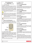
Operating Instructions
This document must be framed and mounted
in view adjacent to the FACP.
for the
DS9400 Series Fire Alarm
Control/Communicators
Local Service Representative
Name ________________________________
Address ______________________________
_____________________________________
Phone _______________________________
Understanding the Built-in Keypad
The keypad built-in to the control/communicator is an alpha-numeric LCD keypad. It has a two line by 16 character
display to provide information on various control panel functions. In most instances, the top line of the display
provides general system status information, while the second line describes specific devices that may be relevant
to the current system status. When keys are being pressed, the display usually shows the current action on the top
line, while displaying rotating menu choices on the second line. A built-in sounder is used to annunciate keystroke
entries and as an interior warning device.
The green Power LED is on when AC power is present,
and flashes when the unit is operating from battery power.
Power
Alarm
The red Alarm LED illuminates whenever the system has
registered an alarm and has not been reset.
Trouble
Silenced
The yellow Trouble LED is lit whenever the system has
detected a problem with its wiring or internal circuitry. It
remains on even when the trouble sounder has been
silenced, turning off only when the underlying trouble
condition has been corrected. The trouble LED flashes
while programming mode is active.
The yellow Silenced LED illuminates when an alarm or
trouble condition has been manually silenced by the user.
It turns off when the condition that was silenced is corrected.
The Drill key is used to activate the notification appliance
circuits manually.
The Disable key allows the system to disable or re-enable
inputs, notification appliance circuits or relays (outputs),
and the dialer.
The Test key allows one of seven special test modes to
be selected.
The Clear key can be used to delete incorrectly entered
data. While programming, it can be used to exit menus or
exit programming mode entirely.
The Programming key will select the programming mode.
1
2
3
Drill
4
5
6
Disable
7
8
9
Test
*
0
#
Silence
Reset
Clear
Prog
Cmnd
The Silence key quiets the bells/sirens for an alarm or
trouble condition.
The Reset key briefly turns off power to detectors to reset
them and clears any off-normal conditions.
History
The History key allows the record of system events to be
viewed.
The Command key is used to accpt data when in
Programming mode.
Modes of System Operation
Normal Operation: When the system is operating normally, it displays “SYSTEM NORMAL” on the top line of the
display, the Power LED is on steady, and no other LEDs are lit. If the system is programmed to require a PIN, the
second line of the LCD screen will display “ENTER PIN:”, otherwise the control panel will bypass this display and
will show a rotating menu of possible user actions.
Alarm Operation: When an alarm occurs, the top line of the display will show “FIRE ALARM”. This display will
override any other system display. The second line of the display will show the number of the point that is in alarm,
alternating with the programmed description for the affected point. If more than one alarm (or other off-normal
condition) is active, they will be shown on the second line of the display, one after another. The built-in sounder turns
on with a steady tone, and outputs programmed to activate with the current alarm condition(s) will activate.
Trouble Operation: When a trouble condition occurs (e.g. wiring for a point is cut, AC power fails, etc.), the
sounder will activate briefly, every 10 seconds. The Trouble LED will light and the top line of the display will show
“SYSTEM TROUBLE”. The second line of the display will identify the specific problem.
Detection Systems, Inc., 130 Perinton Parkway,
Fairport, New York, USA 14450-9199
(585) 223-4060 • (888) 289-0096 • Fax: (585) 223-9180
Copyright © 2001 Detection Systems, Inc.
DS9400 Operating Instructions
P/N: 35841D 9/01
Page 2