1
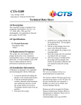
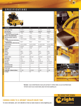
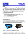
VROC™
(Viscometer/
Rheometer-on-a-Chip)
User’s Manual
1
2
Table of Contents
1.
2.
3.
4.
5.
6.
7.
8.
9.
10.
11.
12.
Unpacking
Precautions
Hardware Setup
Sample Loading
Loading the Syringe on the Pump
Chip to the Syringe Connection
Removing Air Bubbles
Orientation of the Chip
Flow Path Cleaning
Software Setup
VROC_SP_TRAN Program
VROC_RateSweep Program
Appendix I – Front Panel Functions
Appendix II – Guidelines for VROCTM Cleaning
Appendix III – Ordering VROCTM chip and Syringe
4
6
7
8
9
10
10
12
12
13
13
19
24
26
26
3
1. Unpacking
Check the package for any missing components.
Control Box
DC power supply for
the control box –
110 V only
RS232 cable for the
control box
Connector for the control box
and VROC chip interface
VROC chip
4
Syringe pump
USB-to-Serial port converter (2)
Power cord for
the syringe pump
RS232 cable for the
syringe pump
Software CD
5
2. Precautions
CAUTION:
1. Always use the provided software package with the VROC™
chip for any testing and cleaning. The programs have build-in
safety features that prevent pressure from overloading the
chip.
2. Always clean the chip thoroughly after each application and
before storing the chip. Please refer to section nine for cleaning procedures.
3. Particles larger than 10um should be filtered to avoid clogging.
4. Do not spill or allow any liquids inside of the enclosure of
VROC™ chip. It should be kept dry at all times. Note that
the O-rings are not sealed to the enclosure nor the fittings, so
they do not prevent leakage.
5. Keep the inside of the tubes and the flow channel of the chip
wet at all times. Drying could cause irreversible damages to
the chip if the chip is not thoroughly clean.
6. Always leave the tubes connected with the chip. Removing
the tubes exposes the sensor area inside the chip and may
cause damage or clogging.
7. Do not tighten fittings unless they are loose. Over tightening
may damage the chip.
8. Do not apply too much bending force to the Teflon TFA tube.
6
3. Hardware Setup
a. Control Box: Rear panel connection
Rear panel
Connect RS232 connector and DC power.
RS232 DC power
The other end of the RS232 connector
is connected to the computer.
b. Control Box: Front panel connection
Front panel
On/Off Switch
Connector to chip
Align the circular connector by gently pressing the plug of the circular connector against the receptacle, and rotating the plug until a soft click sound
is heard. Then pull the spring loaded silver rim back while pushing the plug
into the receptacle. Finally, release the rim to lock the connector in place.
7
c. Connection to the chip
Plug in the connector to the chip.
d. RS232 connection to the pump
Connect the phone jack
type (TTL) connector of
the Pump-RS232 to the
“IN” port on the back
panel of the syringe
pump. The other end of
the serial port connector
is connected to the computer.
e. Turn on the power for the control box and the syringe pump.
4. Sample Loading
Recommended procedure for loading sample into the syringe
Use the plastic needle (included) to load the sample solution into the syringe. Air bubbles can be generated during sample loading. Remove
them as much as possible by tapping the syringe gently with the needle
pointing upward and pushing a small amount of sample solution out.
Air bubbles can be trapped inside the flow channel of the chip, causing non
-linear pressure profiles due to distorted flow fields. They will also delay
the response time and be a source of error in viscosity measurement as the
bubble is compressed when pumping starts.
8
Troubleshooting to remove trapped air:
When air bubbles are trapped inside the flow channel, usually higher viscosity
samples can be used to remove them. For example, air trapped during water
injection can easily be removed with isopropyl alcohol, which is twice as viscous as water.
To effectively remove all the air bubbles, please refer to section 7.
5. Loading the Syringe on the Pump
Note: Do not connect the syringe to the VROC chip before this step.
a. First unlock the drive nut knob as shown in the photo.
Drive nut knob
Unlocked
position
Pusher block
syringe plunger
b. Load the syringe onto the syringe pump.
c. Slide the pusher block along the guide rods until the block presses
firmly against the syringe plunger. Rotate the knob to lock the drive
nut. Any slight gap between the pusher block and the syringe plunger
could lead to a longer time for a steady state for viscosity measurement. To ensure the intimate contact between the pusher block and the
syringe plunger, press both buttons of Run/Stop button and ➔ and
hold for a very short duration. (Before pressing these two buttons,
make sure that VROC chip is not connected to the syringe.) Please refer
to the User’s Manual of the pump (page 8) for loading the syringe in
detail.
9
6. Chip to Syringe Connection
Remove the plastic needle from the syringe and connect the flat-bottom
fitting from the chip to the syringe. Finger tightening is sufficient. Note:
Do not connect the chip until the syringe is loaded on the pump. (Step 5)
Connection to a syringe
Sold separately
Minimize tubing length by positioning the chip at the same level as the
syringe. (See above figure.)
7. Removing Air Bubbles with a Switching
Valve (Optional but Recommended)
After loading the sample into the syringe, connect the tubes to a switching valve as illustrated in the picture below. Two different tubes are
supplied with the valve: one with fittings on both ends (Tube 1), and the
other with only one fitting (Tube 2). First, connect the black fitting of
Tube 1 to the valve, and then connect the beige/grey fitting to the syringe. Second, connect the black fitting of Tube 2 to the valve. Lastly,
connect the beige/grey fitting from the chip to the third port of the
valve as illustrated.
Arrange the position of the switch on the valve as illustrated in the picture below and operate the pump manually (please refer to the user’s
manual of the pump) to dispense a small portion of the test liquid to the
waste. This procedure effectively removes air bubbles inside the syringe and the tube.
Caution: Do not operate the pump manually when the valve is connecting the syringe to the chip.
10
To Chip
To Syringe
(Tube 1)
To Waste
(Tube 2)
Position of the switch indicates a flow path from the syringe to the waste.
After removing the air bubbles, arrange the position of the switch valve as
illustrated in the picture below to measure the viscosity.
To Chip
To Syringe
(Tube 1)
To Waste
(Tube 2)
Position of the switch indicates a flow path from the syringe to the chip.
11
8. Orientation of the Chip
The inlet and outlet are recommended to be placed horizontally at the
same level.
Configuration
9. Cleaning the Chip after Usage
Always use the provided software package with the VROC™ chip for any
testing and cleaning.
Users should be aware that drying of a sample solution inside the chip after a prolonged period of inactivity carries a high risk of permanently
clogging the chip, preventing normal fluidic flow inside the chip.
To avoid clogging of the chip, it is important that the user cleans the chip
with the appropriate solvent to remove sample solution after usage. The
recommended procedure consists of the following steps: (1) Connect a solvent-filled syringe to the chip. (2) Very slowly infuse about 100ul of solvent to remove majority of the sample solution out of the chip. (flow rate
should not exceed the maximum flow rate used during measurement). (3)
Increase the flow rate and clean the chip as many times as necessary depending on the sample solution. (4) Finally, test the chip with a known sample for viscosity to verify that the chip is clean. Please see Appendix I for
more on the suggested cleaning procedure.
If clogging persists, do not attempt to force a flow as it may cause permanent damage to the chip. If there is any signs of clogging, please contact
the manufacture for a possible solution.
12
10. Software Setup
a.
b.
c.
d.
e.
Create a folder in the C drive in your computer and make a copy of
all the programs, drivers, and the two sensor files that come with your
software installation CD.
VROC_SP_TRANS: This program measures the viscosity at the specific
shear rate defined by the user. It only works with a specific pump,
supplied by the manufacturer.
VROC_RateSweep: This program measures the viscosities at multiple
shear rates defined by the user, within a single test run. It only works
with a specific pump, supplied by the manufacturer.
LVRunTimeEng: LabView program driver. Install the program.
NI-VISA: Serial ports driver. Install the program.
11. VROC_SP_TRAN Program
Type in values for the controls.
Initialization: Select this button to initialize the system.
STOP: Pressing this button will stop the ongoing measurement.
Sample ID: If this field is empty, user will be prompted to enter the ID of
the sample while the program is running.
Viscosity Range (cP): Estimated viscosity range of the test sample. This
value is used to pre-calculate the maximum flow rate and, correspondingly,
gives a warning to the user if the flow rate exceeds the maximum value.
Estimated high-end values of the viscosity of the test sample should be
entered as accurately as possible to minimize the potential damage to
the chip.
Baud Rate: Baud rate of the serial port. Its value should be larger than
57600.
Sensor Port: Serial port for the communication of the VROC™ control box
(COM1 or COMX). Available port can be found in the start/control
panel/system/hardware/device manager/ports. Baud rate of the available port can also be set at this location.
13
Pump Port: Serial port for the communication of the pump.
Sensor ID: User will be prompted to select the sensor file after the program starts. The serial number is located on the back of the VROC™. Each
chip comes with its own sensor files (calibration files), which need to be
loaded onto the program for accurate viscosity measurements. The sensor
file only needs to be loaded once onto the program until user switches to a
different chip. Click the “New Sensor?” button before the next run for a
new sensor chip. There are two sensor files created for two different temperature ranges. The file with a suffix LT (for example, 7VB1100040_LT)
is for the lower temperature range (18 °C ~ 35 °C) whereas the file with a
suffix HT (for example, 7VB1100040_HT) is for higher temperature range
(35 °C ~ 50 °C).
Syringe Diameter (mm): For the syringes supplied by the manufacturer,
choosing the size of the syringe from the drop-down menu will automatically input the diameter. For a custom syringe, enter the diameter by
choosing “custom” from the drop-down menu and enter the value in the
Custom Dia. field.
Sample Volume (µ
µl): Enter the available sample volume for the measurement before the measurement starts. The program will automatically update the available volume after each measurement. This value should be
entered accurately in the beginning to prevent damage to the syringe.
Maximum Pressure (Pa): Displays the maximum pressure range of the
sensor. The program’s build-in safety features monitor the leading sensor
and prevent pressure from overloading the sensor. The green light next to
the Maximum Pressure textbox turns red when the leading sensor experiences a pressure higher than its maximum pressure rating. Beyond this
point, should the pressure continue to rise, the program will automatically
stop to prevent potential damage to the chip.
14
Flow Rate (µ
µl/min ): Enter the pumping flow rate in µl/min. The pump will
be set for the specified flow rate. If this value exceeds the maximum value
calculated using the estimated viscosity, the user will be prompted to lower
the flow rate only once.
Shear rate (s-1 ): Shear rate can be selected instead of the flow rate from
the drop-down menu. Flow rate is determined using the shear rate.
Measu. Time (sec): Enter the total duration of measurement. In addition,
there is a small ripple effect associated with the pumping system. In order
to remove this ripple effect, it is recommended that enough measurement
time be allocated. If the entered measurement time is lower than the required time, the user will be prompted to increase the time only once.
Number to Ave: Number of sample data to average in order to reduce
the random noise. The extent of the noise is inversely proportional to the
square root of the number of average. Therefore, the larger the number
to average is, the smaller the noise will be.
Sampling Time (ms): Sampling time in milliseconds. This is the interval
between measurements. Recommended minimum sampling time is 15 ms.
# of LS Pitch: A lead screw based pump exhibits a small periodic pulsation, which could be large enough at low shear (flow) rates. In order to
maximize the measurement accuracy, the software calculates a period of
the pulsation at each flow rate and averages the measured values accordingly. If averaging over multiple lead screw pitch is desired, then type in
desired number. One lead screw pitch is sufficient in most applications.
Displays
Pumping Rate (µ
µl/min): Displays the actual pumping flow rate in µl/
min.
Delivered Volume: Displays the delivered volume in µl.
Number of Data Points: Displays the total number of data points for
the measurement.
Total Number of Averaged Data: Displays the total number of averaged data points.
Shear Rate (1/s): Displays an apparent shear rate value, assuming
the test solution is Newtonian. For non-Newtonian, the WeissenbergRabinowitsch correction is applied (See note A).
Pressure Drop (Pa/mm): Displays the pressure drop measured by the
sensors.
15
Signal for Ave. (sec): Period of one pitch of the lead screw in seconds.
Pressure vs. Positions: Displays measured pressures at different locations. The curve should be linear at least on average to measure a
meaningful viscosity. The slope of the curve is the Pressure drop.
Temperature (oC): Displays the temperature of the board and the
sensor. Certain types of chips may not have the sensor temperature
included, and it will show a constant temperature, e.g. 25C or 23C.
16
Shear Stress (Pa): Displays the wall shear stress measured in Pa.
Viscosity (Pa-s): Displays the apparent viscosity measured with time scale
(seconds). In order to obtain “non-Newtonian” viscosity, rigorous Weissenberg-Rabinowitsch correction should be applied (see note A). With the
VROC_RateSweep program, the correction can be performed selectively.
Data and Report Saving: At the end of execution, user will be prompted
for data and report saving. In the prompt, the location of temporary report file in html will be disclosed and the same report will be printed to a
default printer. Click OK to save a copy of the files and print.
17
The saved data has the following information:
VROC-VROCW24D3I_3st
Sensor ID
8/30/2006
Date
6:04 PM
Number of Data For Averaging: 25
Flow Rate (ml/min): 0.050000
Time (s)
Board
Temp (oC)
Sensor
Temp (oC)
2.025 mm
(Pa)
4.525 mm
(Pa)
8.325 mm
(Pa)
3.75E-01
2.15E+01
2.16E+01
-2.34E+00
1.09E+01
1.21E+01
Apparent
Shear
Rate (1/s)
2.67E+03
Shear
Stress (pa)
Apparent
Viscosity
(Pa-s)
-2.61E-02
-9.79E06
7.50E-01
2.15E+01
2.6E+01
2.08E+01
2.82E+01
1.76E+01
2.67E+03
8.67E-03
3.25E-06
1.13E+00
2.15E+01
2.16E+01
2.08E+01
5.12E+01
1.06E+00
2.67E+03
4.87E-02
1.83E-05
1.50E+00
2.15E+01
2.16E+01
2.08E+01
5.17E+00
1.76E+01
2.67E+03
2.58E-03
9.68E-07
.
Note A: Weissenberg-Rabinowitsch correction.
Ra ( Newtonian wall shear rate) =
6Q
wh 2
Rwall (corrected wall shear rate) =
Ra
d ln Ra
× [2 +
]
3
d ln τ w
Q is the flow rate, w the width of the channel, h the depth of the flow channel, and τw the measured wall shear stress. In order to apply the correction, a data set of Ra and τw are needed. VROC_RateSweep is designed
to measure the data set and do the correction at the end of the measurement. Caution: The more accurate the collected data set, the more accurate
the correction will be. If data is outside of the measurable range, the correction can be erroneous. If the correction is erroneous, it is recommended
to do the procedure manually.
18
12. VROC_RateSweep Program
The VROC_RateSweep program measures the viscosities at multiple shear
rates defined by the user, within a single test run. The program automatically scans all the inputs (shear rate, number of data points, sensor information, available volumes) to guide a user in the best use of the VROC™.
Enter the values for the controls.
STOP: Pressing this button will stop the ongoing measurement.
Sample ID: If this field is empty, user will be prompted to enter the ID of
the sample while the program is running.
The user can select Newtonian or non-Newtonian before the program runs.
If non-Newtonian is selected, Weissenberg-Rabinowitsch correction is applied automatically at the end of the measurement. At the end of the
measurement, the user will be prompted again for the correction.
Viscosity Range (cP): Estimated viscosity range of the test sample. This
value is used to pre-calculate the maximum flow rate and, correspondingly,
gives a warning to the user if the flow rate exceeds the maximum value.
Estimated high-end values of the viscosity of the test sample should be
entered as accurately as possible to minimize the potential damage to
the chip.
Sensor Port: Serial port for the communication of the VROC™ control box
(COM1 or COMX). Available port can be found in the start/control
panel/system/hardware/device manager/ports. Baud rate of the available port can also be set at this location.
Baud Rate: Baud rate of the serial port. Its value should be greater than
57600.
Sensor ID: User will be prompted to select the sensor file after the program starts. The serial number is located on the back of the VROC™. Each
chip comes with its own sensor files (calibration files), which need to be
loaded onto the program for accurate viscosity measurements. The sensor
file only needs to be loaded once onto the program until user switches to a
different chip. Click the “New Sensor?” button before the next run for a
new sensor chip.
Pump Port: Serial port for the communication of the pump.
19
Syringe Diameter (mm): For the syringes supplied by the manufacturer,
choosing the size of the syringe from the drop-down menu will automatically input the diameter. For a custom syringe, enter the diameter by
choosing “custom” from the drop-down menu and enter the value in the
Custom Dia. field.
Sample Volume (µ
µl): Enter the available sample volume for the measurement before the measurement starts. The program will automatically update the available volume after each measurement. This value should be
entered accurately in the beginning to prevent damage to the syringe.
Maximum Pressure (Pa): Displays the maximum pressure range of the
sensor. The program’s build-in safety features monitor the leading sensor
and prevent pressure from overloading the sensor. The green light next to
the Maximum Pressure textbox turns red when the leading sensor experiences a pressure higher than its maximum pressure rating. Beyond this
point, should the pressure continue to rise, the program will automatically
stop to prevent potential damage to the chip.
Sampling Time (ms): Sampling time in milliseconds. This is the interval
between measurements. Recommended minimum sampling time is 15 ms.
Flow Rate with Unit: Displays the flow rate with proper units.
Dispensed Volume: Displays dispensed volume in µl. The dispensed volume will be updated after each measurement.
Available Volume: Displays available volume in µl. The available volume
will be updated after each measurement.
20
Rate Screening
This feature helps user to set the program so that the program precalculates if the input flow rate (or shear rate) is either too small or too
large for reliable data. The calculation is based on the user input of
the maximum sample viscosity. This feature can be turned off if the
protocol is well established. Otherwise, it should be turned on.
New Protocol: When this button is on (green), the user will be prompted to
save the measurement protocol at the end of the measurement. The file
will have the extension _____.ptc.
When this menu is selected, user inputs flow rate, measurement time, waiting time on the screen panel.
When retrieve protocol is selected, the user can use existing protocol for
the measurement. This feature is useful for repeated measurements.
Flow Rate (µ
µl/min): Enter the flow rates at which viscosity needs to be
measured. One can also choose shear rate (1/s) using the drop-down
menu.
Measurement Time (sec): Enter the desired duration of measurement of
viscosity. It is recommended that enough measurement time be allocated.
Or select the time using the drop-down menu. If “preset” is selected, the
minimum measurement time calculated based on the lead screw pitch will
be used for the optimum measurement. “preset” is recommended for most
applications.
Waiting Time (sec): The time needed to reach a steady state for a viscosity measurement. Because of a slight compressibility, and small yet finite
“dead volume,” reaching the steady state viscosity may take time. It could
take a few seconds or more than 10 seconds, depending on the pumping
flow rate and viscosity of the sample. If the sample has air voids and the
void volume is significant, it could take much longer.
21
The user is encouraged to use the VROC_SP_TRANS to find out the necessary waiting time for each sample. Clicking on the button will display available “pre-set” times and “custom” times for user input value.
Display results
Pressure vs. Positions: Displays measured pressures at different locations.
The curve should be linear at least on average to measure a meaningful
viscosity. All the pressure profiles at different shear rates are displayed in
the graph above.
Results: Displays the results including board temperature (T Board), sensor
temperature (T sensor, some sensors do not have this feature), pressure
drop (DP Pa/min), flow rate (µl/min), shear rate (S.R. 1/s), shear stress
(S.S. pa), viscosity (Pa-s), true shear rate (corrected shear rate), and true
viscosity (corrected viscosity).
22
Viscosity vs. Shear Rate: Displays all of the results of the viscosity measured at all the shear rates.
Data and Report Saving: At the end of execution, user will be prompted
for data and report saving. In the prompt, the location of temporary report file in html will be disclosed and the same report will be printed to a
default printer. Click OK to save a copy of the files and print.
Note: Using the VROC_SP program, completely fill the VROC chip flow
channel with test sample (no bubbles inside the channel) before making the
baseline measurement for the evaluation test. This is a very important step
to ensure accurate baseline measurements. A partially filled channel will
give an erroneous reading of baseline. If there is liquid inside the chip,
make sure that at least 80 µl of sample is pumped to the chip to replace
the liquid with the test sample. If there is enough sample, 150 µl elution
volume is needed.
Appendix I
Extra Functions on Front Panel
File Tab
• Open – open program
• Close – close program
• Close all – close program
• Page setup – printer set up: choose printer and page set up for printing
• Print windows-print front panel
• VI properties – general : location of the program
Exit – close the
Edit
• Reinitialize to default-change all the control settings back to default
values
23
Appendix I
Extra Functions on Front Panel
File Tab
• Open – open program
• Close – close program
• Close all – close program
• Page setup – printer set up: choose printer and page set up for printing
• Print windows-print front panel
• VI properties – general : location of the program
• Exit – close program
Edit Tab
• Reinitialize to default-change all the control settings back to default
values
24
Operate Tab
• Print at completion – print front panel upon completion of a run.
• Log at completion – control values in the front panel will be logged
upon completion of a run
• Data Logging
◊ Log – log the control values. If not logged, a prompt for a
new file name will appear.
◊ Retrieve – the following screen below will be displayed.
Select the desired log file to retrieve. Control values saved in
the same log file are saved in sequence and can be retrieved.
◊ Change log file binding — change to different log file name
◊ Clear the log file binding — clear the binding to the log file
created.
Retrieve is no longer available after the binding is cleared.
Tools Tab (newer program only Rate Sweep 3.1.5 and VPv7.1)
• Security
• Domain account manager
25
Appendix II
GUIDELINES FOR
VROC™ Cleaning
Low viscosity
(Below 100cp)
Medium viscosity
High viscosity
(Above 1000cp)
5cc flushing
10 to 20cc flushing
20-50cc flushing
• Low viscosity inks
• Low concentration
polymer solutions
• Various solvents
• Lubricants
• Shampoo
• Medium concentration polymer
solutions
• Paints
• High concentration
polymer solutions
Appendix III
Ordering VROC Chip and Syringe
The VROC™ is offered in three chip specifications (A, B, C) to maximize the
viscosity range for precise measurements. The VROC—B chip is our general use viscometer. The specialty VROC chips are as follows:
A chips
(A02, A05, A10)
Low viscosity
(0.2 cP—200 cP)
• Small sample volume
• Low shear rate
B chips
(B02, B05, B10)
Medium viscosity
(0.2 cP—2,000 cP)
• General use viscometer
• Sufficient amount of sample for low viscosity samples
C chips
(C02, C05, C10,
C20)
High viscosity
(0.2 cP—10,000 cP)
• low viscosity samples—
high shear, sufficient sample required
• High viscosity samples
26
1.
2.
3.
4.
Estimate the viscosity range of the test sample.
Determine the amount of available sample volume.
Determine any special requirement on high shear rate.
Refer to the Shear rate and Flow rate tables on the following pages
and find the chip and syringes that meet your application.
For example:
To test ink at high shear rate:
1. ink viscosity: ~ 4 cP.
2. Amount of sample available: unlimited.
3. Shear rate requirement: 1.0x10E5 1/s.
4. Refer to the Shear rate and Flow rate tables and find for the proper
chip based on viscosity, shear rate requirement, and sample amount.
(Sometimes, more than one chip can meet the requirement.) Both A
and B chips cannot meet the requirement for high shear rate. Now,
looking at the C Chips, both C05 and C10 chips are capable of reaching the required shear rate. For the C05 chip, maximum flow rate and
minimum flow rate are 8.73cc per min and 0.087cc per min, respectively. The recommended syringe size is 10cc for the maximum flow
rate range. For the C10 chip, maximum flow rate and minimum flow
rate are 68.7cc per min and 0.687cc per min, respectively. The recommended syringe size is 50cc. The 50cc syringe should be used with
a HP (High Pressure) pump.
C05:
Shear rate, 1/s
Flow rate, µl/min
Recommended Syringe
Size
Viscosity
(mPa*s)
Min
Max
Min
Max
Min
Max
4
1.16E+03
1.16E+05
8.73E+01
8.73E+03
1cc
10cc
4
2.28E+03
2.28E+05
6.87E+02
6.87E+04
10cc
50cc
C10:
Note:
Minimum flow rate is 1.07µl/min with 100uL syringes
Maximum flow rate is 31890µl/min with 25cc syringes
Maximum flow rate is 75000µl/min with 50cc syringes (only with HP pump)
27
VROC A-02
Full Scale Pressure, Pa
Flow Channel Gap, um
Flow Channel Width, mm
1.00E+04
20
3.02
Shear rate, 1/s
Flow rate, µl/min
Recommended Syringe Size
Viscosity
(mPa*s)
0.2
Min
Max
Min
Max
Min
Max
4.67E+02
4.67E+04
5.64E+00
5.64E+02
100ul
500ul
0.4
2.34E+02
2.34E+04
2.82E+00
2.82E+02
100ul
250ul
0.6
1.56E+02
1.56E+04
1.88E+00
1.88E+02
100ul
250ul
0.8
1.17E+02
1.17E+04
1.41E+00
1.41E+02
100ul
100ul
1
9.35E+01
9.35E+03
1.13E+00
1.13E+02
100ul
100ul
2
4.67E+01
4.67E+03
5.64E-01
5.64E+01
-
100ul
4
2.34E+01
2.34E+03
2.82E-01
2.82E+01
-
100ul
6
1.56E+01
1.56E+03
1.88E-01
1.88E+01
-
100ul
8
1.17E+01
1.17E+03
1.41E-01
1.41E+01
-
100ul
10
9.35E+00
9.35E+02
1.13E-01
1.13E+01
-
100ul
20
4.67E+00
4.67E+02
5.64E-02
5.64E+00
-
100ul
40
2.34E+00
2.34E+02
2.82E-02
2.82E+00
-
100ul
60
1.56E+00
1.56E+02
1.88E-02
1.88E+00
-
100ul
80
1.17E+00
1.17E+02
1.41E-02
1.41E+00
-
100ul
100
9.35E-01
9.35E+01
1.13E-02
1.13E+00
-
-
200
4.67E-01
4.67E+01
5.64E-03
5.64E-01
-
-
400
2.34E-01
2.34E+01
2.82E-03
2.82E-01
-
-
600
1.56E-01
1.56E+01
1.88E-03
1.88E-01
-
-
800
1.17E-01
1.17E+01
1.41E-03
1.41E-01
-
-
1000
9.35E-02
9.35E+00
1.13E-03
1.13E-01
-
-
2000
4.67E-02
4.67E+00
5.64E-04
5.64E-02
-
-
4000
2.34E-02
2.34E+00
2.82E-04
2.82E-02
-
-
6000
1.56E-02
1.56E+00
1.88E-04
1.88E-02
-
-
8000
1.17E-02
1.17E+00
1.41E-04
1.41E-02
-
-
10000
9.35E-03
9.35E-01
1.13E-04
1.13E-02
-
-
gray = values smaller than min flow rate
orange = values larger than max flow rate with 1 syringe configuration
blue = values can be achieved by using HP pump and/or 50cc syringe
28
VROC A-05
Full Scale Pressure, Pa
Flow Channel Gap, um
Flow Channel Width, mm
1.00E+04
50
3.02
Shear rate, 1/s
Flow rate, µl/min
Recommended Syringe Size
Viscosity
(mPa*s)
Min
Max
Min
Max
Min
Max
0.2
1.16E+03
1.16E+05
8.73E+01
8.73E+03
1cc
10cc
0.4
5.78E+02
5.78E+04
4.37E+01
4.37E+03
1cc
5cc
0.6
3.86E+02
3.86E+04
2.91E+01
2.91E+03
500ul
2.5cc
0.8
2.89E+02
2.89E+04
2.18E+01
2.18E+03
500ul
2.5cc
1
2.31E+02
2.31E+04
1.75E+01
1.75E+03
250ul
1cc
2
1.16E+02
1.16E+04
8.73E+00
8.73E+02
100ul
1cc
4
5.78E+01
5.78E+03
4.37E+00
4.37E+02
100ul
500ul
6
3.86E+01
3.86E+03
2.91E+00
2.91E+02
100ul
250ul
8
2.89E+01
2.89E+03
2.18E+00
2.18E+02
100ul
250ul
10
2.31E+01
2.31E+03
1.75E+00
1.75E+02
100ul
100ul
20
1.16E+01
1.16E+03
8.73E-01
8.73E+01
-
100ul
40
5.78E+00
5.78E+02
4.37E-01
4.37E+01
-
100ul
60
3.86E+00
3.86E+02
2.91E-01
2.91E+01
-
100ul
80
2.89E+00
2.89E+02
2.18E-01
2.18E+01
-
100ul
100
2.31E+00
2.31E+02
1.75E-01
1.75E+01
-
100ul
200
1.16E+00
1.16E+02
8.73E-02
8.73E+00
-
100ul
400
5.78E-01
5.78E+01
4.37E-02
4.37E+00
-
100ul
600
3.86E-01
3.86E+01
2.91E-02
2.91E+00
-
100ul
800
2.89E-01
2.89E+01
2.18E-02
2.18E+00
-
100ul
1000
2.31E-01
2.31E+01
1.75E-02
1.75E+00
-
-
2000
1.16E-01
1.16E+01
8.73E-03
8.73E-01
-
-
4000
5.78E-02
5.78E+00
4.37E-03
4.37E-01
-
-
6000
3.86E-02
3.86E+00
2.91E-03
2.91E-01
-
-
8000
2.89E-02
2.89E+00
2.18E-03
2.18E-01
-
-
10000
2.31E-02
2.31E+00
1.75E-03
1.75E-01
-
-
29
VROC A-10
Full Scale Pressure, Pa
Flow Channel Gap, um
Flow Channel Width, mm
1.00E+04
100
3.02
Shear rate, 1/s
Flow rate, µl/min
Recommended Syringe Size
Viscosity
(mPa*s)
Min
Max
Min
Max
Min
Max
0.2
2.28E+03
2.28E+05
6.87E+02
6.87E+04
10cc
50cc
0.4
1.14E+03
1.14E+05
3.44E+02
3.44E+04
5cc
25cc
0.6
7.59E+02
7.59E+04
2.29E+02
2.29E+04
5cc
25cc
0.8
5.69E+02
5.69E+04
1.72E+02
1.72E+04
2.5cc
10cc
1
4.55E+02
4.55E+04
1.37E+02
1.37E+04
2.5cc
10cc
2
2.28E+02
2.28E+04
6.87E+01
6.87E+03
1cc
5cc
4
1.14E+02
1.14E+04
3.44E+01
3.44E+03
500ul
2.5cc
6
7.59E+01
7.59E+03
2.29E+01
2.29E+03
500ul
2.5cc
8
5.69E+01
5.69E+03
1.72E+01
1.72E+03
250ul
1cc
10
4.55E+01
4.55E+03
1.37E+01
1.37E+03
250ul
1cc
20
2.28E+01
2.28E+03
6.87E+00
6.87E+02
100ul
500ul
40
1.14E+01
1.14E+03
3.44E+00
3.44E+02
100ul
250ul
60
7.59E+00
7.59E+02
2.29E+00
2.29E+02
100ul
250ul
80
5.69E+00
5.69E+02
1.72E+00
1.72E+02
100ul
100ul
100
4.55E+00
4.55E+02
1.37E+00
1.37E+02
100ul
100ul
200
2.28E+00
2.28E+02
6.87E-01
6.87E+01
-
100ul
400
1.14E+00
1.14E+02
3.44E-01
3.44E+01
-
100ul
600
7.59E-01
7.59E+01
2.29E-01
2.29E+01
-
100ul
800
5.69E-01
5.69E+01
1.72E-01
1.72E+01
-
100ul
1000
4.55E-01
4.55E+01
1.37E-01
1.37E+01
-
100ul
2000
2.28E-01
2.28E+01
6.87E-02
6.87E+00
-
100ul
4000
1.14E-01
1.14E+01
3.44E-02
3.44E+00
-
100ul
6000
7.59E-02
7.59E+00
2.29E-02
2.29E+00
-
100ul
8000
5.69E-02
5.69E+00
1.72E-02
1.72E+00
-
100ul
10000
4.55E-02
4.55E+00
1.37E-02
1.37E+00
-
-
30
VROC B-02
Full Scale Pressure, Pa
Flow Channel Gap, um
Flow Channel Width, mm
4.00E+04
20
3.02
Shear rate, 1/s
Flow rate, µl/min
Recommended Syringe Size
Viscosity
(mPa*s)
Min
Max
Min
Max
Min
Max
0.2
1.87E+03
1.87E+05
2.26E+01
2.26E+03
500ul
2.5cc
0.4
9.35E+02
9.35E+04
1.13E+01
1.13E+03
250ul
1cc
0.6
6.23E+02
6.23E+04
7.53E+00
7.53E+02
100ul
1cc
0.8
4.67E+02
4.67E+04
5.64E+00
5.64E+02
100ul
500ul
1
3.74E+02
3.74E+04
4.52E+00
4.52E+02
100ul
500ul
2
1.87E+02
1.87E+04
2.26E+00
2.26E+02
100ul
250ul
4
9.35E+01
9.35E+03
1.13E+00
1.13E+02
100ul
100ul
6
6.23E+01
6.23E+03
7.53E-01
7.53E+01
-
100ul
8
4.67E+01
4.67E+03
5.64E-01
5.64E+01
-
100ul
10
3.74E+01
3.74E+03
4.52E-01
4.52E+01
-
100ul
20
1.87E+01
1.87E+03
2.26E-01
2.26E+01
-
100ul
40
9.35E+00
9.35E+02
1.13E-01
1.13E+01
-
100ul
60
6.23E+00
6.23E+02
7.53E-02
7.53E+00
-
100ul
80
4.67E+00
4.67E+02
5.64E-02
5.64E+00
-
100ul
100
3.74E+00
3.74E+02
4.52E-02
4.52E+00
-
100ul
200
1.87E+00
1.87E+02
2.26E-02
2.26E+00
-
-
400
9.35E-01
9.35E+01
1.13E-02
1.13E+00
-
-
600
6.23E-01
6.23E+01
7.53E-03
7.53E-01
-
-
800
4.67E-01
4.67E+01
5.64E-03
5.64E-01
-
-
1000
3.74E-01
3.74E+01
4.52E-03
4.52E-01
-
-
2000
1.87E-01
1.87E+01
2.26E-03
2.26E-01
-
-
4000
9.35E-02
9.35E+00
1.13E-03
1.13E-01
-
-
6000
6.23E-02
6.23E+00
7.53E-04
7.53E-02
-
-
8000
4.67E-02
4.67E+00
5.64E-04
5.64E-02
-
-
10000
3.74E-02
3.74E+00
4.52E-04
4.52E-02
-
-
31
VROC B-05
Full Scale Pressure, Pa
Flow Channel Gap, um
Flow Channel Width, mm
4.00E+04
50
3.02
Shear rate, 1/s
Flow rate, µl/min
Recommended Syringe Size
Viscosity
(mPa*s)
Min
Max
Min
Max
Min
Max
0.2
4.63E+03
4.63E+05
3.49E+02
3.49E+04
5cc
25cc
0.4
2.31E+03
2.31E+05
1.75E+02
1.75E+04
2.5cc
10cc
0.6
1.54E+03
1.54E+05
1.16E+02
1.16E+04
2.5cc
10cc
0.8
1.16E+03
1.16E+05
8.73E+01
8.73E+03
1cc
10cc
1
9.25E+02
9.25E+04
6.99E+01
6.99E+03
1cc
5cc
2
4.63E+02
4.63E+04
3.49E+01
3.49E+03
500ul
2.5cc
4
2.31E+02
2.31E+04
1.75E+01
1.75E+03
250ul
1cc
6
1.54E+02
1.54E+04
1.16E+01
1.16E+03
250ul
1cc
8
1.16E+02
1.16E+04
8.73E+00
8.73E+02
100ul
1cc
10
9.25E+01
9.25E+03
6.99E+00
6.99E+02
100ul
500ul
20
4.63E+01
4.63E+03
3.49E+00
3.49E+02
100ul
250ul
40
2.31E+01
2.31E+03
1.75E+00
1.75E+02
100ul
100ul
60
1.54E+01
1.54E+03
1.16E+00
1.16E+02
100ul
100ul
80
1.16E+01
1.16E+03
8.73E-01
8.73E+01
-
100ul
100
9.25E+00
9.25E+02
6.99E-01
6.99E+01
-
100ul
200
4.63E+00
4.63E+02
3.49E-01
3.49E+01
-
100ul
400
2.31E+00
2.31E+02
1.75E-01
1.75E+01
-
100ul
600
1.54E+00
1.54E+02
1.16E-01
1.16E+01
-
100ul
800
1.16E+00
1.16E+02
8.73E-02
8.73E+00
-
100ul
1000
9.25E-01
9.25E+01
6.99E-02
6.99E+00
-
100ul
2000
4.63E-01
4.63E+01
3.49E-02
3.49E+00
-
100ul
4000
2.31E-01
2.31E+01
1.75E-02
1.75E+00
-
100ul
6000
1.54E-01
1.54E+01
1.16E-02
1.16E+00
-
-
8000
1.16E-01
1.16E+01
8.73E-03
8.73E-01
-
-
10000
9.25E-02
9.25E+00
6.99E-03
6.99E-01
-
-
32
VROC B-10
Full Scale Pressure, Pa
Flow Channel Gap, um
Flow Channel Width, mm
4.00E+04
100
3.02
Shear rate, 1/s
Flow rate, µl/min
Recommended Syringe Size
Viscosity
(mPa*s)
Min
Max
Min
Max
Min
Max
0.2
9.11E+03
9.11E+05
2.75E+03
2.75E+05
50cc
-
0.4
4.55E+03
4.55E+05
1.37E+03
1.37E+05
25cc
-
0.6
3.04E+03
3.04E+05
9.17E+02
9.17E+04
25cc
-
0.8
2.28E+03
2.28E+05
6.87E+02
6.87E+04
10cc
50cc
1
1.82E+03
1.82E+05
5.50E+02
5.50E+04
10cc
50cc
2
9.11E+02
9.11E+04
2.75E+02
2.75E+04
5cc
25cc
4
4.55E+02
4.55E+04
1.37E+02
1.37E+04
2.5cc
10cc
6
3.04E+02
3.04E+04
9.17E+01
9.17E+03
2.5cc
10cc
8
2.28E+02
2.28E+04
6.87E+01
6.87E+03
1cc
5cc
10
1.82E+02
1.82E+04
5.50E+01
5.50E+03
1cc
5cc
20
9.11E+01
9.11E+03
2.75E+01
2.75E+03
500ul
2.5cc
40
4.55E+01
4.55E+03
1.37E+01
1.37E+03
250ul
1cc
60
3.04E+01
3.04E+03
9.17E+00
9.17E+02
250ul
1cc
80
2.28E+01
2.28E+03
6.87E+00
6.87E+02
100ul
500ul
100
1.82E+01
1.82E+03
5.50E+00
5.50E+02
100ul
500ul
200
9.11E+00
9.11E+02
2.75E+00
2.75E+02
100ul
250ul
400
4.55E+00
4.55E+02
1.37E+00
1.37E+02
100ul
100ul
600
3.04E+00
3.04E+02
9.17E-01
9.17E+01
-
100ul
800
2.28E+00
2.28E+02
6.87E-01
6.87E+01
-
100ul
1000
1.82E+00
1.82E+02
5.50E-01
5.50E+01
-
100ul
2000
9.11E-01
9.11E+01
2.75E-01
2.75E+01
-
100ul
4000
4.55E-01
4.55E+01
1.37E-01
1.37E+01
-
100ul
6000
3.04E-01
3.04E+01
9.17E-02
9.17E+00
-
100ul
8000
2.28E-01
2.28E+01
6.87E-02
6.87E+00
-
100ul
10000
1.82E-01
1.82E+01
5.50E-02
5.50E+00
-
100ul
33
VROC B-20
Full Scale Pressure, Pa
Flow Channel Gap, um
Flow Channel Width, mm
4.00E+04
200
3.02
Shear rate, 1/s
Flow rate, µl/min
Recommended Syringe Size
Viscosity
(mPa*s)
Min
Max
Min
Max
Min
Max
0.2
1.76E+04
1.76E+06
2.13E+04
2.13E+06
50cc
-
0.4
8.82E+03
8.82E+05
1.07E+04
1.07E+06
50cc
-
0.6
5.88E+03
5.88E+05
7.11E+03
7.11E+05
50cc
-
0.8
4.41E+03
4.41E+05
5.33E+03
5.33E+05
50cc
-
1
3.53E+03
3.53E+05
4.26E+03
4.26E+05
50cc
-
2
1.76E+03
1.76E+05
2.13E+03
2.13E+05
50cc
-
4
8.82E+02
8.82E+04
1.07E+03
1.07E+05
25cc
-
6
5.88E+02
5.88E+04
7.11E+02
7.11E+04
10cc
50cc
8
4.41E+02
4.41E+04
5.33E+02
5.33E+04
10cc
50cc
10
3.53E+02
3.53E+04
4.26E+02
4.26E+04
10cc
50cc
20
1.76E+02
1.76E+04
2.13E+02
2.13E+04
5cc
25cc
40
8.82E+01
8.82E+03
1.07E+02
1.07E+04
2.5cc
10cc
60
5.88E+01
5.88E+03
7.11E+01
7.11E+03
1cc
5cc
80
4.41E+01
4.41E+03
5.33E+01
5.33E+03
1cc
5cc
100
3.53E+01
3.53E+03
4.26E+01
4.26E+03
1cc
5cc
200
1.76E+01
1.76E+03
2.13E+01
2.13E+03
500ul
2.5cc
400
8.82E+00
8.82E+02
1.07E+01
1.07E+03
250ul
1cc
600
5.88E+00
5.88E+02
7.11E+00
7.11E+02
100ul
500ul
800
4.41E+00
4.41E+02
5.33E+00
5.33E+02
100ul
500ul
1000
3.53E+00
3.53E+02
4.26E+00
4.26E+02
100ul
500ul
2000
1.76E+00
1.76E+02
2.13E+00
2.13E+02
100ul
250ul
4000
8.82E-01
8.82E+01
1.07E+00
1.07E+02
100ul
100ul
6000
5.88E-01
5.88E+01
7.11E-01
7.11E+01
-
100ul
8000
4.41E-01
4.41E+01
5.33E-01
5.33E+01
-
100ul
10000
3.53E-01
3.53E+01
4.26E-01
4.26E+01
-
100ul
34
VROC C-02
Full Scale Pressure, Pa
Flow Channel Gap, um
Flow Channel Width, mm
2.00E+05
20
3.02
Shear rate, 1/s
Flow rate, µl/min
Recommended Syringe Size
Viscosity
(mPa*s)
Min
Max
Min
Max
Min
Max
0.2
9.35E+03
9.35E+05
1.13E+02
1.13E+04
2.5cc
10cc
0.4
4.67E+03
4.67E+05
5.64E+01
5.64E+03
1cc
5cc
0.6
3.12E+03
3.12E+05
3.76E+01
3.76E+03
1cc
5cc
0.8
2.34E+03
2.34E+05
2.82E+01
2.82E+03
500ul
2.5cc
1
1.87E+03
1.87E+05
2.26E+01
2.26E+03
500ul
2.5cc
2
9.35E+02
9.35E+04
1.13E+01
1.13E+03
250ul
1cc
4
4.67E+02
4.67E+04
5.64E+00
5.64E+02
100ul
500ul
6
3.12E+02
3.12E+04
3.76E+00
3.76E+02
100ul
500ul
8
2.34E+02
2.34E+04
2.82E+00
2.82E+02
100ul
250ul
10
1.87E+02
1.87E+04
2.26E+00
2.26E+02
100ul
250ul
20
9.35E+01
9.35E+03
1.13E+00
1.13E+02
100ul
100ul
40
4.67E+01
4.67E+03
5.64E-01
5.64E+01
-
100ul
60
3.12E+01
3.12E+03
3.76E-01
3.76E+01
-
100ul
80
2.34E+01
2.34E+03
2.82E-01
2.82E+01
-
100ul
100
1.87E+01
1.87E+03
2.26E-01
2.26E+01
-
100ul
200
9.35E+00
9.35E+02
1.13E-01
1.13E+01
-
100ul
400
4.67E+00
4.67E+02
5.64E-02
5.64E+00
-
100ul
600
3.12E+00
3.12E+02
3.76E-02
3.76E+00
-
100ul
800
2.34E+00
2.34E+02
2.82E-02
2.82E+00
-
100ul
1000
1.87E+00
1.87E+02
2.26E-02
2.26E+00
-
100ul
2000
9.35E-01
9.35E+01
1.13E-02
1.13E+00
-
-
4000
4.67E-01
4.67E+01
5.64E-03
5.64E-01
-
-
6000
3.12E-01
3.12E+01
3.76E-03
3.76E-01
-
-
8000
2.34E-01
2.34E+01
2.82E-03
2.82E-01
-
-
10000
1.87E-01
1.87E+01
2.26E-03
2.26E-01
-
-
35
VROC C-05
Full Scale Pressure, Pa
Flow Channel Gap, um
Flow Channel Width, mm
2.00E+05
50
3.02
Shear rate, 1/s
Flow rate, µl/min
Recommended Syringe Size
Viscosity
(mPa*s)
Min
Max
Min
Max
Min
Max
0.2
2.31E+04
2.31E+06
1.75E+03
1.75E+05
25cc
-
0.4
1.16E+04
1.16E+06
8.73E+02
8.73E+04
10cc
-
0.6
7.71E+03
7.71E+05
5.82E+02
5.82E+04
10cc
50cc
0.8
5.78E+03
5.78E+05
4.37E+02
4.37E+04
10cc
50cc
1
4.63E+03
4.63E+05
3.49E+02
3.49E+04
5cc
25cc
2
2.31E+03
2.31E+05
1.75E+02
1.75E+04
2.5cc
10cc
4
1.16E+03
1.16E+05
8.73E+01
8.73E+03
1cc
10cc
6
7.71E+02
7.71E+04
5.82E+01
5.82E+03
1cc
5cc
8
5.78E+02
5.78E+04
4.37E+01
4.37E+03
1cc
5cc
10
4.63E+02
4.63E+04
3.49E+01
3.49E+03
500ul
2.5cc
20
2.31E+02
2.31E+04
1.75E+01
1.75E+03
250ul
1cc
40
1.16E+02
1.16E+04
8.73E+00
8.73E+02
100ul
1cc
60
7.71E+01
7.71E+03
5.82E+00
5.82E+02
100ul
500ul
80
5.78E+01
5.78E+03
4.37E+00
4.37E+02
100ul
500ul
100
4.63E+01
4.63E+03
3.49E+00
3.49E+02
100ul
250ul
200
2.31E+01
2.31E+03
1.75E+00
1.75E+02
100ul
100ul
400
1.16E+01
1.16E+03
8.73E-01
8.73E+01
-
100ul
600
7.71E+00
7.71E+02
5.82E-01
5.82E+01
-
100ul
800
5.78E+00
5.78E+02
4.37E-01
4.37E+01
-
100ul
1000
4.63E+00
4.63E+02
3.49E-01
3.49E+01
-
100ul
2000
2.31E+00
2.31E+02
1.75E-01
1.75E+01
-
100ul
4000
1.16E+00
1.16E+02
8.73E-02
8.73E+00
-
100ul
6000
7.71E-01
7.71E+01
5.82E-02
5.82E+00
-
100ul
8000
5.78E-01
5.78E+01
4.37E-02
4.37E+00
-
100ul
10000
4.63E-01
4.63E+01
3.49E-02
3.49E+00
-
100ul
36
VROC C-10
Full Scale Pressure, Pa
Flow Channel Gap, um
Flow Channel Width, mm
2.00E+05
100
3.02
Shear rate, 1/s
Flow rate, µl/min
Recommended Syringe Size
Viscosity
(mPa*s)
Min
Max
Min
Max
Min
Max
0.2
4.55E+04
4.55E+06
1.37E+04
1.37E+06
50cc
-
0.4
2.28E+04
2.28E+06
6.87E+03
6.87E+05
50cc
-
0.6
1.52E+04
1.52E+06
4.58E+03
4.58E+05
50cc
-
0.8
1.14E+04
1.14E+06
3.44E+03
3.44E+05
50cc
-
1
9.11E+03
9.11E+05
2.75E+03
2.75E+05
50cc
-
2
4.55E+03
4.55E+05
1.37E+03
1.37E+05
25cc
-
4
2.28E+03
2.28E+05
6.87E+02
6.87E+04
10cc
50cc
6
1.52E+03
1.52E+05
4.58E+02
4.58E+04
10cc
50cc
8
1.14E+03
1.14E+05
3.44E+02
3.44E+04
5cc
25cc
10
9.11E+02
9.11E+04
2.75E+02
2.75E+04
5cc
25cc
20
4.55E+02
4.55E+04
1.37E+02
1.37E+04
2.5cc
10cc
40
2.28E+02
2.28E+04
6.87E+01
6.87E+03
1cc
5cc
60
1.52E+02
1.52E+04
4.58E+01
4.58E+03
1cc
5cc
80
1.14E+02
1.14E+04
3.44E+01
3.44E+03
500ul
2.5cc
100
9.11E+01
9.11E+03
2.75E+01
2.75E+03
500ul
2.5cc
200
4.55E+01
4.55E+03
1.37E+01
1.37E+03
250ul
1cc
400
2.28E+01
2.28E+03
6.87E+00
6.87E+02
100ul
500ul
600
1.52E+01
1.52E+03
4.58E+00
4.58E+02
100ul
500ul
800
1.14E+01
1.14E+03
3.44E+00
3.44E+02
100ul
250ul
1000
9.11E+00
9.11E+02
2.75E+00
2.75E+02
100ul
250ul
2000
4.55E+00
4.55E+02
1.37E+00
1.37E+02
100ul
100ul
4000
2.28E+00
2.28E+02
6.87E-01
6.87E+01
-
100ul
6000
1.52E+00
1.52E+02
4.58E-01
4.58E+01
-
100ul
8000
1.14E+00
1.14E+02
3.44E-01
3.44E+01
-
100ul
10000
9.11E-01
9.11E+01
2.75E-01
2.75E+01
-
100ul
37
VROC C-20
Full Scale Pressure, Pa
Flow Channel Gap, um
Flow Channel Width, mm
2.00E+05
200
3.02
Shear rate, 1/s
Flow rate, µl/min
Recommended Syringe Size
Viscosity
(mPa*s)
Min
Max
Min
Max
Min
Max
0.2
8.82E+04
8.82E+06
1.07E+05
1.07E+07
50cc
-
0.4
4.41E+04
4.41E+06
5.33E+04
5.33E+06
50cc
-
0.6
2.94E+04
2.94E+06
3.55E+04
3.55E+06
50cc
-
0.8
2.21E+04
2.21E+06
2.66E+04
2.66E+06
50cc
-
1
1.76E+04
1.76E+06
2.13E+04
2.13E+06
50cc
-
2
8.82E+03
8.82E+05
1.07E+04
1.07E+06
50cc
-
4
4.41E+03
4.41E+05
5.33E+03
5.33E+05
50cc
-
6
2.94E+03
2.94E+05
3.55E+03
3.55E+05
50cc
-
8
2.21E+03
2.21E+05
2.66E+03
2.66E+05
50cc
-
10
1.76E+03
1.76E+05
2.13E+03
2.13E+05
50cc
-
20
8.82E+02
8.82E+04
1.07E+03
1.07E+05
25cc
-
40
4.41E+02
4.41E+04
5.33E+02
5.33E+04
10cc
50cc
60
2.94E+02
2.94E+04
3.55E+02
3.55E+04
5cc
25cc
80
2.21E+02
2.21E+04
2.66E+02
2.66E+04
5cc
25cc
100
1.76E+02
1.76E+04
2.13E+02
2.13E+04
5cc
25cc
200
8.82E+01
8.82E+03
1.07E+02
1.07E+04
2.5cc
10cc
400
4.41E+01
4.41E+03
5.33E+01
5.33E+03
1cc
5cc
600
2.94E+01
2.94E+03
3.55E+01
3.55E+03
500ul
2.5cc
800
2.21E+01
2.21E+03
2.66E+01
2.66E+03
500ul
2.5cc
1000
1.76E+01
1.76E+03
2.13E+01
2.13E+03
500ul
2.5cc
2000
8.82E+00
8.82E+02
1.07E+01
1.07E+03
250ul
1cc
4000
4.41E+00
4.41E+02
5.33E+00
5.33E+02
100ul
500ul
6000
2.94E+00
2.94E+02
3.55E+00
3.55E+02
100ul
250ul
8000
2.21E+00
2.21E+02
2.66E+00
2.66E+02
100ul
250ul
10000
1.76E+00
1.76E+02
2.13E+00
2.13E+02
100ul
250ul
38
VROC C-30
Full Scale Pressure, Pa
Flow Channel Gap, um
Flow Channel Width, mm
2.00E+05
300
3.02
Shear rate, 1/s
Flow rate, µl/min
Recommended Syringe Size
Viscosity
(mPa*s)
Min
Max
Min
Max
Min
Max
0.2
1.28E+05
1.28E+07
3.49E+05
3.49E+07
50cc
-
0.4
6.42E+04
6.42E+06
1.74E+05
1.74E+07
50cc
-
0.6
4.28E+04
4.28E+06
1.16E+05
1.16E+07
50cc
-
0.8
3.21E+04
3.21E+06
8.72E+04
8.72E+06
50cc
-
1
2.57E+04
2.57E+06
6.98E+04
6.98E+06
50cc
-
2
1.28E+04
1.28E+06
3.49E+04
3.49E+06
50cc
-
4
6.42E+03
6.42E+05
1.74E+04
1.74E+06
50cc
-
6
4.28E+03
4.28E+05
1.16E+04
1.16E+06
50cc
-
8
3.21E+03
3.21E+05
8.72E+03
8.72E+05
50cc
-
10
2.57E+03
2.57E+05
6.98E+03
6.98E+05
50cc
-
20
1.28E+03
1.28E+05
3.49E+03
3.49E+05
50cc
-
40
6.42E+02
6.42E+04
1.74E+03
1.74E+05
25cc
-
60
4.28E+02
4.28E+04
1.16E+03
1.16E+05
25cc
-
80
3.21E+02
3.21E+04
8.72E+02
8.72E+04
10cc
-
100
2.57E+02
2.57E+04
6.98E+02
6.98E+04
10cc
50cc
200
1.28E+02
1.28E+04
3.49E+02
3.49E+04
5cc
25cc
400
6.42E+01
6.42E+03
1.74E+02
1.74E+04
2.5cc
10cc
600
4.28E+01
4.28E+03
1.16E+02
1.16E+04
2.5cc
10cc
800
3.21E+01
3.21E+03
8.72E+01
8.72E+03
1cc
10cc
1000
2.57E+01
2.57E+03
6.98E+01
6.98E+03
1cc
5cc
2000
1.28E+01
1.28E+03
3.49E+01
3.49E+03
500ul
2.5cc
4000
6.42E+00
6.42E+02
1.74E+01
1.74E+03
250ul
1cc
6000
4.28E+00
4.28E+02
1.16E+01
1.16E+03
250ul
1cc
8000
3.21E+00
3.21E+02
8.72E+00
8.72E+02
100ul
1cc
10000
2.57E+00
2.57E+02
6.98E+00
6.98E+02
100ul
500ul
39
40