1
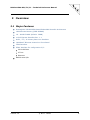
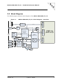
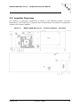
NPCIe-8560-8E1/T1/J1 – Technical Reference Manual
NPCIe-8560-8E1/T1/J1
Telecom PCIe Module
Technical Reference Manual V1.2
HW Revision 1.0
NPCIe-8560-8E1/T1/J1 – Technical Reference Manual
The NPCIe-8560-8E1/T1/J1 has been designed by:
N.A.T. GmbH
Konrad-Zuse-Platz 9
D-53227 Bonn
Phone: +49 / 228 / 965 864 - 0
Fax: +49 /228 / 965 864 - 10
Internet: http://www.nateurope.com
Version 1.2
© N.A.T. GmbH
2
NPCIe-8560-8E1/T1/J1 – Technical Reference Manual
Disclaimer
The following documentation, compiled by N.A.T. GmbH (henceforth called N.A.T.),
represents the current status of the product´s development. The documentation is
updated on a regular basis. Any changes which might ensue, including those necessitated
by updated specifications, are considered in the latest version of this documentation.
N.A.T. is under no obligation to notify any person, organization, or institution of such
changes or to make these changes public in any other way.
We must caution you, that this publication could include technical inaccuracies or
typographical errors.
N.A.T. offers no warranty, either expressed or implied, for the contents of this
documentation or for the product described therein, including but not limited to the
warranties of merchantability or the fitness of the product for any specific purpose.
In no event will N.A.T. be liable for any loss of data or for errors in data utilization or
processing resulting from the use of this product or the documentation. In particular,
N.A.T. will not be responsible for any direct or indirect damages (including lost profits,
lost savings, delays or interruptions in the flow of business activities, including but not
limited to, special, incidental, consequential, or other similar damages) arising out of the
use of or inability to use this product or the associated documentation, even if N.A.T. or
any authorized N.A.T. representative has been advised of the possibility of such
damages.
The use of registered names, trademarks, etc. in this publication does not imply, even in
the absence of a specific statement, that such names are exempt from the relevant
protective laws and regulations (patent laws, trade mark laws, etc.) and therefore free
for general use. In no case does N.A.T. guarantee that the information given in this
documentation is free of such third-party rights.
Neither this documentation nor any part thereof may be copied, translated, or reduced to
any electronic medium or machine form without the prior written consent from N.A.T.
GmbH.
This product (and the associated documentation) is governed by the N.A.T. General
Conditions and Terms of Delivery and Payment.
Note:
The release of the Hardware Manual is related to a certain HW board
revision given in the document title. For HW revisions earlier than the one
given in the document title please contact N.A.T. for the corresponding older
Hardware Manual release.
Version 1.2
© N.A.T. GmbH
3
NPCIe-8560-8E1/T1/J1 – Technical Reference Manual
Table of Contents
TABLE OF CONTENTS .......................................................................................... 4
LIST OF TABLES .................................................................................................. 5
LIST OF FIGURES ................................................................................................ 5
CONVENTIONS .................................................................................................... 6
1
INTRODUCTION ........................................................................................... 7
2
OVERVIEW ................................................................................................... 8
2.1
2.2
2.3
3
MAJOR FEATURES ........................................................................................ 8
BLOCK DIAGRAM ......................................................................................... 9
LOCATION OVERVIEW ..................................................................................10
BOARD FEATURES ...................................................................................... 11
3.1
CPU ......................................................................................................11
3.1.1
Processor Core .................................................................................11
3.1.2
Processor – Integrated I/O ................................................................11
3.2
MEMORY ..................................................................................................12
3.2.1
DDR SDRAM ....................................................................................12
3.2.2
FLASH .............................................................................................12
3.3
PCI EXPRESS INTERFACE ..............................................................................12
3.4
E1/T1/J1 LINE INTERFACES ..........................................................................12
3.5
ETHERNET ................................................................................................12
3.6
PTMC INTERFACE .......................................................................................13
3.7
ITDM .....................................................................................................13
3.8
I2C DEVICES.............................................................................................13
4
HARDWARE ................................................................................................ 14
4.1
FRONT PANEL AND LEDS ..............................................................................14
4.2
CONNECTORS AND SWITCHES .........................................................................15
4.2.1
P1: PCI Express Connector ................................................................16
4.2.2
S1: Ethernet Connector .....................................................................16
4.2.3
S3: ISDN Connector .........................................................................17
4.2.4
JP1: Lattice Programming Port ...........................................................18
4.2.5
JP2: BDM and JTAG Connector ...........................................................18
4.2.6
P11/P12: PMC Connectors .................................................................19
4.2.7
P13: PMC Connector .........................................................................20
4.2.8
P14: PMC Connector – Configuration 2/3 .............................................21
4.2.9
S2: RS232 Connector ........................................................................22
4.2.10
DIP SW1: Flash Half Select / PCIe Bridge Direction ...............................22
4.2.10.1
DIP SW1: Switch 1 – Boot FLASH Select Switch .............................22
4.2.10.2
DIP SW1: Switch 2 – PCIe Bridge Direction Switch .........................23
4.2.11
LF1: Write-Protect-Pin – Solder Field...................................................23
4.2.12
LF2: Voltage Source – Solder Field .....................................................23
5
NPCIE-8560-8E1/T1/J1 PROGRAMMING NOTES ........................................ 24
6
BOARD SPECIFICATION ............................................................................. 25
Version 1.2
© N.A.T. GmbH
4
NPCIe-8560-8E1/T1/J1 – Technical Reference Manual
7
INSTALLATION .......................................................................................... 26
7.1
SAFETY NOTE ............................................................................................26
7.2
INSTALLATION PREREQUISITES AND REQUIREMENTS ...............................................27
7.2.1
Requirements ..................................................................................27
7.2.2
Power supply ...................................................................................27
7.2.3
Automatic Power Up..........................................................................27
7.2.4
Thermal Considerations .....................................................................27
7.3
STATEMENT ON ENVIRONMENTAL PROTECTION .....................................................28
7.3.1
Compliance to RoHS Directive ............................................................28
7.3.2
Compliance to WEEE Directive ............................................................28
7.3.3
Compliance to CE Directive ................................................................29
7.3.4
Product Safety .................................................................................29
8
KNOWN BUGS / RESTRICTIONS ................................................................. 30
APPENDIX A: REFERENCE DOCUMENTATION .................................................... 31
APPENDIX B: DOCUMENT’S HISTORY ............................................................... 32
List of Tables
Table
Table
Table
Table
Table
Table
Table
Table
Table
Table
Table
Table
Table
Table
Table
Table
Table
1:
2:
3:
4:
5:
6:
7:
8:
9:
10:
11:
12:
13:
14:
15:
16:
17:
List of used abbreviations ...................................................................... 6
P1: PCIe Connector – Pin Assignment .....................................................16
S1: Ethernet Connector – Pin Assignment ...............................................16
S3a: ISDN Connector – Pin Assignment ..................................................17
S3b: ISDN Connector – Pin Assignment ..................................................17
S3c: ISDN Connector – Pin Assignment ..................................................17
S3d: ISDN Connector – Pin Assignment ..................................................17
JP1: Lattice Programming Port – Pin Assignment .....................................18
JP2: BDM and JTAG Connector – Pin Assignment .....................................18
P11/P12: PMC Connectors – Pin Assignment............................................19
P13: PMC Connector – Pin Assignment ...................................................20
P14: PMC Connector – Configuration 2/3 – Pin Assignment .......................21
S2: RS232 Connector – Pin Assignment ..................................................22
DIP SW1: Pin Assignment - Overview .....................................................22
DIP SW1: Switch 1 – Boot Flash Select – Pin Assignment ..........................22
DIP SW1: Switch 2 – PCIe Bridge Direction – Pin Assignment ....................23
NPCIe-8560-8E1/T1/J1 – Features .........................................................25
List of Figures
Figure
Figure
Figure
Figure
1:
2:
3:
4:
Version 1.2
NPCIe-8560-8E1/T1/J1– Block Diagram - Overview .................................. 9
NPCIe-8560-8E1/T1/J1 – Location diagram – Overview ............................10
NPCIe-8560-8E1/T1/J1 – Front Panel View ..............................................14
NPCIe-8560-8E1/T1/J1 – Connector and Switch location – Overview ..........15
© N.A.T. GmbH
5
NPCIe-8560-8E1/T1/J1 – Technical Reference Manual
Conventions
If not otherwise specified, addresses and memory maps are written in hexadecimal
notation, identified by 0x.
The following table gives a list of the abbreviations used in this document.
Table 1:
List of used abbreviations
Abbreviation
Description
b
B
CPLD
CPU
DDR
DMA
DRAM
E1
FLASH
FPGA
iTDM
J1
LIU
MPC8560
PCIe
PCI-X
PowerQUICC III
RAM
ROM
SCbus
SCC
SCSA
SDRAM
SMC
T1
TDM
TSI
TSA
Bit, binary
Byte
Complex Programmable Logic Device
Central Processing Unit
Dual Data Rate
Direct Memory Access
Dynamic RAM
2.048 Mbit G.703 Interface
Reprogrammable ROM
Field Programmable Gate Array
internal TDM
1,544 Mbit G.703 Interface (Japan)
Line Interface Unit
Embedded Processor from Freescale
PCI Express
Extended PCI
MPC8560
Random Access Memory
Read Only Memory
Time-Slot Interchange Bus of the SCSA, subset of H.110 bus
Serial Communication Controller of the MPC8560
Signal Computing System Architecture
Synchronous Dynamic RAM
Serial Communication Controller of the MPC8560
1,544 Mbit G.703 Interface (USA)
Time Division Multiplex
Time Slot Interchange
Time Slot Assigner
Version 1.2
© N.A.T. GmbH
6
NPCIe-8560-8E1/T1/J1 – Technical Reference Manual
1 Introduction
The NPCIe-8560-8E1/T1/J1 is a high performance standard height, full length PCI
Express x1 add-in card. The NPCIe-8560-8E1/T1/J1 is providing access to E1/T1/J1
interfaces combined with the functionality of a PMC carrier board. It is intended to be
used with standard PMC or PTMC modules in a standard PC with PCI Express extension
slots.
Version 1.2
© N.A.T. GmbH
7
NPCIe-8560-8E1/T1/J1 – Technical Reference Manual
2 Overview
2.1 Major Features
PowerQUICC III MPC8560 based Embedded PowerPC Architecture
128 MB main Memory (DDR SDRAM)
16 – 64 MB FLASH (default: 32MB)
x1 PCI Express Interface Rev. 1.1
8x E1 / T1 / J1 Primary Rate Line Interface
1000BaseT Ethernet channel on Front Panel
iTDM Interface
PTMC Interface for configuration 2/3:
32 bit PCI bus
CT bus
Ethernet
RS232 serial I/O
Version 1.2
© N.A.T. GmbH
8
NPCIe-8560-8E1/T1/J1 – Technical Reference Manual
2.2 Block Diagram
The following figure shows a block diagram of the NPCIe-8560-8E1/T1/J1.
PCIe to
PCI bridge
PCIe x1
GbE
PHY
1GbE Ethernet
PTMC connectors J1 and J2
NPCIe-8560-8E1/T1/J1– Block Diagram - Overview
PCI 32 bit
Temp.
Sensor
GMII
RTC
I2C
MPC8560
833MHz
RMII (PTMC CFG 2) or
MIDI (PTMC CFG5)
CPU DDR bus
64bit
PowerQUICC3TM
eTSEC1
Face
Plate
128-256MB
DDR
SDRAM
333MHz
GbE
FPGA
Lattice ECP3
PTMC connector J3 (CFG 2)
or (design option)
PTMC connector J4 (CFG 5)
PCIe x1 Connector
Figure 1:
PTMC site
(CFG 2 or 5)
16-64MB
FLASH
Local Bus
CT Bus (H.110)
E1/T1/J1 1/2
E1/T1/J1 3/4
E1/T1/J1 5/6
Maxim
Octal
E1 Framer
DS26518
TDM Bus
PLL
Zarlink
ZL30100
PTMC connector J3
RS232
Console
Reference clock signals
E1/T1/J1 7/8
SPI
SPI
M
U
X
SPI
FLASH
Version 1.2
© N.A.T. GmbH
9
NPCIe-8560-8E1/T1/J1 – Technical Reference Manual
2.3 Location Overview
The position of important components is shown in the following location overview.
Depending on the board type it might be that the board does not include all components
named in the location diagram.
Figure 2:
Version 1.2
NPCIe-8560-8E1/T1/J1 – Location diagram – Overview
© N.A.T. GmbH
10
NPCIe-8560-8E1/T1/J1 – Technical Reference Manual
3 Board Features
The NPCIe-8560-8E1/T1/J1 can be divided into a number of functional blocks, which
are described in the following paragraphs.
3.1 CPU
3.1.1 Processor Core
The MPC8560 PowerQUICC III™ is a versatile communications processor that
integrates on one chip a high-performance PowerPC™ RISC microprocessor
running at 833MHz, a very flexible system integration unit and many
communications peripheral controllers that can be used in a variety of
applications, particularly in communications and networking systems.
The core is an embedded variant of the PowerPC e500™ core with 32 Kbytes of
instruction cache and 32 Kbytes of data cache. To this primary cache adds 256
Kbytes of Level 2 cache. The system interface unit (SIU) consists of a flexible
memory controller that interfaces to almost any user-defined memory system and
many other peripherals making this device a complete system on a chip.
3.1.2 Processor – Integrated I/O
The MPC8560 PowerQUICC III™ integrates a switch fabric and 2 10/100/1000 MB
MACs, which support various standard protocols.
The communications processor module (CPM) includes four serial communications
controllers (SCCs), with the addition of three high-performance communication
channels that support new emerging protocols (for example, 155 Mbps ATM and
Fast Ethernet). The CPM frequency may be set up to 333 MHz.
The MPC8560 features dedicated hardware that can handle up to 256 full-duplex,
time-division-multiplexed logical channels, as well as DMA functionality executing
memory to memory and memory to I/O transfers.
Furthermore the MPC8560 integrates a 64 bit PCI / PCI-X interface, and a 4channel DMA controller.
Version 1.2
© N.A.T. GmbH
11
NPCIe-8560-8E1/T1/J1 – Technical Reference Manual
3.2 Memory
3.2.1 DDR SDRAM
The onboard DDR SDRAM memory is 64 bit wide; its size is 128MB. The interface
to the DDR SDRAM is implemented in the MPC8560. By programming several
registers the DDR RAM controller can be adapted to different RAM architectures.
3.2.2 FLASH
The NPCIe-8560-8E1/T1/J1 provides a 16 bit wide FLASH PROM with a
capacity of 16 - 64MB (assembly option, default: 32MB). This memory is
connected to the demultiplexed upper 16 data bits D0 – 15 and to the latched
address lines. Demultiplexing of the local address/data bus of the CPU, as well as
address latching, is performed by an FPGA. The FLASH PROM can be programmed
either by the CPU (by appropriate software or through the BDM port) or by a PCI
bus master.
3.3 PCI Express Interface
The NPCIe-8560-8E1/T1/J1 includes a x1 PCI Express interface which is implemented
in a PEX8111 PCI-X to PCIe bridge (PLX). The PCI Express interface is connected directly
to the PCI Express connector whereas the PCI interface is connected to the MPC8560 CPU
and the PMC connector.
The PCIe bridge may receive its reference clock either from the PCIe connector or from a
local 100 MHz oscillator circuitry; the clock source is programmable.
3.4 E1/T1/J1 Line Interfaces
The NPCIe-8560-8E1/T1/J1 carries a Maxim DS26518 framer, which implements eight
E1/T1/J1 interfaces. These interfaces connect the framer to the front panel RJ45
connector S3. Timing and interface characteristics can be set up by software within the
DS26518. The line interfaces conform to EN60950 and G.703 / G.823 (Jitter
Attenuation). The front panel RJ45 connector S3 consists of 4 RJ45 jacks with integrated
LEDs. In order to support 8 E1/T1/J1 interfaces each RJ45 jack carries 2 E1/T1/J1
interfaces. The LEDs are bi-colored and programmable through registers which reside
within the FPGA.
3.5 Ethernet
The NPCIe-8560-8E1/T1/J1 implements a Gigabit Ethernet interface (1000Base-T) at
the front panel that is connected to the onboard FPGA. All other onboard devices are
connected to the same FPGA, which implements a HUB functionality that allows all
devices to access the front interface. The connected devices are the TSEC Ethernet MAC
of the MPC8560 CPU as well as the PMC/PTMC (connected to the FPGA via RMII) and the
iTDM block implemented in the FPGA. (The PMC is only connected via a 100MBit
interface.)
The Broadcom BCM5461 Ethernet PHY is connected to the FPGA via GMII interface. It
connects to the front panel connector S1.
Version 1.2
© N.A.T. GmbH
12
NPCIe-8560-8E1/T1/J1 – Technical Reference Manual
3.6 PTMC Interface
The NPCIe-8560-8E1/T1/J1 implements a CT-Bus (H.110) that connects to the PMC
connector.
3.7 iTDM
The NPCIe-8560-8E1/T1/J1 implements a serial iTDM interface based on Ethernet.
The iTDM Block (implemented in the FPGA) has also access to the Ethernet Hub block.
Therefore the iTDM Block can transfer data through the same physical ports that
connects to the front panel interface or the PTMC.
The iTDM interface conforms to the SFP.0 and SFP.1 specifications.
3.8 I2C Devices
The NPCIe-8560-8E1/T1/J1 features an I²C link which is connected to the MPC8560
I2C interface and to a couple of local devices.
The following devices are connected:
An EEPROM for storage of board-specific information (24C08)
A temperature sensor (LM75) which is located near the MPC8560 CPU to sense the
processor temperature
A real time clock device (DS1339C)
Version 1.2
© N.A.T. GmbH
13
NPCIe-8560-8E1/T1/J1 – Technical Reference Manual
4 Hardware
4.1 Front Panel and LEDs
The following figures shows the LEDs placed on the front panel of the NPCIe-85608E1/T1/J1.
Figure 3:
NPCIe-8560-8E1/T1/J1 – Front Panel View
S1
LED1
S3d
S3c
S3b
S3a
LED2
The NPCIe-8560-8E1/T1/J1 module is equipped with 2 LEDs, which are controlled by
the Ethernet PHY. They are integrated in the RJ45 Ethernet interface jack. LED1 is
showing the link status and LED2 shows the activity.
Please refer to Chapter 4.2 for detailed information about the front panel connectors.
Version 1.2
© N.A.T. GmbH
14
NPCIe-8560-8E1/T1/J1 – Technical Reference Manual
4.2 Connectors and Switches
Figure 4:
NPCIe-8560-8E1/T1/J1 – Connector and Switch location –
Overview
Please refer to the following sub-chapters to look up the connector pin assignment of the
NPCIe-8560-8E1/T1/J1.
Version 1.2
© N.A.T. GmbH
15
NPCIe-8560-8E1/T1/J1 – Technical Reference Manual
4.2.1 P1: PCI Express Connector
P1 is a standard PCIe x1 connector.
Table 2:
P1: PCIe Connector – Pin Assignment
Pin #
Signal
Signal
Pin #
A1
A2
A3
A4
A5
A6
A7
A8
A9
A10
A11
A12
A13
A14
A15
A16
A17
A18
PRSNT1#
+12V
+12V
GND
TCK
TDI
TDO
TMS
+3.3V
+3.3V
/PERST
GND
REFCLK+
REFCLKGND
PERp0
PERn0
GND
+12V
+12V
+12V
GND
SMCLK
SMDAT
GND
+3.3V
TRST#
+3.3Vaux
WAKE#
NC
GND
PETp0
PETn0
GND
PRSNT2#
GND
B1
B2
B3
B4
B5
B6
B7
B8
B9
B10
B11
B12
B13
B14
B15
B16
B17
B18
4.2.2 S1: Ethernet Connector
The following table shows the pin assignment of RJ45-connector S1. This
connector carries the 1000BaseT signals of the Ethernet interface.
Table 3:
S1: Ethernet Connector – Pin Assignment
Pin #
Signal
Signal
Pin #
1
3
5
7
MX0+
MX1+
MX2MX3+
MX0MX2+
MX1MX3-
2
4
6
8
Version 1.2
© N.A.T. GmbH
16
NPCIe-8560-8E1/T1/J1 – Technical Reference Manual
4.2.3 S3: ISDN Connector
The ISDN front panel connectors are 8-pin RJ45 connectors. The 8 E1/T1/J1 line
interfaces are available on the pins of the front panel connectors S3a – S3d; each
connector carries two interfaces. The following tables show the pin assignments.
Table 4:
S3a: ISDN Connector – Pin Assignment
Pin #
Signal
Signal
Pin #
1
3
5
7
RX7+
RX8+
TX7TX8+
RX7TX7+
RX8TX8-
2
4
6
8
Table 5:
S3b: ISDN Connector – Pin Assignment
Pin #
Signal
Signal
Pin #
1
3
5
7
RX5+
RX6+
TX5TX6+
RX5TX5+
RX6TX6-
2
4
6
8
Table 6:
S3c: ISDN Connector – Pin Assignment
Pin #
Signal
Signal
Pin #
1
3
5
7
RX3+
RX4+
TX3TX4+
RX3TX3+
RX4TX4-
2
4
6
8
Table 7:
S3d: ISDN Connector – Pin Assignment
Pin #
Signal
Signal
Pin #
1
3
5
7
RX1+
RX2+
TX1TX2+
RX1TX1+
RX2TX2-
2
4
6
8
Version 1.2
© N.A.T. GmbH
17
NPCIe-8560-8E1/T1/J1 – Technical Reference Manual
4.2.4 JP1: Lattice Programming Port
Connector JP1 connects the JTAG- or programming port of the Lattice FPGA
devices.
Table 8:
JP1: Lattice Programming Port – Pin Assignment
Pin #
Signal
Signal
Pin #
1
3
5
7
9
3.3V
TDI
NC
GND
DONE
TDO
/PROGRAMN
TMS
TCK
INITN
2
4
6
8
10
4.2.5 JP2: BDM and JTAG Connector
The BDM port (also called COP header) can be used for debugging. It is supported
by major debug tool manufacturers.
Table 9:
JP2: BDM and JTAG Connector – Pin Assignment
Pin #
Signal
Signal
Pin #
1
3
5
7
9
11
13
15
TDO
TDI
10K PU to +3.3V
TCK
TMS
/SRESET
/HRESET
/CKSTP_OUT
nc
/TRST
2K PU to+3.3V
/CKSTP_IN
nc
nc
nc
GND
2
4
6
8
10
12
14
16
Version 1.2
© N.A.T. GmbH
18
NPCIe-8560-8E1/T1/J1 – Technical Reference Manual
4.2.6
P11/P12: PMC Connectors
Table 10:
P11/P12: PMC Connectors – Pin Assignment
P11
P12
Pin #
Signal
Signal
Pin #
Pin #
Signal
Signal
Pin #
1
3
5
7
9
11
13
15
17
19
21
23
25
27
29
31
33
35
37
39
41
43
45
47
49
51
53
55
57
59
61
63
TCK
GND
INTB#
NC
INTD#
GND
CLK
GND
REQ#
V(I/O)
AD[28]
AD[25]
GND
AD[22]
AD[19]
V(I/O)
FRAME#
GND
DEVSEL#
GND
PCI-RSVD
PAR
V(I/O)
AD[12]
AD[09]
GND
AD[06]
AD[04]
V(I/O)
AD[02]
AD[00]
GND
-12V
INTA#
INTC#
+5V
PMC-RSVD
NC
GND
GNT#
+5V
AD[31]
AD[27]
GND
C/BE[3]#
AD[21]
+5V
AD[17]
GND
IRDY#
+5V
LOCK#
PMC-RSVD
GND
AD[15]
AD[11]
+5V
C/BE[0]#
AD[05]
GND
AD[03]
AD[01]
+5V
REQ64#
2
4
6
8
10
12
14
16
18
20
22
24
26
28
30
32
34
36
38
40
42
44
46
48
50
52
54
56
58
60
62
64
1
3
5
7
9
11
13
15
17
19
21
23
25
27
29
31
33
35
37
39
41
43
45
47
49
51
53
55
57
59
61
63
+12V
TMS
TDI
GND
PMC-RSVD
NC
RST#
3.3V
PME#
AD[30]
GND
AD[24]
IDSEL
+3.3V
AD[18]
AD[16]
GND
TRDY#
GND
PERR#
+3.3V
C/BE[1]#
AD[14]
M66EN
AD[08]
AD[07]
+3.3V
PMC-RSVD
PMC-RSVD
GND
ACK64#
GND
TRST#
TDO
GND
PMC-RSVD
PMC-RSVD
+3.3V
NC
NC
GND
AD[29]
AD[26]
+3.3V
AD[23]
AD[20]
GND
C/BE[2]#
PMC-RSVD
+3.3V
STOP#
GND
SERR#
GND
AD[13]
AD[10]
+3.3V
PMC-RSVD
PMC-RSVD
GND
PMC-RSVD
PMC-RSVD
+3.3V
PMC-RSVD
2
4
6
8
10
12
14
16
18
20
22
24
26
28
30
32
34
36
38
40
42
44
46
48
50
52
54
56
58
60
62
64
Version 1.2
© N.A.T. GmbH
19
NPCIe-8560-8E1/T1/J1 – Technical Reference Manual
4.2.7 P13: PMC Connector
Table 11:
P13: PMC Connector – Pin Assignment
Pin #
Signal
Signal
Pin #
1
3
5
7
9
11
13
15
17
19
21
23
25
27
29
31
33
35
37
39
41
43
45
47
49
51
53
55
57
59
61
63
MDIO
GND
MDC
RXER
PTID2
PTGNDZ
REFCLK
GND
CT_FA
CT_FB
PTID0
PTGNDZ
CT_C8A
GND
CT_D18
CT_D16
GND
CT_D14
CT_D12
PTENB#
PTGNDZ
CT_C8B
GND
CT_D10
CT_D8
GND
CT_D6
CT_D4
PTID1
CT_D2
CT_D0
GND
GND
STX
SRX
GND
TXD0
TXD1
GND
RXD0
RXD1
GND
TXEN
CAS_DV
GND
CT_D19
CT_D17
GND
NETREF2
USER1Z
GND
USER2Z
NETREF1
GND
CT_D15
CT_D13
CT_D11
CT_D9
CT_D7
GND
CT_D5
CT_D3
GND
CT_D1
2
4
6
8
10
12
14
16
18
20
22
24
26
28
30
32
34
36
38
40
42
44
46
48
50
52
54
56
58
60
62
64
Version 1.2
© N.A.T. GmbH
20
NPCIe-8560-8E1/T1/J1 – Technical Reference Manual
4.2.8 P14: PMC Connector – Configuration 2/3
Table 12:
Pin #
P14: PMC Connector – Configuration 2/3 – Pin Assignment
P14 (Configuration 2)
Signal
Signal
Pin #
1
3
5
7
9
11
13
15
17
19
21
23
25
27
29
31
33
35
37
39
41
43
45
47
49
51
53
55
57
59
61
63
USER
USER
USER
USER
USER
USER
USER
USER
USER
USER
USER
USER
USER
USER
USER
USER
USER
USER
USER
USER
USER
USER
USER
USER
USER
USER
USER
USER
USER
USER
USER
USER
USER
USER
USER
USER
USER
USER
USER
USER
USER
USER
USER
USER
USER
USER
USER
USER
USER
USER
USER
USER
USER
USER
USER
USER
USER
USER
USER
USER
USER
USER
USER
USER
2
4
6
8
10
12
14
16
18
20
22
24
26
28
30
32
34
36
38
40
42
44
46
48
50
52
54
56
58
60
62
64
Pin #
1
3
5
7
9
11
13
15
17
19
21
23
25
27
29
31
33
35
37
39
41
43
45
47
49
51
53
55
57
59
61
63
P14 (Configuration 3)
Signal
Signal
Pin #
TxSOC
GND
TXCLAV
RXADR3
USER
GND
TXREF
GND
TXADR3
TXADR2
USER
GND
TXCLK
GND
TXADR0
TXPRTY
GND
TXD7
TXD6
USER
GND
RXCLK
GND
TXD5
TXD4
GND
+TXD3
TXD2
USER
TXD1
TXD0
GND
GND
RXADR4
TXADR4
GND
GND
RXREF
GND
RXENB#
RXCLAV
GND
TXENB#
RXADR2
GND
TXADR1
RXADR1
GND
RXADR0
RXPRTY
GND
RXD7
RXD6
GND
RXD5
RXD6
GND
RXD3
RXD2
GND
RXD1
RXD0
GND
RxSOC
2
4
6
8
10
12
14
16
18
20
22
24
26
28
30
32
34
36
38
40
42
44
46
48
50
52
54
56
58
60
62
64
For configuration 2 the PTMC Specification does not define a fixed usage for the
PINS marked with USER. These pins are connected to the FPGA on the NPCIe8560-8E1/T1/J1. Please contact NAT if a user defined usage of those pins is
needed!
Version 1.2
© N.A.T. GmbH
21
NPCIe-8560-8E1/T1/J1 – Technical Reference Manual
4.2.9 S2: RS232 Connector
The following table shows the pin assignment of the RS232 interface.
Table 13:
S2: RS232 Connector – Pin Assignment
Pin #
Signal
Signal
Pin #
1
3
5
NC
TxD_SCC1
GND
RxD_SCC1
NC
2
4
Connector S2 is connected to SCC1 of the MPC8560 CPM.
4.2.10 DIP SW1: Flash Half Select / PCIe Bridge Direction
The table below gives an overview of the operating parameters configurable via
DIP SW1. Details are given in the following subchapters.
Table 14:
DIP SW1: Pin Assignment - Overview
Switch #
Function
1
2
FLASH half select
PCIe Bridge Direction
4.2.10.1
DIP SW1: Switch 1 – Boot FLASH Select Switch
By operating Switch 1 of DIP SW1 to ON, the upper half of the Boot FLASH is
selected for booting. If Switch 1 of DIP SW1 is turned to OFF, the lower half of the
Boot FLASH is selected for booting.
Table 15:
DIP SW1: Switch 1 – Boot Flash Select – Pin Assignment
DIP SW1 – Switch 1
Function
Upper FLASH Half
1
2
Lower FLASH Half
1
2
Default:
Switch 1 of DIP SW1 is toggled to OFF, lower half of the Boot FLASH is selected
for booting.
Version 1.2
© N.A.T. GmbH
22
NPCIe-8560-8E1/T1/J1 – Technical Reference Manual
4.2.10.2
DIP SW1: Switch 2 – PCIe Bridge Direction Switch
This switch is used to select the source of the PCIe reference clock. If Switch 2 of
DIP SW1 is turned to ON a local 100MHz reference is chosen. Additionally the PCI
reset from the PEX8112 has no longer impact on the rest of the board. This mode
is intended to be selected when the board is used in a standalone application.
If Switch 2 of DIP SW1 is turned to OFF the external reference clock from the PCIe
connector is taken.
Table 16:
DIP SW1: Switch 2 – PCIe Bridge Direction – Pin Assignment
DIP SW1 – Switch 2
Function
Local 100MHz Clock
1
2
1
2
External Clock from PCIe Connector
Default:
Switch 2 of DIP SW1 is switched to OFF, external clock from PCIe connector
selected
4.2.11 LF1: Write-Protect-Pin – Solder Field
If the solder field LF1 is closed the Write-Protect-Pin (WP-Pin) of the FLASH is
asserted.
Default:
Solder field LF1 is open, FLASH write protection is disabled.
4.2.12 LF2: Voltage Source – Solder Field
Solder field LF2 selects the source of the PMC +3.3VAUX. If the solder field is
closed towards the mark on the PCB “3.3V AUX”, the +3.3V AUX of the PMC is
directly connected to the +3.3VAUX of the PCIe connector. If the solder field is
closed to the other side the +3.3VAUX of the PMC is sourced by the local generated
+3.3V.
Default:
Solder field LF2 is closed towards the mark “3.3V AUX”, the PMC +3.3V AUX is
sourced by the local generated +3.3V.
Version 1.2
© N.A.T. GmbH
23
NPCIe-8560-8E1/T1/J1 – Technical Reference Manual
5 NPCIe-8560-8E1/T1/J1 Programming Notes
TBD
Note:
This chapter will be completed in a later version of the User’s Manual. For the time being,
contact N.A.T. for further assistance on programming.
Version 1.2
© N.A.T. GmbH
24
NPCIe-8560-8E1/T1/J1 – Technical Reference Manual
6 Board Specification
Table 17:
NPCIe-8560-8E1/T1/J1 – Features
Processor
PCI Express Module
Front-I/O
Main Memory
FLASH PROM
Firmware
Power Consumption
(MPC8560 / 833MHz)
Operating Temperature
Storage Temperature
Humidity
Standards compliance
Version 1.2
PowerQUICC III MPC8560 (833MHz) based
Embedded PowerPC Architecture
Standard height, full length PCI Express x1
add-in card (111.15mm x 312.00mm)
5x RJ45 connectors
128MB DDR SDRAM
16 – 64MB FLASH PROM – on board programmable
OK1, LINUX BSP (on request)
12V 2.0A max.
0°C – +65°C with forced cooling
-40°C - +85°C
10% – 90% rh non-condensing
PCI Express Base Specification Rev. 1.1
PCI Express CEM Specification Rev. 1.1
PICMG 2.15 Rev. 1.0
ITU-T G.703 (for E1/T1 Standard)
ITU-T G.823 (Jitter Attenuation)
© N.A.T. GmbH
25
NPCIe-8560-8E1/T1/J1 – Technical Reference Manual
7 Installation
7.1 Safety Note
To ensure proper functioning of the NPCIe-8560-8E1/T1/J1 during its usual lifetime
take the following precautions before handling the board.
CAUTION
Electrostatic discharge and incorrect board installation and uninstallation can damage
circuits or shorten their lifetime.
Before installing or uninstalling the NPCIe-8560-8E1/T1/J1 read this installation
section
Before installing or uninstalling the NPCIe-8560-8E1/T1/J1, read the Installation
Guide and the User’s Manual of the PC/Server main board used, or of the PCIe system
the board will be plugged into.
Before installing or uninstalling the NPCIe-8560-8E1/T1/J1 switch off the power.
Before touching integrated circuits ensure to take all require precautions for handling
electrostatic devices.
Ensure that the NPCIe-8560-8E1/T1/J1 is connected to the main board or to the
PCIe backplane with the connector completely inserted.
When operating the board in areas of strong electromagnetic radiation ensure that the
module
is bolted the front panel or rack
and shielded by closed housing
Version 1.2
© N.A.T. GmbH
26
NPCIe-8560-8E1/T1/J1 – Technical Reference Manual
7.2 Installation Prerequisites and Requirements
IMPORTANT
Before powering up check this section for installation prerequisites and requirements!
7.2.1 Requirements
The installation requires only
an PCIe main board or a PCIe backplane for connecting the NPCIe-85608E1/T1/J1
7.2.2 Power supply
The power supply for the NPCIe-8560-8E1/T1/J1 must meet the following
specifications:
Required for the NPCIe-8560-8E1/T1/J1:
+12V / 1.1A typ.
+3.3V / 0.9A typ.
Required for the PMC Module
+3.3Vaux / can be connected to 3.3aux of the PMC via LF2 or it can be
connected to the local generated +3.3V for the PMC.
All other PMC Power supplies (+12V, +5V, +3.3V, -12V) are locally
generated out of the +12V from the PCIe connector. That means the
complete power that is needed by the PMC will be added to the +12V line of
the PCIe connector!
7.2.3 Automatic Power Up
In the following situations the NPCIe-8560-8E1/T1/J1 will automatically be
reset and proceed with a normal power up:
The voltage sensor generates a reset
when +12V voltage level drops below 8V
when +3.3V voltage level drops below 3.08V
The main board / backplane signals a PCIe Reset.
7.2.4 Thermal Considerations
The NPCIe-8560-8E1/T1/J1 can be operated in a temperature range of 0°C to
+65°C if the air velocity does not fall below 1 m/s. This minimum velocity is
required in the region of the CPU’s heat sink, the residual area should be passed
by air with a minimum velocity of 0.5 m/s.
Version 1.2
© N.A.T. GmbH
27
NPCIe-8560-8E1/T1/J1 – Technical Reference Manual
7.3 Statement on Environmental Protection
7.3.1 Compliance to RoHS Directive
Directive 2002/95/EC of the European Commission on the "Restriction of the use
of certain Hazardous Substances in Electrical and Electronic Equipment" (RoHS)
predicts that all electrical and electronic equipment being put on the European
market after June 30th, 2006 must contain lead, mercury, hexavalent chromium,
polybrominated biphenyls (PBB) and polybrominated diphenyl ethers (PBDE) and
cadmium in maximum concentration values of 0.1% respective 0.01% by weight
in homogenous materials only.
As these hazardous substances are currently used with semiconductors, plastics
(i.e. semiconductor packages, connectors) and soldering tin any hardware product
is affected by the RoHS directive if it does not belong to one of the groups of
products exempted from the RoHS directive.
Although many of hardware products of N.A.T. are exempted from the RoHS
directive it is a declared policy of N.A.T. to provide all products fully compliant to
the RoHS directive as soon as possible. For this purpose since January 31st, 2005
N.A.T. is requesting RoHS compliant deliveries from its suppliers. Special attention
and care has been paid to the production cycle, so that wherever and whenever
possible RoHS components are used with N.A.T. hardware products already.
7.3.2 Compliance to WEEE Directive
Directive 2002/95/EC of the European Commission on "Waste Electrical and
Electronic Equipment" (WEEE) predicts that every manufacturer of electrical and
electronical equipment which is put on the European market has to contribute to
the reuse, recycling and other forms of recovery of such waste so as to reduce
disposal. Moreover this directive refers to the Directive 2002/95/EC of the
European Commission on the "Restriction of the use of certain Hazardous
Substances in Electrical and Electronic Equipment" (RoHS).
Having its main focus on private persons and households using such electrical and
electronic equipment the directive also affects business-to-business relationships.
The directive is quite restrictive on how such waste of private persons and
households has to be handled by the supplier/manufacturer; however, it allows a
greater flexibility in business-to-business relationships. This pays tribute to the
fact with industrial use electrical and electronical products are commonly
integrated into larger and more complex environments or systems that cannot
easily be split up again when it comes to their disposal at the end of their life
cycles.
As N.A.T. products are solely sold to industrial customers, by special arrangement
at time of purchase the customer agreed to take the responsibility for a WEEE
compliant disposal of the used N.A.T. product. Moreover, all N.A.T. products are
marked according to the directive with a crossed out bin to indicate that these
products within the European Community must not be disposed with regular
waste.
Version 1.2
© N.A.T. GmbH
28
NPCIe-8560-8E1/T1/J1 – Technical Reference Manual
If you have any questions on the policy of N.A.T. regarding the Directive
2002/95/EC of the European Commission on the "Restriction of the use of certain
Hazardous Substances in Electrical and Electronic Equipment" (RoHS) or the
Directive 2002/95/EC of the European Commission on "Waste Electrical and
Electronic Equipment" (WEEE) please contact N.A.T. by phone or e-mail.
7.3.3 Compliance to CE Directive
Compliance to the CE directive is declared. A ‘CE’ sign can be found on the PCB.
7.3.4 Product Safety
The board complies with EN60950 and UL1950.
Version 1.2
© N.A.T. GmbH
29
NPCIe-8560-8E1/T1/J1 – Technical Reference Manual
8 Known Bugs / Restrictions
none
Version 1.2
© N.A.T. GmbH
30
NPCIe-8560-8E1/T1/J1 – Technical Reference Manual
Appendix A: Reference Documentation
[1]
[3]
[7]
[8]
[10]
[11]
[12]
[13]
Freescale, MPC8560 PowerQUICC III Integrated Communications Processor
Reference Manual, 7/2004, Rev. 1
Samsung, DDR SDRAM 512 MB C-die, Rev. 1.1, 6/2005
PLX Technology, PEX8112AA, PCI Express to PCI Bridge, Data Book, 11/2007,
Rev. 1.1
Zarlink, ZL30100 T1/E1 System Synchronizer, Data Sheet, 11/2005
Maxim, DS26518, 8-Port T1/E1/J1 Transceiver , Rev.: 103008
Spansion, S29GL-N MirrorBit Flash Family Data Sheet, Rev. B, Am. 3, 10/2006
N.A.T., FPGA-TSI Technical Reference Manual, March 2005, Ver. 1.0
N.A.T., iTDM-FPGA Technical Reference Manual, October 2006, Ver. 1.0
Version 1.2
© N.A.T. GmbH
31
NPCIe-8560-8E1/T1/J1 – Technical Reference Manual
Appendix B: Document’s History
Revision
Date
Description
Author
1.0
1.1
07.07.2010
12.08.2010
ks
ks
1.2
20.05.2013
04.07.2013
15 .10.2013
initial revision
Changed Memory size, added LED description,
updated connector location diagram.
Contact data updated, typo correction
Adapted to new layout, reworked
Document renamed
Version 1.2
© N.A.T. GmbH
Fh
Se
32