1
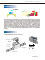
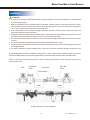
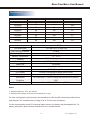
MFG-Series MEMS Mass Flow Meters SIARGO MEMS FLOW SENSOR PRODUCTS User Manual (VC.2) © 2013 Siargo Ltd. MEMS Mass Flow Meters MFG Series User Manual Document No. Issue date: Revision: 07-2013-1 EN 2013.07 C.2 Siargo Ltd. 2041 Mission College Boulevard Suite 250 Santa Clara, CA 95054 USA Tel: +1(408)969.0368 Email: [email protected] © Copyright 2013 by Siargo Ltd. Siargo Ltd. and its subsidiaries reserve the rights to change the specifications and/or descriptions without prior notice. For further information and updates, please visit: www.Siargo.com Mass Flow Meter User Manual Usage This product is designed for industrial gas mass flow metering and control. The safety rating of the product is Ex ia IIC T4. All standard explosive gas handling procedures must be observed for safety during installation and meter usage. This product is powered with lithium ion battery as a standalone unit. When connecting the RS485 communication port with external power, electrical wire and installation with the intrinsic device safety procedure must be observed. The operational conditions of the product are described by its specifications in this manual. Please make sure each of the specifications is fully understood, and acquire the full knowledge of the field where the product will be installed. Please consult the manufacturer before applying it in other working conditions, otherwise the product may not function properly or would be damaged or cause other irreversible consequences. Before operation, leakage test must be performed after installation for safety assurance. All local regulatory requirements must be observed and verified for additional safety precautions. The product performance requires pre-calibration that would best be applied to the specified conditions. Use of the product in other conditions may lead to unexpected results or even to unrecoverable damages. Operation, installation, storage, and maintenance of the product must strictly follow the instructions of this user manual. It is highly recommended that the maintenance should be performed by skilled personnel or trained operators. Unpredicted consequences may otherwise be caused. All the installation, storage, and maintenance of the product must be handled by qualified operators. This user manual should be placed near the product for easy access. Before using the product, the user should read this user manual carefully and completely. It is recommended that the product should be re-calibrated and maintained in every two years or at a time period if deemed necessary. 1 www.Siargo.com Mass Flow Meter User Manual Cautions 1. Do not apply this products to any gas medium that contains excessive liquid or solid debris, that may lead to malfunction or unrecoverable damage of the product. 2. Do not change any software and hardware of the product. All software and hardware of the product have been certified at the time of manufacture. 3. Do not use any unit of the product if suspect of malfunction. 4. Do not use this product in any excessive radiation or vibration environment. 5. Only qualified or accredited personnel by Siargo can perform repair services. Siargo shall not be liable to any products that have be altered or damaged before shipping for product verification and services. 6. When communicating with the meter via the communication port, such as download the historical data from the meter, it is highly recommended to use the software provided by manufacturer or the communication coding should be done by referring the requirements of the user interface described in this manual. 7. The product body is made of aluminum alloy, do not hammer or use sharp tooling during installation. 8. The meter connection are threaded with M-thread and opted with BSPT connectors, please make sure the pipe connectors have the same thread. Force connection would cause unpredicted damage and/or irrecoverable malfunction. 9. The battery pack should not be combined with arbitrary lithium ion battery on market. Consult manufacturer for battery requirements or obtain the replacement from manufacturer. 10. Read the manual carefully before processing of any maintenance or troubleshooting. 2 www.Siargo.com Mass Flow Meter User Manual Table of Content Usage Cautions Introduction Working principle Description Dimensions Product selection Package description Installation Specifications Meter function LCD display Connection Data communications RS485 Pulse output 4~20mA output Automatic data record Safety Maintenance Troubleshooting Storage Warranty Service and order 1 2 4 5 5 6 7 7 8 9 11 11 11 12 12 12 13 13 14 14 15 15 16 17 3 www.Siargo.com Mass Flow Meter User Manual Introduction The MFG series gas flow meters are specially designed for gas mass flow applications. Based on Siargo's proprietary MEMS flow sensing technology and control circuit technology, the all electronic meters are powered by battery and offer a wide dynamic range while maintaining the high sensitivity at the low flow for gas monitor and measurement. The MEMS flow sensors provide direct mass flow capability without additional temperature and pressure compensation. The sensors are packaged using the boundary layer technology that ensures a time-averaged velocity profile across the sensor. The sensing elements are at the center of the flow channel that is designed as a Venturi configuration. The boundary layer condition would force the flow to redistribute at the sensor assembly forming a laminar flow that make it possible for applications in gases with a proper calibration and circuitry compensation. The meters have industrial standard RS485 Modbus communication interface that is ready for remote data logging or networking. The enhanced data safety is realized via the storage designed in the control circuitry that allows the user to program the records of the flow status that can be transmitted via the network or downloaded with a handheld or personal computer with the manufacturer provided software. The meters are best for clean and dry gas flow measurement in gas mass flow applications. Other gases such as water gas with excessive moisture may cause instability due to water condensation. The meters also come with options for GPRS data transmission, pre-paid IC card reader attachment with a shut-off valve. Other convenient features include compact in size for logistic and well isolated standalone unit for reduction of external manipulations. · Wide dynamic range with integrated silicon MEMS flow sensors · Direct measurement of mass flow without additional temperature and pressure compensation · Battery powered standalone unit with long battery life · High accuracy and repeatability at full dynamic range · Standard RS485 Modbus interface for remote data logging or networking · Additional flow status records in circuitry for data safety · Optional GPRS data transmission accessories or pre-paid IC card function · Compact size for easy installation and transportation 4 www.Siargo.com Mass Flow Meter User Manual Working principle Flow direction Time-averaged velocity profile boundary layer Turbulent Free stream Laminar Sensor The MEMS flow sensor senses flow by the calorimetric thermal mass flow measurement principle. A microheater is placed at the middle of two temperature sensors symmetrically placed at upstream and downstream. The cavity below the micro-heater and sensors plays the role of thermal isolation as it is filled with the gas. When the flow passes through the micro-heater, heat will be carried away by the flow medium, and the temperature differences measured by the up- and down-stream temperature sensors are directly proportional to the mass flow of the flow medium. By calibration at the standard conditions, the flow data at the sensor can be properly registered. Compared to the traditional thermal mass flow sensing configuration, the MEMS sensor can be packaged into a plate as indicated by the above graph. The sensor assembly is then placed into the flow channel and the plate assembly serves as the additional flow condition from the boundary layer configuration resulting in a laminar flow. Accurate flow rate is obtained by calibration with the standard gas at the predetermined conditions. Description The meter components are show in the following graph: User interface C Display: Instant flow Accumulated flow Battery status Ambient temperature 5 www.Siargo.com Mass Flow Meter User Manual Dimensions Flow Meters D H G K B L With BSPT connectors F H1 A C L1 F A C L1 H1 440 132 440 137 600 162 660 172 L2 H2 ФD1 n-ФL ФK 386 160 Ф115 4-Ф14 Ф80 396 187 Ф165 4-Ф18 Ф125 543 217 Ф200 8-Ф18 Ф160 577 222 Ф200 8-Ф18 Ф160 With flanges K H2 ФD 1 n -ФL L2 Notes: 1 . Each flow meter has two connectors and the total length is L + C * 2. 2 . For MF65GD and MF80GD, the connector with rectifier should be installed at the entrance. 6 www.Siargo.com Mass Flow Meter User Manual Product selection MF G - - - Gas (A - air; C - CO2; N - N2; O - O2; R - Ar; for other gases, please contact Siargo.) Output** (N- No output; A - 4~20 mA; B-RS485; D-pulse / 0 ~ 5 V; Options: N, A, B, D, AB, AD, BD, ABD for external power model; N for Li-Ion battery model.) Connection (M - M thread; R - With BSPT connectors; F - With Flanges) Maximum flow rate* (Nm3/hr. see detailed in specifications) Power supply (D - 3.6Vdc Li-Ion battery, e - 8~24Vdc external power supply) DN (Pipe inner diameter, mm. Options: 32, 50, 65, 80) Package description Upon unpacking the product, the followings should be intact from the shipping container: 1) This product 2) Cable 3) User Manual 4) QC document or product certificate the product physical integrity should be inspected to ensure no visual damage can be observed. If any items as listed above are missing or any physical damages are observed. Please contact the manufacturer and/or the shipping agents to place a return/exchange or to identify the cause during the transit. If you are uncertain of the installation or have any questions about the shipment, please also contact the manufacturer or the shipping agents before further process. 7 www.Siargo.com Mass Flow Meter User Manual Installation Cautions 1. The meter can be either installed horizontally or perpendicularly. A horizontal installation is recommended for easier meter reading. 2. After the installation pipe on the flow channel is prepared, make sure there is no any metal particles or other harmful debris present inside the flow channel. Avoid strong vibration sources, fire sources, direct expose to rain, or sun, or other sources that may lead to safety issues. 3. Ensure the product is free of visible damages. And check the status of meter power, make sure there is no abnormal in display or other indications. 4. Engage the meter with the prepared installation pipe, make sure the thread or flange can properly seal. Check the meter position and make sure there is no twists or other mechanical faults. 5. The flow measurement direction marked on the meter should be aligned with the flow direction in the flow channel. 6. It is recommended that a high efficient filter should be installed before the meter. 7. To ensure the proper operation of the meter, make sure that there is no presence of foreign gases other than the designated ones. 8. The meter should be installed avoiding valves, sharp turns and other obstacles possibly presented in the The following graphs show the installation configuration. If there is requirement of different pipe size at either upstream or downstream, the size of the pipe diameters should be larger than that of the selected meters. A filter is necessary to avoid heavy particles or debris entering into the meter which may have impact to the meter performance. Filter Pipe before meter Flow meter Pipe after meter Flow direction 3DN 5DN Graphic illustration for the installation. 8 www.Siargo.com Mass Flow Meter User Manual Specifications Model DN (mm) MF32GD 32 10, 16 or 25 0.25 MF50GD 50 40 or 65 0.65 MF65GD 65 100 1.0 MF80GD 80 160 1.6 MF32Ge 32 80 1.6 MF50Ge 50 200 4.0 MF65Ge 65 320 6.4 MF80Ge 80 500 10.0 3 3 Max. Flow rate (Nm /h) Min. Flow rate (Nm /h) ±(1.5+0.5FS)% Accuracy Turn-down Ratio 100:1(MF-GD) / 50:1(MF-Ge) 0.5 MPa Max. Working Pressure Environment Temperature -20 ~ +60℃ Medium Temperature -10 ~ +55℃ Humidity Power Supply < 95%RH (No icing or condensation) 3.6V battery (L3638A)(MF-GD) / 8~24Vdc (Model MF-Ge) Battery life Real time clock life 36 months Output RS485, Pulse; 4~20mA Flowrate; Accumulated flowrate; Battery status LCD display Calibration 10 years Air @ 20℃,101.325kPa Mechanical M-Thread (BSPT-Thread or flange with Mechanical connector) Protection IP66 Ex Proof Ex ia IIC T4 (MF-GD) / None (MF-Ge) Notes: 1. Standard conditions: 20°C; 101,325 kPa 2. Humidity: flow medium must not have condensation or icing. For other configurations, please contact the manufacturer. We can offer customized products from pipe diameter 3/4” and above but not larger than 4” for this series of products. For the communication mode, if no external power sources, the battery may be degraded fast. For battery information, please contact manufacturer or its representatives. 9 www.Siargo.com Mass Flow Meter User Manual Data storage 1. The meter can record and store up to 1000 items daily 2. The time interval of the data storage can be programmed (minimal 3 min and max 240 min.) The storage information include time (hh:mm month day year); flow rate and accumulated flow rate. The maximum items that can be stored are 2000 entries. 3. The other stored items (max 1000) include over flow limit alarm, power failure and sensor errors) Error function Pressure loss 10.0 Error (%) 8.0 350 Pressure Loss (Pa) 300 6.0 4.0 MF32G MF50G MF65G MF80G 250 2.0 200 0.0 -2.0 0 10 20 30 40 50 60 70 80 90 100 150 -4.0 100 -6.0 50 -8.0 -10.0 0 %Qmax 0 10 20 30 40 50 60 70 80 90 100 %Qmax o (at 20 C; 101.325kPa) o (at 20 C, 101.325kPa, low flow models) 10 www.Siargo.com Mass Flow Meter User Manual Meter Functions 1. LCD display C For the meters that is battery powered, it is suggested that the LCD display should be the major interface to access the meter reading if no external power supply will be provided for data communication. The LCD display shows accumulated flow (centered, large characters, in Nm3, and can be displayed from 0.000 to 99999999.999 Nm3 ), instant flow is shown in Nm3/h, and can be displayed from 0.000 to max flow in the corresponding models. The displayed temperature is a ambient temperature. C The standard conditions at calibration are 20°C and 101.325kPa. In case that the meter is malfunctioning due to sensor damage, the “E1” error sign will be shown and flash. C In case that the meter is out of battery (battery power model), the battery sign will indicate an empty battery and an error sign “E5” will be shown and flash. Other alarm code E2~E4 : E2 E3 E4 Sensor covered with excessive foreign materials Hardware error Over flow range 2. Electrical connection Color Definition Description Red Power+ Black GND Green RS485-A RS485 A (+) Brown RS485-B RS485 B (-) Orange Pulse output White Pulse GND Blue Loop+ 4-20mA output Purple Loop- 4-20mA GND 12-24Vdc supply Power ground Pulse output for total Pulse GND 11 www.Siargo.com Mass Flow Meter User Manual 3. Data communications 3-1. RS485 The meter has an RS485 communication port. It is recommended that when this communication port is enabled, an external power supply should be used to ensure the battery life. or purposes of computer control and networking, the RS485 is used for communication with the following preferred settings: Baud rate (Bits per second): 9600 Date bits: 8 Stop bits: 1 Parity: None Flow control: None At the communication : 1. Send 0x9d to the sensor and return with 0x9d 2. Send 0x54 to the sensor and return with 0x54 The interval time between two bytes sent to the sensor must be longer than 5ms. The meter will be communicating at which the data from the sensor will be sent via RS485 in an interval of one second. The data are in the following format: where V=vvvv F=ffffff A=aaaaaaaa V=vvvv\nF=ffffff\nA=aaaaaaaa\nT=t\n;\n Voltage code; mass flow rate (Equal to fff.fff Nm3/h) Accumulated flow (Equal to aaaaa.aaa Nm3) Returning back to normal operation: 1. Send 0x9d to the sensor and return with 0x9d; 2. Send 0x00 to the sensor and return with 0x00; The interval time between two bytes sent to the sensor must be longer than 5ms. Then the meter will be at normal operation at which the data will not be sent via RS232 but display via LCD. 3-2. Pulse output The meter supply pulse output in form of even square wave. The even square wave is composed of 5 V signal high and 0V signal low, and every pulse equal to 1Nm3, 0.1Nm3, 0.01Nm3, 0.001Nm3 or 0.0001Nm3. (default is 1Nm3) 12 www.Siargo.com Mass Flow Meter User Manual 3-3. 4~20mA Connection (External Power Model) 4~20mA Output( LOOP +, Blue ) Input: 24VDC Output: 4~20 mA 3 (4mA = 0 Nm /h; 20 mA = Max. Flow) The connection of the loop load resistor is illustrated at the graph: 4~20mA GND ( LOOP -, Purple) R L(max)=450Ω 3-4. Automatic data record The meter can automatically record mass flow rate, accumulated flow rate and time. To retrieve these data, please contact manufacturer for the necessary user interface software. The data storage interval can be customized and please contact manufacturer for further information. 13 www.Siargo.com Mass Flow Meter User Manual Safety Wetted materials and compatibility The meter body is made of stainless steel and cast aluminum alloy. Sensors comprise of silicon, silicon nitride and silicon dioxide and the sensor surfaces are passivated with silicon nitride and silicon dioxide. The electronic sealing is provided by RTV (room temperature vulcanizing) silicone sealant WR-7 of HOCH3 (SiO) nCH3H. Safety precautions The product is designed for use with clean and dry gas mass flow applications. Although it may be able to apply for other gases, the product cannot be used for gas metrology of fluoride or fluoride containing gases. For updates of the product certification information, please contact manufacturer or visit www.Siargo.com. Use for other gases such as extreme corrosive and toxic may cause the product malfunctioning or even severe damages. The product sealing is ensured to work under working pressure as indicated on the product tag. Although it has been undergone leakage proof before the shipment, cautions and further leakage test are extremely important at installation since any leakage could cause severe safety issue. Attention: any alternation and/or improper use of the product without the permission of the manufacturer can cause unpredicted damages and even injuries or other severe situations. Siargo or any of its employees, subsidiaries shall not be hold and indemnified against such consequences due to such circumstances via improper use of the product. Maintenance Calibration The meter at the time of shipping is fully calibrated at the conditions indicated on the product tag. Use of the product under other conditions will lead to unpredictable results. Please contact the manufacture before such applications. To ensure the meter performance, the meter should be calibrated not over 24 months under normal operation conditions. Maintenance Attention: without prior permission of the manufacturer, please do not attempt to alter any parts of the product as it may cause unrecoverable damages. If there are questions or doubts, please contact manufacturer immediately before further actions. Please ensure the DC power is off before disassembling the meter. All maintenance of the meters should be done by trained and certified personnel by Siargo Ltd. 14 www.Siargo.com Mass Flow Meter User Manual Troubleshooting Errors Possible causes Actions No display 1. Wrong wire connection 2. LCD malfunction 1. Follow user manual, reconnect the wires 2. Check the LCD connection, otherwise replace Display nonzero while no gas flow in the pipe 1. Valve may not be closed completely 2. Pipe leakage 1. Check valve and perform leak tests 2. Check meter offset No flow reading 1. Power supply error 2. Sensor damaged 1. Check power source 2. Check sensor error code, replace sensor Flow rate drops 1. Flow channel clogging 2. Foreign materials deposit on sensor 1. Check and/or change pipe filter 2. Clean or change sensor Communication malfunction 1. Wrong wire connection 2. Wrong baud rate 3. Pin contact error 1. Check wire connections 2. Check baud rate settings 3. Check hardware connections/contacts Battery empty 1. Over lifetime, check current 1. Change battery, check internal battery circuitry No pulse output 1. Wrong wire connection 1. Reconnect the wires For other errors or additional information, please contact the manufacturer. Storage Storage The products if not being installed upon receiving, should be stored in an area without the presence of strong chemicals, electromagnetic interference and vibration. The environments should be dry (<95%RH) and the temperature should be in the range of -25 to 80°C. Transportation During transportation, the products should be properly packaged if not being placed in their original package containers. Such package should be able to resist vibration. Expose to rain or chemicals are strictly prohibited. Labels such as “handle with care”, “avoid collision” should be applied or otherwise clearly marked. 15 www.Siargo.com Mass Flow Meter User Manual Warranty (Effective September 2005) Siargo warrants the products sold hereunder, properly used and properly installed under normal circumstances and service as described in the user's manual, shall be free from faulty materials or workmanship for 180 days for OEM products, and 365 days for non-OEM products from the date of shipment. This warranty period is inclusive of any statutory warranty. Any repair or replacement serviced product shall bear the same terms in this warranty. Siargo makes no other warranty, expressed or implied and assumes no liability for any special or incidental damage or charges, including but not limited to any damages or charges due to installation, dismantling, reinstallation or any other consequential or indirect damages of any kind. To the extent permitted by Law, the exclusive remedy of the user or purchaser, and the limit of Siargo’s liability for any and all losses, injuries or damages concerning the products including claims based on contract, negligence, tort, strictly liability or otherwise shall be the return of products to Siargo, and upon verification by Siargo to prove to be defective, at its sole option, to refund, repair or replacement of the products. No Action, regardless of form, may be brought against Siargo more than 365 days after a cause of action has accrued. The products returned under warranty to Siargo shall be at user or purchaser's risk of loss, and will be returned, if at all, at Siargo’s risk of loss. Purchasers or users are deemed to have accepted this limitation of warranty and liability, which contains the complete and exclusive limited warranty of Siargo, and it shall not be amended, modified or its terms waived except by Siargo’s sole action. This warranty is subject to the following exclusions: 1. Products that have been altered, modified or have been subject to unusual physical or electrical circumstances indicated but not limited to those stated in the user’s manual or any other actions which cannot be deemed as proper use of the products 2. Siargo does not provide any warranty on finished goods manufactured by others. Only the original manufacturer's warranty applies. 16 www.Siargo.com Mass Flow Meter User Manual Services and order Siargo Ltd. is making every effort to ensure the quality of the products. In case of questions, and or product supports, please contact customer service at the address listed below. We will respond your request in a timely fashion and will work with you toward your complete satisfaction. Customer service and all orders should be addressed to Siargo Ltd. 2041 Mission College Boulevard, Suite 250 Santa Clara, California 95054. Tel: 01-(408)969-0368 Email: [email protected]. For orders, please provide accurate and full post address. Siargo will not ship to P.O. Boxes or via a third party. For further information and updates, please visit www.Siargo.com. 17 www.Siargo.com


![[レバーカップリングの特長]](http://vs1.manualzilla.com/store/data/006565020_2-305261d165a4c98659cb76b4a66bb2f9-150x150.png)