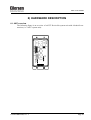
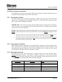
1
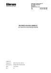
Kokkedal Industripark 4
DK-2980 Kokkedal
Denmark
[email protected]
Tel
+45 49 180 100
Fax
+45 49 180 200
4X37 DEVICE NET SYSTEM
Status and weight transfer using DeviceNet
Applies for:
Program no.:
CONCTR_4.080822.1
Document no.:
0822mu4X37-1
Date:
2009-12-01
Rev.:
1
4X37: User manual
1) CONTENTS
1) CONTENTS.....................................................................................................................................2
2) INTRODUCTION ...........................................................................................................................3
2.1 Introduction.................................................................................................................................3
2.2 DeviceNet specification ..............................................................................................................3
3) DATA EXCHANGE .......................................................................................................................4
3.1 DeviceNet communication using PPO........................................................................................4
3.2 Data formats................................................................................................................................5
3.2.1 Unsigned integer format (16 bit)......................................................................................5
3.2.2 Signed integer format (32 bit) ..........................................................................................5
3.2.3 IEEE754 floating point format (32 bit) ............................................................................6
4) DATA PROCESSING .....................................................................................................................7
4.1 Zeroing, calibration and weight calculation................................................................................7
4.1.1 Zeroing of weighing system.............................................................................................7
4.1.2 Corner calibration of weighing system ............................................................................7
4.1.3 Calculation of uncalibrated system weight ......................................................................8
4.1.4 System calibration of weighing system............................................................................8
5) INSTALATION OF SYSTEM ........................................................................................................9
5.1 Checklist during installation .......................................................................................................9
6) HARDWARE DESCRIPTION .....................................................................................................10
6.1 4X37 overview..........................................................................................................................10
6.2 4X37 front panel description ....................................................................................................11
6.2.1 Connection of power ......................................................................................................11
6.2.2 Connection of loadcells..................................................................................................11
6.2.3 DeviceNet connector ......................................................................................................11
6.2.4 SW1 settings...................................................................................................................12
6.2.5 SWD settings..................................................................................................................12
6.2.6 Light Emitting Diodes (LEDs).......................................................................................13
6.3 Hardware Selftest......................................................................................................................14
6.4 Update times .............................................................................................................................14
7) APPENDIX – INTERNAL FEATURES.......................................................................................15
7.1 4037 DeviceNet module ...........................................................................................................15
7.1.1 SW3 settings...................................................................................................................15
7.1.2 Jumper settings...............................................................................................................15
7.2 4040 communication module....................................................................................................16
7.2.1 SW2 settings...................................................................................................................16
7.2.2 Jumper settings...............................................................................................................16
7.2.3 Light Emitting Diodes (LEDs).......................................................................................17
8) APPENDIX - STATUS CODES ...................................................................................................18
Version: 2009-12-01, rev.: 1
Page: 2
4X37: User manual
2) INTRODUCTION
2.1 Introduction
This document describes the use of a 4X37 DeviceNet system unit from Eilersen Electric.
The 4X37 system unit consists internally of a 4037 DeviceNet module (with the program
listed on the front page) and a 4040 communication module.
The 4X37 system unit is connected to X loadcells (1-4). With the program specified on the
front page, the 4X37 DeviceNet unit is capable of transmitting weight and status for up to
4 loadcells in a single telegram.
It is possible to connect the 4X37 DeviceNet unit to a DeviceNet network, where it will act
as a slave. It will then be possible from the DeviceNet master to read status and weight for
each of the connected loadcells. Functions as zeroing, calibration and calculation of system
weight(s) must be implemented on the DeviceNet master.
Exchange of data between master and slave takes place as described in the following.
2.2 DeviceNet specification
The DeviceNet unit confirms to the following DeviceNet specifications:
Protocol:
Communications form:
Module type:
Baud rates [kbit/sec]:
DeviceNet address:
DeviceNet connection:
DeviceNet
CAN
Slave
125, 250, 500
0-63
Standard 5-pin DeviceNet connector
IMPORTANT: Load cell modules and instrumentation must be placed outside the
hazardous zone if the load cells are used in hazardous ATEX (Ex) area. Furthermore,
only ATEX certified load cells and instrumentation can be used in ATEX applications.
Version: 2009-12-01, rev.: 1
Page: 3
4X37: User manual
3) DATA EXCHANGE
3.1 DeviceNet communication using PPO
DeviceNet communication with the 4X37 DeviceNet unit uses a so called ’parameterprocess data object’ (PPO) consisting of 26 bytes. This telegram (object) is only used when
transferring data from the slave to the master, since no data are transmitted from the master
to the slave. The structure for this telegram is as follows:
Lc
Register
Lc
Lc
Status(0) Signal(0)
0
2
1
3
4
5
6
Lc
Lc
Status(3) Signal(3)
7
20
21
22 23 24 25
The byte order (MSB/LSB first?) for the individual parts of the telegram is determined by
a jumper. Normally this jumper is set from the factory so that LSB comes first. In the following bit 0 will represent the least significant bit in a register.
LcRegister is a word (two bytes) that constitute a bit register for indication of connected
loadcells detected during power on. Hence bit 0-3 will be ON, if the corresponding loadcell
address (LC1-LC4) was detected during power on. LcRegister is always transferred in 16
bit unsigned integer format.
LcStatus(X) is a word (two bytes) that constitute a register containing the actual status for
loadcell X. LcStatus(X) is always transferred in 16 bit unsigned integer format. During
normal operation this register will be 0, but if an error occurs some bits in the register will
be set resulting in an error code. A description of the different error codes can be found in
the chapter STATUS CODES.
LcSignal(X) is a double word (four bytes) constituting a register containing the actual
weight signal from loadcell X. Depending on a jumper LcSignal(X) will be in either 32 bit
signed integer format or in IEEE754 floating point format. This jumper is default set so
transfer of LcSignal(X) is done in 32 bit signed integer format. Note that the value is only
valid if the corresponding LcStatus(X) register is 0 indicating no error present. The resolution of the loadcell signal is 1 gram, so that 12345 gram is represented by the number
12345.
Since only status and weight for the loadcells are transmitted in the telegram, functions
such as status handling, calculation of system weight(s), zeroing and calibration must be
implemented on the DeviceNet master. Please refer to the chapter DATA PROCESSING
for an explanation on how this typically can be done.
Version: 2009-12-01, rev.: 1
Page: 4
4X37: User manual
3.2 Data formats
The DeviceNet communication can transfer data in the following three data formats. If
necessary please refer to other literature for further information on these formats.
3.2.1 Unsigned integer format (16 bit)
The following are examples of decimal numbers represented on 16 bit unsigned integer
format:
Decimal
0
1
2
200
2000
20000
Hexadecimal
0x0000
0x0001
0x0002
0x00C8
0x07D0
0x4E20
Binary (MSB first)
00000000
00000000
00000000
00000000
00000111
01001110
00000000
00000001
00000010
11001000
11010000
00100000
3.2.2 Signed integer format (32 bit)
The following are examples of decimal numbers represented on 32 bit signed integer format:
Decimal
Hexadecimal
-20000000
-2000000
-200000
-20000
-2000
-200
-2
-1
0
1
2
200
2000
20000
200000
2000000
20000000
0xFECED300
0xFFE17B80
0xFFFCF2C0
0xFFFFB1E0
0xFFFFF830
0xFFFFFF38
0xFFFFFFFE
0xFFFFFFFF
0x00000000
0x00000001
0x00000002
0x000000C8
0x000007D0
0x00004E20
0x00030D40
0x001E8480
0x01312D00
Version: 2009-12-01, rev.: 1
Binary (MSB first)
11111110
11111111
11111111
11111111
11111111
11111111
11111111
11111111
00000000
00000000
00000000
00000000
00000000
00000000
00000000
00000000
00000001
11001110
11100001
11111100
11111111
11111111
11111111
11111111
11111111
00000000
00000000
00000000
00000000
00000000
00000000
00000011
00011110
00110001
11010011
01111011
11110010
10110001
11111000
11111111
11111111
11111111
00000000
00000000
00000000
00000000
00000111
01001110
00001101
10000100
00101101
00000000
10000000
11000000
11100000
00110000
00111000
11111110
11111111
00000000
00000001
00000010
11001000
11010000
00100000
01000000
10000000
00000000
Page: 5
4X37: User manual
3.2.3 IEEE754 floating point format (32 bit)
Representation of data on IEEE754 floating point format is done as follows:
Byte1
Byte2
Byte3
Byte4
bit7 bit6
bit0 bit7 bit6
bit0 bit7
bit0 bit7
bit0
7
1
0
-1
-7
-8
-15
-16
S
2 …..…. 2
2
2 ……... 2 2 ………….... 2
2 ………..…. 2-23
Sign
Exponent
Mantissa
Mantissa
Mantissa
Formula:
Value = (-1)S * 2(exponent-127) * (I+Mantissa)
Example:
Byte1
0100 0000
Byte2
1111 0000
Byte3
0000 0000
Byte4
0000 0000
Value = (-1)0 * 2(129-127) * (1 + 2-1 + 2-2 + 2-3) = 7.5
Please note that if transfer of MSB first has been selected, the byte with the “sign” will
come first in the weight indications, and if LSB first has been selected (default setting) the
byte with the “sign” will come last in the weight indications.
Version: 2009-12-01, rev.: 1
Page: 6
4X37: User manual
4) DATA PROCESSING
4.1 Zeroing, calibration and weight calculation
Calculation of system weight(s) is done by addition of the weight registers for the loadcells
belonging to the system. This is explained below. Note that the result is only valid if all
status registers for the loadcells in question indicate no errors. It should also be noted that
it is up to the master to ensure the usage of consistent loadcell data when calculating the
system weight (the used data should come from the same telegram).
4.1.1 Zeroing of weighing system
Zeroing of a weighing system (all loadcells in the specific system) should be performed as
follows, taking into account that no loadcell errors may be present during the zeroing procedure:
1)
2)
The weighing arrangement should be empty and clean.
The DeviceNet master verifies that no loadcell errors are present, after which it
reads and stores the actual weight signals for the loadcells of the actual system in
corresponding zeroing registers:
LcZero[x]=LcSignal[x]
3)
After this the uncalibrated gross weight for loadcell X can be calculated as:
LcGross[X] = LcSignal[X] – LcZero[X]
4.1.2 Corner calibration of weighing system
In systems where the load is not always placed symmetrically the same place (for example
a platform weight where the load can be placed randomly on the platform when a weighing
is to take place), a fine calibration of a systems corners can be made, so that the weight indicates the same independent of the position of the load. This is done as follows:
1)
2)
3)
Check that the weighing arrangement is empty. Zero the weighing system.
Place a known load (CalLoad) directly above the loadcell that is to be corner calibrated.
Calculate the corner calibration factor that should be multiplied on the uncalibrated gross weight of the loadcell in order to achieve correct showing as:
CornerCalFactor[x] = (CalLoad)/(LcGross[x])
After this the determined corner calibration factor is used to calculate the calibrated gross weight of the loadcell as follows:
LcGrossCal[x] = CornerCalFactor[x] * LcGross[x]
Version: 2009-12-01, rev.: 1
Page: 7
4X37: User manual
4.1.3 Calculation of uncalibrated system weight
Based on the loadcell gross values (LcGross[x] or LcGrossCal[x]), whether they are
corner calibrated or not, a uncalibrated system weight can be calculated as either:
Gross = LcGross[X1] + LcGross[X2] + …
or:
Gross = LcGrossCal[X1] + LcGrossCal[X2] + …
4.1.4 System calibration of weighing system
Based on the uncalibrated system weight a system calibration can be made as follows:
1)
2)
3)
Check that the weighing arrangement is empty. Zero the weighing system.
Place a known load (CalLoad) on the weighing arrangement.
Calculate the calibration factor that should be multiplied on the uncalibrated system weight in order to achieve correct showing as:
CalFactor = (CalLoad)/(Actual Gross)
After this the determined calibration factor is used to calculate the calibrated system weight as follows:
GrossCal = CalFactor * Gross
If the determined calibration factor falls outside the interval 0.9 to 1.1 it is very
likely that there is something wrong with the mechanical part of the system. This
does not however apply to systems that do not have a loadcell under each supporting point. For example on a three legged tank with only one loadcell, you should
get a calibration factor of approximately 3 because of the two “dummy” legs.
Version: 2009-12-01, rev.: 1
Page: 8
4X37: User manual
5) INSTALATION OF SYSTEM
5.1 Checklist during installation
During installation of the system the following should be checked:
1)
If necessary the DeviceNet master should be configured to communicate with the 4X37 DeviceNet
system unit using the supplied EDS file.
2)
The loadcells are mounted mechanically and connected to BNC connectors in the front panel of the
4X37 system unit.
3)
The 4X37 DeviceNet system unit is connected to the DeviceNet network using the DeviceNet connector in the front panel of the 4X37 system unit. If necessary a possible termination of the DeviceNet network is made at this DeviceNet slave.
4)
Use SW1 in the front panel of the 4X37 system unit to select any features associated with SW1 on
the 4040 communication module.
5)
Use SWD.1-SWD.6 in the front panel of the 4X37 system unit to select the communication address
of the 4X37 DeviceNet system unit.
6)
Use SWD.7-SWD.8 in the front panel of the 4X37 system unit to select the communication speed
(baudrate) of the 4X37 DeviceNet system unit.
7)
Power (24VDC) is applied at the 2 pole power connectors in the front panel of the 4X37 system
unit as described in the hardware section, and the DeviceNet communication is started.
8)
Verify that the MS lamp and the NS lamp both end up green.
9)
Verify that the TxDN lamp is lit/flashes vague green.
10)
Verify that the TxLC lamp (yellow) is lit (turns on after approx. 5 seconds).
11)
Verify that the two TxBB lamps (green) are lit (both lit after 10 seconds).
12)
Verify that NONE of the 1, 2, 3 or 4 lamps (red) are lit.
13)
Verify that the 4X37 DeviceNet system unit has found the correct loadcells (LcRegister), and that
no loadcell errors are indicated (LcStatus(x)).
14)
Verify that every loadcell gives a signal (LcSignal(x)) by placing a load directly above each loadcell one after the other (possibly with a known load).
The system is now installed and a zero and fine calibration is made as described earlier.
Finally verify that the weighing system(s) returns a value corresponding to a known actual
load.
Note that in the above checklist no consideration has been made on which functions are
implemented on the DeviceNet master.
Version: 2009-12-01, rev.: 1
Page: 9
4X37: User manual
6) HARDWARE DESCRIPTION
6.1 4X37 overview
The following figure is an overview of a 4X37 DeviceNet system unit with 4 loadcell connections (i.e. a 4437 system unit):
4437A
J3
ATEX
J2
0
24V
24V
0
1
DeviceNet
1
SW1
5
4
2
ON
1
3
8
SWD
1
MS
NS
TxDN
TxBB
D1
Version: 2009-12-01, rev.: 1
4
ON
TxLC
TxBB
1
2
3
4
Page: 10
4X37: User manual
6.2 4X37 front panel description
This chapter describes the connections, DIP-switch settings and lamp indications that are
available on the front panel of the 4X37 system unit.
6.2.1 Connection of power
The 4X37 system unit is powered by applying +24VDC on the green two pole connectors
(J2 and J3) as specified on the front panel of the 4X37 system unit. This powers the entire
4X37 system unit including the loadcells.
IMPORTANT: The used power supply must be stable and free of transients. It may therefore be necessary to use a separate power supply dedicated to the weighing system, and not
connected to any other equipment.
NOTE: If the loadcells are to be placed inside an EX area, then the 4X37 system unit itself
MUST be placed outside the EX area, and the 4X37 system unit MUST be supplied as follows:
1) The 2 pole connector (J3), located to the right above the 4 pole DIP-switch block, MUST be powered by a 4051A power supply (+24VDC ATEX approved) from Eilersen Electric.
2) The 2 pole connector (J2), located to the left above the 5 pole connector (DEVICENET), MUST be
powered by a separate +24VDC, that has NO connection to the ATEX approved +24VDC from the
above mentioned 4051A power supply.
6.2.2 Connection of loadcells
The loadcells must be connected to the available BNC connectors in the front panel of the
4X37 system unit. The loadcells are connected starting with the connector marked 1 and
continuing onwards in rising order. Thus if three loadcells are to be connected, they should
be connected to the BNC connectors marked 1, 2 and 3.
6.2.3 DeviceNet connector
The front panel of the 4X37 system unit is equipped with a five pole connector with a
standard DeviceNet interface. This allows for direct connection to a DeviceNet network
using standard DeviceNet connectors. The specific terminals in the connector have the following function as described in the DeviceNet Specification:
Connection
Function
Color
DEVICENET.1
DEVICENET.2
DEVICENET.3
DEVICENET.4
DEVICENET.5
VCAN_L
SHIELD
CAN_H
V+
(Black)(0VDC input)
(Blue)
(Grey)
(White)
(Red)(24VDC input)
Version: 2009-12-01, rev.: 1
Page: 11
4X37: User manual
6.2.4 SW1 settings
The front panel of the 4X37 system unit is equipped with a 4 pole DIP switch block named
SW1. These switches are mounted on the 4040 communication module, and they are
ONLY read during power-on. When the 4040 communication module is equipped with
standard program, their functionality is as follows:
Sw1.1
FIR Filter
OFF
ON
No filter
30 taps
SWITCH
Sw1.2-Sw1.4
FUNCTION
Reserved for future use
6.2.5 SWD settings
The front panel of the 4X37 system unit is equipped with a 8 pole DIP switch block named
SWD. These switches allow setting of the DeviceNet communication address and DeviceNet communication speed (baudrate) of the 4X37 DeviceNet system unit. This DIP
switch block has the following function:
SWITCH
FUNCTION
SWD.1-SWD.6 Selection of DeviceNet Node Address (NA)
The address (0-63) is selected as the DIP-switches are binary coded, so SWD.6 is
MSB and SWD.1 is LSB. Note that these switches are only read during power on.
SWD.7-SWD.8 Selection of DeviceNet Data Rate (DR)
The desired baudrate is set according to the table below. Note that these switches are
only read during power on.
SWD.8
SWD.7
OFF
OFF
ON
ON
OFF
ON
OFF
ON
Version: 2009-12-01, rev.: 1
4X37 DeviceNet Data Rate (DR)
125 kbps
250 kbps
500 kbps
Not allowed
Page: 12
4X37: User manual
6.2.6 Light Emitting Diodes (LEDs)
The front panel of the 4X37 system unit is equipped with a number of status lamps (light
emitting diodes). These have the following functionality:
LED
MS
(Green/Red)
NS
(Green/Red)
FUNCTION
Module Status LED
The 4037 Module Status LED, that can be lit/flashing in different colors depending
on the status of the module. The function of the MS LED is given in the table below.
Network Status LED
The 4037 Network Status LED, that can be lit/flashing in different colors depending
on the status of the network. The function of the NS LED is given in the table below.
TxDN
Transmit DeviceNet
(Green)
The 4037 module transmits on DeviceNet (CAN bus).
TxBB (Left)
(Green)
D1
4037 communication with 4040 module (internal)
4037 DeviceNet module is transmitting to 4040 module.
Reserved for future use
(Green)
TxLC
(Yellow)
TxBB (Right)
(Green)
1
(Red)
2
(Red)
3
(Red)
4
(Red)
Version: 2009-12-01, rev.: 1
4040 communication with loadcells
4040 communication module is communicating with loadcells.
4040 communication with 4037 DeviceNet module (internal)
4040 communication module is transmitting to 4037 DeviceNet module.
Status for loadcell 1
Bad connection, loadcell not ready or other error detected.
Status for loadcell 2
Bad connection, loadcell not ready or other error detected.
Status for loadcell 3
Bad connection, loadcell not ready or other error detected.
Status for loadcell 4
Bad connection, loadcell not ready or other error detected.
Page: 13
4X37: User manual
The MS and NS LED’s can in conjunction with the table below be used for error finding.
Light
emitting
diode
Color
MS
Green
Red
NS
Status
ON
Normal Operation. Communication performed normally.
Flashing Standby State. The unit needs supervision.
ON
Unrecoverable fault. A timer error, memory error or
other system error. The unit may need replacing.
Flashing Recoverable fault. Configuration error, DIP-switch not
set correct or similar error. Correct error and restart unit.
---
OFF
Green
ON
Red
---
Description
No power. The power is disconnected or the unit is being
restarted.
On-Line, Connection OK. The unit is On-Line and a
connection with the master has been established.
Flashing On-Line, No Connection. The unit is On-Line but no
connection to the master has been established.
ON
Critical Communication Error. The unit has detected an
error that makes it impossible to communicate on the network (duplicate MAC Id or Bus-Off error).
Flashing Communication Time-Out. One or more I/O connections
are in the Time-Out state.
OFF
No power/Off-line. The device may not be powered.
6.3 Hardware Selftest
During power-on the 4X37 DeviceNet system unit will perform a hardware selftest. The
test will cause the light emitting diodes D1, MS and NS to flash shortly one at a time.
6.4 Update times
The 4X37 DeviceNet system unit samples the loadcell signals over a period of 200 mS. The
hereby found loadcell signals are used in the DeviceNet communication until new signals are
achieved when the next sample period expires. Update times across the DeviceNet communication depends on the specific DeviceNet configuration (selected baudrate, number of slaves,
scan times etc.).
Version: 2009-12-01, rev.: 1
Page: 14
4X37: User manual
7) APPENDIX – INTERNAL FEATURES
7.1 4037 DeviceNet module
This chapter describes possible connections, DIP-switch settings and jumper settings that
are available internally on the 4037 DeviceNet module. These will normally be set from
Eilersen Electric and should only be changed in special situations.
7.1.1 SW3 settings
The 4037 DeviceNet module is internally equipped with a 4 pole DIP switch block named
SW3. This DIP switch block has the following function:
SWITCH
Sw3.1-Sw3.4
FUNCTION
Reserved for future use
7.1.2 Jumper settings
The 4037 DeviceNet module is internally equipped with 5 jumpers. These jumpers have
these functions:
JUMPER
JU1
FUNCTION
Reserved for future use
(normal default factory setting is OFF)
JU2
Test mode
JU2 OFF: Normal mode (default at delivery and should not be changed)
JU2 ON: Test mode
The jumper must be OFF during normal operation.
JU6
Test mode
JU6 OFF: Normal mode (default at delivery and should not be changed)
JU6 ON: Test mode
The jumper must be OFF during normal operation.
JU7
Selection of (32 Bit Signed Integer) / (IEEE754) data format
The jumper determines if the weight indications in the telegram are in 32 bit signed
integer or in IEEE754 floating point format.
OFF: 32 bit signed integer format (normal setting from factory)
ON: IEEE754 floating point format
JU8
Selection of LSB/MSB data format
The jumper determines the byte order in which data are transmitted/received.
OFF: LSB first (normal setting from factory)
ON: MSB first
Version: 2009-12-01, rev.: 1
Page: 15
4X37: User manual
7.2 4040 communication module
For information on jumper settings, DIP-switch settings, LED status lamps etc. on the 4040
communication module that is not covered in the above, please refer to the separate documentation that describes the 4040 communication module and its specific software.
7.2.1 SW2 settings
The 4040 communication module is internally equipped with a 8 pole DIP switch block
named SW2. Please note that these switches are ONLY read during power-on. This DIP
switch block has the following function when the 4040 communication module is equipped
with standard program:
Sw2.1
Sw2.2
Sw2.3
Number of loadcells
OFF
ON
OFF
ON
OFF
ON
OFF
ON
OFF
OFF
ON
ON
OFF
OFF
ON
ON
OFF
OFF
OFF
OFF
ON
ON
ON
ON
1
1
2
3
4
5
6
6
SWITCH
Sw2.4-Sw2.8
FUNCTION
Reserved for future use
7.2.2 Jumper settings
The 4040 communication module is internally equipped with 4 jumpers named P2, P3, P4
and P5. In this system these jumpers must be set as follows:
JUMPER
P2
P3
P4
P5
Version: 2009-12-01, rev.: 1
POSITION
OFF (Loadcell connected to 4040 NOT accessible using SEL1)
OFF (Loadcell connected to 4040 NOT accessible using SEL6)
OFF (Loadcell connected to 4040 NOT accessible using SEL1)
OFF (Loadcell connected to 4040 NOT accessible using SEL6)
Page: 16
4X37: User manual
7.2.3 Light Emitting Diodes (LEDs)
The 4040 communication module is internally equipped with a number of status lamps
(light emitting diodes). The lamps have the following functionality when the 4040 communication module is equipped with standard program:
LED
FUNCTION
D11
Reserved for future use
(Red)
D12
Reserved for future use
(Red)
D13
Reserved for future use
(Red)
D14
Reserved for future use
(Red)
Version: 2009-12-01, rev.: 1
Page: 17
4X37: User manual
8) APPENDIX - STATUS CODES
Status codes for the connected loadcells are shown as a 4 digit hex number. If more than
one error condition is present the error codes are OR’ed together.
CODE
(Hex)
CAUSE
0001
0002
0004
0008
0010
Reserved for future use
Reserved for future use
Reserved for future use
Reserved for future use
0020
New loadcell detected or loadcells swapped
Power the system off and back on. Then verify that all parameters are acceptable.
0040
No answer from loadcell
Bad connection between loadcell and loadcell module?
Bad connection between loadcell module and communication module?
0080
No answer from loadcell
Bad connection between communication module and master module?
Reserved for future use
Reserved for future use
Reserved for future use
0100
0200
0400
0800
1000
2000
4000
8000
Power failure
Supply voltage to loadcells is to low.
No loadcell answer
Bad connection between loadcell and loadcell module?
Bad connection between loadcell module and communication module?
Bad connection between communication module and master module?
Bad setting of DIP switches on loadcell or communication module?
Reserved for future use
Reserved for future use
Reserved for future use
Reserved for future use
Please note that the above listed status codes are valid when the 4040 communication
module is equipped with standard program.
Version: 2009-12-01, rev.: 1
Page: 18