1
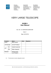
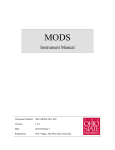
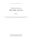
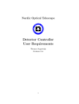
DeVeny Spectrograph
Discovery Channel Telescope
Reference and Operations Guide
v0.1 30 April 2015 T. Bida, S. Levine
1) History/Overview
The DeVeny spectrograph was built and known at Kitt Peak National Observatory (KPNO) as
the KPNO White Spectrograph, and had a long career at the 36" telescope there before being
retired. Lowell Observatory acquired the spectrograph from KPNO on indefinite loan in 1998, a
new CCD camera was built for it, and the instrument was further modified for installation on the
72” Perkins telescope in 2005. Following 8 years of service there, it was removed in 2013 for
upgrades for installation on the DCT instrument cube in February 2015, where it is currently
undergoing commissioning on the DCT. The spectrograph was designed for f/7.5 telescope
optics, and new re-imaging optics were designed and fabricated to match the spectrograph with
DCT's f/6.1 beam.
The DeVeny/DCT Spectrograph system introduces the f/ratio matching optics, a deep depletion
version of the e2v CCD42-10 CCD (2048x515 13.5 micron pixels) mounted in a new dewar with
a Stirling cycle cooler, and a slit-viewing acquisition camera. Behind the shutter, decker, and
slit-jaws there is a pupil-matching lens, order-blocking filters, an off-axis parabola collimator,
and a grating carriage that holds one of a set of 128x154mm plane reflection gratings. The
image is formed on the CCD by the f/1.25 Wynne camera, which has two powered reflective
surfaces and a series of weak fused silica refractive correction surfaces. The secondary ‘mirror’
(an aluminized rectangular spot on a key surface) introduces a substantial central obscuration in
the camera. Four spectral calibration lamps (Hg, Ne, Cd, and Ar) are mounted on the
spectrograph front plate and are remotely controllable.
The spectrograph provides low-resolution optical spectra at R500-4000 over a wavelength range
from 3200 Å to 1 micron, with a slit length up to 2 arcmin on the DCT. The grating complement
currently includes several 1st-order blazed gratings, from 150g/mm up to 2160g/mm (see table
below for details; other stock rulings are commercially available). An upgrade project is planned
to motorize the grating tilt, slit width, and collimator focus stages and configure them to be
operable through remote control software.
The CCD detector is operated by a Gen III ARC controller from a Linux computer. The
software that interfaces directly with the controller is called LOIS, and the user interface
software is called LOUI. Both LOIS and LOUI were developed at Lowell and are under active
maintenance and development.
1
2) Quick reference specifications and operating options
a) Gratings:
All the gratings are 128 x 154 mm 1st-order blazed plane reflection gratings. The Lowell
DeVeny grating complement is shown in Table I. Instrumental efficiencies will be remeasured
during upcoming commissioning time.
Table I. DeVeny Gratings
g/mm
Blaze
Wavelength (Å)
Dispersion
(Å/pix)
Free Spectral
Range (Å)
R
(2.5pixel)
150
5000
4.3
8800
450
300
5000
2.17
4440
920
400
8500
1.66
3400
2850
1200
5000
0.58
1180
3450
2160
5000
0.33
670
5250
Comments
GoldCam 201
4630 Å red tilt limit
b) Shutter and filter wheels:
The iris shutter is made by Uniblitz, and was replaced with a new shutter for the DCT
installation. It is positioned above the slit assembly, therefore, the slit-viewing camera will be
blocked from the sky and the images will be blank when the CCD is reading out. The
photometric accuracy of the new shutter has not yet been measured.
The order blocking filters are installed in the rear filter wheel. These are 1.75in x 2mm thick
circular filters fabricated from Schott glasses, polished to 1 wave/inch with 1 arcmin wedge
maximum, and broad-band AR coated on both sides. Both filter wheels are 5-position, with an
empty position available in each.
Table II. Filter Wheel Positions (ND = neutral density grade)
Wheel
Position C
Position 1
Position 2
Position 3
Front filters
Clear
2.5mag ND
5mag ND
7.5mag ND
Rear filters
Clear
GG420
GG495
OG570
2
c) Slit and Decker:
The maximum slit length without the decker is about 2.5 arcmin. With the decker, the maximum
slit length is 1.9 arcmin. The decker plate and second set of slit jaws are being repolished and
coated (April-June 2015). The slit-jaws that are installed have somewhat poor surface quality
due to a failed coating run. The slit width is adjustable using the micrometer.
Slit adjustment:
Focal plane plate scale:
0.153 mm/arcsec
(or 0.006 inches/arcsec on the adjustment micrometer)
Minimum slit width:
approx. 0.15 arcsec (0.0005 in)
Maximum slit width:
> 40 arcsec
Slit position angle:
adjustable 0-360 deg with the Cass rotator
d) Calibration lamps:
The arc calibration lamps are nominally operated through a widget on the DeVeny LOUI, that
switches a PDU mounted on the instrument.
Arc lamps: Hg, Ne, Ar, Cd
Flat lamps: provided by the existing DCT boom-mounted flat lamp system, or the top-ring
mounted lamps.
e) Slit viewing camera:
The slit viewing camera is a Lodestar X2 made by Starlight Xpress. The detector is a Sony
ICX829AL ExView2 interline CCD, with 752 x 580 pixels. The pixels are 8.6 x 8.3 microns
with embedded vertical antiblooming circuitry. The QE peaks at about 77% at 620nm, and drops
to 45% at 400 and 770nm. The read noise is nominally less than 10e-, and full well is greater
than 50,000 e- (per manufacturers literature). Typical gain is 0.4 e-/ADU. The camera is
uncooled so the hot pixel count increases with exposure time.
The camera is USB-based and is run by a linux machine using the GoQat software package, and
operated for observing by a custom IDL GUI. Typical image download times are roughly 0.2 s
using USB2. The camera is always operated binned 2x2 to avoid the interline response pattern.
Specifications:
Pixel scale: 0.253 arcsec/binned pixel
Image size: 376 x 290 16-bit pixels
Field of view: 95 x 73 arcsec
f) CCD camera:
A major component of the DeVeny/DCT upgrades is the new CCD camera, developed at Lowell,
and operated with ARC Gen-III control electronics. The CCD is an e2v CCD42-10 deep
depletion device, which replaces a standard silicon CCD to reduce fringing in the red end of the
spectrum. The CCD has 2048 x 512 pixels, each 13.5 microns square. The device is AR coated
with e2v’s 4-layer Astro-broadband AR coating.
Specifications:
Gain:
Read noise:
Linearity:
1.52 e-/ADU (in the lab, to be verified on the DCT)
4.9 e- (to be verified on the DCT)
tbd
3
Operating T: -110 C
Dark current: tbd (very low though)
Read out time: 8 s
Pixel scale: 0.34 arcsec/pixel
3) Basic Operations
Items covered here are spectrograph specific. More general observational procedures, like
setting up target lists and sending targets, are well-covered in the LMI user manual.
a) Slit viewing camera operation
i) Starting the control software: GoQat and slitviewg:
The slit viewing camera is operated through USB connections on both the instrument and
computer room ends, connected by a fiber-based extender; the extender unit on the telescope has
a separate DC power supply. The camera is controlled by the computer vishnu, through the
GoQat software package, and operated on-sky through the locally-developed IDL ‘slitview’
package.
To start up the slit viewing camera and software:
GoQat:
i. From a local terminal window on baggins, login to the control computer vishnu:
ssh -X lois@vishnu, password: lois password
ii. In this terminal, type ‘goqat.start’. This script will check for and create a data directory
titled with the current UT date, and start up GoQat . The script is:
/home/lois/bin/goqat.start.
iii. In the GoQat GUI (figure 1):
Camera menu:
Connect to CCD camera.
Camera tab:
Set H and V binning: 2
Set Exposure: 1 (s)
Files tab:
Folder for saving CCD image: Select Other:
i.e. lois/deveny/2015mmdd
Autosave each image: check
Base file name for CCD image: enter i.e. ‘2015mmdd’
Save files with number starting from:
start at 1 and adjust as necessary.
IDL slitview package:
i.
Open a second terminal window to vishnu, logging in as in (i).
ii. Change directory to the working data directory for the night:
i.e. /home/lois/deveny/2015mmdd
iii. Type "idl" to launch idl. The slitview code automatically compiles.
iv. At the idl prompt: type ‘slitviewg’. This launches the slit viewing camera top level
control GUI (figure 2).
4
Figure 1. GoQat camera software interface.
v.
Running the slitviewg GUI:
1) Acquire Image:
take an image, with integration time ‘ttime’. The file name is
written to the following field. To display the compass rose in the proper on-sky
orientation, fill in the PA field with the current slit PA (measured E of N).
2) Read File:
loads the image file name in the field into the display.
3) MARK Star:
fit a 2-D Gaussian function to a selected star in the field of view
(click button, then select star with the cursor and click). A 1-D radial plot with the fitted
curve is displayed in the upper right window, with a contour plot of the selected star and
fit parameters displayed in the middle-right window.
4) Repeat Acquire:
Take ‘Numexp’ images in sequence with the specified interval inbetween. Images are currently saved, so caution is advised when executing long
sequences. This function can be used to monitor tracking. To interrupt the sequence,
regain focus in the IDL session window, and type ^C, followed by ‘@recover’. To avoid
buffer overflow crashes of GoQat on the server, set the interval between exposures to 5 s
or longer.
5) Point REF:
Constructs the pointing offset to put the selected star in a reference
position, approximately 5arcsec above the center of the slit. The current slit PA must be
entered in the top right field. A verification image is automatically taken following the
offset. See note 7 below regarding offsets.
5
6) Point SLIT:
Constructs the pointing offset to put a star approximately at the slit
center position, with specified slit PA. A verification image is automatically taken
following the offset.
7) Offset RA/DEC:
Offsets the pointing position in RA and DEC in arcseconds in the
tangent plane. Parameters are dRA, dDEC, which are in arcseconds, with positive East
and North respectively. The offsets are absolute with respect to the original science target
position. This means that offsets of 0,0 should always put the target back in the original
position. In order to establish a new origin after a non-zero absolute offset, ask the TO to
absorb the current offsets, and set these fields to 0. Any subsequent offset will be a new
absolute offset from the new origin.
See also the discussion in S.6 on open loop vs. guided offsets, and why open loop offsets
are preferred for target set up.
8) M2 Focus Loop:
Execute a focus loop with an imaged star on the slit plane by
piston of the secondary mirror (M2) using the telescope active optics system (AOS).
‘Nexp’ images can be stacked at each of ‘nSteps’ focus positions, separated by ‘Step’
with central position ‘Center’. The focus loop can be monitored through the psf fitting
output and messages printed to the terminal window, and the focus curve data and fit is
plotted in the lower right window. M2 is left at the end of travel, and the predicted
postion for minimum focus is printed in the ‘Send M2 Focus’ field, which must be
clicked to send the move to the AOS.
9) Send M2 Focus:
Send a focus offset value to the Active Optics System. The value
is entered in microns.
6
Figure 2. IDL slitview control GUI.
b) CCD camera operation
The DeVeny camera LOIS/LOUI operations are very similar to that for LMI. At the DCT site
baggins is the UI desktop machine.
i.
The camera operating software ‘lois’ is run from the host deveny; open a terminal
window:
Login: ssh obsdeveny@deveny
Password: On the white board.
ii.
On the deveny terminal, type ‘st’ to check on the status of several processes: lois, the ntp
client, and sequester. If npt is not running, type ‘./timefix’. If sequester is not running,
the host deveny will need to be rebooted: contact plc, szk, or [email protected].
iii.
On baggins, if there is a DeVeny LOUI in the dock, open it, and then exit the application
from the top-level pull-down menu. Then, double click on the DeVeny LOUI in the
upper right corner of the left hand screen to start a new copy. The DeVeny LOUI is
shown in Figure 3. If both lois and temperature logging are running, click ‘Stop Series’
to halt the logging.
iv.
If lois is not running, type ‘lois &’ in the deveny terminal. A series of lois startup
messages will be printed in both the terminal and the lois console on LOUI.
v. In DeVeny LOUI, click on ‘Initialize LOIS’ in the upper right to enable the camera
control, storage path, and telescope telemetry capabilities in LOIS.
vi.
There are several DeVeny-specific LOUI features of note:
7
vii.
1) In the Image perspective, the DeVeny pulldown menu provides several graphical
functions with region of interest mouse selection for quick-look analysis, including
Gaussian profile fitting of spectral lines and spatial continuum width, and a plot
function to view an average full spectral profile.
2) In the DeVeny Control tab, the Comparison Lamps widget provides access to arc
lamp power controls; click Enable for access.
3) In the User Button tab, the deveny_FitsSe button provides fields for entry and storage
in image headers of keywords for the grating in use and its tilt, the slit width, and
collimator setting.
At the end of the observing session:
1) In the Comparison Lamps widget, ‘Enable’ the lamps. Then, click ‘All Lamps Off’.
2) Click the blue ‘Get Temp’ icon in the upper right of application to start temperature
logging.
3) Exit the application with the top-level pull down menu.
See the LMI user manual for more discussion of camera operations and LOUI and IRAF quicklook software, as DeVeny camera operations are very similar.
Figure 3. DeVeny LOUI. The displayed and stored images are oriented with red to the left, and blue to the
right.
8
c) Set-up of the spectrograph mechanical stages
The mechanical adjustments of the slit jaws, decker plate, filter wheels, and grating tilt are
located on the left-front side of the instrument. The collimator focus adjustments are made at the
back end of the instrument, at the outside radius of the cassegrain rotator. When the telescope is
parked at the zenith, a rotator physical angle of 180 deg will provide good access to the
mechanisms. Figure 4 shows the layout of the components in this area.
i) Setting the slit width with the micrometer head
(a) Unlock the micrometer by rotating the knurled knob at its base CCW. Turn the micrometer’s
ratcheting knob GENTLY in the clockwise direction until it approaches zero and then clicks.
This will set the slit width to its minimum position, which is approximately 0.0005 inch.
(b) Open the bi-parting slit jaws by rotating the micrometer CCW and set the desired width. The
scale is 0.006 inch/arcsec (with 0.025”/revolution). Lock the head by turning the knurled
know CW.
ii) Selecting the decker setting
The decker is not currently installed (April 2015).
Figure 4. Adjustment mechanisms for the slit jaws (micrometer head), front and rear filter wheels, and
the grating drive (speed reducer and motor switch below).
9
iii) Selecting front and rear filters
There are two wheel knobs on the L side of the instrument, one that rotates the front (pre-slit)
filter wheel, and the other the rear (post-slit) order-blocking filter wheel. The ‘default’ settings
are C and C (clear and clear). Rotate the knobs to select the filters needed. Under most
circumstances the front wheel should be in the clear position.
iv) Adjusting grating tilt
The grating tilt is adjusted using the AC motor and speed reducer assembly on the L side of the
instrument, by manually toggling the switch located there; the switch direction is labeled
‘Longward’ or ‘Shortward’. The ratio of the speed reducer can be increased for fine control of
the position by pulling out the spring-loaded shaft handle and rotating it between positions.
v) Focusing the spectrograph
The DeVeny is focused by piston of the collimator. This needs to be done up on the observing
level. To adjust and measure focus:
1) Turn on an appropriate arc lamp(s); the lamps take several minutes to warm up. Bring up
a laptop so you can VNC into baggins to take arc spectra and measure the line widths.
2) Loosen the clamp on the side of the white cylindrical cover at the back end of the
spectrograph by turning it CCW a few turns.
3) The mirror piston position is adjusted by turning the knob at the end of the white cover.
There is a three digit mechanical readout showing the position on the right-rear of the
spectrograph. The units are 0.001 inch, and a reasonable step size is 30 units or 0.030 in.
4) Starting from one end of focus, take an arc spectrum and measure the width of a line near
the center of the spectrum at each position. Line widths can be measured directly within
the LOUI imaging pane with: DeVeny pull-down menu > Arc-line FWHM task.
5) Due to astigmatism in the camera, the projected line width will go through a minimum
before approaching the optimum line width, which would be approximately 3.5
pixels/arcsec slit width for the low dispersion gratings, including anamorphic
magnification. Once you have a good focus, tighten the clamp and turn off the arc lamp.
vii) To change out gratings:
The gratings are now located in the cabinet in the instrument lab, on the shelf below the LMI
filters. Use the grey molded grating case on the table to transport a selected grating to the
observing level. Take only 1 grating up at a time, to leave an open slot for the grating to be
removed from the spectrograph.
(a) Move the telescope to this position: El=45 deg, Cass rotation at 90 deg.
(b) Move the grating tilt to 10.
(c) Slide back the retention lever and open the access port.
(d) Locate the grating cover in the case; slide the cover into the slot on the camera side of
the cell.
(e) The grating cell will be removed with motion down and back; hold onto the cell
handle with 2 hands at all times. Put the removed cell in the open slot in the case.
(f) Pick up the grating cell to be installed, and slide it into the carriage by lining up the
steel guides in the carriage slots. Push the cell fully into the carriage to properly seat
the holding spring plungers in the detents. Give the cell another push left to define it
flush against the guide.
10
(g) While restraining the grating cell with a hand on the handle, slide out the grating
cover and place it in the case. Close and lock the case.
(h) Close the access hatch and lock it with the lever.
(i) Rotate the grating to the desired angle (the read scale units are not degrees). Some
example grating settings are shown in Table III, including suggested collimator focus
settings. A sample arc line spectrum is shown in Figure 5.
Table III. Example grating settings (approximate)
Grating
(g/mm)
Grating tilt
Wavelength Range (Å)
Collimator Focus
(for nominal line width)
150
12.6
3200 - 12000
450
300
13.75
3600 – 8000
470
400
16.0
4900 - 8300
460 (with GG495)
1200
31.2
6200 - 7300
2160
Figure 5. Arc line spectral image, 300g/mm grating, with central wavelength setting of approximately 6000
Å. The 50 columns of pre and postscan are visible. The dispersion direction in displayed and stored images
is red to blue, left to right.
4) Taking calibration data and focusing the telescope
a) Bias frames
To take bias frames in the LOUI interface, select the Camera Control tab, select Frame Type
‘bias’, set the number of exposures required, and click Go. The exposure time setting is ignored
when Frame Type is bias.
b) Flat field spectra
For dome flats, insert fold mirror C that feeds the spectrograph into the beam, and open the
instrument cover. There are 2 sets of dome flat lamps: the boom lamps that are used for LMI
and controlled via the OCS by the telescope operator, and the ring lamps that are controlled by a
11
dedicated power supply on the mount. The only experience to date with the DeVeny is with the
boom lamps; ask the TO to point the telescope at the flat field screen, and to turn on the dome
flat lamps. Nominal exposure time with the 150g/mm grating and 3 arcsec slit is about 100 s.
There is evidence of significant instrumental flexure at large zenith distance, coupled with large
rotation angles. For this reason, observers may elect to take arc line spectra and flat fields near
observed sky angles. The top ring dome flat lamps may be used for this purpose by rotating the
dome in front of the telescope, but this has not been tried yet (the lamps have only today been
powered and adjusted) so the amount of returned scattered light is TBD.
c) Arc lamp spectra
To take arc spectra, turn on the desired lamps, insert fold mirror C into the beam, and CLOSE
the instrument cover. The underside of the cover is white and is used as a scattering surface for
the arc lamps. It takes about 6 minutes for all the lamps to stabilize, as shown in Figure 6
(courtesy N. Moskovitz). Nominal exposure time for the arcs with the low-dispersion gratings is
about 20 s when the lamps are warmed up.
Cadmium (Cd) lines occur primarily from 3200 to 5500 Å, including 3 lines in the ‘green gap’
around 5000 Å. Mercury (Hg) covers roughly 3300 to 5800 Å, neon (Ne) covers roughly 5800
to 8600 Å (April 2015: Ne is burned out, replacement on order), and argon (Ar) covers roughly
6900 to 9700 Å.
Appendix A attachments show blue and red-side arc line identifications for the 300g/mm and
400g/mm gratings; the line list in IRAF format is included.
1.1
Hg
Normalized peak height
1.0
Ar
0.9
0.8
0.7
Cd
0.6
4
6
8
10
12
14
Time since lamps switched on (min)
16
Figure 6. Arc lamp warm-up curves.
12
d) Focusing the telescope on the slit
The telescope is focused on the DeVeny slit by piston of the telescope secondary mirror. The
most straightforward way to do this is via the slit viewing camera GUI, as described in that
section above. Spatial focus of a dispersed star should be checked following a focus run. The
DCT M2 focus offset for the DeVeny as is approximately 1050 microns. Use a Mag-13 star
(approx.) for focusing, with ttime=1s.
5) Setting up for and taking object spectra
Utilize the slit viewing camera to identify and offset targets onto the slit. The position angle of
the slit on the sky is called the Rotator IPA; ask the TO to set this as required. Also, fill in the
value for PA in the slitviewg GUI in order that telescope offsets sent from there utilize the proper
rotational geometry. The Facility Summary tab will show a summary of the current telescope
pointing status.
It is recommended to place objects near the center of the visible slit in the image display, to
avoid some rough patches and edges on the left and right sides of the slit jaws. Once the target is
centered on the slit, telescope tracking can be guided through GWAVES, operated by the TO
(S.7 below).
To take object exposures, select Frame Type ‘object’, enter the exposure time, and click Go. It is
important to note that at this time, an image in progress can only be aborted, with loss of the
image. A near-future upgrade to the CCD control software will provide the means to stop and
read out an exposure in progress.
6) Guiding
In order to guide the telescope while taking DeVeny exposures, ask the TO to set up the off-axis
auto-guider once the object is positioned on the slit. It is most efficient to make telescope offsets
for setup while tracking open loop, i.e. while not guiding, as a guided offset can take up to 30s to
complete. Open loop offsets, on the other hand, take only a few seconds to complete. It is also
important not to issue offsets while guiding at a high repetition rate to avoid out of sequence
messages to the guider and TCS. Rather, confirm completion of any guided offset by taking slit
viewing camera images before issuing the next offset.
7) Data access for local analysis
A fast copy daemon controlled by the script 'loiscopy' will copy the Deveny spectra files to the
directory /deveny/yyyymmdd on baggins from the corresponding data directory on deveny itself,
where LOIS writes the original data. The naming convention yyyymmdd is the UT date of the
night, which is set on LOUI via 'Set Standard Image Path And Observer' in the Info Tab.
The fast copy daemon runs on baggins, and is started and stopped with a cron job, and will be
enabled between 1615 and 0815 MST every night. This operation will be updated in the near
term future for greater adaptibility. For daytime operations the daemon may be enabled
manually with ‘loiscopy’. The daemon status can be checked at any time on baggins with the
command ‘loiscopy status’. There is also a pdf of the loiscopy document ('Fast Copy Support')
in the Documents directory on baggins.
13
8) Troubleshooting notes
a) PDU socket assignments
The DeVeny power distribution unit is remotely controlled through the joeClient PDU tab
interface, and the arc lamp sockets are separately controllable through the DeVeny LOUI widget.
The telnet socket connection to the PDU is established by the joe process and the PDU telemetry
is then displayed in joeClient, and for the lamps in the LOUI Comparison Lamps widget (if
Enabled).
Socket assignments are shown in Table IV. Sockets 2, 3, 4 and 5 operate the comparison arc
lamp power supplies. Sockets 1, 6, 7 and 8 should always be on if the DeVeny is installed on
the telescope.
Table IV. devenypdu socket assignments
PDU
Socket #
Socket name
Socket ON/OFF Status
Subsystem
1
DVY-COOL
Always ON
DeVeny CCD Cooler
2
Cd-Lamp
User switched ON/OFF
Cadmium (Cd) comparison lamp
3
Ar-Lamp
User switched ON/OFF
Argon (Ar) comparison lamp
4
Ne-Lamp
User switched ON/OFF
Neon (Ne) comparison lamp
5
Hg-Lamp
User switched ON/OFF
Mercury (Hg) comparison lamp
6
SLIT-CAM
Always ON
Slit viewing camera
7
TC-HEAT
Always ON
Cold tip heater
8
GR-SHUT
Always ON
Grating tilt motor and Shutter
b) If the lamps cannot be controlled though the LOUI widget:
The DeVeny calibration lamps, powered through sockets 2-5 on its PDU, are to be controlled
through the control widget in the DeVeny LOUI. The widget has a ‘Enable’ button which will
give the user control of the 4 lamps; each button is labeled with the lamp it is controlling. We
are finding, however, that the socket connection to the PDU is prone to dropping out, which
requires a restart of joe to re-establish the connection and thus control of the lamps. There is a
potential solution to the problem that will be implemented soon.
So if one clicks ‘Enable’, and the names on the buttons do not update to the lamp names, or if
there is ever a red-ish message in the widget that says that the connection is broken, then please
restart joe before attempting to log in again and operate the lamps. Note that one only needs to
restart joe when it is necessary to operate the lamps, to avoid affecting other GWAVES
14
operations. If the socket connection is lost while any of the lamps are on, please regain control
immediately in order to turn off the lamps.
As a next to last resort, try logging directly into the PDU (devenypdu.lowell.edu) through its
native web interface:
(a) Open a web browser and point it to http://10.11.13.124/webipc.html
(b) Login with: IPC login: @@@@
Port 23
Stacked? No
One must click ‘Later’ and ‘Run’ to get past the Java version popups, then click in the Java
applet window to update the display. If all the buttons show actual socket names then control of
the PDU is enabled. Please be sure that none of sockets 1, 6, 7, 8 are ever turned off.
c) If the slit viewing camera will not open:
We recommend that your TO troubleshoot this, or call Tom or Stephen.
If you bring up GoQat and it does not show an available CCD camera, then this means that the
computer is not connecting to the slit viewing camera. The most likely problem is that there has
been a break in the USB connection to the camera. Check the following:
(i) On vishnu, type ‘lsusb’. Look for a return like:
Bus 001 Device 012: ID 1278:0507 Starlight Xpress Lodestar autoguider
If there is no such return, then the camera is not visible, and go to step (ii). If it is visible, then
check that the device file is world read and write accessible:
ls -al /dev/bus/usb/001/012
(with 001/012 to be replaced by whatever numbers show up on the response to lsusb). Look for
a listing like:
crw-rw-rw- 1 root root 189, 11 Apr 14 00:37 /dev/bus/usb/001/012
If the 3rd ‘w’ (world writable) is missing in the permissions, i.e.
crw-rw-r-- 1 root root 189, 11 Apr 14 00:37 /dev/bus/usb/001/012
then this must be modified with ‘chmod’, with the following command:
sudo chmod 0666 /dev/bus/usb/001/012
‘sudo’ will then prompt for the lois password.
If the USB connection has been re-made and is therefore not world-writable, the device file ID
can also be seen in the ‘goqat.start’ terminal when attempting to connect to the camera during the
start up procedure.
(ii) If the camera is not visible, then check that the USB extender and camera have power
(devenypdu, socket 6). The USB extender connection to vishnu can be checked next,
followed by the LC fiber connections on both ends. If power, or any of the USB or fiber
connections have been disturbed, the permissions on the new USB connection will still need
to be changed as in (i).
15
d) If the IDL widget hangs:
At the IDL prompt in the terminal that launched the IDL widget, type
@recover
Repeat if necessary.
e) If the DeVeny image pixels are uniformly railed at a single value:
If the DeVeny images appear to be railed to a single, high value (like 22000 ADU), then it is
most likely that the analog power supply to the Leach controller has dropped out. This can
occur, for example, through RF interference when operating devices on the spectrograph, such as
the grating tilt drive, or switching the arc lamps. The solution is to quit, restart, and reinitialize
lois.
16