1
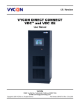
AQUATRAM 360 TM POOL LIFT
USER MANUAL
WARNING
IMPORTANT SAFETY INSTRUCTIONS
1. WARNING- TO REDUCE RISK OF INJURY, DO NOT PERMIT CHILDREN TO PLAY ON
THIS PRODUCT.
2. WARNING- DO NOT PERMIT CHILDREN TO OPERATE OR USE THIS PRODUCT.
3. SAVE A COPY OF THESE INSTRUCTIONS.
© 2011 Pentair Water Pool and Spa, Inc. All rights reserved
1620 Hawkins Ave., Sanford, NC 27330 • (919) 566-8000
10951 West Los Angeles Ave., Moorpark, CA 93021 • (805) 553-5000
AquaTRAM™ and Pentair Water Commercial Pool and Spa are trademarks and/or registered
trademarks of Pentair Water Pool and Spa, Inc. and/or its affiliated companies in the United
States and/or other countries. Unless noted, names and brands of others that may be used in
this document are not used to indicate an affiliation or endorsement between the proprietors of
these names and brands and Pentair Water Pool and Spa, Inc. Those names and brands may be
the trademarks or registered trademarks of those parties or others.
P/N 11269 Rev A - 04/18/11
1
AQUATRAMTM 360 POOL LIFT
500 LB. [227 kg] MAXIMUM CAPACITY
MANDATORY – LEAVE THIS MANUAL WITH LIFT OWNER
- READ CAREFULLYCheck entire box and inside all packing materials for parts. Before beginning
assembly, read the instructions and identify parts using the figures and parts listed in
this document. It is critical that all parts be carefully inspected by the installer prior to
installation to ensure that no damage occurred in transit and that a damaged part is
not used. If any damage occurred in transit, Pentair Water Commercial Pool and
Aquatics (“Pentair”) must be notified within three days of receipt of unit. Proper
installation cannot be overstressed, as an improper installation voids Pentair’s
warranty and may affect the safety of the user.
WARNING
IMPORTANT SAFETY INSTRUCTIONS
1. READ AND FOLLOW ALL INSTRUCTIONS. LIFT SAFETY CAN ONLY BE ENSURED IF THE LIFT
IS INSTALLED AND OPERATED PROPERLY – ACCORDING TO THESE INSTRUCTIONS.
2. WARNING- TO REDUCE RISK OF INJURY, DO NOT PERMIT CHILDREN TO USE OR
OPERATE THIS PRODUCT.
3. WARNING- DO NOT PERMIT CHILDREN TO PLAY ON THIS PRODUCT.
4. WARNING- NEVER APPLY DIRECT WATER PRESSURE TO ELECTRONIC COMPONENTS.
5. NEVER OPERATE THIS LIFT UNDER LOAD WITH NO WATER (DRY POOL).
6. SAVE A COPY OF THESE INSTRUCTIONS.
WARNING
MAKE SURE THE AREA AROUND THE LIFT IS CLEAR BEFORE OPERATING.
NEVER OPERATE THE LIFT WITH ANY PERSON WITHIN THE OPERATING RANGE
OF THE LIFT, INCLUDING ON THE DECK OR IN THE WATER. NEVER MOVE THE
LIFT DOWN WHILE OVER THE DECK. IF THE LIFT COMES INTO CONTACT WITH
THE DECK OR A WALL, RELEASE THE BUTTON IMMEDIATELY OR PRESS THE
EMERGENCY STOP BUTTON. DO NOT ALLOW CHILDREN TO OPERATE THE LIFT
WITHOUT SUPERVISION.
CHECK ALL NUTS AND BOLTS FOR TIGHTNESS AND FOR WORN PARTS
BEFORE EACH USE.
2
TABLE OF CONTENTS
PAGE
4
ASSEMBLY OVERVIEW
5
LIFT LOCATION: ADA GUIDELINES (USA)
6
APPLICATION GUIDE
7
ANCHOR INSTALLATION: RETROFIT
8
ANCHOR INSTALLATION: NEW CONSTRUCTION
9
STEP 1: LIFT ASSEMBLY
10
STEP 2: INSTALL LIFTING ARM
11
STEP 3: INSTALL CONTROL ARM
12
STEP 4: INSTALL SEAT ARM
13
STEP 5: INSTALL SEAT ASSEMBLY
14
STEP 6: INSTALL FOOTREST
15
STEP 7: INSTALL BATTERY & HANDSET CONTROL
16
LIFT OPERATION
17-18
CARE AND CLEANING
19-20
TROUBLESHOOTING GUIDE
21
PART LIST & EXPLODED VIEW
22
SEAT ASSEMBLY PARTS LIST
23-25
OPTIONS
26
WARRANTY INFORMATION
3
MAIN COMPONENTS
1. MAIN ASSEMBLY
2. LIFTING ARM
(STEP 2)
3. CONTROL ARM
(STEP 3)
4. SEAT ARM
(STEP 4)
5. SEAT ASSEMBLY
(STEP 5)
6. FOOTREST ASSY
(STEP 6)
7. 24V BATTERY PACK
(STEP 7)
8. HANDSET CONTROL
(STEP 7)
9. BATTERY CHARGER (NOT SHOWN)
ASSEMBLY OVERVIEW
STEP 1: INSTALL IN ANCHOR.
STEP 2: INSTALL LIFTING ARM.
STEP 3: INSTALL CONTROL ARM.
STEP 4: INSTALL SEAT ARM.
STEP 5: ADJUST SEAT HEIGHT.
STEP 6: INSTALL FOOTREST.
STEP 7: INSTALL BATTERY & HANDSET
CONTROL.
HARDWARE LIST
QTY.
2
2
1
1
1
5
2
DESCRIPTION
1/2” X 2-3/4” SHOULDER BOLT,
S.S.
1/2” X 3” SHOULDER BOLT, S.S.
5/16” FLAT WASHER, S.S.
5/16” NYLOCK NUT, S.S.
3/8” X 1-3/4” SHOULDER BOLT,
S.S.
3/8” FLAT WASHER, S.S.
3/8” NYLOCK NUT, S.S.
TOOL LIST
[ANCHOR INSTALLATION]
C-SAW W/DIAMOND BLADE
CHALK LINE
TORPEDO LEVEL
[LIFT ASSEMBLY]
(1) 9/16” WRENCH OR SOCKET
(1) 3/4" WRENCH OR SOCKET
(1) ALLEN WRENCH SET
UNPACKING THE SHIPPING CONTAINER: When you receive your new AquaTRAM
360 lift check your shipment carefully. Locate all main components and hardware
listed above. The tools listed will be needed to install and assemble the lift. PUT
THE 24V BATTERY ON THE CHARGER AS SOON AS POSSIBLE! The battery will
need to be charged for 24 hours before first use.
4
LIFT LOCATION: ADA GUIDELINES
Before installing the AquaTRAM 360 lift it will be necessary to select a location for the
anchor. Because of its versatility the AquaTRAM 360 lift can be installed in a wide
variety of locations, but the owner/installer should be aware of the requirements of the
Americans with Disabilities Act (ADA) with concern to lift installations. The diagram
above shows an example of an ADA compliant installation, which incorporates the
following ADA rules in order to be compliant;
•
SEAT LOCATION: In the raised position, the centerline of the seat shall be
located over the deck and 16 inches [406mm] minimum from the edge of the pool
(pool wall). The deck surface between the centerline of the seat and the pool
edge shall have a slope not greater than 1:48.
•
CLEAR DECK SPACE: On the side of the seat opposite the water, a clear deck
space shall be provided parallel with the seat. The space shall be 36 inches
[914mm] wide minimum and shall extend forward 48 inches [1219mm] from a line
located 12 inches [305mm] behind the rear edge of the seat. The clear deck
space shall have a slope not greater than 1:48.
5
AQUATRAM 360 APPLICATION GUIDE:
The AquaTRAM 360 lift has been designed for optimal flexibility, offering the user a wide
range of options for lift placement. Shown above, the AquaTRAM 360 lift is ideal for
applications where access to multiple levels (elevations) is required. The AquaTRAM
360 lift’s adjustable seat arm makes such applications easily implemented, as in this
case where the seat has been installed in one of the middle (height) positions. With the
seat in its highest position the AquaTRAM 360 lift will clear a 30” [762mm] high spa or
pool wall.
Also, because the AquaTRAM 360 lift rotates in either direction a full 360º it can be
installed close to a wall, with the wall on either side.
NOTE: IT IS RECOMMENDED THAT ANY WALL IN CLOSE PROXIMITY TO THE LIFT
BE PADDED (TO PREVENT DAMAGE TO THE LIFT OR INJURY TO THE USER
SHOULD THE LIFT BE ACCIDENTALLY OVER-ROTATED).
6
ANCHOR INSTALLATION: RETROFIT INSTRUCTIONS
The AquaTRAM 360 lift should be installed in a deck or footing with the following
specifications:
1. MINIMUM FOOTING SIZE: 4’ - 0” x 4’ - 0” x 12” THICK.
2. MINIMUM CONCRETE STRENGTH: 3000 PSI
3. REINFORCEMENT: #5 REBAR @ 10” ON CENTER (O.C.)
To ensure adequacy of an existing pool deck a 4’ – 0” square portion of the existing deck
may be saw-cut, removed and replaced with a footing as specified above. The new slab
reinforcing shall be drilled and epoxied into the existing slab as shown on the next page.
If your deck or footing does not meet these requirements please call 1-800-831-7133 for
recommendations. The anchor should be bonded (grounded) per local electrical code.
For decks that meet these requirements follow these instructions to install your anchor.
TOOLS & MATERIALS REQUIRED:
CORE DRILL
3 – 1/2” CORE DRILL BIT
MARKING PEN
EPOXY (ANCHOR ADHESIVE)*
WIRE BRUSH
AIR NOZZLE & PUMP/COMP.
HEAT GUN (OPTIONAL)
MASKING TAPE
1. Select an anchor location using the diagram below and the ADA guidelines on
page 4. Mark the center of the anchor location with a pen or marker.
2. Using a 3-1/2” diameter core-drill bit drill a 3-1/2” diameter hole at the anchor
location. Make sure to keep the bit square to the deck. Drill straight down to a
depth of at least 9”.
3. Remove plug and clean out the hole with a wire brush, and then insert an air
nozzle to the bottom of the hole and blow out the hole using a pump or
compressed air. Proper hole cleaning is essential. If the hole is wet, dry it out as
much as possible. A heat-gun may be helpful in drying out the hole.
4. Mask the top of the anchor so that no epoxy gets inside the anchor.
5. Place the anchor in the hole and ‘dry-fit’ it first to make sure the anchor will be
flush and plumb with the deck when installed. Adjust the hole as needed.
6. Install the epoxy into the dispenser and follow manufacturers’ instructions to
ensure that the epoxy is properly mixed and applied. USE ONLY THE
RECOMMENDED EPOXY AND ALWAYS FOLLOW THE INSTRUCTIONS SO
THAT FULL STRENGTH IS ACHIEVED.
7. Inject epoxy adhesive starting at the bottom until the hole is 1/3 to 1/2 full.
8. Install the anchor into the epoxy and push down until it is flush with the deck
surface. Clean off excess epoxy. Adjust the anchor to make sure it is flush and
plumb with the deck surface.
9. Let the epoxy cure for at least 24 hours before installing the lift (or where
applicable according to the manufacturers’ instructions).
*Use HILTI HIT HY-150 adhesive anchor or SIMPSON ET22 StrongTie anchor
adhesive or equivalent.
NOTE: BOND (GROUND) THE ANCHOR PER LOCAL ELECTRICAL CODE.
7
ANCHOR INSTALLATION: NEW CONSTRUCTION
For new construction a footing should be poured according to the diagram below. Again,
make sure the anchor is installed flush and plumb with the deck surface, and bond it to
the rebar grid. Again, the footing should have the following specifications:
4. MINIMUM FOOTING SIZE: 4’ - 0” x 4’ - 0” x 12” THICK.
5. MINIMUM CONCRETE STRENGTH: 3000 PSI
6. REINFORCEMENT: #5 REBAR @ 10” ON CENTER (O.C.)
NOTE: If the SLING OPTION is to be used, the maximum setback distance is 24”
(from the pool wall to the anchor).
NOTE: BOND (GROUND) THE ANCHOR PER LOCAL ELECTRICAL CODE.
8
INSTALLATION & ASSEMBLY INSTRUCTIONS:
STEP 1: INSERT MAIN ASSEMBLY INTO ANCHOR
Locate the AquaTRAM 360 MAIN ASSEMBLY and lift it from the
shipping container.
WARNING! NEVER LIFT THE MAIN ASSEMBLY USING THE
ELECTRIC LIFTING RAM AS A HANDLE! LIFT THE ASSEMBLY
FROM THE ENDS. USE AT LEAST 2 PEOPLE TO LIFT.
Insert the 2” [50mm] POST of the AquaTRAM 360 MAIN ASSEMBLY
into the deck anchor. Align the LOCKING PIN with the LOCKING
SLOT in the anchor and ease the MAIN ASSEMBLY down until it
rests on the POOL/SPA DECK SURFACE.
WARNING! MAKE SURE THE LOCKING PIN SLIDES INTO
THE LOCKING SLOT OF THE ANCHOR, AND THAT THE
MAIN ASSEMBLY SITS FLUSH WITH THE DECK SURFACE
9
STEP 2: INSTALL LIFTING ARM
Locate the LIFTING ARM and the following hardware:
•
•
•
•
•
•
(1) 1/2” x 2-3/4” SHOULDER BOLT
(1) 3/8” x 1-3/4” SHOULDER BOLT
(1) 5/16” FLAT WASHER
(1) 5/16” NYLOCK NUT
(2) 3/8” FLAT WASHER
(1) 3/8” NYLOCK NUT
Remove the shipping strap and all packing from the LINEAR
ACTUATOR. Connect the LIFTING ARM between the MAST and
the ELECTRIC LIFTING RAM as shown in the figure above.
Tighten NYLOCK NUTS (2) until snug as shown in PHOTO 2.
DO NOT OVER TIGHTEN!
10
STEP 3: INSTALL CONTROL ARM
Locate the CONTROL ARM and the following hardware:
•
•
•
(1) 1/2” x 2-3/4” SHOULDER BOLT
(1) 3/8” FLAT WASHER
(1) 3/8” NYLOCK NUT
Install the CONTROL ARM (either end) onto the MAST as
shown in the figure above. Tighten the NYLOCK NUT
until snug as shown in PHOTO 3. DO NOT OVER
TIGHTEN!
11
STEP 4: INSTALL SEAT ARM
Locate the SEAT ARM and the following hardware:
•
•
•
(2) 1/2” x 3” SHOULDER BOLT
(2) 3/8” FLAT WASHER
(2) 3/8” NYLOCK NUT
Install the SEAT ARM at the ends of the CONTROL ARM and
LIFTING ARM as shown in the figure above. Tighten the NYLOCK
NUTS until snug as shown in PHOTO 4.
DO NOT OVER TIGHTEN.
(NOTE: MAKE SURE THE SEAT IS FACING AWAY FROM THE
MAIN ASSEMBLY)
NOTE: FOR APPLICATIONS THAT UTILIZE MULTIPLE SEAT
ARMS (SUCH AS FOR A SLING SEAT OR THE SPA SEATARM) USE THIS STEP TO REMOVE AND REPLACE THE SEAT
ARM.
12
STEP 5: ADJUST THE SEAT POSITION
The SEAT ASSEMBLY will arrive attached to the
SEAT ARM adjusted to its highest position. To
adjust the SEAT ASSEMBLY to a lower position
remove the hardware as shown above. Slide the
SEAT ASSEMBLY to its desired position (in 4”
increments) and reinstall the hardware. The total
adjustment range is 16”.
DO NOT ATTACH THE SEAT ASSEMBLY ANY
LOWER THAN THIS – ALWAYS USE THE TWO (2)
SUPPLIED HEX BOLTS TO ATTACH THE SEAT
ASSEMBLY TO THE SEAT ARM!
NOTE: For most applications, such as pools with a
flat deck, the seat will be installed in its lowest
position. For applications where a wall or curb
must be cleared the seat should be installed in a
higher position. In its highest position the seat will
clear a 30” [762mm] high wall.
13
P/N 11214
P/N 11213
STEP 6: INSTALL THE FOOTREST
Locate the FOOTREST ASSEMBLY and install it on the seat as shown above. The
QUICK RELEASE PIN is attached to the SEAT ASSEMBLY with a lanyard (cable).
Pull out the pin and slide the FOOTREST ASSEMBLY into the slot and line up one
of the holes on the FOOTREST TUBE with the hole for the pin. Push the pin back
into the hole and through the hole in the FOOTREST TUBE to hold the FOOTREST
ASSEMBLY in the desired position. To re-adjust the FOOTREST simply pull out
the pin and select a new hole on the FOOTREST TUBE.
14
P/N 11211
P/N 11275
P/N 11274
STEP 7: INSTALL 24V BATTERY & HANDSET
Locate the 24V Battery, the Battery Charging unit and the Handset
Control. Charge the battery for 24 hours (see page 16 “Charging
the Battery”) then install it on the bracket above the Control Box
as shown above and in the photo to the left. Plug the Handset
Control into the Control Box as shown above and in the photo to
the left. Press firmly to make sure the plug is fully seated as
shown below.
THE LIFT WILL NOT FUNCTION IF THE HANDSET PLUG
IS NOT FULLY SEATED OR IF THE BATTERY IS NOT
PROPERLY ALIGNED.
NOT SEATED
SEATED
15
LIFT OPERATION:
Before operating the lift for the first time, the user or operator should become
familiar with the Handset Control and its functions. The figure to the left gives a
quick explanation of the four buttons and their function. For example, to move the
lift UP, press the top left button with the ▲
symbol and hold it down until the lift has reached
its desired height and then release the button.
The other buttons work in a similar fashion. In all
cases, releasing the button will cause the lift to
stop moving.
•
•
•
•
TO MOVE UP PRESS AND HOLD THE ▲ BUTTON.
TO STOP MOVING UP RELEASE THE BUTTON.
TO MOVE DOWN PRESS AND HOLD THE ▼
BUTTON. TO STOP MOVING DOWN RELEASE
THE BUTTON.
TO MOVE LEFT PRESS AND HOLD THE ◄
BUTTON. TO STOP MOVING LEFT RELEASE THE
BUTTON.
TO MOVE RIGHT PRESS AND HOLD THE ►
BUTTON. TO STOP MOVING RIGHT RELEASE
THE BUTTON.
16
USING THE “EMERGENCY STOP BUTTON” on the Control Box
On the front side of the control box is a small recessed button
marked “emergency”. If you take a pen or pencil or other pointed
object and depress the “emergency” button, this will bypass the
remote control or handset and stop the lift.
NOTE: this function will only work if there is sufficient power
in the battery, the battery is properly attached to the control
box, and the control box must be operating properly.
CHARGING THE BATTERY:
Before using any of the AquaTRAM Series Lifts for the first time the 24V Battery must be
fully charged. This will take about 24 hours on the charger. It is also recommended that
the battery be fully charged before each use. The battery can be left on the Charging
Unit overnight, or whenever the lift is not in use. DO NOT LEAVE THE BATTERY ON
THE LIFT!!!
To recharge the battery, simply grip the top of the battery and
depress the clip on the back of the battery. This will unclip the
battery from the control box bracket. The battery can then be
clipped into the wall mount charger. When the charger is plugged
in the green ON light will illuminate. When the battery is correctly
mounted to the charger, the orange CHARGE light will illuminate.
When the battery is fully charged, the CHARGE light will GO OFF
and the battery is ready to use.
WALL MOUNT CHARGER
SAFETY & MAINTENANCE INSTRUCTIONS
DO NOT PLAY ON OR AROUND THIS LIFT
1. Check the AquaTRAMTM Series Pool Lifts before each use to assure there are no
worn parts and that all hardware is properly tightened. If there are any worn
parts, replace them BEFORE using the AquaTRAMTM Series Pool Lifts. You can
call our customer service at 1-888-687-3552 to order any parts.
2. Pentair Water Commercial Pool and Aquatics lifts shall be grounded per local
codes.
3. At least ONCE A WEEK, the AquaTRAMTM Series Pool Lifts must be cleaned
with fresh water. Do not spray the AquaTRAMTM Series Pool Lifts 24v battery
unit directly with any pressure. Wipe all surfaces clean with a damp, nonabrasive cloth. When cleaning the AquaTRAMTM Series Pool Lifts, use nonabrasive soap and water. Avoid harsh chemicals and disinfectants.
4. Always read the label instructions on any cleaner carefully before applying it to a
surface.
5. The WARNING & INTENDED USE labels on the AquaTRAMTM Series Pool Lifts
must be maintained in readable fashion. If they become unreadable or faded,
please replace the label immediately. Replacement labels are available from
Pentair Water Commercial Pool and Aquatics. 1-800-831-7133.
17
CARE OF YOUR LIFT
Routine cleaning is an absolute necessity to ensure the integrity of the lift. Note that the lift
should not be stored in a pump room or in a storage room where pool chemicals are kept.
Storing the lift near pool chemicals may cause rusting and other damage to occur. Your stainless
steel lift is powder coated to protect the stainless steel from rusting. Most rusting will occur at
weld points, crevices, under gaskets, rivets or bolt heads.
The choice of a proper cleaning product is up to the consumer and there are many to choose
from. Depending on the type of cleaning and the degree of contamination (rusting), some
products are better than others. For routine cleaning the products most recommended are gentle
soaps or detergents or dilute mixtures of ammonia. For stubborn spots and stains try using soft
scrub with some brisk rubbing.
DO NOT USE POOL WATER TO CLEAN USE ONLY FRESH
WATER
If the lift is used DAILY make sure to wash the lift at the end of the day. Wash the lift off using a
mild soap and a soft cloth. Make sure to pay special attention to weld points and crevices. Do not
use a bristled brush or steel wool to clean the lift. Check that the lift is working properly and then
place the battery on the charger. It is recommended that the battery be charged after every day of
use.
If the lift is used WEEKLY follow the same steps as above. Also be sure to check all of the
contact points (terminals) for damage or corrosion. If you notice corrosion gently clean the
terminals. To clean corrosion from the terminals use a q-tip and some rubbing alcohol. If the
corrosion is particularly stubborn try using a 3M scotch brite pad, but be careful not to damage
the terminals. Apply dielectric grease to the terminals after cleaning them. This will help to
prevent further corrosion. Do not leave the battery on the lift. Always store the battery on the
charger whenever the lift is not being used.
If the lift is used MONTHLY follow the same steps as above. Also check the nuts and bolts to
make sure they are securely fastened (this is always a good idea, no matter how often or
infrequently the lift is used). Also make sure to store the battery on the charger and not on the lift.
Leaving the battery on the lift for extended periods will significantly shorten the battery’s lifespan.
If the lift is being STORED for an extended period of time follow all of the steps above. Check for
rusting at all crevice and weld points. If you notice rusting spray some WD-40 on the affected
area and take a 3M scotch-brite pad and rub briskly. Afterwards be sure to wash and rinse the lift
again with soap and water. When storing the lift make sure it is in a dry area and covered. DO
NOT STORE in or around pool chemicals.
18
TROUBLESHOOTING GUIDE
Before troubleshooting make sure the battery is fully charged.
If the lift doesn’t move when the handset button is pressed:
When you can’t get the lift to move check the following things:
1. Make sure the battery is fully charged:
A. Before charging the battery first make sure the green light on the front
of the charger is illuminated (this means that the charger is on). Then
check to make sure the silver contact points on the battery and
charger are not damaged or corroded, and that they are clean. Then
place the battery on the charger and look for the orange charge light
to illuminate on the front of the charger. When the orange light goes
off the battery is fully charged.
B.
The top green light will always be
illuminated indicating that it has power.
When charging the battery the bottom
orange light will illuminate, until fully
charged.
C. When the battery is correctly installed on the charger or control box
you should hear a “click” indicating the battery is properly seated on
the unit. Also note that when the battery is properly seated there
should not be any gaps between the battery and the control
box/charger.
Not attached properly. Note the white
bracket is in front of silver clip, which
will not allow for an electrical
connection.
Properly Attached.
Note that the white bracket is behind the
silver clip. Not allowing movement.
19
If the battery is fully charged and the lift is not moving then:
2. Check all cords:
Check that the cords are properly plugged in. Start by unplugging the remote and the
actuator cord from the control box. Once these cords are removed check the ends for
corrosion or damage. Plug the remote cord back in by lining up the raised tab on the
plug to the grooved line on the control box outlet. Note that these cords require some
force to plug them in fully. You will know they a correctly inserted when you here a
“popping sound”. The cords will be recessed into the outlet. If they are flush with the
outside of the outlet they are not plugged in fully and the lift will not function. Make
sure you do this for both cords.
NOT inserted fully.
Fully inserted.
If you have checked all the cords and the lift still doesn’t move:
3. Check the contact points:
After you have fully charged the battery and checked the cords to make sure they are
properly plugged in, check to make sure the contact points are not corroded or bent. If
the contact points are corroded take some rubbing alcohol and a q-tip and clean off the
points. After cleaning the contact points it is recommended to put some dielectric
grease on the contact points (terminals) to help ensure good electrical contact and
prevent corrosion. Then reinstall the battery on top of the control box. Make sure you
hear a “click”, which indicates that the battery is correctly seated. The lift will not work if
the battery is not seated correctly.
Silver tabs are the contact
(terminal) points.
If the lift stops moving over the water and is stuck:
4. Push the emergency button:
If the lift gets stuck out over the water use a pen or pencil tip and stick it into the emergency
button on the front of the control box to retract the lift. Note the lift will not retract if the battery is
not fully charged or if the control box is not working. The emergency button only overrides the
remote in case it has gone bad. If this does not retract the lift then chances are the remote is fine
and you either have a problem with the battery, the control box, or the cords are damaged or not
plugged in properly.
Use a pen or pencil tip to
push in the small black circle
located next to the word
emergency, on the front of
the control box.
20
ITEM # QTY.
DESCRIPTION
1
1 AquaTram 360 BASE GEAR
2
1 AquaTram 360 COVER
3
1 AquaTram 360 BASE ASSEMBLY
4
1 AquaTram 360 MOTOR PLATE
5
1 AquaTram 360 MOTOR GEAR
6
1 AquaTram 360 MAST ASSEMBLY
7
1 AquaTram 360 BOOM ARM
8
1 AquaTram 360 CONTROL ARM
9
1 AquaTram 360 SEAT ARM
10
1 AquaTram 360 SEAT BRACKET
11
1 SEAT ASSEMBLY
12
1 FOOTREST ASSEMBLY
13
1 ROTATION MOTOR, 24V
14
1 24V LEAD-ACID BATTERY
15
1 CONTROL BOX
16
1 BATTERY/CB BRACKET
17
1 HANDSET CONTROL
18
1 ELECTRIC LINEAR ACTUATOR
19
1 #8-32 X 3/16" SETSCREW, S.S.
20
3 #10-24 X 1/2" LOW PROFILE CAP SCREW, S.S.
21
4 1/4"-20 X 1" FLAT HEAD CAPSCREW, S.S.
22
8 1/4"-20 X 1" HEX BOLT, S.S.
23
20 1/4" FLAT WASHER, S.S.
24
12 1/4"-20 NYLOCK NUT, S.S.
25
1 3/8"-16 X 1-1/4" SHOULDER BOLT, S.S.
26
1 3/8"-16 X 1-3/4" SHOULDER BOLT, S.S.
27
1 3/8"-16 X 2-1/2" HEX BOLT, S.S.
28
1 3/8"-16 X 4-1/2" HEX BOLT, S.S.
29
10 3/8" FLAT WASHER, S.S.
30
6 3/8"-16 NYLOCK NUT, S.S.
31
4 1/2" X 3" SHOULDER BOLT, S.S.
32
8 1/2" X 3/4" X 3/8" FLANGE BEARING, BRONZE
33
8 1/2" X 3/4" X 1" FLANGE BEARING, BRONZE
34
2 3/8" X 1/2" X 3/8" FLANGE BEARING, BRONZE
35
1 3/8" X 1/2" X 3/8" PLAIN BEARING, BRONZE
36
2 1-1/4" X 1-3/4" X 2" PLAIN BEARING, BRONZE
37
1 3/4" FLAT WASHER, SERIES N, S.S.
38
1 3/4"-10 HEX NUT, S.S.
39
2 5/16" FLAT WASHER, S.S.
40
2 5/16"-18 NYLOCK NUT, S.S.
41
4 2" SQUARE TUBE CAP, PLASTIC
PARTS LIST:
MAIN COMPONENTS:
21
ELECTRICAL
HARDWARE
PARTS LIST: SEAT ASSEMBLY
ITEM # QTY
DESCRIPTION
1
1 SEAT BODY
2
2 SEAT ARMREST TUBE
3
2 SEAT ARMREST HANDGRIP
4
1 SAFETY BELT ASSEMBLY
5
2 1/4"-20 x 3" HEX BOLT, S.S.
6
2 1/4" FLAT WASHER, S.S.
7
1 1/4" QUICK RELEASE PIN, S.S.
8
1 LANYARD FOR QRP
9
1 SHEET METAL SCREW, S.S.
22
Options for AquaTRAM™ 360:
Adjustable Head Rest (P/N 11254)
Includes:
• Padded head rest mounted to adjustable bracket with
mounting hardware
Adjustable Chest Strap (P/N 11206)
Includes:
• Adjustable hook and loop style chest strap and
mounting hardware
Pullout Leg Rest (P/N 11208)
Includes:
• Pullout leg rest (to be factory installed)
Cycle Attachment (P/N 11207)
Includes:
• Pedal attachment and mounting hardware (cannot be
used on lifts equipped with Pullout Leg Rest 11208)
• 90° up turned hand grips for better support
Transport Cart (P/N 11253)
Includes:
• Heavy Duty lifting cart
• Boom guide
• Base lifting plate
23
Spine Board Attachment (P/N 11260)
Includes:
• Powder Coated Stainless Steel Spine Board boom
attachment
• 6’-0” Spine Board
• Optional Head Immobilizer (P/N 11261)
Gurney Attachment (P/N 11258)
Includes:
• Powder Coated Stainless Steel Gurney boom
attachment
• Pool and Spa friendly PVC gurney with vinyl
coated foam pad. Gurney to have swing down
side rails and five-position reclining headrest.
Casters for gurney are also included
Sling Arm Option (P/N 11255)
Includes:
• Sling arm boom attachment
• Sling Arm
• Sling Chains
• Sling Bars
• Polyester Mesh Sling with 500lb capacity.
24
Wheel Chair Attachment (P/N 11259)
Includes:
• Wheel Chair boom attachment
• 22” solid framed Stainless Steel Wheel
Chair. (Wheel Chair attachment to be
used ONLY with wheel chair provided)
Protective Cover (P/N 11257)
25
AquaTram™ and AquaTram™ 360
Swimming Pool Access Lift
A Division of Pentair Water Pool and Spa, Inc.
FIVE (5) YEAR LIMITED WARRANTY
AquaTram™ and AquaTram™ 360 Lift (“Lift”) have a Limited Lifetime Warranty on the frames, not including the
powder coat finish. Pentair Water Pool and Spa, Inc. (“Pentair”) also warrants to the original end user purchaser that these
Lifts, when properly installed in accordance with assembly and installation instructions, and properly used and maintained,
shall be free from defects in material and workmanship for a period of five (5) years from the date of original purchase,
provided that Pentair receives prompt notice in writing of any claim and satisfactory proof thereof, with the following
exceptions:
All electrical components, including the linear actuator shall have the following warranty coverage during the five (5)
Year Limited Warranty periods:
Year 1-2: 100% Coverage
Year 3: 60% Coverage (Customer is responsible for 40% of replacement cost)
Year 4: 50% Coverage (Customer is responsible for 50% of replacement cost)
Year 5: 40% Coverage (Customer is responsible for 60% of replacement cost)
This warranty specifically excludes reimbursement for labor to remove, repair, replace or install the Lift or component part
thereof and any return freight charges. These warranties do not cover any damages due to accident, misuse, abuse,
negligence or failure to properly maintain any Lift or component part thereof, or normal wear and tear from day to day
operations. In the event that any Lift or component part thereof are altered, repaired, or improperly installed or improperly
used by anyone without the prior written approval by Pentair, all warranties are void. IMPORTANT: AMOUNT OF
WEIGHT PLACED ON LIFT SHALL NOT EXCEED THE RATED LIFT CAPACITY (400 POUNDS FOR The
AquaTram™ Lift; 500 POUNDS for the AquaTram™ 360 Lift
To initiate a warranty claim, the owner of an AquaTram™ Lift must provide the place of purchase, in writing, with a full
description of the Lift, its serial number, the dates of purchase and installation, and the exact nature of the claim. Within
thirty (30) days after receipt of a written warranty claim by Pentair, and barring any unforeseen delays, the place of
purchase will be notified of Pentair’s decision regarding the claim.
If requested by Pentair, any Lift or component part thereof must be returned, freight prepaid, to Pentair’s designated
factory location or duly appointed distributor for inspection and/or repair or replacement. Pentair will, at its option, refund
the purchase price, or repair or replace the Lift or component part thereof, and deliver the repaired Lift or component part
thereof or replacement to the buyer of the Lift, freight prepaid to the destination provided for in the original order. Lift or
component part thereof returned to Pentair for which Pentair provides replacement under this limited warranty shall
become the sole property of Pentair.
A new warranty period shall NOT be established for the repaired or replaced Lift or component part thereof. Such Lift or
component part thereof shall remain under warranty only for the remainder of the original warranty period on the original
Lift purchased.
This written limited warranty constitutes the final, complete and exclusive statement of warranty terms. No person or
organization is authorized to make any other specific or implied warranties or representations on behalf of Pentair.
THE WARRANTIES SET FORTH HEREIN ARE IN LIEU OF ALL OTHER WARRANTIES, EXPRESSED OR
IMPLIED, WHICH ARE HEREBY DISCLAIMED AND EXCLUDED, INCLUDING WITHOUT LIMITATION ANY
WARRANTY OF MERCHANTABILITY OR FITNESS FOR A PARTICULAR PURPOSE OR USE.
THE SOLE AND EXCLUSIVE REMEDIES FOR BREACH OF ANY AND ALL WARRANTIES WITH RESPECT TO
THE LIFT OR COMPONENT PART THEREOFSHALL BE LIMITED TO REPAIR OR REPLACEMENT AT
PENTAIR’S DESIGNATED FACTORY LOCATION, OR DULY APPOINTED DISTRIBUTOR, OR SUCH OTHER
LOCATION AT PENTAIR’S SOLE OPTION. IN NO EVENT SHALL PENTAIR’S LIABILITY EXCEED THE
ENTIRE AMOUNT PAID TO PENTAIR BY THE ORIGINAL PURCHASER FOR THE LIFT OR COMPONENT
PART THEREOF.
IN NO EVENT SHALL PENTAIR BE LIABLE FOR ANY INCIDENTAL, CONSEQUENTIAL, SPECIAL,
INDIRECT, PUNITIVE OR EXEMPLARY DAMAGES OR LOST PROFITS FROM ANY BREACH OF THIS
LIMITED WARRANTY OR OTHERWISE.
Pentair Water Commercial Pool and Aquatics™, A Division of Pentair Water Pool and Spa, Inc.
1620 Hawkins Ave., Sanford, NC 27330
1351 Route 55, LaGrangeville, NY 12540
26
PENTAIR WATER POOL AND SPA, INC.
1620 Hawkins Ave. Sanford, NC 27330 - 10951 W. Los Angeles Ave. Moorpark, CA
93021
- Phone 800-831- 7133
- Fax 800-284-4151
P/N 11269 Rev A
27