1
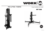
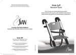
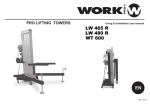
LW
LW
LW
LW
LW
LW
LW
LW
LW
330
135
142
150
155
185
255
265
290
R
R
R
R
R
R
R
R
Equipson, S.A.
www.equipson.es
[email protected]
ENG
LIFTING TOWERS/INSTALLATION AND USER MANUAL
ANNUAL TEST (passing the fourth year)
Date
Checked by
Signature
Tested elements and conclusions
ANNUAL TEST (passing the fourth year)
Date
Checked by
Signature
Tested elements and conclusions
ANNUAL TEST (passing the fourth year)
Date
Checked by
Signature
Tested elements and conclusions
INSTALLATION AND USER MANUAL
BGV C1, TESTS & CHECKS
MODEL
SERIAL NUMBER
INITIAL CHECK (First year)
Date
Checked by
Signature
Tested elements and conclusions
FOUR YEARS TEST
Date
LIFTING TOWERS
Checked by
Signature
Tested elements and conclusions
LW
LW
LW
LW
LW
LW
LW
LW
LW
330
135
142
150
155
185
255
265
290
R
R
R
R
R
R
R
R
INSTALLATION AND USER MANUAL
LIFTING TOWERS
BGV C1 REGULATION, Explanation
BGV C1 is a regulation for Staging and Production Facilities for the
Entertainment Industry. Lifting and rigging equipment is just part of this
standard and cover structures and other technical matters.
Adopting
BGV C1 is entirely voluntary (except in Germany) but its adoption is
generally required by insurance companies and therefore it has effectively
become an industry standard.
The application of this standard over lifting towers is vital due
to in theatres, stages, etc. are used to move loads over performers
and, in some cases, above spectators, representing a potential falling risk.
BGV C1 REGULATION, Application fields
This standard is orientated in two ways:
By one side, the lifting towers adopt designs and materials in order to
achieve a high security degree in magnitudes like load supported,
balance, friction resistance, etc.
So a WORK® lifting tower BGV C1 certified ensures the customer
that has passed strict test during its design, materials choice or
load and effort verifications.
By other side, in order to achieve an optimum operation with these
units, is recommended as much a responsible use of the unit,
complying basic rules like maximum load accepted or tower balance
as maintenance periodic, which must be carried by expert technicians,
checking the good state of the steel cable and winch, operation of
the safety bolts and folding/unfolding of the entire profile system.
INSTALLATION AND USER MANUAL
LIFTING TOWERS
CONFORMITY DECLARATION
The described Truss-Lifts meets all the requirements specified in the Machinery Directive
98/37/EC of 22.96.98 (OJ nº L 207 of 23.07.98, p.1)
Applicant
:
EQUIPSON, S.A
Address
:
Avda. El Saler, 14 Pol. Industrial L´Alteró
46460 SILLA - Valencia (Spain)
Representative
:
EQUIPSON, S.A
Address
:
Avda. El Saler, 14 Pol. Industrial L´Alteró
46460 SILLA - Valencia (Spain)
Description
:
INTRODUCTION
1
SPECIFICATIONS
2
TECHNICAL FEATURES
3
ENGLISH
CAUTIONS BEFORE LIFT
5
ASSEMBLY AND USE INSTRUCTIONS
11
LIFTING PROCESS
13
LIFT DOWN AND FOLDED PROCESS
19
USING ADVICE
20
ACCESSORIES
21
CONFORMITY DECLARATION
23
BGV C1, EXPLANATION & TEST
24
Lifts for Truss Systems
WORK®
LW 330
WORK®
LW 135R
WORK®
LW 142R
LW 155R
WORK®
LW 150R
WORK®
LW 185R
LW 265R
WORK®
WORK®
WORK®
LW 255R
LW 290R
WORK®
Juan José Vila
(Product Manager)
April 21, 2007
The test report was carried out from the submitted type-samples of a product in
conformity with the specification of the respective standards. The certificate holder has
the right to fix the CE-mark on the product complying with the inspection samples.
ACCESSORIES
INTRODUCTION
®
Thanks you to get a WORK product. We hope to satisfy needs.
Accessory
®
Truss adapter.
400 x 600 mm.
The WORK lifters enjoy of the highest reputation, thanks to carefulness in the
manufacturing and quality control in each spare part, such as the engineering
which designed systems allowing its perfect working.
Lifting Tower
AW 19
AW 20
LW 255R
LW 265R
AW 30
LW 290R
®
In a WORK lifter, you would find:
Accessory
SAFETY: Considering that the lifting towers are used in situations where the
human being takes part, the security has been our main target.
For this, BFV C1 (GUV 6.15), BGG812 (GUV 66.15) certification
obtained by our lifters give us a guarantee.
Support bar for truss.
Fixed width.
Bar lenght: 250 mm.
STRENGTH: Manufactured with best materials, it robustness avoids any
problem of weight and transport, and resists any inclemency situation.
QUALITY: Every piece, has been suffered a very strict quality control on each
process and assembly.
AW 1
Accessory
Lifting Tower
AW 1
LW 185R
LW 142R
LW 150R
LW 155R
ACCESSORY INSERTION (Procedure)
EASY CARRIAGE: Though for live events where the professional disposes of
few time to carry on and fitting up.
ATTENTION
Lifting Tower
LW 330
LW 135R
1. Use the correct accessory according the insertion diameter (see closed table)
2. Unscrew the Allen type screw on the end piece of the lifting tower.
3. Insert the accessory and fasten firmly the Allen screw in order to ensure the accesory
into the lifting tower.
VERY IMPORTANT
Before using the lifting tower, read carefully this owner manual.Handle
none element if you are not sure of its fuction.
Unscrew the Allen type screw on the end
piece of the lifting tower and insert the
accessory fastening the screw until the
accessory will be firm.
Let revise the lifter every year to your nearest distributor.
In the case you need change any element of the lifter, only use original WORK
spare parts. Only these spare parts guarantee a good working of this product.
®
®
All repairs of the lifter can be realised by a WORK authorized establishment.
If you have any doubt, please contact us through the nearest distributor.
INSTALLATION AND USER MANUAL
INSTALLATION AND USER MANUAL
LW 330/135R/142R/150R/155R/185R/255R/265R/290R LIFTING TOWERS
1
LW 330/135R/142R/150R/155R/185R/255R/265R/290R LIFTING TOWERS
22
ACCESSORIES
SPECIFICATIONS
LW 330
LW 135R
AW 135
Accessory
Support bar for truss.
Fixed width.
Bar lenght: 250 mm.
Lifting Tower
LW 330
LW 135R
AW 235
Accessory
Lateral support bar
for truss.
Adjustable width.
Bar lenght: 212 mm.
LW 142R
LW 150R
LW 155R
LW 142R
LW 150R
LW 155R
Lifting Tower
LW 330
LW 135R
AW 335
LW 142R
LW 150R
LW 155R
Accessory
Lifting Tower
AW 135
AW 155
AW 140
AW 150
LW 185R
LW 255R
LW 265R
LW 290R
Accessory
AW 235
AW 255
AW 240
AW 250
Lifting Tower
LW 185R
LW 255R
LW 265R
LW 290R
Accessory
Lifting Tower
AW 335
AW 355
AW 340
AW 350
LW 185R
LW 255R
LW 265R
LW 290R
MAX
LOAD
(KG)
Lifting Tower
LW 330
LW 135R
Parallel truss support
AW 10
LW 142R
LW 150R
LW 155R
Twin lateral support
for truss.
Fixed width.
598 x 200 mm.
Lifting Tower
LW 330
LW 135R
AW 435
LW 142R
LW 150R
LW 155R
BASE
(M)
HEIGHT
(M)
BASE
(M)
WEIGHT
(KG)
35
3,3
1,3 x 1,3
1,3
0,15 x 0,15
35
3,5
1,77 x 1,77
1,94
0,38 x 0,38
24
LW 142 R
100
25
35
4,05
1,77 x 1,77
1,60
0,36 x 0,36
28
20
LW 150 R
100
25
35
5
2x2
1,89
0,40 x 0,40
30
LW 155 R
150
25
35
5,3
2x2
1,72
0,37 x 0,37
45
LW 185 R
190
20
35
5,3
2x2
1,70
0,50 x 0,50
70
LW 255 R
220
25
55
5,3
2x2
1,75
0,46 x 0,46
90
LW 265 R
220
25
40
6,5
2x2
1,84
0,46 x 0,46
99
LW 290 R
290
25
50
6,6
2x2
1,81
0,46 x 0,46
135
COMPOS.
Ø
(mm)
LW 330
LW 185R
LW 255R
LW 265R
LW 290R
LW 150 R
LW 155 R
LW 185 R
LW 255 R
LW 290 R
WEIGHT/Mt ROLL.
(N / mm2) (KN - KP)
REDUCT.
(KG/M)
Ø
BOBBING
( mm.)
0,055
38
2.5 : 1
4
19.6 - 1990
4
19.6 - 1990
0,055
4
19.6 - 1990
0,055
4
1770
19.6 - 1990
0,055
4
19.6 - 1990
0,055
6
19.6 - 1990
0,125
6
19.6 - 1990
0,125
19.6 - 1990
0,125
28.8 - 2930
0,187
6
7 x 19
WINCH
CABLE
RESIST. LOAD
7
RANGE
38
2.5 : 1
40
2.5 : 1
38
2.5 : 1
40
2.5 : 1
48
3.75 : 1
48
3.75 : 1
48
3.75 : 1
48
3.75 : 1
Standards and Regulations applied on winches incorporated on each lifting tower.
MODEL
STANDARDS AND REGULATIONS
MODEL
STANDARDS AND REGULATIONS
LW 330
DIN 3060 / VGB 8 / TÜV 9591009.02
LW 185 R
DIN 3060 / VGB 8 / TÜV 9591009.02
LW 135 R
DIN 3060 / VGB 8 / TÜV 9591009.02
LW 255 R
DIN 15020 / VGB 1 / VGB 8
LW 142 R
DIN 3060 / VGB 8 / TÜV 9591009.02
LW 265 R
DIN 15020 / VGB 1 / VGB 8
LW 150 R
DIN 3060 / VGB 8 / TÜV 9591009.02
LW 290 R
DIN 15020 / VGB 1 / VGB 8
LW 155 R
DIN 15020 / VGB 1 / VGB 8
INSTALLATION AND USER MANUAL
INSTALLATION AND USER MANUAL
LW 330/135R/142R/150R/155R/185R/255R/265R/290R LIFTING TOWERS
HEIGHT
(M)
25
AW 10
AW 13
AW 12
AW 20
LW 185R
LW 255R
LW 265R
LW 290R
(mm)
25
LW 142 R
AW 435
AW 455
AW 440
AW 450
INSERT.
(KG)
100
Lifting Tower
Lifting Tower
LOAD
FOLDED TOWER
100
Accessory
Accessory
DISPLAYED TOWER
LW 135 R
LW 265 R
Accessory
Ø
LW 330
LW 135 R
Accessory
MIN
CROSSED TO RIGHT
Support bar for truss.
Adjustable width.
Bar lenght: 600 mm.
Lifting Tower
6 x 19 +1 STANDARD
(GALVANIZED)
Accessory
21
LW 330/135R/142R/150R/155R/185R/255R/265R/290R LIFTING TOWERS
2
USING ADVICE
TECHNICAL FEATURES (Only LW 330 model)
- Telescopic tower for lifting vertical load.
- System covers by an electrolytic bath of zinc.
- Telescopic tower composed of 3 sections extensible by means of an iron cable of
high resistance to the traction, drives by pulleys and auto lubricated bearing.
- LW 330 lifting tower has been designed for the transport in whatever way. Its exclusive
folded system allows to reduce its dimensions to 1,3 meters height, being able to be
carried in cars and small vehicles. Moreover its 20 kg becomes it in an ultraportable
tower.
If the height you desire to get and it is not the top, distribute the extension of all
sections equitably to avoid an unbalance when you lift up the first section until
its top and left the rest without lifting up.
Bolts used in WORK® LW 330
WRONG
RIGHT
wrong
distribution
of sections
Uniform
distribution
of sections
Bolt for telescopic system
Bolt for folding/unfolding
leg system
When the load is largely plac ed, it is recommendable to us e 2 lifters so the load
is distributed and balanced too.
Its folded system consist of 4 legs, two of them dispose of extensible mechanism
in order to correct whatever light inclination
For getting optimize and efficiency working of this lifter and a longer using,
please consider following recommendations:
Check periodically the condition of the wir e, unrolling the reel fully and watch
over that the filament is not unthreaded, breach or flatten.
In the case you detect any of these probl ems, contact with your distributor to
proceed of the change.
Lubricate periodically the toothed wheel of the winch and lifting bearings of each
section, as the lifting mechanism of the legs.
NOTICE: Use this function only in case to compensate a light inclination NEVER
unfold these leg if the inclination of the surface can constituate a fall
down risk.
NEVER LUBRICATE THE BRAKE MECHANISM OF THE WINCH, IT
DISPOSES OF SPECIAL LUBRICATE SYSTEM AND THE ADDITION OF
ANY OTHER COMPONENT IN THE MECHANISM, CAN SERIOUSLY
AFFECT ITS WORKING.
INSTALLATION AND USER MANUAL
INSTALLATION AND USER MANUAL
LW 330/135R/142R/150R/155R/185R/255R/265R/290R LIFTING TOWERS
3
LW 330/135R/142R/150R/155R/185R/255R/265R/290R LIFTING TOWERS
20
TECHNICAL FEATURES (100R/200R series)
LIFT DOWN AND FOLDED PROCESS
- Telescopic towers for lifting vertical load.
- System covers by an electrolytic bath of zinc.
- Telescopic tower composed of diverse iron sections extensible by means of an iron cable of
high resistance to the traction, drives by pulleys and auto lubricated bearing.
ATTENTION!! VERY IMPORTANT
Look after the load while you go down the lifter. Do not be in hurry when you lift
down the load, be carefully.
The lifting down process is exactly the contrary to the lifting up. So, we start to unblock all the lowest
bolts of the lifting tower and turn on softly the crank in the anticlockwise way and check the load for
possible oscillations.
MODEL
LW 135 R
LW 142 R
LW 150 R
LW 155 R
LW 185 R
SECTIONS
2
3
3
4
4
MODEL
LW 255 R
LW 265 R
LW 290 R
LW 330
SECTIONS
4
5
5
3
Unblock first the lower
trigger until its section
lift down completely,
then block it and unblock
the next upper, repeting
the process untill all
sections are folded.
LW 135R LW 142R
LW 150R
LW 155R
LW 185R (*)
LW 255R
LW 265R
LW 290R
All mobile system is fixed through safety bolts. To apply them, pull the ring and turn it,
the intern spring will proceed to liberate the plunger.
Bolts used in WORK® lifting towers
ATTENTION!! VERY IMPORTANT
NOTE: When you lift down the lifter, if any of sections will not fully go down, stop
to rotate the winch because the system will be rigidity and it would bring about a
sudden descent of this section.
To avoid this, rotate the crank in the opposite sense as if you lift down and
insure that the bolt of this section is unblocked, so repeat the lifting down
process.
In the case the problem persists, look a fter that the lifter has a minimum load to
easy the descent of sections.
(*) LW 185 R with the same
number of sections than
LW 255 R but different bolt
type
INSTALLATION AND USER MANUAL
INSTALLATION AND USER MANUAL
LW 330/135R/142R/150R/155R/185R/255R/265R/290R LIFTING TOWERS
19
LW 330/135R/142R/150R/155R/185R/255R/265R/290R LIFTING TOWERS
4
TECHNICAL FEATURES (100R/200R series)
LIFTING PROCESS (Common process for all models)
- Extreme sides of legs are fitted with stabilizers for adjustable height.
- Turn on the handle to get a perfect balance of the lifter.
After fixing the section in the desired position with the bolt, unblocked the
following section in necessary case and go on lifting up.
Important: Turn on circularly stabilizers handle carefully when you want to balance the
the lifter with the vial.
It means, step by step and controlled that the verticality is right, not fully turn on one
stabilizer and cause the unbalance and the fall of the lifter.
FOR A SAFETY BLOCKING, FIX TRIGGERS TO CORRESPONDING
HOLES
ATTENTION!! VERY IMPORTANT
Once finished the lifting process, insure that all bolts are in blocked position.
NOTE: If in the process of lifting the tower, section is stayed blocked, do not
force the crank. If you can not release the bolt, you should rotate the winch in
the contrary way meanwhile that you draw out the bolt until you fully unblock.
Water level allows adjusting the verticality of the mast lifter.
Fitted with wheels for its transport, depending in the model, wheels can be situated in
different positions.
INSTALLATION AND USER MANUAL
INSTALLATION AND USER MANUAL
LW 330/135R/142R/150R/155R/185R/255R/265R/290R LIFTING TOWERS
5
LW 330/135R/142R/150R/155R/185R/255R/265R/290R LIFTING TOWERS
18
CAUTIONS BEFORE LIFT (LW 330 only)
LIFTING PROCESS (Common process for all models)
Once the lifter is fixed firml y on the floor, the lifter is now ready for its lifting.
1. Place the tower over a stable surface
If the ground presents some inclination, level it with the
extension mechanism placed in two of the legs.
1. The first that we would control, it is all safety bolts are in blocked position (1).
In the case that one of them is in unblocked position (2), pass to the blocked
position (1).
- The liberated section, lifts thanks to the pulley system.
The winch auto brake mechanism also allows to stop all the process
without producing the sudden fall of the section if this has not fixed.
NOTICE: Use this function only in case to compensate
a light inclination. NEVER unfold these leg if
the inclination of the surface can constituate
a fall down risk.
-The sections dispose inside them, holes where they are lodged the liberated bolt and
maintain the lifter fixed in an end position or several intermediaries.
When you get these positions, turn on the trigger for a perfect fixation of the
section.
BLOCKED (1)
UNBLOCKED (2)
2. Beware the movement of the inferior mechanism during the folded and
unfolded process. Could be dangerous put hands or finger in its way.
Trigger blocked when
the tower is lifted to
choice height
Trigger unblocked
during lifting process
2. Before lifting the lifter, you should understand the working of the system.
When you turn the crank as it is indicated in the drawn, the pulley system will
work on all sections, lifting “in theory” the lightest however it is not 100% reliable.
The only form to lift the desired sect ion is UNBLOCKING SOLELY the bolt
which jams this section.
Warning
3. Block the safety pin when the tower has been unfolded until the chosen
position
IMPORTANT
Rotation Way
The cable must always maintain
the strain in order to make easy
the lifting process.
INSTALLATION AND USER MANUAL
INSTALLATION AND USER MANUAL
LW 330/135R/142R/150R/155R/185R/255R/265R/290R LIFTING TOWERS
17
LW 330/135R/142R/150R/155R/185R/255R/265R/290R LIFTING TOWERS
6
LIFTING PROCESS (Common process for all models)
CAUTIONS BEFORE LIFT (100R/200R series)
Place the lifter on a stable surface.
Blocked bolt
(This section does not lift)
Unblocked Bolt
(Lift only the upper section)
Blocked bolt
(This section does not lift)
Trigger unblocked
Place in the rear side
(To lift the upper section only)
Blocked bolt
(This section does not lift)
3. The right form of lifting is, first the
parts.
upper section, after t he successive lower
Check that the automatic bolt of the legs is correctly fixed to the base of
the lifter and the trigger is well insured.
1st Bolt to unblock
Raise the upper section
2 nd Bolt to unblock
Raise the upper section
3 rd Bolt to unblock
Raise the upper section
Balance the lifter in vertical position thank to the vial in the mast.
Turn clockwise the handle of stabilizer until adjusting the right level in
the case you want to correct the level position.
4. Now you can start lifting up the lifter. When the raising section it is near the desired height,
release the bolt.
Then, go on lifting up softly until the bolt is introduced into the section. In this moment, if you
desire to go on with the lifting up, unblock the corresponding bolt to the next section.
Waiting for the
coincidence fixation
hole, release the bolt.
Once the desired height section is almost reached,
fix the bolt and the section
will be automatically blocked.
INSTALLATION AND USER MANUAL
INSTALLATION AND USER MANUAL
LW 330/135R/142R/150R/155R/185R/255R/265R/290R LIFTING TOWERS
7
LW 330/135R/142R/150R/155R/185R/255R/265R/290R LIFTING TOWERS
16
CAUTIONS BEFORE LIFT (Common cautions for all models)
LIFTING PROCESS (LW 290 R only)
Block distinct section of the lifter with safety bolts, it is very important to do
it because in the case of break down in the wire, this precaution allows to
jam all sections and avoid the fall of loaded sections consecutively.
In that moment the first section will lift and the trigger will be unblocking slowly
The distance “D” increase until a hole
will be in front of trigger, in that moment
the trigger is blocked (D=0) and tower
secure.
We can continue with the process and
the behaviour of the trigger will be the
same until to reach the desired height
or all section will be unfolded.
Before placing the load in the adecuated lifting Accessory, check that the load
exceed the minimum stipulated for each tower.
A lower load applied than minimun one could make more difficult the descent
load process.
KG
>
= MINIMUM LOAD
D
Now, the lower section will lift with the same way. Remember not to unblock none trigger
during this process.
When you lift the lifter, notice possible
Objects or cables which there are
around the lifter
ATTENTION!! VERY IMPORTANT
6. If you place the lifter outdoor, insure
with ropes for avoiding possible
swinging due to the wind.
DANGER!!!
Electric conduction
Once finished the lifting process, insure that all bolts are in blocked position.
NOTE: If in the process of lifting the lifter, section is stayed blocked, do not
force the crank. If you can not release the bolt, you should rotate the winch in
the contrary sense meanwhile that you draw out the bolt until you fully unblock.
INSTALLATION AND USER MANUAL
INSTALLATION AND USER MANUAL
LW 330/135R/142R/150R/155R/185R/255R/265R/290R LIFTING TOWERS
15
LW 330/135R/142R/150R/155R/185R/255R/265R/290R LIFTING TOWERS
8
CAUTIONS BEFORE LIFT (Common cautions for all models)
LIFTING PROCESS (LW 290 R only)
-The sections dispose inside them, holes where the liberated bolt is lodged maintain the lifter
fixed in an end position or several intermediaries. These holes have elliptical shape in order
to support better the weight loaded.
7. DO NOT REMAIN UNDER THE LIFTER ONCE IT IS FITED
Holes with
elliptical
shape
8. Do not move the lifter once it is lifted and loaded
When you turn the crank as it is indicated in the drawn, the pulley system will
work on all sections, lifting “in theory” the lightest however it is not 100%
reliable. The section lifting order depend on the friction between them. Normally it occurs
with the upper section , which is the first to be elevated, but if the load is distributed in different
way, the liftered section could be another. For this reason is very importan to distribute the load
in an uniform way.
9. Please, insure an uniform distribution of the load in order to avoid a “lever”
effect or the fall of the lifter.
(The possible solution could be the using of 2 lifters)
KG
KG
KG
Rotation Way
KG
KG
INSTALLATION AND USER MANUAL
INSTALLATION AND USER MANUAL
LW 330/135R/142R/150R/155R/185R/255R/265R/290R LIFTING TOWERS
9
LW 330/135R/142R/150R/155R/185R/255R/265R/290R LIFTING TOWERS
14
CAUTIONS BEFORE LIFT (Common cautions for all models)
LIFTING PROCESS (LW 290 R only)
LW 290 R disposes of a new security block system, that allows to fix and secure the
lifting tower in whatever position.
This new system offers an easy operation, because you can save the work to unblock
and block the trigger during the lifting process. Now, blocking all triggers, it is possible
to lift the tower for an easy way.
Once the lifter is fixed firml y on the floor and t he bubble of the water level in the
centre, after follow all previous steps, the lifter is now ready for its lifting.
10.Verify the condition of the winch and the wire.
1. The first that we would control, it is ALL SAFETY BOLTS ARE IN BLOCKED POSITION.
In the case that one of t hem is in unblocked position, pass to the blocked position.
11. DO NOT overload the lifter.
- The liberated section, lifts thank to the pulley system.
The mechanism of auto brake in the winc h also allows stopping all the process
without producing the sudden fall of the section if this has not fixed.
KG
KG
BLOCKED
12. DO NOT lubricate the brake system of the winch the mechanism could be
lost efficiency.
OI
L
13. DANGER. THE LIFTER IS NOT DESIGNED TO LOAD PEOPLE.
Avoid this
situation
UNBLOCKED
IMPORTANT: During all lifting process the triggers
MUST NOT BE UNBLOCKED
INSTALLATION AND USER MANUAL
INSTALLATION AND USER MANUAL
LW 330/135R/142R/150R/155R/185R/255R/265R/290R LIFTING TOWERS
13
LW 330/135R/142R/150R/155R/185R/255R/265R/290R LIFTING TOWERS
10
ASSEMBLY AND USE INSTRUCTIONS
ASSEMBLY AND USE INSTRUCTIONS
LW 330 only
LW 100R/200R series
- Place the lifter over a plate and balance surfaces
ATTENTION!! VERY IMPORTANT
It is of vital importance for your safety that you carefully this owner
manual before manipulating the telescopic lifter.
1. Situate the lifting tower over a level and steady surface. If the ground presents some
inclination, level it with the extension mechanism placed in two of the legs. In order to
unfold the tower, unblock the safety pin. The inferior mechanism will move upside,
unfolding the legs.
- Take out legs from the transport lodging, turn on the trigger and insert legs until its right position,
turn on again the trigger insuring the firmness of the assembly.
Tower unfolded
Legs housing
Safety trigger for
legs
Unblock this safety pin
in order to unfold the
tower
- Adjust the stablility of the lifter with the handle of each leg, until reaching centre the
bubble of the water level.
(NOTE: FOR A HIGHER STABILITY, REGULATE THE HEIGHT OF LEGS UP
TO WHEELS LEFT TO BE IN CONTACT WITH THE FLOOR)
2. If the ground presents some inclination, level it with the extension mechanism
placed in two of the legs.
3. Place the load on the tower with the appropiated lifting accessory without overpassing the
maximum weight specified by the manufacturer.
- Place the load over the fitting support for each type of lifter , without overload the maximum
weight specifies.
INSTALLATION AND USER MANUAL
INSTALLATION AND USER MANUAL
LW 330/135R/142R/150R/155R/185R/255R/265R/290R LIFTING TOWERS
11
LW 330/135R/142R/150R/155R/185R/255R/265R/290R LIFTING TOWERS
12