1
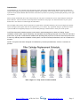
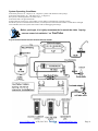
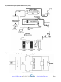
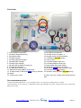
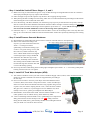
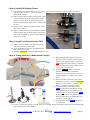
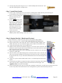
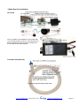
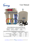
iSpring Reverse Osmosis Water Filter Systems
USER’S MANUAL
(Under-sink 5-stage, 6-stage, 7-stage RO systems)
Version 2014-3
Copyright ©2005-2014 ISPRING WATER SYSTEMS, LLC. All rights reserved.
Warranty Registration
We provide 30-day money back guarantee, 1 year Manufacture Warranty and lifetime tech
support to all products. However, we do not have the order information from the vendors other
than 123Filter.com. The easiest way to activate the warranty is to forward your order confirmation
email to [email protected], along with your comment; or if you prefer, please fill out and mail
the form below. Please remember, we love to help customers. If you have any question or concern
about our products, please don’t hesitate to call or email us. We will do all we can to make your
purchase a 5-star experience.
If you are happy with our product and service, please show your support by writing a product
review on Amazon, even with a single line. It takes you just a minute, but means a lot to us. Thank
you!
iSpring Warranty Registration Form
Your Name:
Your E-Mail:
Your Phone:
Order#:
Model#:
Order Date:
Reviewer ID:
Notes:
How to reach us
Local / International: 678-261-7611
Fax: 678-530-1070
Office Hours: Monday-Friday 9:00 a.m. - 5 p.m. EST
Technical Support Hours: Monday-Friday 9:00 a.m. - 5:00 p.m. EST
Mailing Address:
iSpring Water Systems
3020 Trotters Pkwy
Alpharetta, GA 30004 USA
www.123filter.com | (678) 261-7611
[email protected]
Page 1
Limited Warranty
This Limited Warranty extends to the original purchaser of the system only. This warranty covers all
Manufacturer-supplied items only that prove to be defective in material, workmanship or factory preparation. This
warranty covers parts only; all labor is excluded from this warranty, including, but not limited to, services related to the
removal, replacement, installation, adjustment, maintenance and/or repair of the unit or its components items.
excludes all non-Manufacturer labor required for any servicing of the unit, including, but not limited to, servicing
related to installation, adjustment, maintenance and repair of the unit. This warranty applies only for the first full
calendar year from date of purchase. The following items are excluded from this warranty: membranes, filters, O-rings,
and all other parts or components that require regular replacement as a result of ordinary usage.
Disclaimers: This Limited Warranty applies only if the system is installed, used and maintained in compliance with all
instructions and requirements enclosed with the system. This warranty will be void for failure to observe the following
conditions:
1. The system is to be used with potable water supply only.
2. Feed water pressure to the unit is no less than 45 PSI (30 PSI for systems with built-in booster pump) and no greater
than 80 PSI.
3. The system is to be used on water supplies with chlorine concentrations of 1.0 mg/L (ppm) or less.
4. Feed water temperature to the unit must be no less than 40°F and no more than 100°F.
5. Total dissolved solids (TDS) in feed water must be less than 750 mg/L (ppm).
6. Feed water must have a pH between 4 and 8.
7. Turbidity must be less than 1.0 NTU.
8. SDI must be less than 5.
9. Feed water must be completely free of iron, manganese or hydrogen sulfide.
Do not use with water that is microbiologically unsafe or of unknown quality without adequate disinfection before or
after the system.
The Manufacturer does not know the characteristics of your water supply. The quality of water supplies may vary
seasonably or over a period of time. Your water usage may vary as well. Water characteristics can also change if the
drinking water appliance is moved to a new location. The Manufacturer assumes no liability for the determination of
the proper equipment necessary to meet your requirements, and we do not authorize others to assume such obligation
on our behalf.
This Limited Warranty does not cover any Manufacturer-supplied items that are defective as a result of the use of
improper parts, equipment or materials. This warranty does not cover alterations or modifications of the unit, or failure
of a unit caused by such alterations and modifications.
This Limited Warranty does not cover malfunctions of the unit due to tampering, misuse, alteration, lack of regular
maintenance, misapplication, fouling due to hydrogen sulfide, manganese or iron, scaling from excessive hardness,
turbidity greater than 1.0 NTU, Silt Density Index (SDI) greater than 5.0 SDI, or excessive membrane hydrolysis due
to chlorine levels in excess of 1.0 mg/L (ppm). In addition, damage to the unit due to fire, accident, negligence, act of
God, or events beyond the control of the Manufacturer are not covered by this warranty.
Incidental and Consequential Damages Limitation: The Manufacturer will not be responsible for any incidental or
consequential damages as a result of the failure of this unit to comply with express or implied warranties or any defect
in the unit, including but not limited to, lost time, inconvenience, damage to personal property, loss of revenue,
commercial losses, postage, travel, telephone expenditures, or other losses of this nature. In case some states do not
allow the exclusion or limitation of incidental or consequential damages, you may choose to return the system. If you
choose to keep it, you insist this exclusion STILL apply to you.
Owner’s Warranty Responsibilities: As a condition of this Limited Warranty, the owner must ensure periodic
maintenance of the system is performed as described in the literature enclosed with the system. Neglect, improper
maintenance, abuse, modification or alteration of the unit will invalidate this Warranty. Should your unit develop a
defect or otherwise fail to perform in accordance with this warranty, you should contact the retailer from whom the
product was originally purchased.
Implied Warranties: The implied at-law warranties of merchantability and fitness for a particular purpose
shall terminate on the date one year after the date of purchase. Note: in case some states do not allow
limitations on how long an implied warranty lasts, you may choose to return the system. If you choose to
keep it, you insist the above limitations STILL apply to you.
www.123filter.com | (678) 261-7611
[email protected]
Page 2
Introduction
Congratulations on your purchase of the iSpring RO system. Featuring a multiple-stage filtration process, the Reverse
Osmosis technology incorporates polypropylene sediment (PP), granular active carbon (GAC), carbon block (CTO) and
optional Calcite mineral alkaline filter and Ultra-Violet filter to produce crisp-tasting, bottled-quality drinking water right
at your home.
When properly maintained, this system will provide you with years of trouble-free service. Please keep this manual for
future reference. The next sections contain important information on the proper care and maintenance of your system.
Please take a few minutes to read through this information.
The cartridges in RO system must be replaced on a regular basis to maintain efficiency and to ensure high water quality.
These cartridges work together and must be replaced every 6-12 months. Any significant change in performance of the
system should be investigated promptly to avoid secondary damage or deterioration to other parts of the system.
CAUTION: Improperly installed systems could result in water damage due to leaks or flooding. Proper
installation of this system requires familiarity with standard sink plumbing and proper use of common hand and
power tools. If you are not familiar with standard sink plumbing and proper use of common hand and power tools
or have any difficulty with the installation of this system, consult a licensed professional, such as a contractor or
plumber.
NOTE: This system has been designed for installation by licensed professionals, such as a contractor or
plumber.
Note: stage 6 or 7 only exists in certain models
www.123filter.com | (678) 261-7611
[email protected]
Page 3
System Operating Conditions
Feed water pressure: 45 – 80psi (or 30 – 80psi for systems with built-in booster pump)
Feed water temperature: 40 – 100 degree F (4 – 37 degree C)
RO system is not designed for hot water source
Feed water TDS: 750 ppm maximum
If feed water has severe iron, rust problem, an iron filter is required prior to the RO system.
Install the system in a sheltered environment; avoid exposure to hot and cold weather or under direct sun light
Once installed, move the system with caution and avoid dragging the tubings.
Before you begin, it is highly recommended to watch the video “ispring
reverse osmosis installation” on YouTube.
Fig1. System diagram (models without booster pump)
www.123filter.com | (678) 261-7611
[email protected]
Page 4
Fig2. System diagram (models with booster pump)
Fig3. Electrical wiring diagram (Models with booster pump)
www.123filter.com | (678) 261-7611
[email protected]
Page 5
Parts Index
0. O-ring seated in the groove
1. 1st stage transparent housing
2. 2nd stage housing
3. 3rd stage housing
4. 1st stage sediment cartridge
5. 2nd stage GAC cartridge
6. 3rd stage CTO cartridge
7. 4th stage RO membrane housing cap
8. 4th stage RO membrane
9. 5th stage Post carbon (T33)
10. Optional 6th stage Alkaline mineral filter
11. 5th stage outlet (to RO Faucet BLUE tubing or optional
6th stage)
12. Tubing in four colors
13-14. Optional ice maker kit
15. Housing wrench for stage 1-3
16. Housing wrench for RO membrane
17. Tank fitting (YELLOW tubing)
18. Tank air inlet
19. Cold water adapter male end
20. Cold water adapter female end
21. Drain saddle (sticky pad hidden)
22. RO faucet installation kit (9 pieces)
23. RO faucet ( BLUE tubing from final stage)
24. Cold water inlet (RED tubing in)
25. RO water outlet to TANK (YELLOW tubing)
26. Spare 3 O-rings, 2 elbow quick-fittings and lock
clips
Recommended tools list:
Variable speed drill and drill bit: 1 /4” (for the drain line), 1/2” (optional, for drilling hole on counter),
Open-end wrench in 5/8” and 9/16”, or adjustable wrench, Pliers, Phillips screwdriver, Utility knife, Scissors, Teflon tape,
Bath towel, bucket.
www.123filter.com | (678) 261-7611
[email protected]
Page 6
Installation Tips:
How to use Quick-Fitting
a.1.1 Viewed from the open end, a quick-fitting starts with
the lock sleeve, Lock clip (often in blue color), and Fitting
body. The steel teeth inside Lock sleeve lock tubing while
O-ring creates permanent seal.
a.1.2 To connect, cut tubing squarely and smoothly, push
tubing into Lock sleeve firmly until it reaches the end. Pull
tubing to check if it is locked in.
a.1.3 To disconnect, remove Lock clip, press Lock sleeve
against Fitting body. With Lock sleeve pressed, pull the
tubing to remove. *note* watch our YouTube video ‘iSpring
RO Quick Fitting’
Tips for Drilling a Hole on Sink or Counter-top
a.2.1
a.2.2
a.2.3
a.2.4
a.2.5
a.2.6
a.2.7
a.2.8
It’s recommended to watch YouTube video “how to drill a hole in granite countertop”.
Choose half inch Diamond hole saw for granite, and titanium drill bit for steel.
Use coolant to disperse heat. Choose water for granite, oil for steel.
Use 1-1/2" Suction Base Drilling Ring to hold coolant and prevent drill bit slipping on counter.
Start slowly. Be cautious with slipped power drill that damages counter surface.
Set variable speed power drill at 100 – 200 RPM. Do NOT use hammer drill on nature stone, glass and ceramic.
Hold drill bit vertically and swirl a little to apply pressure in circle evenly
Be patient and deliberate. It can take 20 – 40 minutes to drill through one inch.
Tips for Changing Filter Cartridges
a.3.1 To ensure system performance and water purity, filter cartridges must be replaced on schedule. Use TDS meter
periodically to check water purity
a.3.2 Shut off water supply valve and tank valve, open the spigot to depressurize
a.3.3 Place a bucket or towel under the unit for water spills.
a.3.4 Use housing wrench (part #AWR2) to twist filter housing off in
counter-clockwise direction looking from the bottom
a.3.5 Clean the housing using hot water and optional scent-free dish soap
a.3.6 Check condition of the O-ring. They should be replaced every 3 years to
prevent leak.
a.3.7 Refer to Step 1.1 to install new vertical filter cartridges
a.3.8 Due to suction, RO membrane may be hard to pull out from housing, try using
tool to apply leverage (photo)
a.3.9 The 5th and 6th stages have direction. To replace them, remove the tubing,
unscrew the fittings, unwrap the new cartridge, replace Teflon tape on fittings if
necessary, follow the Æ sign on label, screw the correct fitting back on each end,
and reconnect the tubing.
www.123filter.com | (678) 261-7611
[email protected]
Page 7
- Step 1: Install the Vertical Filters: Stages 1, 2, and 3
1.1 Make sure O-ring is seated inside the groove on top of filter housings. Food-grade lubricant such as Vaseline or
silicon jelly will help O-ring stay in place and seal better.
1.2 Filter cartridges are preserved in plastic wrap. Remove the wrapping and logo sticker.
1.3 When placing the filter cartridge into its housing, make sure it is centered and the knob protruding from the bottom
of the housing fits in the central hole of the filter.
1.4 Screw the housing, with filters attached, onto the housing caps (caps are pre-attached onto the system). The cap
also has a center knob which should be inserted into the hole of filter cartridge. Twist the housing on in clockwise
direction by hand, and then use housing wrench to tighten it up for about 1/4 – 1/2 turn. Do not over tighten. This
can cause leaks and make it difficult to unscrew the housing when replacing filters.
1.5 Follow the steps 1.1 – 1.4 to install the GAC and CTO filters. *note* the second stage GAC is the only filter that
must go in a certain direction. Make sure the end with the rubber washer faces up thereby attaching to the housing
cap.
- Step 2: Install Reverse Osmosis Membrane
2.1 RO membrane is sealed and preserved in moisture. Check for seal and remove it from plastic bag.
2.2 Remove the membrane housing screw
cap. First, you will need to disconnect the
white 1 / 4” tubing from elbow
quick-fitting on membrane housing (refer
to How to Use Quick-Fitting section), and
then unscrew (counter-clockwise) cap
from. A thick rubber band can be slipped
on housing body for stronger hand hold.
2.3 Follow the flow direction sign on the
membrane, and firmly insert membrane
into housing with the smaller end that has
two black O-rings first until the other end
is even with housing opening.
2.4 Screw cap and insert white tubing back on. Hang tight and tighten up for about 1 /4 – 1 /2 turn using small plastic
housing wrench but do not over tighten.
- Step 3: Install 3/8” Feed Water Adapter (AFW)
3.1 Turn off the Cold Water Line at your sink via the Cold Water Supply Valve (CWSV). Turn on kitchen faucet to
release any pressure and make sure water has stopped before proceeding to
the next step.
3.2 Get a towel or bucket to catch any water drips. Disconnect Kitchen Faucet
Connector (KFC) from CWSV. Wrap CWSV with 2 -3 turns of Teflon tape
and screw on the AFW at the female end with O-ring. Tighten using wrench
or pliers. Note, the AFW in iSpring tool kit is 3/8”, which fits most common
flex pipe in U.S. However, if yours happen to be in a different size, this is
usually a size of 9/16”, please get an adapter from Home Depot.
3.3 Reinstall KFC on the male end of AFW. Turn the handle of AFW to cross
(OFF) position. Turn on CWSV slowly, check and fix any leaks.
3.4 *note* If the fitting end of the AFW is not a quick-fitting but a compression
fitting, then unscrew the nut and slip it onto 1/4” RED tubing. Insert the
tubing into the AFW (the T), push in firmly and then screw and tighten the nut
with your hand. Use wrench for final 1/4 turns.
www.123filter.com | (678) 261-7611
[email protected]
Page 8
- Step 4: Install RO Drinking Faucet
4.1 If your kitchen sink does not have a spare ½” hole, you will need to drill one. (Refer to page 6: The Tips for
Drilling a Hole on Sink or Counter-top). Wipe
clean and dry the area.
4.2 Remove blue protection film from front plate, slip it
on faucet thread, and slip on black rubber washer
that has 3 circles. Insert the faucet thread portion
into the hole. Optional plumber glue or sealer could
be used.
4.3 Under the sink, tighten back rubber washer, small
lock washer, and nut.
4.4 Slip the compression fitting nut and collar on BLUE
tubing, push the insert into the tubing, insert it into
faucet end, and tighten up the nut. Pull the tubing to
check if it is secure.
- Step 5: Install Tank Shut-off Valve (TSV)
5.1 Wrap six turns of Teflon tape clockwise onto the
valve thread at the top of the tank.
5.2 Screw Tank Shut-off Valve on and tighten up by
hand. Do not over tighten.
5.3 Install the YELLOW tubing onto Quick-Fitting of TSV.
- Step 6: Tubing Hook up (* Model specific steps)
6.1 When facing the iSpring logo on the front
plate, the vertical 1st stage (clear housing) is
located on the right hand side. Connect the
RED tubing to this elbow fitting (#0) and the
other end to the Feed Water Adapter (AFW)
(#6) on your cold water line.
6.2 Insert the BLACK tubing into the flow
restrictor (#5), which lays beside the
membrane housing and further connects to
the drain saddle (#7) to flush out the waste
water.
6.3 On the right side of the Post Carbon Filter
(labeled T33 or FT15), insert the YELLOW
tubing into the T-fitting (#1), and the other
end to (#9) the ball valve of the Tank.
6.4 * Model without UV/AK/DI: Insert the
BLUE tubing (links to RO faucet) into the
elbow fitting at left end of T33 Filter (#2).
* Model with UV/AK/DI: Insert the BLUE
tubing (links to RO faucet) into the elbow
fitting at right end of UV/AK/DI filter (#4),
whichever is the last stage.
6.5 Install the other end of BLUE tubing onto
(#8) RO faucet.
6.6 You may organize the tubings, but make sure to leave enough length so the filter system can be moved around the
cabinet easily when replacing filters.
www.123filter.com | (678) 261-7611
[email protected]
Page 9
6.7 You may hang the system using two 10 x 1-1/4 Brass Phillips Flat Wood Screws. This
will make replacing filter cartridges easier.
- Step 7: Install Drain Saddle
7.1 Choose a spot on drain pipe that is convenient for installing drain saddle and tubing. Horizontal pipe is
recommended to limit sound of drainage water running out from system.
7.2 Drill a 1 /4” hole on drain pipe;
paste the black sticky pad
around the hole.
7.3 Cut the BLACK tubing end a
bit to make a 45 degree angle.
Slip the plastic nut and front
plate on the tubing, insert the
tubing into the 1 / 4” hole on
drain pipe, install the back
plate and tighten two screws
with hex nuts while tubing
remains in the hole.
7.4 Tighten the nut on Drain
Saddle by hand. Pull the tubing to check if it is secure.
- Step 8: System Start Up (* Model specific steps)
* If your model has UV stage, do no plug in power until system is fully flushed
8.1 Make sure all tubings are not kinked. Turn Tank Shut-off Valve OFF (cross).
8.2 Prepare a bath towel to catch water leak. Turn on (inline) Feed Water Adapter valve
(AFW) then slowly turn on Cold Water Supply Valve (CWSV) and fix leaks if any.
8.3 * Plug in booster pump power if your model has one
8.4 Within 5 minutes, RO water should start dripping. Let it run for at least 10 minutes. This
flushes the system except the tank. Water is black due to loose carbon from new carbon
filters. It will turn clear with some air bubble.
8.5 Shut off RO Drinking Faucet. Turn on Tank Shut-off Valve. Wait for two to four hours
to fill up 3.2 gallon tank.
8.6 After two hours, turn on RO Drinking Faucet to flush out all the water in the tank. The
water out of the faucet should be much stronger stream since the water is coming from
the pressurized tank (7-10 psi). The tank has flushed when the water flow changes back
to trickle.
8.7 * Plug in UV power and check if RO faucet turns UV on/off through the Flow Sensor
Switch.
8.8 An optional step would be to compare the TDS level between original tap water and RO
water. If the tap water is 100ppm, the RO water should be less than 10ppm. Visit
123filter.com to check out a TDS Meter.
8.9 Check for leaks daily for the first two weeks after installation. Furthermore, a bucket can be put under the system
in case of any leaks, and a Flood Alarm can be used together for greater home and cabinet protection.
www.123filter.com | (678) 261-7611
[email protected]
Page 10
* Model Specific Installation
UV Lamp
The UV module is pre-installed on the models with
UV. It should function out of box. The photos are for
better understanding about how the components
are assembled and work together.
Ice maker kit (optional)
www.123filter.com | (678) 261-7611
[email protected]
Page 11


![Section VII - Technical Specifications [ 920 KB]](http://vs1.manualzilla.com/store/data/005668651_1-8dca2c6e1104d59f56f239e80ee70ed9-150x150.png)