1
User manual
APP 541
Esc
Autamatic Pump Pilot
895685_APP541_user_eng_rev1_00
OK
Reset
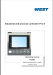
APP 541
This manual is applicable to the following APP 541 versions:
Hardware:
Operator panel:
I/O-module:
Com-module:
AFH1801 Rev 1.02
AHH1801 Rev 1.02
TMX1801 Rev 1.00
System Software: 2.2X
Application:
1.1X
© Copyright 2005 ITT Flygt AB. All rights reserved. No part of this manual may be reproduced or copied
without the written permission of ITT Flygt AB.
ITT Flygt AB
P.O.Box 2058
SE-291 02 Kristianstad
Sweden
Tel+46 44 20 59 00
June 2005
This document may be changed without any prior notice.
Contents
Contents
1.
2.
3.
Read this first .......................... 5
1.1. Product documentation ........................
1.2. Safety rules for the owner/operator .....
1.3. Guarantee .............................................
1.4. This manual ...........................................
1.4.1. Symbols used .......................................
1.4.2. Abbreviations ......................................
5
5
5
5
5
5
2.1. Operator panel ......................................
2.2. Push buttons .........................................
2.3. Menu groups and menus ......................
2.3.1. Menu level indicator ............................
2.4. Viewing a menu ....................................
2.5. Changing a parameter ..........................
2.6. Show hidden service menus .................
2.7. Miscellaneous buttons ..........................
2.8. Language ..............................................
2.9. Explanation of LEDs ..............................
6
6
6
7
7
7
7
8
8
9
4.
Introduction ............................ 6
Configuration........................ 10
3.1. Configuration of the I/O-module .......
3.1.1. Connection ........................................
3.1.2. Mac address .......................................
3.1.3. IP address ...........................................
3.1.4. IP time-out .......................................
3.2. Level control .......................................
3.3. Level sensor control ............................
3.3.1. Setting the level sensor ......................
3.3.2. Calibrating the level sensor ................
3.3.3. Start and stop levels ...........................
3.3.4. Stop delay ..........................................
3.4. Current measurement and alarms ......
3.4.1. Current measurement ........................
3.4.2. High current and low current .............
3.5. General purpose inputs ......................
3.5.1. General inputs functions 1 - 8 ............
3.5.2. P1 Manual - P4 Manual ......................
3.5.3. Power failure ......................................
3.5.4. External alarm ....................................
3.5.5. Blocking .............................................
3.5.6. Personnel alarm .................................
3.5.7. Rain meter .........................................
3.5.8. Overflow sensor .................................
3.5.9. Low level float ....................................
3.5.10. High level float .................................
3.5.11. High temp P1 - P4 ............................
3.5.12. P1 - P4 Spare alarm ..........................
3.6. Miscellaneous ......................................
3.6.1. Power failure ......................................
3.6.2. Emergency operation output .............
3.6.3. Selectable function for digital
output 4 .............................................
10
10
10
10
10
10
10
10
11
11
11
12
12
12
12
12
13
13
13
13
13
14
14
14
14
14
14
15
15
15
5.
6.
15
3
Pump control functions........ 17
4.1. Pump control ...................................... 17
4.2. Manual/Auto control ........................... 17
4.3. Blocking ............................................... 17
4.4. EX mode .............................................. 17
4.5. Power on delay ................................... 18
4.6. Start delay ........................................... 18
4.7. Minimum pause time .......................... 18
4.8. Number of pumps ............................... 18
4.9. Max. number running pumps ............. 18
4.10. Pump alternation .............................. 18
4.10.1. The order of alternating at pumps during
pump faults ...................................... 19
4.10.2. Pumps which are not part of
alternation ........................................ 19
4.11. Maintenance run ............................... 19
4.12. High level float - backup control ...... 19
4.13. Pump faults ....................................... 19
4.14. High temperature .............................. 19
4.15. Motor protection tripped ................. 19
4.16. Max. run time .................................... 20
4.17. Pump feedback ................................. 20
Pump operating data ........... 21
5.1. Running hours and numbers of starts
5.1.1. Resetting the operating data ..............
5.2. Current ................................................
5.3. Level ....................................................
21
21
21
21
6.1. General alarm delay ............................
6.2. Common alarm output .......................
6.3. Alarm logging .....................................
6.3.1. Viewing alarms ...................................
6.4. Alarm handling ...................................
6.4.1. Alarm priority .....................................
6.4.2. Times for D-alarms .............................
6.4.3. Customized alarm texts ......................
6.4.4. Alarm code filter .................................
6.4.5. SMS ....................................................
22
22
23
23
23
23
24
24
24
24
Alarms................................... 22
Contents
Contents
7.
8.
9.
Communication .................... 29
7.1. Systems ...............................................
7.1.1. Direct communication with the
central system ....................................
7.1.2. Communication via MTC-COM ...........
7.1.3. Modems .............................................
7.2. Connection ..........................................
7.2.1. Connection to a modem or radio .......
7.2.2. Connection to a PC using fixed line ....
7.3. Configuration ......................................
7.3.1. Fixed line FDX .....................................
7.3.2. Fixed line HDX ....................................
7.3.3. Dialed up modem ...............................
7.3.4. GSM modem ......................................
7.3.5. GSM modem and SMS .......................
29
29
29
29
29
29
29
30
30
30
31
31
31
Fault tracing ......................... 32
8.1. Status of inputs ................................... 32
8.2. Inversion of inputs .............................. 32
8.3. Diagnostic functions ........................... 32
Central system ...................... 33
9.1. Status ..................................................
9.1.1. Remote control ...................................
9.2. Set points ............................................
9.2.1. Set point values ..................................
9.2.2. Alarm code filter .................................
9.2.3. Alarm priority .....................................
9.3. Report .................................................
9.4. Trend ...................................................
33
34
34
34
34
34
35
35
10. Appendix A:
List of menus ........................ 36
11. Appendix B:
Configuring a modem .......... 51
11.1. Example of a TD-33 modem .............. 51
12. Appendix C: Modems and
initialization strings.............. 52
12.1. RTU versus MTC-COM ........................ 52
12.2. RTU versus AquaView ........................ 52
12.3. Initialization strings .......................... 53
4
Read this first
1. Read this first
1.4.1. Symbols used
Before starting using the APP 541 read this chapter
carefully. It contains general information on
documentation, safety and guarantee.
S pec ial information about a func tion.
1.1. Product documentation
Documentation delivered with the APP 541. Check that
this manual version is applicable to the delivered
APP 541 version (see cover inlet).
Information c onc erning the C entral s ys tem.
1.2. Safety rules for the owner/
operator
Information about alarms .
• All government regulations, local health and safety
directives must be observed.
• All danger due to electricity must be avoided.
1.3. Guarantee
1.4.2. Abbreviations
•
CS = Central system
Modifications or changes to the unit/installation
should be done only after consulting ITT Flygt.
RTU = Remote Terminal Unit
• Genuine spare parts and accessories authorized by
the manufacturer are essential for compliance with
the terms of the guarantee. The use of other parts
may invalidate the guarantee.
SCADA = Supervision Control And Data Acqvicition
1.4. This manual
In order to avoid repetition of information, this manual
describes how one pump P1, should be read or entered.
If a second pump or more pumps, are included in the
installation, the corresponding steps must be repeated
on those too.
5
Introduction
2. Introduction
2.2. Push buttons
The APP 541 is a pump controller that consists of two
parts, i.e. a DIN rail-mounted I/O module and a
operator panel.
The push buttons on the panel are used to select
different menus and to edit parameter values.
The APP 541 can use a modem, GSM or radio to
communicate with a SCADA system e.g. the AquaView.
A special communication module is available for this
purpose.
Esc
2.1. Operator panel
Escape
Left arrow
Right arrow
Up arrow
Esc
OK
Reset
Autamatic Pump Pilot
Down arrow
APP 541
OK
See “Explanation of LEDs” on page 9 for an
explanation of the functions.
OK
Remote alarm On/Off
Power LED
Reset
Alarm status LED
Reset
2.3. Menu groups and menus
Relay status LED
• The control parameters and the alarms are shown
on the display on the operator panel.
• Every menu has it own name that describes the
function.
Pump status LED
See “Appendix A: List of menus” on page 36 for a
complete list of menus.
High level LED
Display
6
Introduction
2.3.1. Menu level indicator
To select a higher value, press the Up arrow
button until the required value is displayed.
In addition to being identified by its name, each menu
is also identified by its level and ordinal number
( 2_1_, 2_2_, 2_3_ etc.). This menu level Indicator is
shown for 1 seconds only. If there is an underscore after
the number, there is a submenu, e.g. (14_).
To select a lower value press the Down
arrow button until the required value is
displayed.
2.4. Viewing a menu
For text menus, the next available alternative is
displayed instead of a value.
• To advance one menu at a time:
To save a specified value:
Press repeatedly until the desired menu is
displayed.
OK
• To scroll backwards one menu at a time:
Press repeatedly until the desired menu is
displayed.
Depending on the result, one of the following messages
will be displayed:
• To display the first menu in a submenu group:
OK
Press the OK button.
Value stored
The value has been
saved.
Low value (xx)
The value is below the
permissible range
(shown in the display xx). Enter a higher value.
High value (yy)
The value is above the
permissible range
(shown in the display yy). Enter a lower value.
Press OK.
• To return to the last menu shown in the previous
menu group:
Esc
Press and release.
The message Store failed may be displayed in
exceptional cases if the internal communications circuits
are busy. Repeat the procedure until the value is saved.
2.5. Changing a parameter
• First display the appropriate menu:
OK
To exit the menu without saving the value
Press the OK button. A flashing cursor will
appear.
Esc
If changing of the value is not allowed, the
"Read only" message will be displayed
instead.
Press the Escape button.
2.6. Show hidden service menus
Menus that are used only during installation are not
shown by default.
To show these menus, set the value in the Show more
menus menu to "Yes". If the password function is in use,
enter the password instead in the Show more menus
menu
If the value is numerical, advance to the required
position in the menu window.
Advance with the Right arrow
N.B. The backlight is switched off if the display has
been idle for ten minutes. If open, the Show more
menus menu will close automatically and the Alarm
log menu ("Home") will be displayed.
If the Show more menus is closed, the present menu will
be shown even if the backlight has been turned off.
Move cursor backwards with the Left arrow.
7
Introduction
2.7. Miscellaneous buttons
Shifts to the remote alarm handling state. If
remote alarm handling state is on alarms will
be transmitted to the central system or to the
short message service (SMS).
Reset
Acknowledge a new alarm. The alarm is not
removed from the alarm log.
2.8. Language
The display language can be selected in the language
menu. The following languages are available:
English
French
Norwegian
Finnish
German
Danish
Spanish
Italian
Dutch
Swedish
Hungarian
Polish
A special character will be displayed in the
top left corner of the Language menu.
8
Introduction
2.9. Explanation of LEDs
LED
Power
ON
Flash
Cause
Off
The power supply is off or a fuse is blown.
Green
The power supply is on.
Red
A new alarm has occurred.
Alarm reset
Red
The new alarm has been acknowledged but is still active.
Relay state
Green
The pump relay is activated.
Red
The pump is blocked. Possible causes:
• Auto mode input is passive.
• Pump is blocked by software.
• Remote blocking is active.
• Low level is active.
• EX mode blocking is active.
Red
Pump status Green
Power on delay, the pumps are blocked at 230 V power failure.
The pump is running. The feedback signal from the relay is active.
The pump is faulty. Possible causes:
• High temperature.
Red
• Motor protection has tripped.
Red
High level
Red
The power supply phases are connected in the wrong sequence or one phase
is dead.
The level in the sump is high. Possible causes:
• The high level float is active.
• The analogue sensor value is above the high level alarm limit.
Green
Local/remote
LED
Remote alarm is on and the RTU is ready to dial.
Green An alarm is about to be dialled out.
9
Configuration
3. Configuration
3.1. Configuration of the
I/O-module
An IP address, the Base IP address, is required for the
operator panel. After this address has been entered into
the panel, the program will automatically assign the
address to the I/O-module connected to the operator
panel. All IP addresses must be in a consecutive order.
The ’Yes’ option must first be selected in the
Show more menus menu to obtain access
to the menus.
1. Continue to the B as e IP addres s menu (14_6_1).
2. Enter the IP address in the B as e IP addres s .
3.1.1. Connection
3. Value store.
The I/O-module is connected to the operator panel
through a cross-over FTP (Foil-shielded Twisted Pair) or
an STP (Shielded Twisted Pair) Cat.5 cable.
3.1.4. IP time-out
The communication time-out menu can be adjusted in
the menu IP timeout (14_6_3). The default value is
appropriate for most installations.
3.1.2. Mac address
3.2. Level control
The operator panel communicates with the I/O-module
using IP/Ethernet.
2. Proceed to the I/O-module menu (14_6_) and
press OK.
Pump operation is controlled by level sensor (analogue
signal). The level sensor could be a pneumatic sensor or
an ultrasonic sensor, both of which deliver a 4 - 20 mA
current signal to the RTU.
3. Continue to the I/O-module MAC addres s menu
(14_6_2) and press OK.
Level measurement
1. Go to the I/O setup menu (14_) and press OK.
4. Read the Mac address from the label placed on the
I/O board housing e.g. 255.240.17.
Level sensor
5. Enter the Mac address in the
I/O-module MAC addres s menu and press OK.
6. Value stored.
Settings to be finalized
Sensor range
Start level 1
Stop level 1
High level
3.3. Level sensor control
3.1.3. IP address
3.3.1. Setting the level sensor
The RTU system uses two consecutive IP addresses.
Enter the first IP address in the menu Base IP address.
The second address is automatically assigned to the
I/O-module by the display panel.
1. Display the Sensor range menu (2_12).
2. Press OK.
3. Enter the maximum measuring range for the sensor.
The maximum permissible value is 20.00 metres.
When the operator panel and I(O unit form a local
network, i.e. are connected directly to each other by a
cable, any of the following free addresses can be used.
4. Press OK.
5. Value stored.
• 10.0.0.0 to 10.255.255.255
• 172.16.0.0 to 172.31.255.255
• 192.168.0.0 to 192.168.255.255
If the units are connected to an intranet, two
consecutive addresses must be obtained from your
network administrator.
10
Configuration
3.3.2. Calibrating the level sensor
N.B!:
If necessary, the zero point can be adjusted in the
Calibration menu (2_13).
The Start level 1 and Stop level 1 control the starting
and stopping of the first pump. Setting both values to
0 disables the pump.
To calibrate, proceed as follows:
The Start level 2 and Stop level 2 control the starting
and stopping of the second pump. Setting both values
to 0 disables the pump.
1. Raise the sensor out of the water.
2. Adjust the value in the Sensor calibration menu
until the Level menu shows +00.00 or some other
required value.
The Start level 3 and Stop level 3 control the starting
and stopping of the third pump. Setting both values to
0 disables the pump.
3. Press OK.
The Start level 4 and Stop level 4 control the starting
and stopping of the fourth pump. Setting both values
to 0 disables the pump.
4. Press ESC to return to the Level menu (2_).
Example: The level shown is +00.20 m.
Set Calibration to -00.20 m. Level will now read
+00.00 m.
The application is 'emptying' i.e.
Stop level < Start level < High level
3.3.3. Start and stop levels
If the measured level is below the value in the
Low level menu, the pumps are blocked.
The value 0 disables this function.
10
98
7
6
Which pump is the first and which is the
second, third or fourth depends on the pump
alternation setting.
54
3
2
If the level settings are outside the sensor
range or are mutually incorrect a parameter
error alarm will be generated.
1
If the measured level is above the value in the
High level menu, a high level alarm will be
generated.
1
2
3
4
5
Low level
Stop level 1
Stop level 2
Stop level 3
Stop level 4
6
7
8
9
10
If the measured level is below the value in the
Low level menu, a low level alarm will be
generated.
Start level 1
Start level 2
Start level 3
Start level 4
High level
3.3.4. Stop delay
Stopping of the first pump is delayed by the time
entered in the Stop delay menu.
The start and stop levels determine when a pump starts
and stops.
The value 0 disables the calculation.
1. Display the Level menu (2_).
1. Display the Pump control menu (10_).
2. Press the OK button to display Start level 1 (2_1).
3. Press OK.
2. Press the OK button to display the
Stop delay time menu (10_5).
4. Enter a start level and press the OK button.
3. Press OK.
5. Advance to Stop level 1.
4. Enter a stop delay time and press the OK button.
6. Press OK.
7. Enter a stop level and press the OK button.
8. Repeat step 5 - 7 for Start level 2,
Stop level 2, Start level 3, Stop level 3,
Start level 4 and Stop level 4.
11
Configuration
3.4. Current measurement and
alarms
The alarms are delayed by the general alarm
delay.
One or two separated 0 - 1A AC current transformers is
used for current measurement and for the current
alarms.
3.5. General purpose inputs
N.B. The current is measuring of pair, P1/P3 and P2/P4.
3.4.1. Current measurement
Eight inputs are available for external functions, i.e.
General-Purpose 1 input to General-Purpose 8 input.
Connect the current transformer to the current input
terminals.
The following functions can be selected:
1. Display the P1 Current manu (3_) and press the
OK button.
• None
2. Display the P1/P3 Current range menu(3_4).
• P1 auto, P2 auto, P3 auto and P4 auto
3. Press OK.
• Power failure
4. Enter the rating of the current transformer and
press OK.
• External alarm
If P1 and P3 are of different sizes, specify an cross-over
factor in the menu Current factor P1/P3.
• Personnel alarm
• P1 manual, P2 manual, P3 manual and P4 manual.
• Blocking
• Rain meter
Eg. If P1 draws 5,5 A and P3 draws 8 A, then the factor
will be 5,5 divided 8 = 0,63.
Do the same with P2 and P4.
• Overflow sensor
• Low level float
5. Go to the menu P2 Current (4_).
• High level float
6. Press the OK button.
• P1 High temp, P2 High temp, P3 High temp
and P4 High temp.
7. Display the P2/P4 Current range menu (4_4).
8. Press OK.
• P1 Spare alarm, P2 Spare alarm, P3 Spare alarm
and P4 Spare alarm.
9. Enter the rating of the current transformer and
press OK.
3.5.1. General inputs functions 1 - 8
If P2 and P4 are of a different sizes, specify an cross-over
factor in the menu Current factor P2/P4.
Select the required function in each of the
General-Purpose menus.
3.4.2. High current and low current
1. Display the General inputs menu (14_5_).
The alarm functions activate an alarm when the current
exceeds any of the limitations represented by the
set points.
2. Press the OK button.
1. Display the P1 current menu (3_).
4. Press OK.
2. Press the OK button.
5. Select the required function and press the OK
button.
3. Display the F unc tion gen. input 1 menu (14_5_1).
3. Display the P1 high current menu.
6. For Function gen. input 2 menu to Function gen
input 8 menu, repeat step 3 - 5.
4. Press OK.
5. Enter the value and press the OK button.
6. Repeat step 3-5 for the P1 low current menu.
7. Repeat for the menus P2 current,
P3 current and P4 current.
To disable the functions enter '0' in each menu.
12
Configuration
3.5.2. P1 Manual - P4 Manual
3.5.6. Personnel alarm
Select this function if the RTU is to control the manual
mode of the pumps.
The alarm is designed to give warning of the risk of an
accident that may occur in a risk area, e.g. a pump
station, if a certain defined working time has been
exceeded.
In EX-mode the general inputs 1 to 4 are automatically
assigned as P1 manual, P2 manual, P3 manual and
P4 manual.
The function involves a selector switch, usually a switch
for the lighting in the pump station, being connected to
a General-Purpose input. By turning on the lights when
the work begins the selector switch will be activated.
3.5.3. Power failure
Select this function when the input is connected to an
external device for supervising the power supply e.g.
Phase control.
When the circuit has been closed for the time specified
in the Work time (11_4) menu, the common alarms
output will be activated and the Warning time set in the
Warning time (11_5) menu will begin to run.
When the signal is active the pumps will be blocked to
prevent starting.
If everything is OK the personnel can extend the
Working time by briefly opening the General-Purpose
input (by switching the lighting off and on) or by
pressing the Reset button on the RTU panel, and the
counting of the Working time will then be restarted.
3.5.4. External alarm
An external unit can be connected to a Function gen.
input. When the circuit is closed, an external alarm will
be generated and recorded in the alarm log.
1. Display the Work time menu (11_4).
When a general input is configured as an External alarm
the following will apply:
Function gen. input 1
Function gen. inpu 2
Function gen. inpu 3
Function gen. inpu 4
Function gen. inpu 5
Function gen. inpu 6
Function gen. inpu 7
Function gen. inpu 8
becomes
becomes
becomes
becomes
becomes
becomes
becomes
becomes
2. Press the OK button.
External alarm 1
External alarm 2
External alarm 3
External alarm 4
External alarm 5
External alarm 6
External alarm 7
External alarm 8
3. Set the required maximum working time for the
personnel, before the personnel alarm is activated.
4. Press OK.
5. Display the Warning time menu (11_5).
6. Press OK.
Each extern alarm can have a customized alarm text.
The texts must be entered in the Alarm text input
1-8 menus (11_13). If the first character of the alarm
text is left blank, the standard alarm text will be used
instead. The alarm text can contain extended ASCII
characters. e.g. öøé
7. Set the warning time for the personnel, before
alarm is sending out.
8. Press OK.
At the end of the preset Warning time, the personnel
alarm will be sent out to the central system or the SMS.
(Provided the RTU is equipped with a Communication
module.)
N.B. The local alarm texts can be changed from the
central system.
The corresponding alarm texts can be set in the central
system, using the alarm code filter function.
The personnel alarm always has alarm
priority A and cannot be prevented from
being activated.
3.5.5. Blocking
When the General-Purpose is active, the pumps will be
blocked to prevent them from starting.
The pumps are blocked directly by this signal. The alarm
is delayed by the General alarm delay
1. Display the Alarm setup menu (11_).
2. Press the OK button.
3. Display the General alarm delay menu.
4. Press OK.
5. Set the required value (range 0 to 2 min) and press
the OK button.
13
Configuration
3.5.7. Rain meter
3.5.9. Low level float
The input is connected to a rain meter.
Select this function when the input is connected to a
low level switch.
Enter the scale factor for your particular rain meter. If,
e.g. a rain meter is specified to give 0.2 mm/pulse, enter
0.2 in the Rain scale factor menu (9_3).
The pumps are blocked directly by this signal. The alarm
is delayed by the Low level alarm delay
1. Display the Alarm setup menu (11_).
The daily value can be read in the display.
2. Press the OK button.
When the 5 minute average value exceeds
the value in the Rain alarm 5 minute menu
an alarm will be generated.
3. Display the Low lev. alarm delay menu.
4. Press OK.
When the daily rain value exceeds the value
in the Rain alarm 24 hour menu an alarm
will be generated.
5. Set the required value (range 0 to 2 min) and press
the OK button.
3.5.10. High level float
The rain 5 minute average value is available
as a trend.
The actual daily value can be read in the
central system status.
The rain alarm state is indicated in the central
system status.
Select this function when the input is connected to a
high level switch.
The pumps are blocked directly by this signal. The alarm
is delayed by the General alarm delay.
1. Display the Alarm setup menu (11_).
1. Display the Rain menu (9_).
2. Press the OK button.
2. Press the OK button.
3. Display the General alarm delay menu.
3. Display the Rain alarm 5min menu (9_1).
4. Press OK.
4. Press OK.
5. Set the required value (range 0 to 2 min) and press
the OK button. The input activates the back run
function. See “High level float - backup control” on
page 19
5. Set the required value (range 0 and 99,9/5 minute).
6. Press OK.
7. Display the Rain alarm 24h menu (9_2).
3.5.11. High temp P1 - P4
8. Press OK.
Select this function when the input is connected to a
thermal overload switch.
9. Set the required value (range 0 and 999,9/24h).
10.Press OK.
The pumps are blocked by this signal. The alarm is
delayed by the General alarm delay
11. Display the Rain scale factor menu (9_3). and press
OK.
3.5.12. P1 - P4 Spare alarm
12.Set the scale factor for your particular rain meter .
Select this function when the input is connected to an
external device that supervises the pump.
13.Press OK.
3.5.8. Overflow sensor
The General-Purpose serves as the input for an overflow
sensor. The accumulated overflow time and the number
of overflow occasions are recorded and can be read in
the Overflow count (8_1) and Overflow time (8_2)
menus.
The recorded values in the two menus can be reset.
N.B. The daily number of overflows and the overflow
time values can be read in the central system status.
The number of overflows and the overflow times are
available as reports.
14
Configuration
3.6. Miscellaneous
3.6.3.1. Reset motor protection
3.6.1. Power failure
The following applies only when the function reset
motor protection is chosen.
The power supply is supervised by the MIO501, which
results in 2 signals.
Signal
24 V unit
When a motor protection trips and the automatic reset
function is enabled in the Automatic reset menu, the
RTU will first wait for 3 minutes for the protection to
cool and will then try to reset the motor protection.
230 V unit with
24 V battery.
The supply is dead.
The motor protection can be reset from the operator
panel, by pressing the Reset button or reset from the
central system by sending the Reset remote control
command.
230 V fail A 230V unit can
be supplied
through the 24V
supply. In that
case the 230 V
fail signal must
be inverted in
order to avoid
the 230 V failure
alarm.
24 V fail 24 V supply is
The battery is low.
low or dead.
Reset can only be done when the pumps is standing still.
To activated the Automatic reset of reset motor
protection do as follows:
1. Display the General menu (13_).
2. Press OK.
3. Display the Auto reset menu (13_3) and
select “Yes”.
3.6.2. Emergency operation output
4. Press OK.
When the RTU is in normal operation the emergency
operation output disconnects the emergency operation
circuit. If the RTU fails to operate correctly, the output
will be closed and the emergency circuit will take over
control of the pumps.
3.6.3.2. Cleaning valve
The following applies only when the function cleaning
valve is chosen.
After a number of pump cycles the valve will be open at
chosen for a preset time.
3.6.3. Selectable function for digital
output 4
To activated the sprinkler function.
When 3 or less pumps are used, the digital output 4 can
be configured to be used by one of the following
functions:
1. Display the Pump control (10_) menu and
press OK.
• Cleaning valve
2. Display the Flushing interval menu (10_17) and
enter the number of pump cycles between each
flushing.
• General output
3. Press OK.
The function is chosen in the Output 4 mode menu.
4. Display the Flushing, time menu and enter the time
during which the flushing valve will be open.
The function is disabled by entering 0 in the menu.
• Reset motor protection
1. Display the Outputs menu (14_7)
2. Press OK.
5. Press OK.
3. Display the F unction output 4 menu (14_7_1).
4. Press OK.
5. Select the required function and press the
OK button.
15
Configuration
3.6.3.3. General output
3.6.3.4. Flygt default set points
The following General output menu is only visible when
the function general output is chosen. Choose between
a combination of following functions signals.
This function resets the RTU to a known default status
(14_9).
The initial status is:
• Power failure
• Language: English
• High level
• P1 failure
Measurement range: 1 metre and with appropriate
starting and stopping levels.
• P1 blocked
• Extra functions: Shut off
• P2 failure
1. Display I/O setup menu (14_).
• P2 blocked
2. Press OK.
• P3 failure
3. Proceed to the Flygt default menu (14_9).
• P3 blocked
4. Press OK.
5. Shift to "Yes" and press OK.
1. Display the Output. 4 config menu (14_7_2).
6. Wait until the RTU has restarted.
2. Press OK.
3. Select the required function and press the
OK button.
16
Pump control functions
4. Pump control functions
4.1. Pump control
Function gen. input 1-8 menus. Selection of the four
manual functions is mandatory when the EX-mode is
On, in which case the Function gen. inputs 1 to 4 are
automatically assigned this function.
The pump control is designed for 3 or 4 pumps, but can
also be used in installations with 1 or 2 pumps.
In addition to the parameters described in the previous
chapter, a number of other set points can be specified.
These and the related parameters are described below.
The pumps can be started from the central
system by the remote control commands
Start P1. Start P2, Start P3 and Start P4.
Note that the 'Yes' option must first be
selected in the Show more menus menu to
gain access to these menus.
4.3. Blocking
When a pump is neither in the automatic or in the
manual mode the state of the pump will be blocked.
This state is indicated by the Pump blocked LED on the
operator panel. In this state no attempt will be made to
start the pump.
4.2. Manual/Auto control
Pump operation is in the automatic mode when the
inputs P1 Auto to P2 Auto are active.
The automatic mode also requires the P1 State,
P2 State, P3 State and P4 State menus to be set to
Automatic.
The pumps can be blocked in the program by setting
the P1 to P4 State menus to Blocked.
See “Manual/Auto control
1. Display the Pump control menu (10_).
A low level condition will temporarily block the pumps.
2. Press the OK button to display the P1 State menu.
The pumps can be blocked externally by selecting the
Blocking function in one of the Function gen. input 1-8.
This affects all pumps in the station.
3. Press OK.
4. Select "Auto" and press the OK button.
The pumps can be blocked from the central
system through the remote control
command Stop and block pumps. This
affects all pumps in the station.
5. Display the P2 State menu and press OK.
6. Select "Auto" and press the OK button.
7. Continue with P3 State menu and
P4 State menu.
4.4. EX mode
The RTU can also control the manual mode of a pump.
Select the function P1 Manual, P2 Manual, P3 Manual or
P4 Manual in four of the functions.
The EX function should be enabled when the RTU is
used in an EX classified environment.
1. Display the I/O setup menu (14_), and press OK.
The RTU blocks the pumps from starting when no liquid
is detected in the sump. To enable the function, select
On in the EX mode menu.
2. Advance to the General inputs menu /14_5).
3. Press the OK button.
4. Display Function gen. input 1 menu.
1. Display the General menu (13_) and press the OK
button.
5. Press OK.
2. Display the EX mode menu (13_2) and press OK.
6. Select the required function and press the
OK button.
3. Select "On" and press the OK button.
This also automatically assigns the functions:
7. For Function gen. input 2 menu to
Function gen. input 8, repeat steps 4 - 6.
Function. gen.
Function. gen.
Function. gen.
Function. gen.
17
input
input
input
input
1
2
3
4
P1 manual
P2 manual
P3 manual
P4 manual
Pump control functions
4.5. Power on delay
4.10. Pump alternation
A power on delay of 10 seconds is applied when the
power supply is restored after power failure. During this
time, the pumps are blocked and the pump blocked
LEDs on the panel will show a flashing red light.
Normally the pump 1 starts at start level 1, pump 2
starts at start level 2, the pump 3 starts at start level 3
and the pump 4 starts at start level 4.
To make the pumps start alternating, select the choice
"On" in Pump alternation menu. This will decide the
starting order by the pumps. Alternation will decide
starting order of the number of pump to use in Pump
alternation menu. The RTU will decide the start order of
the alternating pumps. The others will start at they
normal start level.
4.6. Start delay
The function prevents both pumps from starting
simultaneously. The second pump will start 5 seconds
after the first pump has started.
N.B. The time is adjustable for each pump individually,
default value is 5 seconds.
1. Display Pump alternation menu (10_7)
The time adjusting can be done in Time betw. starts P1
menu from (10_9) to (10_12).
2. Press OK.
3. Select the choice "On".
4.7. Minimum pause time
4. Press OK
A minimum delay of 5-second is applied before a pump
can be restarted after a stop.
5. Specify the Alternating pumps menu.
6. Press OK
4.8. Number of pumps
7. Specify the number of pump to use in the
alternation (2 - 4 ).
In the Number of pumps menu (14_1) the number of
pumps connected in the station (normally 4) is
specified.
8. Press OK.
.
If 3 pumps or less are connected, the signals below get
alternative use functions of digital input:
The number of
alternating
pumps.
2
3
4
• Digital input 7 is used for Low level float.
• Digital input 8 is used for High level float
Digital output 4 can be reconfigured as one of the
following function: Reset motor protection, Sprinkler or
General output.
Alternating
pumps
Reserve
pumps
P1 and P2
P1, P2 and P
P1, P2, P3 and P4
P3 and P4
P4
The pumps which start alternating on other start levels.
See“Selectable function for digital output 4” on
page 15.
Example with 3 pumps alternation.
4.9. Max. number running pumps
Alternating
1
The Max. no. run. pumps menu can be used to limit the
maximum number of pumps running at the same time.
2
1. Display the Max. no. run. pumps menu (10_6).
2. Press OK.
3
3. Enter the maximum number of pumps that are
allowed to run at the same time.
4. Press OK.
Permission
P1 starts at Start level 1
P2 starts at Start level 2
P3 starts at Start level 3
P2 starts at Start level 1
P3 starts at Start level 2
P1 starts at Start level 3
P3 starts at Start level 1
P1 starts at Start level 2
P2 starts at Start level 3
The Alternating starts after the pump cycle has finished
and the pumps stand still.
18
Pump control functions
4.10.1. The order of alternating at pumps
during pump faults
1. Display the High lev run time menu (10_15) and
press OK.
2. Set the required value (range 0 to 10 minutes) and
press the OK button
When a pump can‘t start for example due to a fault or
it is shut off, the next alternating pump will start.
Example with 3 pumps alternation:
4.13. Pump faults
Alternating
Pump faults that prevent the pump from running are:
1
2
Permission
P1 starts at Start level 1
P2 faults
P3 starts at Start level 2
No pump starts at Start
level 3
P3 starts at Start level 1
P2 faults
P1 starts at Start level 2
No pump starts at Start
level 3
• High temperature.
• Motor protection tripped.
This is indicated by the Pump fault LED on the display
panel.
Pump faults that temporarily stop the pump are:
• Max run time.
Pump faults that only initiate an alarm are:
• Feedback error.
If a fault occurs during operation, the spare pump will
only start if the start level condition has been fulfilled.
4.14. High temperature
4.10.2. Pumps which are not part of
alternation
The high temperature input is normally closed (NC).
A high temperature state prevents the pump from
running. When the temperature reverts to normal, the
pump will again be allowed to run.
Pumps which are not part of alternation start at their
own start level.
Eg. P4 starts at Start level 4.
4.15. Motor protection tripped
4.11. Maintenance run
The pump tripped input indicates to the RTU that the
motor protection has tripped. The pump is prevented
from starting.
If the pump has not been started by the normal control
system within the number of hours specified in the
Autostart int (interval) menu, it will be started
automatically by the RTU. The pump will be run for the
time specified in the Auto start time menu.
When a motor protection trips and the automatic reset
function is enabled in the Automatic reset menu, the
RTU will first wait for 3 minutes for the protection to
cool and will then try to reset the motor protection.
1. Display the Auto start time menu (10_14).
2. Press OK.
3. Set the required value (range 0 to 2 minutes) and
press the OK button.
Should the next pump cycle result in a new tipped
condition no further attempts will be made and the
pump fault will persist.
This function is disabled by entering 00:00 in the Auto
start time menu.
Tripped motor protection can be reset from the
operator panel, by pressing the Reset button.
4.12. High level float - backup
control
Reset
When the high level switch is activated, a backup
function will start the pumps. The pumps will run for
the time specified in the High lev run time menu. Time
counting starts when the high level signal becomes
passive.
Press the Reset button on the front panel
to manually reset the motor protection.
The motor protection can be reset from the
central system by sending the Reset remote
control command.
N.B This applies only when output 4 is
chosen as motor protection reset.
See “Reset motor protection” on page 15.
19
Pump control functions
4.16. Max. run time
The maximum permissible pump running time can be
limited to a preset value.
1. Display the Pump control menu (10_).
2. Press the OK button
3. Display the Max. run time menu (10_16).
4. Press OK.
5. Set the required value (0 to 50 minutes) and press
the OK button.
The function can be disabled by entering 0 in the menu
i.e. there is no limit for the maximum pump running
time.
After the time has elapsed an alarm will be
generated and the pump will be stopped.
The value set in the Max. run time menu must exceed
a pumping cycle. When estimating the length of a
pumping cycle, also consider any additions made for
the following functions:
• Stopping delay (when analogue control is used).
• Run time (when digital control is used and the Stop
condition is Run on time).
• High level run time (backup control).
4.17. Pump feedback
The pump feedback input indicates to the RTU that the
pump relay is activated. The signal is expected as a
feedback to activating the pump relay.
In addition to the general alarm delay, the alarm is
delayed by a fixed 5 second start-up delay.
A pump response error alarm will be
generated.
20
Pump operating data
5. Pump operating data
5.1. Running hours and numbers
of starts
Pump operating information is displayed in the
Operating data submenu. The following information is
recorded:
• Running hours for P1, P2, P3 and P4.
• Number of starts for P1, P2, P3 and P4.
5.1.1. Resetting the operating data
To reset a stored value:
1. Display the Operating data menu (7_) and
press OK.
2. Display appropriate menu.
3. Press the OK button. The text "Reset value? No" will
be displayed.
4. Shift between "No" and "Yes" using the Up arrow or
Down arrow button.
5. To set the value to zero, press the OK button while
the 'Yes' option is on. The message "Value stored"
will be displayed.
6. To cancel, press the Esc button.
Pressing the OK button while the "No" option is on
will have the same effect.
5.2. Current
The pump current can be read in the P1 current (3_),
P2 current (4_), P3 current (5_) and P4 current (6_)
menus.
5.3. Level
In the analogue control mode, the actual level is shown
in the Level menu (2_).
21
Alarms
6. Alarms
6.1. General alarm delay
1. Display the Common alarm menu (14_4_1) and
press the OK button.
Alarms are delayed by the time set in the
General alarm delay menu (11_1).
2. Switch between Continuous and Intermittent
indication.
3. Make your choice and press the OK button
4. Display the C om. alarm active 1 menu (14_4_2) and
press the OK button.
5. Select the alarms that are to activate the output.
0 = passive and 1 = active
6. Press the OK button.
The signal is active Alarm
for shorter than
delay
the alarm delay
Alarm
generated
7. Display the C om. alarm active 2 menu (14_4_3) and
press the OK button.
8. Select the alarms that are to activate the output.
A separate alarm delay is used for the Power failure
alarm and the Low level alarm.
9. Press the OK button.
10.Display the C om. alarm ac tive 3 menu (14_4_4) and
press the OK button.
A power failure alarm can be delayed for a maximum of
2 minutes, provided that an external battery is
connected and can supply the unit. The delay is set in
the Pow.fail alarm delay menu.
11. Select the alarms that are to activate the output
12.Press the OK button.
1. Display the Alarm setup (11_) menu and press OK.
2. Scroll to the menu for the Pow.fail alarm delay.
To deactivate the common alarm output:
3. Press OK.
4. Enter the time for the delay and press OK.
Reset
5. Repeat steps 2 to 4 for Low level alarm delay.
Press the Reset button.
6.2. Common alarm output
In the event of an alarm, the 'Common alarm' output
will be activated. The output can be connected to
various types of audible or visual devices (lamps, sirens
and the like) to indicate a fault condition in the unit.
The alarm output will be activated again
when a new alarm has occurred
22
Alarms
6.3. Alarm logging
6.4. Alarm handling
Alarms are recorded in the alarm log. The last 100
alarms are saved.
The Alarm handling menu is used to determine
whether the RTU will send alarms to the central system
or the SMS.
6.3.1. Viewing alarms
Local
The number of active alarms is displayed in the
Alarm log menu (1).
Remote
Clear
OK
Press the OK button to open the log.
No alarms are sent.
Alarms are sent.
The alarm buffer is cleared and the
Alarm handling mode then is set to
Remote.
If the sending fails, e.g. if the recipient is busy or does
not reply, the RTU will wait for 1 minute before the next
attempt. Following each successive failure the waiting
time will be increase by 1 minute until 10 attempts have
failed. The RTU will then wait for 3 hours before then
dialing sequence is recommenced.
The first alarm will be displayed.
Alarm text
6.4.1. Alarm priority
The alarm priority of an alarm determines what happens
with the alarm.
Date and time
A=Active,
P=Passive
Alarm priority;
A,B,C,D
A
B
C
Example: High level float alarm
• Browse the log by repeatedly pressing the Down
button.
• To move instead directly to the latest alarm, press
the Up button.
D
1. Display the Alarm log menu.
F
2. Press the OK button to open the log. The first alarm
will be displayed in the menu window.
H
3. Press the Up/down button to scroll to the required
alarm.
4. Press the OK button.
A "Delete alarm?" message will appear and Current
alarm will be displayed.
5. Choose between "Current alarm" and "All alarms" by
pressing the Down button and then press the OK
button.
6. The alarm will be cleared and the text "Log cleared"
message will be displayed.
To exit the log without changing the log:
Press the Esc button.
Active alarms are not removed from the log.
23
The alarm is sent to the central system and then
on to paging.
The alarm is sent to the central system.
The alarm is local in the RTU.
The alarm is sent to the central system and then
on to paging according the D-alarm time frame
of the central system.
If SMS is used the alarm is sent according the
D-alarm time frame in the RTU.
The alarm is not recorded.
The alarm is recorded in a separate event log, if
available. This is not available in the RTU.
Alarms
6.4.2. Times for D-alarms
6.4.4. Alarm code filter
D-alarms are distributed to paging only during the
period between D-alarm start time and D-alarm end
time. If the alarm occurs at any other time, the central
system/RTU will wait until the D-alarm time frame
begins and will then send the alarm.
The code of the external alarms can be changed in the
Alarm code input 1-8 menus. Changing the alarm code
enables a general alarm to become a specific alarm with
a clearly defined alarm text, appropriate to a particular
station.
E.g. Alarms are sent out between 08:00 and 16:30.
The alarm code filters are normally changed
from the central system.
1. Display the D-alarm start time menu (11_8).
2. Press OK.
3. Enter the time when D-alarms should begin to be
sent to the central system or the SMS.
1. Display the Alarm code filters menu (11_14_).
2. Press the OK button to display
Alarm code input 1.
4. Press the OK button when the cursor is in the last
position.
3. Press OK.
5. Display the D-alarm end time menu (11_9).
4. Enter a new code and press the OK button.
6. Press OK.
5. Repeat step 2-4 for every new code for
Alarm code input 2 - 8.
7. Enter the time when D-alarms should cease to be
sent to the central system or the SMS.
6.4.5. SMS
8. Press the OK button when the cursor is in the last
position.
The RTU can send alarms directly to a mobile phone
using SMS. The information given in the SMS is:
To inhibit the D alarm function, enter 0 in both menus.
An D alarm will be treated as an A alarm.
Station No
Date and time
Alarm priority
6.4.3. Customized alarm texts
1 - Baker street 2004-06-17 21:45 High Level AC
The alarm text of external alarms can be changed in the
Alarm text ipnput 1-8 menus. Extended ASCII characters
can be used e.g. öøé.
Station name
Alarm text
A=Active
P=Passive
The texts are used in the alarm log and in SMS. If the
first character of the text is left blank, the standard
alarm text will be used instead.
1. Display the Alarm text menu (11_13_).
2. Press the OK button to display Alarm text input 1.
3. Press OK.
4. Enter the new text with using the arrow up button
or arow down button.
5. Advance the cursor using with the Right arrow
button.
6. Press the OK button.
7. Repeat step 2-4 for every text for
Alarm text input 2 to Alarm text input 8.
24
Alarms
Alarms
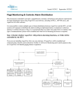
The APP 541 generates alarms in various situations as part of pump monitoring.
Alarm code
1
Default priority Local text
A
High level
Central system text
High level
2
C
Low level
Low level
3
B
Mains error
Mains error
4
A
High level float
High level float
5
A
Pers. alarm
Personnel alarm
11
B
Tripped motor P1 Tripped motor
protector P1.
12
B
Tripped motor P2 Tripped motor
protector P2
13
B
Tripped motor P3 Tripped motor
protector P3
14
B
Tripped motor P4 Tripped motor
protector P3
15
B
High current P1
High current P1
16
C
Low current P1
Low current P1
17
B
High current P2
High current P2
18
C
Low current P2
Low current P2
19
B
High current P3
High current P3
20
B
Low current P3
Low current P3
21
B
High current P4
High current P4
22
B
Low current P4
Low current P4
25
Description
High level in pump sump. Alarm
from the level sensor.
Low level in pump sump. Alarm
from the level sensor.
The main power has been
disrupted or the phase sequence is
incorrect or one phase is missing.
The level in the sump has reached
the high level switch. The pumps
will be started.
Personnel alarm warning time has
run out without having been reset.
Personnel in danger !
The Pump 1 has a tripped motor
protection. The pump is blocked by
this alarm.
The Pump 2 has a tripped motor
protection. The pump is blocked by
this alarm.
The Pump 3 has a tripped motor
protection. The pump is blocked by
this alarm.
The Pump 4 has a tripped motor
protection. The pump is blocked by
this alarm.
High current pump 1. Alarm from
the analogue current
measurement.
Low current pump 1. Alarm from
the analogue current
measurement.
High current pump 2. Alarm from
the analogue current
measurement.
Low current pump2. Alarm from
the analogue current
measurement.
High current pump 3. Alarm from
the analogue current
measurement.
Low current pump3. Alarm from
the analogue current
measurement.
High current pump 4 Alarm from
the analogue current
measurement.
Low current pump3. Alarm from
the analogue current
measurement.
Alarms
Alarm code
27
Default priority Local text
Central system text
H
Setpoint changed Setpoint changed
30
C
No response P1
No response P1
31
C
No response P2
No response P2
32
B
No response P3
No response P3
33
B
No response P4
No response P4
34
A
Overflow
Overflow
35
36
37
38
40
A
A
B
B
C
High temp. P1
High temp. P2
High temp. P3
High temp. P4
Low level float
High temperature P1
High temperature P2
High temperature P3
High temperature P4
Low level float
41
C
Inval.setpoints
Invalid setpoints
81
C
Alarm input 1
Alarm digital input 1
82
C
Alarm input 2
Alarm digital input 2
83
C
Alarm input 3
Alarm digital input 3
84
C
Alarm input 4
Alarm digital input 4
85
C
Alarm input 5
Alarm digital input 5
86
C
Alarm input 6
Alarm digital input 6
87
C
Alarm input 7
Alarm digital input 7
88
B
Alarm input 8
Alarm digital input 8
26
Description
At least one menu has been
changed on the local display. The
alarm reverts when new set points
are sent to the RTU.
There is no feedback signal from
pump 1. The pump has probably
not started despite activation of
the power relay.
There is no feedback signal from
pump 2. The pump has probably
not started despite activation of
the power relay.
There is no feedback signal from
pump 3. The pump has probably
not started despite activation of
the power relay.
There is no feedback signal from
pump 3. The pump has probably
not started despite activation of
the power relay.
Overflowing. The station is now
overflowing.
High temperature in pump 1.
High temperature in pump 2.
High temperature in pump 3.
High temperature in pump 4.
Low level. The pumps will be
stopped.
The level setpoints are incorrect.
The specified setpoints for Start,
Stop or High level is either outside
the calibration range or they are
mutually not corresponding, i.e.
the high level setpoint is lower
than the start level setpoint.
Alarm from digital input 1. The
alarm is user defined.
Alarm from digital input 2. The
alarm is user defined.
Alarm from digital input 3. The
alarm is user defined.
Alarm from digital input 4. The
alarm is user defined.
Alarm from digital input 5. The
alarm is user defined.
Alarm from digital input 6. The
alarm is user defined.
Alarm from digital input 7. The
alarm is user defined.
Alarm from digital input 8. The
alarm is user defined.
Alarms
Alarm code
8214
Default priority Local text
B
Low 24 V Supply
8460
8461
8462
8463
8484
C
C
B
B
B
Central system text
Low 24 V external
supply
P1 Spare alarm
P1 Spare alarm
P2 Spare alarm
P2 Spare alarm
P3 Spare alarm
P3 Spare alarm
P4 Spare alarm
P4 Spare alarm
P1 max. run time P1 max. run time
8485
B
P2 max. run time
8486
B
P3 max. run time
8487
B
P4 max. run time
8505
C
Sensor fault
8538
B
I/O-mod not resp
8539
C
Wrong I/O module
8602
B
High level+pfail
8606
B
P1 switched off
8607
B
P2 switched off
8608
B
P3 switched off
8609
B
P4 switched off
8615
B
Failure 2 pumps
8630
B
Test call !
Description
Low 24 V Supply.
P1 Spare alarm
P2 Spare alarm
P3 Spare alarm
P4 Spare alarm
The pump 1 has exceeded the
maximum allowed run time. The
pump is blocked by this alarm.
See also the Max run time setpoint.
P2 max. run time
The pump 2 has exceeded the
maximum allowed run
time. The pump is blocked by this
alarm.
See also the Max run time setpoint.
P3 max. run time
The pump 3 has exceeded the
maximum allowed run time. The
pump is blocked by this alarm.
See also the Max run time set-point
P4 max. run time
The pump 4 has exceeded the
maximum allowed run time. The
pump is blocked by this alarm.
See also the Max run time set-point
Sensor fault
A fault in the analogue sensor has
been detected. The measured level
is outside the sensor range.
I/O module(s) not
Communication problem with I/Oresponding
moduleule. The I/O-moduleule is
not responding.
Wrong type of I/O
Communication problems with
module
I/O units. Wrong unit type.
High
The level is high and in the same
level+pumpfailure
time there is a failure on at least
one pump
P1 switched off
Pump 1 is switched off. i.e. not in
auto mode.
P2 switched off
Pump 2 is switched off. i.e. not in
auto mode.
P3 switched off
Pump 3 is switched off. i.e. not in
auto mode.
P4 switched off
Pump 4 is switched off. i.e. not in
auto mode.
Failure on two pumps There are failures on 2 or more
pumps.
Test call !
A test alarm is sent in order to
verify that the RTU and its
communication are working
properly. The alarm is sent at a
regular interval, which is
configurable..
27
Alarms
Alarm code
8652
Default priority Local text
C
High rain 5 min
Central system text
High rainfall 5 min
8653
C
High rainfall 24 h
High rain 24 h
28
Description
The RTU has calculated a rainfall
higher than the high alarm limit.
The counter has reached the
maximum value for 24 hours.
Communication
7. Communication
7.1. Systems
7.2. Connection
7.1.1. Direct communication with the
central system
7.2.1. Connection to a modem or radio
Connect a straight serial cable from the modem/radio to
the RS232 connector on the COM1.
In this system the RTU communicates directly with the
central system.
Connect the modem/radio to its own supply.
A modem, a radio or a signal cable is used for the
transmission of information between the units in the
system.
7.2.2. Connection to a PC using fixed line
Connect a straight serial null-modem cable from the PC
to the RS232 connector on the COM1.
Either the factory settings or the first user profile of the
modem (profile 0) can be used. In the first case no
special configuration of the modem is required but in
the second case the user profile has to be configured
prior to use with the RTU.
7.1.2. Communication via MTC-COM
In this system the RTU communicates with the central
system, via the communication unit, MTC-COM.
A modem, a radio or a signal cable is used for the
transmission of information between the units in the
system.
Prior to use with the RTU the first user profile of the
modem (profile 0) has to be configured.
Note! The factory settings of the modem cannot be
used in this case.
7.1.3. Modems
Communication is possible using:
• GSM-modem.
• Hayes-modem.
• Radio in transparent mode.
The modem can either use factory settings or user
profile 0, which must then be pre-configured.
29
Communication
7.3. Configuration
7.3.1. Fixed line FDX
Can be used for:
• Communication directly to a PC.
• Communication using a fix line modem.
• Communication using radio.
Menu
Communication
COM1
Protocol COM1
Speed COM1
Max buffer size
Values
RS232 FDX
Description
Normally FDX can be used if the central system has not specially been set-up
to use HDX.
AquaCom Fix
2400-57600 bps Set this value to the same as the port baudrate in the central system.
80-4000
Normally 2000 is used.
If your radio has a limited buffer or there are disturbances decrease this
value. e.g. 500.
7.3.2. Fixed line HDX
Can be used for:
• Communication directly to a PC.
• Communication using a fix line modem.
• Communication using radio.
Menu
Communication
COM1
Protocol COM1
RTS delay COM1
Speed COM1
Max buffer size
Values
RS232 HDX
Description
Will work with normal settings in the central system.
AquaCom Fix
25-1000 ms
Low delay means faster communication. Use higher value if required by the
radio, i.e. if there are problems with the communication.
2400-57600 bps Set this value to the same as the port baudrate in the central system.
80-4000
Normally 2000 is used.
If your radio has a limited buffer or there are disturbances decrease this
value. e.g. 500.
30
Communication
7.3.3. Dialed up modem
Can be used for:
• Communication using a Hayes compatible telephone modem.
• Communication using a GSM modem.
Note: Please observe the limitation in combinations of modems and their configuration strings.
Menu
Values
Communication COM1 Hayes modem
GSM/Hayes
predef.
Protocol COM1
Speed COM1
Telephone no.
CS/SMS
Description
Select Hayes modem when using TD33 for communication directly to
the central system.
In all other cases configure the modem using a PC and select GSM/
Hayes predefined. See appendix on preconfiguration of modems.
Select this option if an MTC-COM is included in the system.
AquaCom dialled
2400-57600 bps If your modem supports autobauding, set this as high as possible to
get the best communication performances.
Otherwise set this value to the same as the value used in the
preconfiguration of the modem.
Enter the telephone number to the Central system or MTC-COM.
7.3.4. GSM modem
Can be used for:
• Communication using a GSM modem.
Note: Please observe the limitation in combinations of modems and their configuration strings.
Menu
Values
Communication COM1 GSM/Hayes
predef.
Protocol COM1
AquaCom dialled
Speed COM1
2400-57600 bps
Telephone no. CS/SMS
Description
Configure the modem using a PC and select GSM/Hayes predefined.
See appendix on pre-configuration of modems.
If your modem supports autobauding, set this as high as possible to
get the best communication performances.
Otherwise set this value to the same as the value used in the
pre-configuration of the modem.
Enter the telephone number to the SMS recipient, i.e. the personnel.
7.3.5. GSM modem and SMS
Can be used for:
• Communication using a GSM modem or a telephone modem.
Note: Please observe the limitation in combinations of modems and their configuration strings.
Menu
Values
Communication COM1 GSM/Hayes
predef.
Protocol COM1
AquaCom/SMS
Speed COM1
2400-57600 bps
Telephone no. CS/SMS
Station name
Description
Configure the modem using a PC and select GSM/Hayes predefined.
See appendix on pre-configuration of modems.
If your modem supports autobauding, set this as high as possible to
get the best communication performances.
Otherwise set this value to the same as the value used in the
pre-configuration of the modem.
Enter the telephone number to the SMS recipient, i.e. the personnel.
Enter a name that will be sent in the SMS alarm message.
31
Fault tracing
8. Fault tracing
8.1. Status of inputs
The MIO501 has 16 digital inputs plus 2 internal inputs
for supervising the power supply.
The status of the signals can be viewed in the
Status inputs menu (14_2) (0 = non-active, 1 = active).
8.2. Inversion of inputs
The digital input signals can be inverted to change the
operating mode from closing to opening, or vice versa.
0 indicates no inversion. This is the default state.
8.3. Diagnostic functions
The diagnostic menu is used to test the hardware. When
it is activated the normal pump control operation is
deactivated.
Select the desired diagnostic function in the Diagnostic
menu (14_8):
Menu value
Off
Function
None
10
Digital
inputs
11
LED output
Common
alarm
output
Analogue
input
P1 current
input
20
24
25
P2 current
input
Result
The RTU is in normal
operation.
The states of the digital
inputs are displayed
e.g. 1001100100000000
Flashes at 1 second
interval.
Shows the raw input
values (0-16383.
Shows the raw input
values (0-16383). This
starts P1.
Shows the raw input
values (0-16383). This
starts P2.
After 10 minutes the unit will automatically revert to
normal operation.
32
Central system
9. Central system
9.1. Status
The status picture shows the momentary status of the station together with daily operating data along with a list
of active alarms.
P1 running
P1 remote ctrl
P1 relay On
P2 stop
P3 stop
P4 stop
P2 relay Off
P3 relay Off P4 relay Off
RTU info
Active alarms
Power failure
Level
High level
Low level
Sensor range
High level
Tripped
Start levels
Stop levels
Max runtime
High temp.
Response err.
Low level
Rain
Overflow
Rain alarm
Alternation
P1 run time
P1 starts
P1 current
P2 run time
P2 starts
P2 current
P3 run time
P3 starts
P3 current
P4 run time
P4 starts
P4 current
33
Overflow time Remote alarming
Overflow count
Central system
9.1.1. Remote control
As part of the status the RTU can be remotely controlled.
Object
P1
Description
F1 = Start pump 1.
F2 = Stop and block pumps.
F3 = Return control to automatic.
P2
F4 = Reset unit.
F1 = Start pump 2.
F2 = Stop and block pumps.
F3 = Return control to automatic.
P3
F4 = Reset unit.
F1 = Start pump 3.
F2 = Stop and block pumps.
F3 = Return control to automatic.
P4
F4 = Reset unit.
F1 = Start pump 4.
F2 = Stop and block pumps.
F3 = Return control to automatic.
F4 = Reset unit.
The RTU reverts to the automatic mode within 30 seconds after the modem has hung up.
9.2. Set points
9.2.1. Set point values
Set point values can be fetched and sent in random order.
9.2.2. Alarm code filter
Alarm code filter can be fetched and sent in random order.
Fetching alarm code filter requires at least
AquaView 1.23.01.
9.2.3. Alarm priority
Alarm priorities can be fetched and sent in random order.
Fetching alarm priorities requires at least
AquaView 1.23.01.
34
Central system
9.3. Report
The report data consists of daily data divided into 4 segments.
• 00:00 - 06:00
• 00:06 - 09:00
• 09:00 - 16:00
• 16:00 - 24:00
The RTU stores report data for 31 days.
Report
Text1
Run time
Run time
Overflow
Starts
Starts
Rain
Overflow
Text2
P1
P2
Text3
h
h
h:min
P1
P2
mm
Description
Pump 1 running time.
Pump 2 running time.
Overflow time.
Number of pump 1 starts.
Number of pump 2 starts.
Rain.
Number of overflows.
9.4. Trend
The trend data consist of historical data with selectable sample resolution:
• 1-minute average
• 5-minute average
Enter the preferred resolution in the Trend resolution menu (13_4).
The RTU stores trend data for 7 days.
Trend
Text1
Level
Current
P1
Text3
m
A
Current
P2
A
Rain
Text2
mm
Description
Level.
P1 current. (Maximum value
in period).
P2 current. (Maximum value
in period).
Rain 5min average.
Select the same trend resolution in the RTU
settings as in the AquaView.
35
Appendix A: List of menus
10. Appendix A: List of menus
No
1
2_
2_1
2_2
Menu name
Alarm log
Level
m
Start level 1
m
Stop level 1
m
2_3
Start level 2
m
2_4
Stop level 2
m
2_5
Start level 3
m
2_6
Stop level 3
m
2_7
Start level 4
m
2_8
Stop level 4
m
2_9
High Level
m
2_10
Low Level
m
2_11
Random start range
m
Specification
Writable
Read only
Description
Alarm log
Level indication
Writable Interval
-99.99 - 99.99
Central system text
Start level 1
Writable Interval
-99.99 - 99.99
Central system text
Stop level 1
Writable Interval
-99.99 - 99.99
Central system text
Start level 2
Writable Interval
-99.99 - 99.99
Central system text
Stop level 2
Writable Interval
-99.99 - 99.99
Central system text
Start level 3
Writable Interval
-99.99 - 99.99
Central system text
Stop level 3
Writable Interval
-99.99 - 99.99
Central system text
Stop level 4
Writable Interval
-99.99 - 99.99
Central system text
Stop level 4
Writable Interval
-99.99 - 99.99
Central system text
High level
Writable Interval
-99.99 - 99.99
Central system text
Low level
Writable Interval
0.00 - 99.99
Central system text
Random start range
(m)
Start level for first pump
36
(m)
Stop level for first pump
(m)
Start level for second pump
(m)
Stop level for second pump
(m)
Start level for third pump
(m)
Stop level for third pump
(m)
Start level for fourth pump
(m)
Stop level for fourth pump
(m)
High level alarm limit
(m)
Low level alarm limit.
0 - disables the funtion
(m)
Random start range
Appendix A: List of menus
No
2_12
Menu name
Sensor range
m
2_13
Sensor calibration
m
3_
P1 current
A
P1 high current
A
3_1
3_2
3_4
3_5
4_
4_1
P1 low current
A
P1/P3 Current range
A
Current factor P1/P3
P2 current
A
P2 high current
A
4_2
P2 low current
A
4_4
P2/P4 Current range
A
Current factor P2/P4
4_5
5
5_1
5_2
6
P3 current
A
P3 high current
A
P3 low current
A
P4 current
A
Specification
Writable Interval
0.00 - 20.00
Central System Text
Sensor range
(m)
Writable Interval
-20.00 - 20.00
Central System Text
Sensor calibration
Read only
Writable Interval
0.0 - 99.9
Central system text
P1 high current
Writable Interval
0.0 - 99.9
Central system text
P1 low current
Writable Interval
0 - 999
Writable Interval
0 - 99.9
Read only Interval
0.0 - 999.9
Writable Interval
0.0 - 999.9
Central system text
P2 high current
Writable Interval
0.0 - 999.9
Central system text
P2 low current
Writable Interval
0 - 999
0 - 99.9
Read only Interval
0.0 - 99.9
Writable Interval
0.0 - 99.9
Central system text
P3 high current
Writable Interval
0.0 - 99.9
Central system text
P3 low current
Read only Interval
0.0 - 99.9
37
Description
Sensor range
Sensor calibration offset.
(m
Measured current for first pump
High current alarm limit for first
pump
(A)
Low current alarm limit for first
pump
(A)
Current transformer range for
pump 1and 3.
Current factor for P1 versus P3.
Used when P1 and P3 are
difference sizes. Default is 1.0.
Measured current for second
pump.
High current alarm limit for second
pump.
(A)
Low current alarm limit for second
pump.
(A)
Current transformer range for
pump 2 and 4.
Current factor for P2 and P4. Used
when P2 and P4 are difference
sizes. Default is 1.0.
Measured current for pump 3.
High current alarm limit for
pump 3.
(A)
Low current alarm limit for
pump 3.
(A)
Measured current for pump 4.
Appendix A: List of menus
No
6_1
Menu name
P4 high current
A
6_2
P4 low current
A
7_
7_1
7_2
10_
10_1
Operating data
P1 start counter
P1 run hour
h:min
P2 start counter
P2 run hour
h:min
P3 start counter
P3 run hour
h:min
P4 start counter
P4 run hour
h:min
Overflow
Overflow count
Overflow time
h:min
Rain
mm
Rain alarm 5min
mm/5min
Rain alarm 24h
mm/24h
Rain scale
mm/pulse
Pump control
P1 state
10_2
P2 state
10_3
P3 state
10_4
P4 state
10_5
Stop delay time
min:s
7_3
7_4
7_5
7_6
7_7
7_8
8_
8_1
8_2
9_
9_1
9_2
9_3
Specification
Writable Interval
0.0 - 99.9
Central system text
P4 high current
Writable Interval
0.0 - 99.9
Central system text
P4 low current
Read only
Writable
Writable
Description
High current alarm limit for
pump 4.
(A)
Low current alarm limit for pump 4.
(A)
Menu group for operating data.
Number of start for first pump.
Run hour for first pump
Writable
Writable
Number of starts for second pump
Run hour for second pump
Writable
Writable
Number of starts for third pump
Run hour for third pump
Writable
Writable
Number of starts for fourth pump
Run hour for fourth pump
Writable
Writable
Writable
Menu group for overflow.
Number of overflows.
Overflow time.
Read only
Rain daily value.
Writable Interval
0 - 99.9
Writable Interval
0 - 999.9
Writable Interval
0 - 99.9
Read only
Writable Alternative
Auto
Blocked
Writable Alternative
Auto
Blocked
Writable Alternative
Auto
Blocked
Writable Alternative
Auto
Blocked
Writable Interval
00:00 - 10:00
Central system text
Stop delay time
Rain limit for 5 minute period.
38
Rain alarm limit for 24 hours.
Rain meter scale factor.
Pump control group.
Program controlled automatic or
blocked state for first pump.
Program controlled automatic or
blocked state for second pump.
Program controlled automatic or
blocked state for third pump.
Program controlled automatic or
blocked state for fourth pump.
Delays stopping of the pump by the
preset time.
Applicable to stop level 1 only.
(min:s)
Appendix A: List of menus
No
10_6
Menu name
Max. no. run. pumps
10_7
Pump alternation
h
10_8
Alternating pumps
10_9
Time betw. starts P1
min:s
10_10
Time betw. starts P2
min:s
10_11
Time betw. starts P3
min:s
10_12
Time betw. starts P4
min:s
10_13
Auto start interval.
h
10_14
Auto start time
min:s
10_15
High lev. run time
min:s
10_16
Max. run time
min:s
10_17
Flushing interval
h
Specification
Description
Specifies maximum number of
Writable Alternative
pumps running at the same time.
1
1 pump
2
2 pumps
3
3 pumps
4
4 pumps
Central System Text
Max. number of pumps
Writable Interval
The Alternation menu specifies the
On
pump operating sequence.
Off
Central System Text
Pump alternation
Specifies the number of pump to
Writable Interval
use in the alternation.
2-4
Central System Text
Number of alternating pumps
Writable Interval
Delay between two pump starts,
00:00 - 02:00
counted from when P1 started.
Central System Text
Time between starts, P1
(min:s)
Delay between two pump starts,
Writable Interval
counted from when P2 started.
00:00 - 02:00
Central System Text
Time between starts, P2
(min:s)
Writable Interval
Delay between two pump starts,
00:00 - 02:00
counted from when P3 started.
Central System Text
Time between starts, P3
(min:s)
Delay between two pump starts,
Writable Interval
counted from when P4 started.
00:00 - 02:00
Central System Text
Time between starts, P4
(min:s)
Writable Interval
If a pump has not been started
1 - 200
within the set interval, the function
Central System Text
will start the pump for a
Auto start interval
(h) maintenance run, The running time
is set in the Auto start time menu.
The running time when started by
Writable Interval
the auto start function.
00:00 - 02:00
0 - disables the function
Central System Text
Auto start time
(min:s)
Writable Interval
Backup control activated when
00:00 - 10:00
there is a level sensor failure. The
Central System Text
high level switch activates the start
High Level run time
(min:s) of a pump (or two), which will
then run for the period set in this
menu
The maximum time the pumps are
Writable Interval
allowed to run continuously.
00:00 - 50:00
0 - disables the function
Central System Text
Max. run time
(min:s)
Writable Interval
Enter the number of pump cycles
00:00 - 200
between each flushing.
39
Appendix A: List of menus
No
10_18
Menu name
Flushing time
min:s
Specification
Writable Interval
00:00 - 02:00
11_
11_1
Alarm setup
General alarm delay
min:s
11_2
Pow. fail alarm delay
min:s
11_3
Low lev. alarm delay
min:s
11_4
Work time
min
Read only
Writable Interval
00:00 - 02:00
Central System Text
General alarm delay
(min:s)
Writable Interval
00:00 - 02:00
Central System Text
Power failure alarm delay
Writable Interval
00:00 - 02:00
Central System Text
Low level alarm delay
Writable Interval
0 - 240
11-5
Warning time
min
Writable Interval
1 - 15
11_6
Transmit alarm
11_7
Auto remote mode
min:s
Writable Alternative
Local
Remote
Clear
Central System Text
Transmit alarm
Writable Interval
00:00 - 50:00
11_8
D-alarm start time
11_9
D-alarm end time
Writable Interval
00:00 - 23:59
Writable Interval
00:00 - 23:59
40
Description
Enter the time for which the
flushing valve will be open
0 - disables the function.
Menu group for alarm
Delays the recording of an alarm.
Used for all alarms except power
failure alarm and low level.
The delay of a Power failure alarm
before it is recorded
(min:s)
The delay of a Low level alarm
before it is recorded
(min:s)
Work time before an
acknowledgement is required from
the personnel.
Warning time, during which an
acknowledgement from personnel
is requested, before the personnel
alarm is sent.
Alarm transmission.
Local. Alarms are not transmitted.
Remote. Alarms are transmitted to
the Central system/SMS receiver.
Clear. Clears the alarm buffer and
changes to Remote.
The time after which the controller
will revert to remote alarming
mode. 0 - disables the function
The start time for dialling out
alarms with priority D.
The stop time for dialing out alarms
with priority D
Appendix A: List of menus
No
11_10
Menu name
Alarm priority 1
11_11
Alarm priority 2
Specification
Writable
Alternative
Mains error
Low 24V Supply
Sensor Fault
Invalid setpoints
High level float
High level
Low level float
Low level
High level+pfail
Failure 2 pumps
Tripped motor P1
Tripped motor P2
Tripped motor P3
Tripped motor P4
No response P1
No response P2
No response P3
No response P4
Writable Alternative
High current P1
High current P2
High current P3
High current P4
Low current P1
Low current P2
Low current P3
Low current P4
P1 max run time
P2 max run time
P3 max run time
P4 max run time
P1 switched off
P2 switched off
P3 switched off
P4 switched off
High temp. P1
High temp. P2
High temp. P3
High temp. P4
41
Description
Alarm priorities
Alarm priorities. Continuation
Appendix A: List of menus
No
11_12
Menu name
Alarm priority 3
11_13
Alarm texts
11_13_1 Alarm text input 1
11_13_2 Alarm text input 2
11_13_3 Alarm text input 3
11_13_4 Alarm text input 4
11_13_5 Alarm text input 5
11_13_6 Alarm text input 6
11_13_7 Alarm text input 7
11_13_8 Alarm text input 8
11_14
Alarm code filter
11_14_1 Alarm code input 1
11_14_2 Alarm code input 2
11_14_3 Alarm code input 3
Specification
Writable Alternative
P1 Spare alarm
P2 Spare alarm
P3 Spare alarm
P4 Spare alarm
Alarm input 1
Alarm input 2
Alarm input 3
Alarm input 4
Alarm input 5
Alarm input 6
Alarm input 7
Alarm input 8
Pers. Alarm
Overflow
High rainfall 5 min
High rainfall 24 h
Test call!
I/O-mod not resp.
Wrong I/O module
Set-point change
Read only
Writable
Central system text
Alarm text input 1
Writable
Central system text
Alarm text input 2
Writable
Central system text
Alarm text input 3
Writable
Central system text
Alarm text input 4
Writable
Central system text
Alarm text input 5
Writable
Central system textt
Alarm text input 6
Writable
Central system text
Alarm text input 7
Writable
Central system text
Alarm text input 8
Read only
Writable Interval
0 - 9999
Writable Interval
0 - 9999
Writable Interval
0 - 9999
42
Description
Alarm priorities. Continuation
Menu group for alarm texts.
Alarm text to use for general
input 1.
Alarm text to use for general
input 2
Alarm text to use for general
input 3.
Alarm text to use for general
input 4.
Alarm text to use for general
input 5.
Alarm text to use for general
input 6.
Alarm text to use for general
input 7.
Alarm text to use for general
input 8.
Menu group for alarm code filter.
Alternative alarm code to use for
input 1.
Alternative alarm code to use for
input 2.
Alternative alarm code to use for
input 3.
Appendix A: List of menus
No
Menu name
11_14_4 Alarm code input 4
11_14_5 Alarm code input 5
11_14_6 Alarm code input 6
11_14_7 Alarm code input 7
11_14_8 Alarm code input 8
11_15_ Test alarm
11_15_1 Test alarm interval
days
11_15_2 Test alarm time
11_15_3 Test alarm state
12_
Communication
12_1
Station number / id
12_2
Station name
12_3
Telephone CS/SMS
12_4
Communication COM1
12_5
Modem init 1
12_6
Modem init 2
Specification
Writable Interval
0 -9999
Writable Interval
0 - 9999
Writable Interval
0 - 9999
Writable Interval
0 - 9999
Writable Interval
0 - 9999
Read only
Writable Interval
0 - 99
Writable Interval
00:00 To 23:59
Description
Alternative alarm code to use for
input 4.
Alternative alarm code to use for
input 5.
Alternative alarm code to use for
input 6.
Alternative alarm code to use for
input 7.
Alternative alarm code to use for
input 8.
Menu group for test alarm.
Test alarm interval. How often the
test alarm shall be sent.
Test alarm time
The time of the day, at which the
test alarm is sent
Writable
Manual activation of test alarm.
On
Also reflects the current state of the
Off
test alarm.
Read only
Menu group for communication
with the Central system/SMS.
Writable
The unique number of the station
1 - 999
within the system.
Writable
Enter the station name. This name
Central System Text
will be used in SMS calls to a GSM
Station name
telephone.
Writable
Telephone number to central
Central System Text
system or SMS receiver. T=Tone
Telephone number to Central system dial. The telephone number is
/ SMS
required for alarm handling to the
central system or SMS receiver
Type of communication to use for
Writable Alternative
the communication with the
None
Central System.
Hayes modem
GSM/Hayes predefined
RS232 HDX
RS232 FDX
User modem
Writable
Initialization string for the modem.
(part 1)
Applies only when 'User modem' is
selected as communication
Writable
Initialization string for the modem.
(part 2)
Applies only when 'User modem' is
selected as communication
43
Appendix A: List of menus
No
12_7
Menu name
Speed COM1
bps
Specification
Writable Alternative
200
2400
4800
9600
19200
38400
57600
115200
Writable Alternative
AquaCom fixed
AquaCom dialled
AquaCom/SMS
Writable Interval
25 To 1000
12_8
Protocol COM1
12_9
RTS delay COM1
ms
12_10
13_
13_1
13_2
Max. buffer size
bytes
General
Date and time
Ex mode
Writable Interval
80 - 4000
Read only
Writable
Writable Alternative
Off
On
13_3
Auto reset
Writable Alternative
No
Yes
Central System Text
Tripped auto reset
13_4
Trend resolution
Writable Interval
1 - 60
13_5
System version
Read only
13_6
APP 541 version
Read only
44
Description
Speed to use for the
communication with the Central
System.
Choice of transmission protocol to
use for the communication with
the Central System.
Delay for the RTS signal (request to
send) in the communication with
the Central System. Only in choice
of RS 232 HDX.
Limits the data size when collecting
trend.
Menu group for general set-points.
Settings of date and time.
When EX-mode is on, the pumps
are not allowed to start unless
water can be detected in the sump.
The function is used primarily in
explosive environment.
Automatic reset of the motor
protection in the case of an
overcurrent failure.
No. Inactivated function. The RTU
blocks the pump.
Yes. Activated function. The RTU
will make a second attempt to start
the pump.
This function is only available when
'digital output 4' is configured as
'motor protection reset
Trend resolution
The granuality with which the trend
data is stored and transmitted to
the Central System.
1 minute or 5 minute periods
The RTU system version. Please have
this number ready when calling
Flygt support.
The RTU program version. Please
have this number ready when
calling Flygt support.
Appendix A: List of menus
No
13_7
Menu name
Program mode
Specification
Writable Alternative
Run
Remote COM1
13_8
New password
Writable
14_
14_1
I/O setup
Number of pumps
14_2
Status input
14_3
Invert inputs
Writable
Writable Alternative
1-4
Read only Alternative
1 = 24V fail
2 = 230V fail
3 = P1 trip
4 = P1 resp
5 = P2 trip
6 = P2 resp
7 = P3 trip
8 = P3 resp
9 = P4 trip
10 = P4 resp
11 = General input 1
12 = General input 2
13 = General input 3
14 = General input 4
15 = General input 5
16 = General input 6
17 = General input 7
18 = General input 8
Writable Alternative
1 = 24V fail
2 = 230V fail
3 = P1 trip
4 = P1 resp
5 = P2 trip
6 = P2 resp
7 = P3 trip
8 = P3 resp
9 = P4 trip
10 = P4 resp
11 = General input 1
12 = General input 2
13 = General input 3
14 = General input 4
15 = General input 5
16 = General input 6
17 = General input 7
18 = General input 8
45
Description
Run - The controller is in normal
operation controlling the pumps.
Remote - The controller is waiting
for a remote connection to be
established, in order to perform
some management activity. E.g.
loading a new applicatin program.
Activates the service password,
which prevents unauthorized
access to service menues.
The password is disable by the
value 0000
Menu group for I/O setup
Specifies the number of pumps
connected in the station.
Status of the digital inputs
Inverts an input from being NO
(normally open) to NC (normally
closed).
0 =not inverted
1 = inverted
Appendix A: List of menus
No
14_4_
Menu name
Common alarm
Specification
Writable
14_4_1
Common alarm
14_4_2
Com. Alarm activ 1
14_4_3
Com. Alarm activ 2
Writable Alternative
Continuous
Intermittent
Writable Alternative
1 = Mains error
2 = Low 24V Supply
3 = Sensor Fault
4 = Invalid setpoints
5 = High level float
6 = High level
7 = Low level float
8 = Low level
9 = High level+pfail
10 = Failure 2 pumps
11 = Tripped motor P1
12 = Tripped motor P2
13 = Tripped motor P3
14 = Tripped motor P4
15 = No response P1
16 = No response P2
17 = No response P3
18 = No response P4
Writable Alternative
1 = High current P1
2 = High current P2
3 = High current P3
4 = High current P4
5 = Low current P1
6 = Low current P2
7 = Low current P3
8 = Low current P4
9 = P1 max run time
10 = P2 max run time
11 = P3 max run time
12 = P4 max run time
13 = P1 switched off
14 = P2 switched off
15 = P3 switched off
16 = P4 switched off
17 = High temp. P1
18 = High temp. P2
19 = High temp. P3
20 = High temp. P4
46
Description
Menu group for common alarm
output.
Type of common alarm output.
Continuous or pulsating.
Selects which alarms that activate
the common alarm output. ( part 1
Selects which alarms that activate
the common alarm output. ( part 2
Appendix A: List of menus
No
14_4_4
Menu name
Com. Alarm activ 3
14_5_
14_5_1
General inputs...
Function gen.input 1
14_5_2
Function gen.input 2
Specification
Writable Alternative
1 = P1 Spare alarm
2 = P2 Spare alarm
3 = P3 Spare alarm
4 = P4 Spare alarm
5 = Alarm input 1
6 = Alarm input 2
7 = Alarm input 3
8 = Alarm input 4
9 = Alarm input 5
10 = Alarm input 6
11 = Alarm input 7
12 = Alarm input 8
13 = Pers. Alarm
14 = Overflow
15 = High rainfall 5 min
16 = High rainfall 24 h
17 = Test call!
18 = I/O-mod not resp.
19 = Wrong I/O module
Writable
Writable Alternative
None
P1 hand
Power failure
External alarm
Blocking
Personnel
Rain meter
Overflow
Low level float
High level float
High temp P1
P1 Spare alarm
Central System Text
Function general input 1
Writable Alternative
None
P2 hand
Power failure
External alarm
Blocking
Personnel
Rain meter
Overflow
Low level float
High level float
High temp P2
P2 Spare alarm
Central System Text
Function general input 2
47
Description
Selects which alarms that activate
the common alarm output. ( part 3)
Meny group for general inputs
Select function for general input 1.
Select function for general input 2.
Appendix A: List of menus
No
14_5_3
Menu name
Function gen.input 3
14_5_4
Function gen.input 4
14_5_5
Function gen.input 5
Specification
Writable Alternative
None
P3 hand
Power failure
External alarm
Blocking
Personnel
Rain meter
Overflow
Low level float
High level float
High temp P3
P3 Spare alarm
Central System Text
Function general input 3
Writable Alternative
None
P4 hand
Power failure
External alarm
Blocking
Personnel
Rain meter
Overflow
Low level float
High level float
High temp P4
P4 Spare alarm
Central System Text
Function general input 4
Writable Alternative
None
P5 auto
Power failure
External alarm
Blocking
Personnel
Rain meter
Overflow
Low level float
High level float
High temp P5
P5 Spare alarm
Central System Text
Function general input 5
48
Description
Select function for general input 3.
Select function for general input 4.
Select function for general input 5.
Appendix A: List of menus
No
14_5_6
Menu name
Function gen.input 6
14_5_7
Function gen.input 7
14_5_8
Function gen.input 8
14_6
14_6_1
I/O module
Base IP address
Specification
Writable Alternative
None
P6 auto
Power failure
External alarm
Blocking
Personnel
Rain meter
Overflow
Low level float
High level float
High temp P6
P6 Spare alarm
Central System Text
Function general input 6
Writable Alternative
None
P7 auto
Power failure
External alarm
Blocking
Personnel
Rain meter
Overflow
Low level float
High level float
High temp P7
P7 Spare alarm
Central System Text
Function general input 7
Writable Alternative
None
P8 auto
Power failure
External alarm
Blocking
Personnel
Rain meter
Overflow
Low level float
High level float
High temp P8
P8 Spare alarm
Central System Text
Function general input 8
Read only
Writable
14_6_2
I/O-mod MAC address
Writable
49
Description
Select function for general input 6.
Select function for general input 7.
Select function for general input 8.
Menu group for I/O-module.
Base IP address for the controller
and the I/O board.
2 consecutive addresses are
required. The second address is
automatically assigned within the
system and does not have to be
entered.
The MAC address of the I/O board.
Appendix A: List of menus
No
14_6_3
Menu name
IP timeout
Specification
Writable
14_6_4
14_6_5
I/O-Module type
I/O-Module version
Read only
Read only
14_7_
14_7_1
Outputs...
Function output 4
14_7_2
Output 4 config.
14_8
Diagnos. program
14_9
Flygt default
15
Show more menus
16
Show more menus
password
Read only
Writable Alternative
Motorprotect. reset
Cleaning valve
General output
Writable Alternative
Power failure
High level
P1 failure
P1 blocked
P2 failure
P2 blocked
P3 failure
P3 blocked
Writable Alternative
Off
1-39
Writable Alternative
No
Yes
Writable Alternative
No
Yes
Writable
17
Language
Writable Alternative
English
Deutsch
Nederlands
Français
Dansk
Svenska
Norsk
Español
Magyar
Suomi
Italiano
PycckNN
Polski
50
Description
The timeout for the IP
communication with the I/Omoduleule.
Type of I/O-module.
I/O-module versionon. The value is
fetch from the I/O-moduleule.
Menugroup for Outputs.
Select if the output is to be used as
motor protection reset, Cleaning
valve or General purpose output.
Select which signals that shall
activate the output 4.
Applies only if general purpose
outputs have been selected.
Diagnostic program for test of the
RTU.
Resets all settings to default.
Opens the service menus
Shows hidden menus when
password function is enabled. Enter
password!
Select display language
Appendix B: Configuring a modem
11. Appendix B:
Configuring a modem
11.1. Example of a TD-33 modem
Start Windows Hyperterminal program.
Select and configure the COM port to which the modem
is connected:
• Bits per second: 9600 (or some other speed you
want to use).
• Data bits: 8
• Parity: none
• Stop bits: 1
• Flow control: Hardware
Type "AT&F" and press Enter. The modem will
answer "OK".
Type in the initialization string: E.g. AT&F E0V0 &K3 &D2
\N3 %E0 S36=3 S0=0 and press Enter.
The initialization string must be permanently
stored in the modem: To do this:
• Append "&W" to your initialization string
or
• type "AT&W" after entering the
initialization string.
51
Appendix C: Modems and initialization strings
12. Appendix C: Modems and
initialization strings
12.1. RTU versus MTC-COM
The following modem combinations and configurations can be used. Pre-configured modems must use
initialisation strings as listed below:
Modem in RTU MTC-COM
Baudrate
Westermo
TD-33
Siemens
TC35
4800
Modem in MTC-COM
CourierV90
TDK 2814
Pre-config.
Pre-config.
OK
OK
TDK 5660
Pre-config.
OK
TD22
Pre-config.
OK
TD33
Pre-config
OK
4800
OK
OK
OK
OK
NOT POSSIBLE
TO USE
12.2. RTU versus AquaView
The following modem combinations and configurations can be used. Pre-configured modems must use
initialization strings as listed below:
Modem in RTU
Westermo
TD-33
Factory
Settings
AquaView
Baudrate
2400
4800
9600
19200
Siemens
TC35
2400
4800
9600
19200
Modem in AquaView
TD-33
TD-33
Pre- configured
Factory settings
Not tested since
OK
factory settings is ok
Not tested since
OK
factory settings is ok
Not tested since
OK
factory settings is ok
Not tested since
OK
factory settings is ok
OK
NOT RECOMMENDED
OK
OK
OK
OK
OK
OK
52
CourierV. Everything
Factory settings
OK
OK
OK
OK
NOT RECOMMENDED
OK
OK
OK
Appendix C: Modems and initialization strings
12.3. Initialization strings
Modem
TD-33
Westermo
With errorcontrol
TD-33
Westermo
Without errorcontrol
GD-01
Westermo
Autobauding
TC-35
Siemens
Autobauding
Courier V. Everything
Dipsw
1,2,3,4,5,8=on
6,7,9,10=off
in RTU
AT&F E0V0 &K3 &D2
\N3 %E0 S36=3 S0=0
AT&F E0V0 \N0 &D2 &K3 S0=0
S36=3 %E0
in MTC-COM
AT&F E0V0 &K3 &D2 \N3 %E0 S36=3
S0=0
+MS=V32,1,300,4800,300,4800
Preselection 35 in MTC-COM
O6.02.06
AT&F E0V0 \N0 &D2 &K3 S0=0 %E0
S36=3
+MS=V34,1,300,4800,300,4800
AT&F
AT+IPR=9600
AT+CBST=0,0,1
AT&S0
AT&D2
ATE0V1
AT&F
AT+CBST=0,0,1
AT+IPR=9600
ATE0V1
AT&F1 E0V0 B0 F1 Q0 X4 &A3 &B1
&C1 &D2 &H1 &I0 &K1 &L0 &M4
&N0 &R2 &S0 S27=1
With errorcontrol.
AT&F1 E0V0 X4
Courier V. Everything
Dipsw
1,2,3,4,5,8=on
6,7,9,10=off
Preselection 15 in MTC-COM
O6.02.06
Without errorcontrol.
AT &F1 E0 V0 &B1 &N4 &M0 &K0 X4
Courier V. Everything
Dipsw
1,2,3,4,5,8=on
6,7,9,10=off
Only in combination with TC-35
AT&F E0V0 F5 &C1 &D2 \N0 S0=0
TD-22
Westermo
Dipsw3-1=on
Preselection 14 in MTC-COM
O6.02.06
AT&F E0V0 %C0 \N0 W0 S0=0
+MS11,1,300,4800,0,0
TDK 5660
Preselection 13 in MTC-COM
O6.02.06
AT&F E0V0 \N0 %G0 %E0 %C0 -K0
S0=0
TDK DF2814
Preselection 11 in MTC-COM
O6.02.06
53
Manufactured by:
ITT Flygt AB
P.O.Box 2058
SE-291 02 Kristianstad
Sweden
www.flygt.com