1
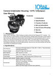
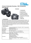
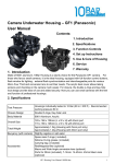
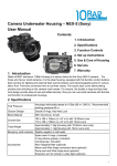
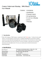
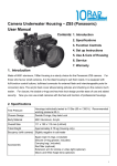
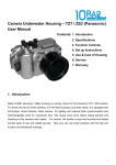
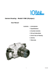
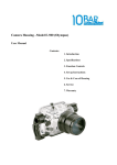
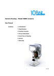
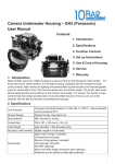
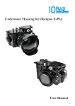
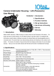
Camera Underwater Housing – E-PL2 (Olympus) User Manual Contents: 1. Introduction 2. Specifications 3. Function Controls 4. Set up Instructions 5. Use & Care of Housing 6. Service 7. Warranty 1. Introduction Made of 6061 aluminum, 10Bar Housing is a sturdy choice for the Olympus E-PL2 camera. For those who favour small cameras, it is the ideal housing, equipped with full-function control buttons, flash window for lighting and external flash synchronization and interchangeable ports for various Micro Four Third and conversion lens to suit their needs. The acrylic back cover allows taking pictures and checking on the camera much easier. For closure, the double o-rings and key-hole lock design provide ease of use and added security. Now you can use small cameras with the feel and function of professional housings. 2. Specifications Closure Design Housings individually tested to 10 Bar (90 m / 300 ft.) Recommended working pressure 60 m Double O-rings, Key-hole Lock Body Material 6061 Aluminum, Acrylic Overall Size 185 x 171 x 146mm (L x W x H) Total Weight Approximately 1.5kg (Housing with ZOOM port only) Test Pressure Buoyancy (with camera) Slightly negative in salt water Spare main O-rings ( included) Silicone O-ring grease ( included) Accessories Carrying bag ( included) Red/Magenta filter (optional) Macro and Wide Angle conversion lens (optional) 1 3. Function Controls 3.1 Buttons & Parts (1) Flash off (2) Bulkhead (3) Mode dial (4) On / Off (5) Shutter (6) Key hole lock (7) Flash on (8) Movie (9) Zoom (10) Info (11) View multiple (12) Controlling exposure (13) Playback (14) AF target (15) OK (16) Delete (17) Menu (18) Sequential shooting / Self-timer (19) Flash (20) Housing lid (21) Zoom Control (22) Zoom Control (23) Focus Control (24) Lens Release 2 3.2 Control Details (1) Flash off – press the lever down to turn off the flash. Make sure that the Flash is turned off before remove the camera from the housing (2) Bulkhead – for connecting sync cord, unscrew the blank plug and install the sync cord. Always keep the blank plug in place if sync cord is not installed (3) Mode dial – switch the mode by press and rotating the button (4) On / Off – align the white dot towards the lid, press and turn the button to turn on and off the camera on (5) Shutter – press to release the shutter (6) Key Hole Lock – press down and turn to lock and unlock the lid (7) Flash on – press the button to open the flash. Make sure that the Flash is turn off with lever (1) before take out the camera from the housing. (8) Movie – press the movie button during any of the following will end shooting without recording a movie (9) Zoom – Press the zoom button to zoom in on picture (10) Info – Press to toggle on/of of the information display (11) Info setting – press the button to view multiple (12) Exposure compensation – Choose positive (“+”) values to make pictures brighter, negative (“–”) values to make picture darker (13) Playback – Press the button to activate (14) AF target – Press the AF targets button to display options (15) OK – press to confirm the setting (16) Delete – rotate to select and press to activate (17) Menu – Press to toggle on/off of the Menu (18) Sequential shooting / Self-timer - press to select (19) Flash – rotate until the white dot align and press (20) Housing Lid – monitor display (21) Zoom Control –press and turn to activate the zoom function with gear ring attached to the lens (22) Zoom Control – press and turn to activate the zoom function with gear ring attached to the lens (23) Focus Control –press and turn to activate the Focus function with gear ring attached to the lens (24) Lens Release – press to release the lens For the full list of camera functions and settings accessed by each control, please consult the Panasonic GF1 camera instruction manual. 4. Set up Instructions 4.1 Special note on responsibility for watertight integrity Each housing is individually inspected and hydrostatically tested in the factory. The design of the main piston O-ring seal is among the most reliable in the industry and the watertight integrity is excellent. This special O-ring design provides a perfect seal even if there is any movement between the body and lid due to change of ambient pressure. However please note that responsibility for ensuring the integrity of the watertight seal lies entirely with the user. 10BAR accepts no liability for damage to, or loss of any equipment used with, or placed inside the housing. Users are highly recommended to carry out in-water test of the housings without 3 installing of the camera for their first dive, after change of new ports or alternation of any new configuration. The test can be carried out by lowering the housing with ballast to the working depth or dive down to the safe diving range. The O-ring seal is the main barrier between the water outside and the air space within the camera. It is an effective barrier only if the seal is properly maintained. The O-ring seal should be inspected before every dive. The following information is provided for guidance in using and maintaining the O-ring seal. 4.2 Maintaining the O-ring Seal If the main body to lid O-rings are not installed, install the O-rings before diving. Their care and maintenance are critical to the watertight integrity of the housing. If the O-rings are contaminated, or not already installed; inspect, grease and install the O-rings according to the following guidelines. 4.3 Inspection, cleaning and re-instillation of the O-rings Tools A soft cotton bud or sponge applicator - make sure these are free of all contamination such as loose fibers, and the tube of silicone grease supplied with the housing. Note other types of silicone grease specifically for use with underwater camera equipment can usually also be used. It is advised to carry out the following procedure on a firm clean level surface, e.g. at a table, to prevent skidding especially when diving from a boat. When to maintain the O-ring seal Remove the O-ring periodically for inspection. It is not necessary to remove, clean and re-install the O-ring after every dive provided the O-rings are not become contaminated. As a rule of thumbs set up the camera and housing before a day’s diving. If the housing is required to be opened between dives for changing memory card or re-charging batteries, make sure the outside of the housing is thoroughly toweled dry before opening up. After removing the lid and servicing the camera, replace the lid straight away, rather than leaving it lying around. Before replacing the lid, check the o-rings and make sure that no contamination such as dust, hair, salt, sand etc. has fallen onto the O-ring or O-ring recess, as a precaution we recommend to inspect the O-ring every time the lid is opened and to carry out the maintenance only if necessary. Procedure Place the lid on a firm non-slip level surface. The O-ring can be extracted using an O-ring extractor tool (make sure the tool has no sharp edges). Alternatively use the flats of the thumbs to gently stretch the O-ring on two faces thus making a small loop protruding a few mm. T he loop can then be grasped between finger and 4 thumb to pull the O-ring over the lip. Clean the O-ring recess (the square groove where the O-ring sits) with a cotton bud or sponge applicator. Inspect the O-ring all the way round its surface for damage such as cuts tears or contamination. This should be done visually and also by feeling the surface texture between finger and thumb. IF THE O-RING IS DAMAGED OR SUSPECTED OF BEING DAMAGED, DISCARD IT and replace with new one immediately. A spare main O-ring is supplied with your housing, or a replacement O-ring can be ordered from 10BAR. If the O-ring is contaminated or suspected of being contaminated, clean it with a cotton cloth that is free of loose fabric and all chemicals or contamination. After cleaning inspect the O-ring again. Once the O-ring has been inspected and verified fit for use, apply a small amount of silicone grease to the O-ring. The silicone grease must be evenly distributed round the O-ring. Replace the O-ring into the groove; run a finger round the O-ring, to make sure it is snugly seated in the groove. 4.4 Key Hole Lock The Key-hole Lock is simple and easy to use and adding security. Turn the levers of the lock perpendicular to the wall of the housing until the lock is released on both sides. Pull out the lid by holding on the grip near the lock. Use the universal key to insert in between the lid and body near the key-hole lock to push off the lid if necessary 5 4.5 Mounting the Gear Ring on the Lens In order to activate the zoom and focus control on the lens, gear rings have to be installed to the lens properly before mounting the lens to the camera. Buttons Zoom Control - 22 Focus Control - 23 For “14-42mm II”Lens the Zoom Gear Ring should be installed first to the position illustrated on the above photo. Then the Focus Gear Ring follows and should be installed to cover the focus ring on the lens as illustrated on the above photo. Buttons Zoom Control - 22 Focus Control - 23 For the“14-42mm ”Lens the Zoom Gear Ring should be installed first to the position illustrated on the above photo. Then the Focus Gear Ring follows and should be installed to cover the focus ring on the lens as illustrated on the above photo. 6 Buttons Zoom Control - 22 Focus Control - 21 For “7-14mm ”Lens the Zoom Gear Ring should be installed first to the position illustrated on the above photo. Then the Focus Gear Ring follows and should be installed to cover the focus ring on the lens as illustrated on the above photo. Buttons Zoom Control - 23 Focus Control - 21 For “14-45mm ”Lens the Zoom Gear Ring should be installed first to the position as illustrated on the above photo. Then the Focus Gear Ring follows and should be installed to cover the focus ring on the lens as illustrated on the above photo. 7 Buttons Zoom Control - 22 Focus Control - 23 For “9-18mm ”Lens the Zoom Gear Ring should be installed first to the position as illustrated on the above photo. Then the Focus Gear Ring follows and should be installed to cover the focus ring on the lens as illustrated on the above photo. 4.6 Mounting the camera in the housing: Slide the hot shoe plug into the hot shoe Install the camera and store the hot shoe plug cable as illustrated below. 8 Replace the lid and make sure the lever is perpendicular to the side wall of the housing. Lock the lid by press down the lever and turn until the lever is parallel to the side wall of the housing. After replacing and locking the lid, make a final visual inspection of the main O-ring for contamination. Note: If the O-ring is in good contact, a thin black line, about 0.5 to 1mm in width should be visible, where the O-ring is in contact with the lid. Follow this line all the way round the edge of the seal, as a final check that the seal is good. The housing is now ready for the dive. 5. Use & Care of Housing 5.1 Pre Dive Function Check. Just before entering the water, make a habit of reviewing that you have carried out the proper steps to close the housing and the bulkhead is connected. Make a visual check of the O-ring seal. It is also useful to switch on the camera, and check that controls e.g. on/off, zoom, shutter functions operate normally. Check housing is closed Check O-ring is in the groove between housing and Acrylic Check battery and memory card status on the LCD display Check the shutter release, control knobs and zoom function. Always avoid submerging the housing in hot water for a prolonged time or a cleansing tank where the water may be heated up by the sun. 5.2 General Operation. The control levers and push buttons consist of internal double O-ring seals on a stainless steel shaft. This arrangement is very reliable, however as a precaution, when operating the controls, avoid excessively rapid movements, as this may distort the O-ring. Also please allow for the fact that the camera takes a while to power on. If the camera dose not appear to respond to a control action, make sure that no other controls are pressing on the camera, i.e. locking out further 9 actions. Wear the wrist strap; it is easy to inadvertently let go of the housing, especially if you are distracted. 5.3 Cleaning & Storage. The body & lid of the housing are made of 6061 Aluminum and Acrylic respectively. 6061 Aluminum is selected for its outstanding strength stiffness, hardness and toughness and epoxy paint is applied to provide extra protection, While Acrylic for its crystal clear transparency and high gloss surface. Both of them have good resistance to weathering, although long-term exposure to sunlight should be avoided. Normal operating temperature range is 3°C to 36°C (Storage temperature: -10°C to 50°C) It is good practice to rinse off your housing with fresh water after every dive. Avoid to exposure to fine sand and sun light. After a series of 10 or more dives, e.g. after a dive holiday, it is recommended to immerse the housing for 1-2 hours in warm water to dissolve any salt deposits that may have built up. No chemical cleaners should be used. Important : For long term storage please remove the main closure o-rings from body. 5.4 Transportation. Please protect the housing during transportation. It is recommended to remove the handle, and shutter extension, and wrap the camera in foam or bubble wrap. 5.5 Accidents The impact resistance of the housing is excellent. However after an accident the alignment of the housing may have been altered. Therefore in the event of your housing suffering an impact force, e.g. being dropped, it is essential that you do not use the housing for diving. Please return the housing immediately for service and put a note inside to indicate the nature of the accident, so that the severity can be assessed. 6. Service To ensure the continued performance of your housing, it should be serviced every year, or after every 200 dives whichever is earlier. Please note the terms for servicing the housing posted at our website. A full service will include: Inspect all components for wears or damage (report if repair necessary), Clean all sealing surfaces, Replace all O-ring seals, Hydrostatic pressure test to 10 Bar. Note: Replacement of damaged components may require additional cost. 10 7. Warranty The warranty is valid within two years from the date of first purchase. The warranty applies only to the housing itself. 10BAR does not accept any liability either implicit or otherwise for any equipment housed inside, or used together with the housing. In the event of the housing flooding within the period of warranty, 10BAR will repair or replace the housing. Please note that disassembly of the housing will invalidate warranty. Please fill in the information below, and return a copy to 10Bar Underwater Housing at the address below, to validate the warranty. (Copy to be retained by user) Housing Type : Date of Purchase: Serial Number : (Labelled inside housing) Dealer : Owner’s Name : e-mail : Owner’s Address: Tel : Fax : Office & Showroom: Unit D, 5/F., Wing Hin Factory Building, 31-33 Ng Fong St., San Po Kong, Hong Kong. Tel: (852) 2573 3228 Fax: (852) 2811 9180 Email: [email protected] Web site: http://www.10bar.com Please keep this document for future reference (Note: due to continuous improvement the latest model of the housing may differ slightly form those described in this document). (Copy to be returned to 10 Bar Underwater Housings) Housing Type : Date of Purchase: Serial Number : (Labelled inside housing) Dealer : Owner’s Name : e-mail : Owner’s Address: Tel : Fax : 11