1
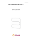
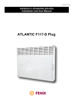
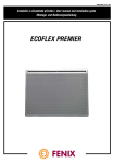
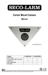
N473/R03 (17.10.13)
Installation and User Manual
ECOFLEX ET
CONVECTION HEATER INSTALLATION
Please read these instructions before commencing
installation of the heater.
Disconnect the heater from the mains before carrying out
any work on it.
Keep these instructions after you have installed the
appliance.
Installation, electrical connection and initial commissioning
may only be performed by a person with the relevant
qualifications (governed by Ordinance 50/78 Coll. in the
Czech Republic).
The panels are intended for wall mounting. Please consult
the manufacturer before attempting any other form of
installation.
Important information regarding installation
The convection heater is a class II device and is protected
against splashing water; IP 24 rating.
In bathrooms the heater must be installed in accordance with
the ČSN 33 200-7-701 standard and can also be installed in
zones 2 and 3 as shown in Fig. 1.
The heater’s controls must not be reachable from the bath or
shower.
The heater must not be placed directly under a mains
socket.
The power supply of the convection heater must ensure
disconnection at all poles; there must be a distance of at
least 3.5mm between disconnected contacts. The precise
settings of the heater are very sensitive to sudden drafts, the
effect of cold tiles, etc. The location of the convection heater
must therefore be selected carefully.
Mounting
The clearance between the bottom edge of the appliance
and the floor must be not less than 15 cm. The clearance at
the sides, e.g. from furniture, and in the upward direction
must also be at least 15 cm. The clearances depicted in Fig.
2 must be complied with in order to ensure the convection
heater operates correctly.
The heater is packed by itself in a cardboard box and is
accompanied by a mounting frame. Attachment of the frame
to the wall is shown in Fig. 3 and 4.
Release the mounting frame from the heater – release the
locking tabs using a screwdriver.
Place the frame onto the floor (which should be in a finished
state, i.e. the distance between floor and appliance will not
decrease after installation of the heater) and mark out the
holes labeled “A” in Fig. 3 and 4 (1). Drill the holes labeled
“A” and insert wall plugs into them.
Move the mounting frame up the wall so that the bottom
openings in the frame are over the wall-plugged holes
labeled “A” - see Fig. 3 and 4 (2). Drill the top holes and
insert wall plugs into them. Screw on the mounting frame
using screws.
Distances A, C and D (see Fig. 5) vary according to the wattage of the convection heaters;
see the table below. C and D describe the position of the heater in relation to the mounting
frame.
Electrical installation
The heater is fitted with a 3-conductor supply cable (A05VVF) for 1/N 230V/50Hz.
Colour marking of conductors:
Phase – brown
Neutral – blue
Pilot wire – black
The power supply cable is connected to a connection box on
the wall; see Fig. 6. If no pilot wire is used, the cable must be
connected to the box at a potential-free terminal. The power
supply cable can only be exchanged by the manufacturer or
approved servicing organization as its exchange requires
special tools.
Pilot wire connection
The convection heater will operate in accordance with signals
which are transmitted by the programming unit.
Heater control (Fig. 8)
Thermostat knob – allows settings ranging from frost
protection up to position 9.
Switch – four functions: Stop (stand-by mode), Program,
Comfort and Eco.
Heating indicator light – indicates that the heating is on.
PROG position – if the convection heater isn´t connected to a controller via a pilot wire, the
required temperature is maintained according to the setting of the thermostat knob. In the
case that the appliance is connected to a programming unit via a pilot wire, the required
temperature is maintained according to the thermostat setting and the transmitted signal.
Comfort position – the required temperature is maintained according to the thermostat knob
setting providing the “stop” or “anti-frost protection” signal has not been transmitted.
Eco position – temperature is maintained at a level 3.5°C lower than the thermostat knob
setting, providing the “stop” or “anti-frost protection” signal has not been transmitted.
Stop position – the heating function’s stand-by mode.
Limiting or blocking thermostat movement (Fig. 9)
Fig.. 8
To limit movement to a maximum required value:
- push out and remove the pegs;
- set the scale of the knob to the maximum required
value;
- screw the peg correctly into the opening marked “M”;
- return the knob to the “ *« position - the knob should
turn freely.
To limit the range between two marks:
- proceed as described in the previous paragraph for
the
setting of a maximum value;
- push out and remove the second peg;
- turn the knob directly to the ‘minimum’ mark;
- screw the peg correctly into the opening which is on
the left of the mark;
- the knob should turn freely between these two pegs.
Fig. 9
removable pegs
To lock indicator rotation:
- turn the knob exactly to the required mark;
- push out and remove one of the pegs;
- screw the peg correctly into the opening marked “F”;
- the knob should be blocked.
Calibration
Place a thermometer in the centre of the room, 1.2 m above the floor (shut the doors
and windows).
Turn the switch to “Comfort”
Set the thermostat to maximum.
As soon as the required ambient temperature is achieved, turn the knob gently
towards its minimum position until the heating indicator switches off.
After setting, the thermostat will maintain the temperature in the room and will switch
the heater on and off alternately.
In order to ensure that all the heaters in the same room function correctly, set the
thermostats to the same temperature.
Removing the convection heater
Note: This may only be carried out by a person with the relevant qualifications.
Before loosening the heater from the mounting frame, set the switch to the off
position.
Loosen the bracket by using a screwdriver on the two locking tabs.
Lift the heater vertically until it is released from the bracket.
Disconnect the power supply cable from the connection box on the wall.
Economical operation
Switch off the convection heaters in a room if you are airing it for a long period. If you
are not using the room, for example a guest room, or the whole house for a longer
period of time (e.g. a holiday), set the knob to the * position. The temperature of the
air in the room will be maintained automatically at approx. 7°C.
Important safety instructions
Do not cover the convection heater under any circumstances. The “DO NOT
COVER” sign warns that any material which covers the heater can cause a fire. No
furniture must be placed or curtains hung in front of the heater; see Fig. 10. Free
circulation of air must be ensured. Remove dust from the inlet and outlet grill
regularly - at least before the beginning of each heating season (Fig. 11).
This appliance is not meant to be used by people (including children) whose physical,
sensory or mental inability or lack of experience or knowledge prevents them from
using the appliance safely if they are not supervised or have not been instructed as
to how to use the appliance by a person who is responsible for their safety.
Children should be supervised in order to ensure that they do not play with the
appliance.
Technical specifications
Warranty conditions
The supplier provides a 24-month warranty from the date of sale. The warranty does
not cover faults caused by transportation, careless manipulation or unqualified
installation. The warranty also does not cover everyday wear and tear on the product.
Any alterations carried out on the product are considered a breach of the warranty
conditions. Complete warranty conditions can be found on the web pages
www.fenixgroup.cz.
Confirmation of sale:
Date of sale:
…………………………………….
Production number: ……………………………….
Seller: ……………………………………………….