1
User Manual
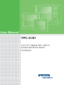
TPC-31/61
3.5"/ 5.7" QVGA TFT LCD TI
Cortex-A8 Touch Panel
Computer
Copyright
The documentation and the software included with this product are copyrighted 2012
by Advantech Co., Ltd. All rights are reserved. Advantech Co., Ltd. reserves the right
to make improvements in the products described in this manual at any time without
notice. No part of this manual may be reproduced, copied, translated or transmitted
in any form or by any means without the prior written permission of Advantech Co.,
Ltd. Information provided in this manual is intended to be accurate and reliable. However, Advantech Co., Ltd. assumes no responsibility for its use, nor for any infringements of the rights of third parties, which may result from its use.
Acknowledgements
IBM, PC/AT and VGA are trademarks of International Business Machines Corporation.
Microsoft Windows and MS-DOS are registered trademarks of Microsoft Corp.
All other product names or trademarks are properties of their respective owners.
This Manual Covers the Following Models:
TPC-31T
TPC-61T
TPC-31/61 User Manual
Part No. 2003003101
Edition 1
Printed in Taiwan
July 2012
ii
Product Warranty (2 years)
Advantech warrants to you, the original purchaser, that each of its products will be
free from defects in materials and workmanship for two years from the date of purchase.
This warranty does not apply to any products which have been repaired or altered by
persons other than repair personnel authorized by Advantech, or which have been
subject to misuse, abuse, accident or improper installation. Advantech assumes no
liability under the terms of this warranty as a consequence of such events.
Because of Advantech’s high quality-control standards and rigorous testing, most of
our customers never need to use our repair service. If an Advantech product is defective, it will be repaired or replaced at no charge during the warranty period. For outof-warranty repairs, you will be billed according to the cost of replacement materials,
service time and freight. Please consult your dealer for more details.
If you think you have a defective product, follow these steps:
1. Collect all the information about the problem encountered. (For example, CPU
speed, Advantech products used, other hardware and software used, etc.) Note
anything abnormal and list any onscreen messages you get when the problem
occurs.
2. Call your dealer and describe the problem. Please have your manual, product,
and any helpful information readily available.
3. If your product is diagnosed as defective, obtain an RMA (return merchandize
authorization) number from your dealer. This allows us to process your return
more quickly.
4. Carefully pack the defective product, a fully-completed Repair and Replacement
Order Card and a photocopy proof of purchase date (such as your sales receipt)
in a shippable container. A product returned without proof of the purchase date
is not eligible for warranty service.
5. Write the RMA number visibly on the outside of the package and ship it prepaid
to your dealer.
Declaration of Conformity
CE
This product has passed the CE test for environmental specifications.
FCC Class A
Note: This equipment has been tested and found to comply with the limits for a Class
A digital device, pursuant to part 15 of the FCC Rules. These limits are designed to
provide reasonable protection against harmful interference when the equipment is
operated in a commercial environment. This equipment generates, uses, and can
radiate radio frequency energy and, if not installed and used in accordance with the
instruction manual, may cause harmful interference to radio communications. Operation of this equipment in a residential area is likely to cause harmful interference in
which case the user will be required to correct the interference at his own expense.
iii
TPC-31/61 User Manual
Technical Support and Assistance
1.
2.
Visit the Advantech web site at www.advantech.com/support where you can find
the latest information about the product.
Contact your distributor, sales representative, or Advantech's customer service
center for technical support if you need additional assistance. Please have the
following information ready before you call:
– Product name and serial number
– Description of your peripheral attachments
– Description of your software (operating system, version, application software,
etc.)
– A complete description of the problem
– The exact wording of any error messages
Warnings, Cautions and Notes
Warning! Warnings indicate conditions, which if not observed, can cause personal
injury!
Caution! Cautions are included to help you avoid damaging hardware or losing
data. e.g.
There is a danger of a new battery exploding if it is incorrectly installed.
Do not attempt to recharge, force open, or heat the battery. Replace the
battery only with the same or equivalent type recommended by the manufacturer. Discard used batteries according to the manufacturer's
instructions.
Note!
Notes provide optional additional information.
TPC-31/61 User Manual
iv
Safety Instructions
1.
2.
3.
4.
5.
6.
7.
8.
9.
10.
11.
12.
13.
14.
15.
16.
Read these safety instructions carefully.
Keep this User Manual for later reference.
Disconnect this equipment from any AC outlet before cleaning. Use a damp
cloth. Do not use liquid or spray detergents for cleaning.
For plug-in equipment, the power outlet socket must be located near the equipment and must be easily accessible.
Keep this equipment away from humidity.
Put this equipment on a reliable surface during installation. Dropping it or letting
it fall may cause damage.
The openings on the enclosure are for air convection. Protect the equipment
from overheating. DO NOT COVER THE OPENINGS.
Make sure the voltage of the power source is correct before connecting the
equipment to the power outlet.
Position the power cord so that people cannot step on it. Do not place anything
over the power cord.
All cautions and warnings on the equipment should be noted.
If the equipment is not used for a long time, disconnect it from the power source
to avoid damage by transient overvoltage.
Never pour any liquid into an opening. This may cause fire or electrical shock.
Never open the equipment. For safety reasons, the equipment should be
opened only by qualified service personnel.
If one of the following situations arises, get the equipment checked by service
personnel:
a.The power cord or plug is damaged.
b.Liquid has penetrated into the equipment.
c.The equipment has been exposed to moisture.
d.The equipment does not work well, or you cannot get it to work according to
the user's manual.
e.The equipment has been dropped and damaged.
f.The equipment has obvious signs of breakage.
DO NOT LEAVE THIS EQUIPMENT IN AN ENVIRONMENT WHERE THE
STORAGE TEMPERATURE MAY GO BELOW -20° C (-4° F) OR ABOVE 70° C
(158° F). THIS COULD DAMAGE THE EQUIPMENT. THE EQUIPMENT
SHOULD BE IN A CONTROLLED ENVIRONMENT.
CAUTION: DANGER OF EXPLOSION IF BATTERY IS INCORRECTLY
REPLACED. REPLACE ONLY WITH THE SAME OR EQUIVALENT TYPE
RECOMMENDED BY THE MANUFACTURER, DISCARD USED BATTERIES
ACCORDING TO THE MANUFACTURER'S INSTRUCTIONS.
v
TPC-31/61 User Manual
Wichtige Sicherheishinweise
1.
2.
3.
4.
5.
6.
7.
8.
9.
10.
11.
12.
13.
14.
Bitte lesen sie Sich diese Hinweise sorgfältig durch.
Heben Sie diese Anleitung für den späteren Gebrauch auf.
Vor jedem Reinigen ist das Gerät vom Stromnetz zu trennen. Verwenden Sie
Keine Flüssig-oder Aerosolreiniger. Am besten dient ein angefeuchtetes Tuch
zur Reinigung.
Die NetzanschluBsteckdose soll nahe dem Gerät angebracht und leicht zugänglich sein.
Das Gerät ist vor Feuchtigkeit zu schützen.
Bei der Aufstellung des Gerätes ist auf sicheren Stand zu achten. Ein Kippen
oder Fallen könnte Verletzungen hervorrufen.
Die Belüftungsöffnungen dienen zur Luftzirkulation die das Gerät vor überhitzung schützt. Sorgen Sie dafür, daB diese Öffnungen nicht abgedeckt werden.
Beachten Sie beim. AnschluB an das Stromnetz die AnschluBwerte.
Verlegen Sie die NetzanschluBleitung so, daB niemand darüber fallen kann. Es
sollte auch nichts auf der Leitung abgestellt werden.
Es sollte auch nichts auf der Leitung abgestellt werden. Alle Hinweise und Warnungen die sich am Ger?ten befinden sind zu beachten.
Wird das Gerät über einen längeren Zeitraum nicht benutzt, sollten Sie es vom
Stromnetz trennen. Somit wird im Falle einer Überspannung eine Beschädigung
vermieden.
Durch die Lüftungsöffnungen dürfen niemals Gegenstände oder Flüssigkeiten in
das Gerät gelangen. Dies könnte einen Brand bzw. elektrischen Schlag auslösen.
Öffnen Sie niemals das Gerät. Das Gerät darf aus Gründen der elektrischen
Sicherheit nur von authorisiertem Servicepersonal geöffnet werden.
Wenn folgende Situationen auftreten ist das Gerät vom Stromnetz zu trennen
und von einer qualifizierten Servicestelle zu überprüfen:
a.Netzkabel oder Netzstecker sind beschädigt.
b.Flüssigkeit ist in das Gerät eingedrungen.
c.Das Gerät war Feuchtigkeit ausgesetzt.
d.Wenn das Gerät nicht der Bedienungsanleitung entsprechend funktioniert
oder Sie mit Hilfe dieser Anleitung keine Verbesserung erzielen.
TPC-31/61 User Manual
vi
Contents
Chapter
1
General Information ............................1
1.1
1.2
Introduction ............................................................................................... 2
Specifications ............................................................................................ 2
1.2.1 System Kernel............................................................................... 2
1.2.2 I/O Ports........................................................................................ 2
1.2.3 Storage ......................................................................................... 2
1.2.4 Safety and Environment................................................................ 3
1.2.5 LCD Specifications........................................................................ 3
1.2.6 Touchscreen Specifications .......................................................... 3
1.2.7 Power............................................................................................ 3
1.2.8 I/O Ports Arrangement .................................................................. 4
Figure 1.1 TPC-31T I/O Ports Arrangement ................................ 4
Figure 1.2 TPC-61T I/O Ports Arrangement ................................ 4
Panel Mounting ......................................................................................... 5
Figure 1.3 Panel Mounting........................................................... 5
Dimensions and Cutout............................................................................. 6
Figure 1.4 TPC-31T Dimensions and Cutout............................... 6
Figure 1.5 TPC-61T Dimensions and Cutout............................... 6
1.3
1.4
Chapter
Chapter
2
System Setup .......................................7
2.1
System Setup............................................................................................ 8
Figure 2.1 Power Connector and Power Lines ............................ 8
Figure 2.2 Pin Assignment on the Power Receptor..................... 8
Figure 2.3 Power Line into the Power Receptor .......................... 9
3
System Tuning ...................................11
3.1
LCD Tuning ............................................................................................. 12
Figure 3.1 Display...................................................................... 12
Figure 3.2 Display Properties .................................................... 12
Touchscreen Calibration ......................................................................... 13
Figure 3.3 Style.......................................................................... 13
Figure 3.4 Stylus Properties ...................................................... 13
Figure 3.5 Touchscreen Calibration........................................... 14
Buzzer Setting......................................................................................... 14
Figure 3.6 Volume & Sounds Settings 1.................................... 14
Figure 3.7 Volume & Sounds Settings 2.................................... 14
3.2
3.3
Chapter
4
Windows CE .......................................17
4.1
Windows CE............................................................................................ 18
Figure 4.1 Windows CE on TPC-31/61...................................... 18
TPC Utilities ............................................................................................ 19
4.2.1 Soft-Keyboard ............................................................................. 19
Figure 4.2 Soft-Keyboard........................................................... 19
4.2.2 TPC Configuration ...................................................................... 19
Figure 4.3 TPC Configurator...................................................... 19
Figure 4.4 General..................................................................... 20
Figure 4.5 Network .................................................................... 20
Figure 4.6 Advanced Network ................................................... 21
Figure 4.7 Watchdog Setting ..................................................... 21
4.2
vii
TPC-31/61 User Manual
4.3
4.4
Figure 4.8 Misc Page................................................................. 22
Figure 4.9 Reboot Machine ....................................................... 22
Figure 4.10Registry Saving Success.......................................... 23
Figure 4.11Registry Editor.......................................................... 23
4.2.3 Advantech Tools ......................................................................... 24
Figure 4.12Advantech Tools....................................................... 24
Figure 4.13NotepadPlus............................................................. 25
Figure 4.14TPC Version Information .......................................... 25
4.2.4 Other Utilities .............................................................................. 26
Networking .............................................................................................. 26
4.3.1 Network via Ethernet .................................................................. 26
Figure 4.15Network and Dial-up Connections............................ 26
Figure 4.16Selected Connection ................................................ 27
Figure 4.17Setting IP Address.................................................... 27
Figure 4.18Settng Name Servers ............................................... 28
Figure 4.19Save Registry ........................................................... 28
4.3.2 Network via Serial Port ............................................................... 29
Figure 4.20PC Connection ......................................................... 29
Figure 4.21PC Connection Properties........................................ 30
Figure 4.22Change Connection.................................................. 30
Figure 4.23Change Connection.................................................. 31
Figure 4.24COM1 Set................................................................. 31
Figure 4.25Microsoft ActiveSync ................................................ 31
Figure 4.26Select Connection Setting ........................................ 32
Figure 4.27Configure Connection Setting .................................. 32
Figure 4.28Get Connected ......................................................... 33
Figure 4.29Run Repllog.exe on the TPC.................................... 33
Figure 4.30Connection on the TPC ............................................ 34
Figure 4.31Connection on the Host PC...................................... 34
Figure 4.32Explore the TPC ....................................................... 35
Application Program Development ......................................................... 35
4.4.1 System Requirements for Developers ........................................ 35
4.4.2 Building Windows CE Runtime ................................................... 36
Figure 4.33Starting a New Project.............................................. 36
Figure 4.34Selecting................................................................... 37
Figure 4.35Compiling Your Program .......................................... 37
Appendix A
Watchdog Timer Programming ....... 39
A.1
A.2
A.3
Device IO Control.................................................................................... 40
How to Use the Control Code ................................................................. 41
A.2.1 IOCTL _WDT_ENABLE:............................................................. 41
A.2.2 IOCTL _WDT_DISABLE:............................................................ 41
A.2.3 IOCTL_WDT_STROBE: ............................................................. 41
A.2.4 IOCTL_WDT_GETTIMEOUT: .................................................... 41
A.2.5 IOCTL_WDT_SETTIMEOUT:..................................................... 42
A.2.6 IOCTL_WDT_REBOOT:............................................................. 42
Examples ................................................................................................ 42
Appendix B
Fuse Specifications .......................... 45
B.1
Fuse Specifications................................................................................. 46
Appendix C
Pin Assignments............................... 47
C.1
C.2
C.3
RS-232 Pin Assignments-TPC-31/TPC-61 (COM1,COM2).................... 48
RS-485 Pin Assignment - TPC-31 .......................................................... 48
RS422(COM3) Pin assignment - TPC-61 ............................................... 49
TPC-31/61 User Manual
viii
Appendix D
Visual Settings ...................................51
D.1
Font Setting............................................................................................. 52
Figure D.1 Font Setting .............................................................. 52
Figure D.2 Small Font Setting .................................................... 52
Figure D.3 Change Font Setting................................................. 53
Figure D.4 Small Font Display.................................................... 53
Screen Rotation ...................................................................................... 54
Figure D.5 Screen Rotation........................................................ 54
Figure D.6 Screen Rotation Options .......................................... 54
Figure D.7 90 Degrees Rotation................................................. 55
Figure D.8 Portrait Rotation........................................................ 55
D.2
Appendix E
TPC-31T /61T Update Guide .............57
E.1
Updating Image & Bootloader ................................................................. 58
Appendix F
Jumper & Dip Switch Setting List ....61
F.1
TPC-31T Component construction.......................................................... 62
F.1.1 EAMB-2201 Top side.................................................................. 62
Jumper Setting DIP Switch ..................................................................... 62
TPC-61T Component construction.......................................................... 63
F.3.1 EAMB-2200 Top side.................................................................. 63
F.3.2 EAMB-2200 Bottom side............................................................. 63
Jumper Setting DIP Switch ..................................................................... 64
F.4.1 SW3 UART Controlled Function ................................................. 64
F.2
F.3
F.4
ix
TPC-31/61 User Manual
TPC-31/61 User Manual
x
Chapter
1
1
General Information
This chapter gives background
information for the TPC-31/61
series.
Sections include:
Introduction
Specifications
LCD Specifications
Touchscreen Specifications
Power
I/O Port Arrangement
Mounting
Dimensions and Cutout
1.1 Introduction
The TPC-31/61 series of touch panel computers consist of state-of-the-art HMI
(Human Machine Interfaces). The 3.5"/5.7” operator interface combined with a RISCbased computing platform offers these key features:
Bright Display:The high-brightness LCD display provides a clear interface.
Fanless: By using a low power processor, the system does not have to rely on
fans, which often are unreliable, and attracts dust.
Powerful Communication Capability:
The TPC-31/61 series provides a powerful I/O interface for easy communication
with other devices. The I/O interface includes serial ports, RS-485 port, Ethernet
and USB. (Serial Port default as RS-232)
Windows CE Support: Advantech offers platform support for Windows CE. The
optional Windows CE operating system specifically for the TPC-31/61 is available for Windows CE application program builders.
1.2 Specifications
1.2.1 System Kernel
CPU: TI Cortex-A8 AM3517 600 MHz
Memory: DDR2 256MB on board
Storage Memory: 512MB on board micro SD card;1Mb FRAM for Data back-up
Ethernet: 10/100Base-T x 1
Watchdog Timer: Programmable as 250 ms, 500 ms, 1 second
SD Slot: Secure Digital Slot
1.2.2 I/O Ports
TPC-31T:
RS-232/RS-485 X1 with auto data flow control, USB 2.0(Host) x 1
TPC-61T:
RS-232 x 2 (COM1,2)RS-422/RS-485 x1 (COM 3) with auto data flow control,
USB2.0 (Host) x 1, USB2.0 (Client) x 1
1.2.3 Storage
TPC-31/61 panel computers provide two methods for storage. One is the on-board
512MB micro SD card and the other one is an external SD card.
TPC-31/61 User Manual
2
Safety
FCC Class A, CE, BSMI, UL certified
The front bezel is compliant with NEMA 4/ IP65
1.2.5 LCD Specifications
TPC-31/61
Display Type
TFT LCD
Size (diagonal)
3.5”/5.7”
Maximum Resolution
320 x 240 (QVGA)
Maximum Colors
64K
Viewing Angle
120/110; 160/140
Luminance (cd / m2)
450/800
Contrast Ratio
300:1 / 800:1
Backlight
LED
Backlight MTBF
30000 / 50000hrs
1.2.6 Touchscreen Specifications
Touch Type
Resistive
Base Glass Construction Glass
Resolution
Continuous
Light Transmission
80% typical
Software Driver
Windows CE (embedded)
Durability
1 million times with a 8 mm diameter silicone rubber finger
Note!
There is no pointer/cursor shown using the touch screen. The cursor
only appears when closing or minimizing the window.
1.2.7 Power
Input Voltage: 18~32 VDC
Maximum Current: 1 A
3
TPC-31/61 User Manual
General Information
Environment
Operating Temperature: 0~50°C (32 ~ 122°F)
Storage Temperature: -20 ~ 60°C (-4 ~ 140°F)
Humidity: 10~95% @ 40°C relative humidity (non-condensing)
Vibration: 1 Grms (Random, Operating)
Chapter 1
1.2.4 Safety and Environment
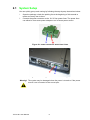
1.2.8 I/O Ports Arrangement
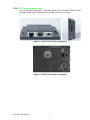
TPC-31T provides 1 serial port, 1 Ethernet LAN port and 1 USB port. While TPC-61T
provides 3 serial ports, 1 Ethernet LAN, 2 USB port(1xHost, 1xClient).
Figure 1.1 TPC-31T I/O Ports Arrangement
Figure 1.2 TPC-61T I/O Ports Arrangement
TPC-31/61 User Manual
4
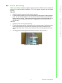
Figure 1.3 Panel Mounting
5
TPC-31/61 User Manual
General Information
There is an adhesive waterproof gasket on the front bezel. Make sure the waterproof
gasket is in position before installing a TPC-31/61 panel computer into the panel
opening.
TPC-31T:
1. Install the panel computer into the panel opening.
2. Find the mount bracket, four short screws and four long screws in the accessory
pack. Fix the mount bracket on the rear cover with four short screws and then
fasten the long screws. These screws will then push the mounting panel and fix
the unit. The mounting panel thickness is suggested to be less than 3.5 mm
(0.137 inch).
TPC-61T:
1. Install the TPC into the panel opening.
2. Find the six clamps and six long screws in the accessory pack. Hook the clamps
to the holes around the four sides of the bezel. Insert the screws into every
clamp and fasten them. These screws will push the mounting panel and fix the
unit.
3. The suggested mounting panel thickness is less than 6 mm (0.236”).
Chapter 1
1.3 Panel Mounting
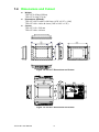
1.4 Dimensions and Cutout
Weight:
TPC-31T: 0.25 kg (0.55 lbs)
TPC-61T: 0.8 kg (1.76 lb)
Dimensions (WxHxD):
TPC-31T: 120.79 x 85.5 x 26.5 mm (4.76" x 3.37" x 1.04")
TPC-61T: 195 x 148 x 44.4 mm (7.68" x 5.83" x 1.75")
Cutout:
TPC-31T: 115 x 79.5 mm
TPC-61T: 189 x 142 mm
Figure 1.4 TPC-31T Dimensions and Cutout
Figure 1.5 TPC-61T Dimensions and Cutout
TPC-31/61 User Manual
6
Chapter
2
2
System Setup
This chapter provides a brief
explanation for operating the TPC31/61.
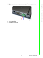
2.1 System Setup
You can quickly get up and running by following the step-by-step instructions below.
1. Open the package. check the packing list at the beginning of this manual to
make sure every item is there.
2. Connect the power connector to the 18~32 VDC power lines. The power lines
can either be from some power adapter or an in-house power source.
Figure 2.1 Power Connector and Power Lines
Figure 2.2 Pin Assignment on the Power Receptor
Warning! The system may be damaged when the power is turned on if the power
source is not connected to the correct pins.
TPC-31/61 User Manual
8
Figure 2.3 Power Line into the Power Receptor
Turn on the System
Calibrate the touchscreen.
9
TPC-31/61 User Manual
System Setup
4.
5.
Plug the power lines into the system power receptor. Thus the system will turn
on.
Chapter 2
3.
TPC-31/61 User Manual
10
Chapter
3
System Tuning
Sections include:
LCD Contrast Tuning
Touchscreen Calibration
Buzzer Setting
3
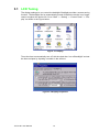
3.1 LCD Tuning
The display settings let you control the backlight. Backlight provides a screen saving
function. The backlight can be automatically turned off when the device is no longer
used to lengthen the device life. Go to “Start” -> “Setting” -> “Control Panel” -> “Display” as shown in the Figure below.
Figure 3.1 Display
To set the time to automatically turn off, tick the check box “turn off backlight” and set
the time to elapse by inputting a number in the edit box.
Figure 3.2 Display Properties
TPC-31/61 User Manual
12
You can calibrate the touchscreen through “Start” -> “Setting” -> “Control Panel” ->
“Stylus” as shown in the Figure below.
System Tuning
Figure 3.3 Style
The window of the stylus properties will display after you click the stylus. There are
two tabs in this screen: Double-Tap and Calibration. Double-Tap is used to record the
time period between the two taps when double-tapping in Windows CE. Calibration is
for users to calibrate the touch screen.
Figure 3.4 Stylus Properties
13
Chapter 3
3.2 Touchscreen Calibration
TPC-31/61 User Manual
Press “Calibration” and then click “Recalibrate” to calibrate the touch screen as
shown below. A cross will appear on the screen in the order: center point, upper-left,
lower-left, lower-right, and upper-right. Use the stylus to tap the center of the cross
until the cross moves to next location.
Figure 3.5 Touchscreen Calibration
3.3 Buzzer Setting
TPC-31/61 panel computers provide a buzzer setting in Windows CE. This function
enables a beep when users use the touch screen. To enable/ disable this functionality, open “Start” -> “Setting” -> “Control Panel” -> “Volume & Sounds” as shown in Figure 3.6.
Figure 3.6 Volume & Sounds Settings 1
As shown in Figure 3.7, you can enable/disable this functionality.
Figure 3.7 Volume & Sounds Settings 2
TPC-31/61 User Manual
14
Chapter 3
System Tuning
15
TPC-31/61 User Manual
TPC-31/61 User Manual
16
Chapter
4
4
Windows CE
Sections include:
TPC Utilities
Networking
Application Program Development
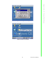
4.1 Windows CE
The TPC-31/61 operator interface terminals are designed for Windows CE. Windows
CE is a compact operating system that occupies less storage space and use less
system resources compared with other operating systems. By its modular nature, it is
possible to choose the functions that are useful for a specific application. This not
only reduced the system resources required, it also reduces start-up time. In the field
of industrial automation or for operator interface terminals, this is an appealing feature because the impact of downtime is minimized. Furthermore, the small storage
space required makes it possible to install the operating system on a reliable solidstate disk.
Note!
The default version of Windows CE in TPC-31/ 61 series is the English
version. Contact your local Advantech representative for local language
support.
Figure 4.1 Windows CE on TPC-31/61
Note!
The TPC-31/61 series also provides Remote Desktop Connection in
Windows CE but the maximum resolution supported is only 320 x 240.
TPC-31/61 User Manual
18
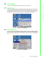
There are several utilities built into Windows CE in the TPC series.
4.2.1 Soft-Keyboard
The TPC-31/61 series also has a small-sized operator interface. Since it is not convenient to attach a keyboard to such a small device, a software keyboard is built into
the standard Windows CE OS. Upon boot-up, a small keyboard icon will appear on
the status bar. Tap this icon with the stylus to activate/hide this Soft-keyboard.
Chapter 4
4.2 TPC Utilities
Windows CE
Figure 4.2 Soft-Keyboard
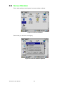
4.2.2 TPC Configuration
The TPC-31/61 series provides an integrated utility to configure the basic settings of
the device. Execute it by clicking the TPC Configurator icon on the desktop. Navigate
the configuration by tapping the four tab pages for: general, network, watchdog and
misc.
Figure 4.3 TPC Configurator
19
TPC-31/61 User Manual
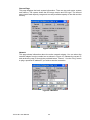
General Page
This page displays the basic system information. There are two main parts: system
and memory. The system shows the OS image version and CPU type. The second
part includes total capacity, usage and currently available capacity of the disk and the
memory.
Figure 4.4 General
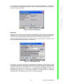
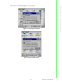
Network
This page shows information about the active network adapter. You can select the
network adapter from the combo box as shown in Figure 4.5. Release the current IP
and retrieve the new IP through the provided button, “Renew”. Use the “Ping” button
to ping a specified IP address if you wish to test the connection.
Figure 4.5 Network
TPC-31/61 User Manual
20
Windows CE
Figure 4.6 Advanced Network
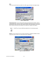
Watchdog
Watchdog is a function to let the device automatically reset if a program does not
respond in time. This prevents system crashes and hangs to stop your critical applications, as the watchdog will automatically restart the machine when required.
Set the response time through the combo box as shown below. The timer is the
period that the watchdog will wait for a response.
Figure 4.7 Watchdog Setting
Only when you select a time span and enable the watchdog, will the response time
be effective. When the watchdog is enabled and the "Test" button is clicked, the NO
resetting signal will be periodically sent to the watchdog hardware onboard. The
watchdog will suppose the machine to be deadlocked and REBOOT it after the
watchdog response time. If the machine reboots as expected after the watchdog
response time, the watchdog is proved to be working properly.
21
Chapter 4
You can get more detailed IP information through “Advanced Network”. The information contains the default gateway, DHCP server, WINS and DNS server address as
shown in Figure 4.6 below.
TPC-31/61 User Manual
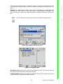
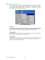
Misc
There are several functions provided in the Misc page as shown in the figure below.
Figure 4.8 Misc Page
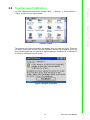
Startup Programs: You can easily set the startup programs without editing. The programs listed in the combo box will be automatically executed after the system has
successfully booted. Click the “Add” button to insert a file to the startup. If you would
like to remove the file from the startup or the combo box, please click “Delete”.
Note!
Do NOT try to insert a NON-executable file into the startup program.
Reboot: You can reboot TPC-31/61 panel computers by clicking the “Reboot” button.
Once this button is clicked, the dialog below will be displayed.
Figure 4.9 Reboot Machine
TPC-31/61 User Manual
22
It is not allowed to backup and restore over different image versions.
Figure 4.10 Registry Saving Success
Figure 4.11 Registry Editor
Web Server Root: Input the root path of the web server here. The root path will only
be effective after the machine has been rebooted.
FTP Server Root: Input the root path of the ftp server here. The root path will only be
effective after the machine has been rebooted.
23
TPC-31/61 User Manual
Windows CE
Note!
Chapter 4
There are two additional ways to reboot the system, clicking a small machine icon on
the status bar and executing a command, reboot.exe, through a command line program.
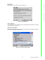
Registry: You can click the “Save” button to save the registry to a solid state disk,
and click the “View” button to view, edit, create, or delete registry information. You
also can backup or restore the registry setting by clicking the backup or restore button.
4.2.3 Advantech Tools
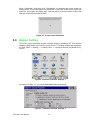
There are several useful tools in the Advantech program. Go to “Start” -> “Programs”
-> “Advantech” to run the tools as shown in Figure 4.12. The tools include “ActiveSync”, “Registry Editor”, “Registry Saver”, “DiagAnywhere”, “NotepadPlus”, “System
Font Setting” and “TPC Version Information”.
Figure 4.12 Advantech Tools
ActiveSync
This program synchronizes data and monitors the connection between TPC-31/61
panel computers and their host computer. By default, it will be executed automatically
when you want to establish a connection to a target device with ActiveSync.
Registry Editor
When Registry Editor is executed as shown in the Figure 4.11, you can use this program to view, edit, enter, delete or save registry data.
Registry Saver
When Registry Saver is executed, the system registry will be saved. Also, you can
execute it in a command-line environment to save the registry like “regsave.exe” or
“regsave.exe -s” for the silence mode.
TPC-31/61 User Manual
24
Chapter 4
NotepadPlus
NotepadPlus is a text editor as shown in Figure 4.17.
Windows CE
Figure 4.13 NotepadPlus
TPC Configurator
TPC Configurator is an integrated utility to configure the basic settings of the panel
computer. Refer to section 4.1.2.
TPC Version Information
TPC Version Information shows the version information of the operation system in
the TPC-31/61 as shown in Figure 4.18.
Figure 4.14 TPC Version Information
25
TPC-31/61 User Manual
4.2.4 Other Utilities
There are other utilities provided in the panel computer. These utilities are commandline executed programs that do not have a graphical user interface. Type the command names shown below in the command-line.
RegSave.exe [-s]:
Saves registry settings. If you use “RegSave.exe -s”, no message box is displayed
whether you are successful or fail.
Reboot.exe:
Saves the registry settings and reboots the panel computer.
Screen.exe [on/off]:
Turns the display on/off. Use “Screen.exe on” to turn on and “Screen.exe off” to turn
off the display.
Iesample.exe [-n] [-f] [ip address/ folder name]:
Open the Internet Explorer. Use "Iesample.exe -n" to close the scroll bar. Use "Iesamples.exe -f" to active the full screen. The three parameters can be blank.
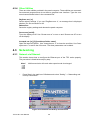
4.3 Networking
4.3.1 Network via Ethernet
This section shows how to configure the Ethernet port of the TPC series properly.
The procedure is listed below step by step.
Note!
1.
LAN transmission will crash when speed mode be changed.
Press Start in the task bar of Windows and select “Setting” -> “Networking and
Dial-up connections”.
Figure 4.15 Network and Dial-up Connections
TPC-31/61 User Manual
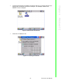
26
A window that shows all available connections will pop up. Double click the icon
that has the connection you want to configure. For example, double click
DM9CE1 icon to configure.
Windows CE
Figure 4.16 Selected Connection
3.
Select the “IP Address” tab.
Figure 4.17 Setting IP Address
27
Chapter 4
2.
TPC-31/61 User Manual
4.
Select the “Name Server” tab.
Figure 4.18 Settng Name Servers
Note!
5.
Do NOT click the Next button at this time.
Press “Start” in of task bar of Windows and select “Run”. Execute “regsave” to
save the registry settings to a storage card.
Figure 4.19 Save Registry
TPC-31/61 User Manual
28
This section introduces how to setup the connection between the TPC series and a
host PC via Microsoft ActiveSync.
Setup the Communication Environment of TPC
Configure COM1 on the TPC. Press “Start” in Windows and select “Setting -> “Control Panel”
Click the icon “PC Connection”
Figure 4.20 PC Connection
29
TPC-31/61 User Manual
Windows CE
ActiveSync Setting Procedure
Insert the TPC CD into the CD-ROM of the host PC
Install the TPC software development kit for eVC++.
Install Microsoft ActiveSync.
Connect the host computer and TPC with a null modem cable (included in the package). Make sure the connection is solid on both RS-232 Serial ports.
Setup the communication environment of the TPC and the host
Chapter 4
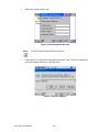
4.3.2 Network via Serial Port
Click 'change...' to select the COM port- serial 1. In this example, we use COM1 of
TPC to connect with COM1 of the host.
Figure 4.21 PC Connection Properties
Check the COM box and select your desired port from the list.
Figure 4.22 Change Connection
TPC-31/61 User Manual
30
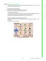
You can find the change is active. The connection is via serial1 - COM1.
Figure 4.24 COM1 Set
Setting the Communication Environment of the Host
Double click the icon ActiveSync on your host computer.
Figure 4.25 Microsoft ActiveSync
31
TPC-31/61 User Manual
Windows CE
Figure 4.23 Change Connection
Chapter 4
Press the 'enter' symbol on the keyboard to confirm the change.
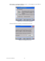
Select “File” -> “Connection Settings”
Figure 4.26 Select Connection Setting
Configure the connection setting.
Figure 4.27 Configure Connection Setting
TPC-31/61 User Manual
32
Chapter 4
A window will pop up after you press “Get Connected”.
Windows CE
Figure 4.28 Get Connected
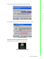
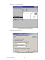
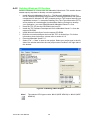
Run “repllog.exe” on the TPC.
Figure 4.29 Run Repllog.exe on the TPC
Press the “Next” button on your host computer.
The message shown below will show on the TPC once the TPC and the host PC are
connected.
33
TPC-31/61 User Manual
Figure 4.30 Connection on the TPC
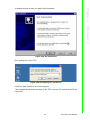
A window will pop up as shown below on the host computer, once the TPC and the
host PC are connected. Select “No” and then press “Next”.
Figure 4.31 Connection on the Host PC
TPC-31/61 User Manual
34
Chapter 4
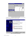
Select “Explore” in the Microsoft ActiveSync window, the window, Mobile Device, will
pop up to display the file resources and information of TPC. For example, you could
click the icon “My documents” to see the content of storage in TPC.
Windows CE
Figure 4.32 Explore the TPC
4.4 Application Program Development
4.4.1 System Requirements for Developers
These are the requirements to run Microsoft eMbedded Visual C++ 4.0.
A desktop computer with a Pentium II-class processor, 450 MHz or faster.
Microsoft Windows 2000 Professional SP4, Microsoft Windows 2000 Server
SP2, or Microsoft Windows XP Professional.
96 MB (128 MB recommended) memory for Windows 2000 Professional or Windows XP Professional. 192 MB (256 MB recommended) memory for Windows
2000 Server.
CD-ROM drive.
VGA or higher-resolution monitor. A Super VGA (800 x 660 or larger) monitor is
recommended.
Mouse or compatible pointing device.
200 MB hard disk space.
Note!
If you choose to install the Common files or Microsoft eMbedded Visual
C++ 4.0 on a partition other than the system partition, the figure representing the amount of space required reflects only the amount of space
for files being installed on that non-system partition. It does not reflect
the total amount of space required to install the entire product. This is
because some files must be installed on the system partition, regardless
of where other files are installed.
35
TPC-31/61 User Manual
4.4.2 Building Windows CE Runtime
Build the Windows CE runtime with the eMbedded Visual tools. This section demonstrates step by step how to develop a custom application.
1. Install Microsoft eMbedded Visual C++: The Microsoft eMbedded Visual C++
tool is a desktop development environment for creating applications and system
components for Windows CE .NET-powered devices. This version features new
capabilities such as C++ exception handling, Run Time Type Information (RTTI),
and a plethora of new debugger functionalities. Before you begin to develop
your application, you must install Microsoft eMbedded Visual C++ first
2. Insert the TPC CD into the CD-ROM in the host PC.
3. Install the TPC Software Development Kit for eMbedded Visual C++ from the
support CD-ROM.
4. Install Microsoft ActiveSync from the support CD-ROM
5. Build the connection between the host and TPC via ActiveSync. For further
information about ActiveSync, please refer to section 4.2.2.
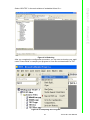
6. Execute eMbedded Visual C++.
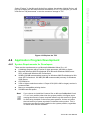
7. Select “File” -> “New” to open a new project. Select your project type in the left
side of the window and enter the new project name/ location in the right side of
the window.
Figure 4.33 Starting a New Project
Note!
The selected CPU type must be Win32 (WCE ARM V4) or Win32 (WCE
ARMV4I).
TPC-31/61 User Manual
36
Chapter 4
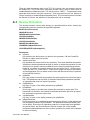
Select “ADVTPC” in the main window of embedded Visual C++.
Windows CE
Figure 4.34 Selecting
After you complete the configuration procedure, you can start to develop your application. Press “Build” to compile your program to a.exe file and download it to TPC.
Figure 4.35 Compiling Your Program
37
TPC-31/61 User Manual
TPC-31/61 User Manual
38
Appendix
A
Watchdog Timer
Programming
A
There is a built-in watchdog timer in the TPC-31/61 series. You can access it through
the WIN32 API. TPC-31/61 panel computers provide a WDT driver to allow users to
enable/disable the Watchdog timer. The driver name is “WDT1:”. Programmers must
open this driver before using the resources. Then programmers can use Device IO
Control functions to enable/disable Watchdog timer. The introduction below includes
the Device IO Control, the definition of the parameter and an example.
A.1 Device IO Control
This function sends a control code directly to a specified device driver, causing the
corresponding device to perform the specified operation.
BOOL DeviceIoControl(
HANDLE hDevice,
DWORD dwIoControlCode,
LPVOID lpInBuffer,
DWORD nInBufferSize,
LPVOID lpOutBuffer,
DWORD nOutBufferSize,
LPDWORD lpBytesReturned,
LPOVERLAPPED lpOverlapped );
Parameters:
hDevice
[in] Handle to the device that is to perform the operation. Call the CreateFile
function to obtain a device handle.
dwIoControlCode
[in] Specifies the control code for the operation. This value identifies the specific
operation to be performed and the type of device on which the operation is to be
performed. No specific values are defined for the dwIoControlCode parameter.
However, the writer of a custom device driver can define IOCTL_XXXX control
codes, per the CTL_CODE macro. These control codes can then be advertised,
and an application can use these control codes with DeviceIoControl to perform
driver-specific functions.
lpInBuffer
[in] Long pointer to a buffer that contains the data required to perform the operation. This parameter can be NULL if the dwIoControlCode parameter specifies
an operation that does not require input data.
nInBufferSize
[in] Size, in bytes, of the buffer pointed to by lpInBuffer.
lpOutBuffer
[out] Long pointer to a buffer that receives the operation’s output data. This
parameter can be NULL if the dwIoControlCode parameter speci-fies an operation that does not produce output data.
nOutBufferSize
[in] Size, in bytes, of the buffer pointed to by lpOutBuffer.
lpBytesReturned
[out] Long pointer to a variable that receives the size, in bytes, of the data stored
into the buffer pointed to by lpOutBuffer. The lpBytesRe-turned parameter cannot be NULL. Even when an operation produces no output data, and lpOutBuffer can be NULL, the DeviceIoControl function makes use of the variable
pointed to bylpBytesReturned. After such an operation, the value of the variable
is without meaning.
TPC-31/61 User Manual
40
lpOverlapped
[in] Ignored; set to NULL.
Return Values
Nonzero indicates success. Zero indicates failure. To get extended error information, call GetLastError.
A.2 How to Use the Control Code
There are 6 control codes for the operation codes in the WDT driver.
A.2.1 IOCTL _WDT_ENABLE:
Enables the Watchdog timer on your application. By default, if the Watchdog timer is
enabled, the WDT driver will automatically trigger itself after the specified period and
your application does not need to trig?ger the Watchdog timer in this situation.
lpInBuffer : unused.
nInBufferSize: unused.
lpOutBuffer: unused.
nOutBufferSize: unused.
A.2.2 IOCTL _WDT_DISABLE:
Disables the Watchdog time on your application.
lpInBuffer : unused.
nInBufferSize: unused.
lpOutBuffer: unused.
nOutBufferSize: unused.
A.2.3 IOCTL_WDT_STROBE:
Triggers the Watchdog. If your application uses IOCTL_WDT_ENABLE to enable the
Watchdog first and then sends IOCTL_WDT_REBOOT to the WDT driver, your application must trigger the Watchdog once during the Watchdog timer period. If your
application has not triggered at the specified period, the device will reboot automatically.
lpInBuffer: unused. nInBufferSize: unused.
lpOutBuffer: unused. nOutBufferSize: unused.
A.2.4 IOCTL_WDT_GETTIMEOUT:
Gets the Watchdog time setting.
lpInBuffer: unused.
nInBufferSize: unused.
lpOutBuffer: The DWORD pointer to your Watchdog time setting. The Watchdog time
setting is just a number. 0 means 2 seconds, 1 means 5 seconds, 2 means 10 seconds, 3 means 15 seconds, 4 means 30 seconds, others means 40 seconds. The
default setting is 5 seconds.
nOutBufferSize: unused.
41
TPC-31/61 User Manual
Appendix A Watchdog Timer Programming
A.2.5 IOCTL_WDT_SETTIMEOUT:
Sets the Watchdog time setting.
lpInBuffer : The DWORD pointer to your Watchdog time setting. The Watchdog time
setting is just a number. 0 means 2 seconds, 1 means 5 seconds, 2 means 10 seconds, 3 means 15 seconds, 4 means 30 seconds, others means 40 seconds. The
default setting is 5 seconds.
nInBufferSize:.unused.
lpOutBuffer: unused.
nOutBufferSize: unused.
A.2.6 IOCTL_WDT_REBOOT:
If you want your application to trigger the Watchdog by itself, please use
IOCTL_WDT_REBOOT to notify the WDT driver. Otherwise, the WDT will trigger
itself automatically.
lpInBuffer :unused.
nInBufferSize: unused.
lpOutBuffer: unused.
nOutBufferSize: unused.
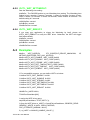
A.3 Examples
#define
WDT_CODE(ID)
CTL_CODE(FILE_DEVICE_UNKNOWN,
METHOD_BUFFERED, FILE_ANY_ACCESS)
#define IOCTL_WDT_ENABLE WDT_CODE (0x900)
#define IOCTL_WDT_DISABLE WDT_CODE (0x901)
#define IOCTL_WDT_STROBE WDT_CODE (0x902)
#define IOCTL_WDT_GET_TIMEOUT WDT_CODE (0x903)
#define IOCTL_WDT_SET_TIMEOUT WDT_CODE (0x904)
#define IOCTL_WDT_REBOOT WDT_CODE (0x905)
// For compatibility reasons, you can define IOCTL as below:
// #define IOCTL_WDT_ENABLE 0x1001
// #define IOCTL_WDT_DISABLE 0x1002
// #define IOCTL_WDT_STROBE 0x1003
// #define IOCTL_WDT_GETTIMEOUT 0x1004
// #define IOCTL_WDT_SETTIMEOUT 0x1005
// #define IOCTL_WDT_REBOOT 0x1006
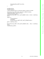
HANDLE m_hWDT=NULL;
TCHAR szClassName[66];
// assign the WDT driver name
wsprintf(szClassName, TEXT("WDT1:"));
// Open the WDT driver m_hWDT = CreateFile(szClassName, GENERIC_READ
GENERIC_WRITE, 0, NULL, OPEN_EXISTING,
FILE_ATTRIBUTE_NORMAL, NULL);
if ( m_hWDT == INVALID_HANDLE_VALUE ) {
TPC-31/61 User Manual
42
ID,
}
DWORD dwTemp;
DWORD nIndex=2;
// Set the Watchdog Timer as 10 seconds. Number 2 means 10 seconds.
DeviceIoControl(m_hWDT, IOCTL_WDT_SET_TIMEOUT, &nIndex,
sizeof(nIndex), NULL, 0, &dwTemp, NULL);
// Enable the Watchdog timer
DeviceIoControl(m_hWDT, IOCTL_WDT_ENABLE, NULL, 0, NULL, 0, &dwTemp,
NULL);
While (1) {
// do your job here°¦
Sleep(8000);
DeviceIoControl(m_hWDT, IOCTL_WDT_STROBE, NULL,0,
NULL, 0, &dwTemp, NULL);
}
DeviceIoControl(m_hWDT, IOCTL_WDT_DISABLE, NULL, , NULL, 0, &dwTemp,
NULL);
CloseHandle(m_hWDT);
43
TPC-31/61 User Manual
Appendix A Watchdog Timer Programming
DebugMsg(CString("WDT driver fail"));
return;
TPC-31/61 User Manual
44
Appendix
B
B
Fuse Specifications
B.1 Fuse Specifications
Rating: 250 VAC, 1A
Note!
The fuse is set to break if the input voltage exceeds 32VDC.
TPC-31/61 User Manual
46
Appendix
C
C
Pin Assignments
C.1 RS-232 Pin Assignments-TPC-31/TPC-61
(COM1,COM2)
Pin No.
Description
Pin 1
DCD
Pin 2
Rx
Pin 3
Tx
Pin 4
DTR
Pin 5
GND
Pin 6
DSR
Pin 7
RTS
Pin 8
CTS
Pin 9
RI
C.2 RS-485 Pin Assignment - TPC-31
Pin No.
Description
Pin 1
No Connection
Pin 2
DATA +
Pin 3
DATA -
Pin 4
No Connection
Pin 5
GND
Pin 6
No Connection
Pin 7
No Connection
Pin 8
No Connection
Pin 9
No Connection
TPC-61 (COM3)
Pin No.
Description
Pin 1
DATA -
Pin 2
DATA +
Pin 3
No Connection
Pin 4
No Connection
Pin 5
GND
Pin 6
No Connection
Pin 7
No Connection
Pin 8
No Connection
Pin 9
No Connection
TPC-31/61 User Manual
48
Pin No.
Description
Pin 1
TX-
Pin 2
TX+
Pin 3
RX+
Pin 4
RX-
Pin 5
GND
Pin 6
No Connection
Pin 7
No Connection
Pin 8
No Connection
Pin 9
No Connection
49
TPC-31/61 User Manual
Appendix C Pin Assignments
C.3 RS422(COM3) Pin assignment - TPC-61
TPC-31/61 User Manual
50
Appendix
D
Visual Settings
D
There are two powerful and friendly utilities included to extend the visual capabilities
of TPC-31T/61T. The two utilities are used to set the font size and rotate the screen.
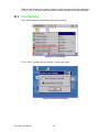
D.1 Font Setting
Go to start->programs->advantech->system font setting.
Figure D.1 Font Setting
TPC-31T/61T provides two font settings - normal and small.
Figure D.2 Small Font Setting
TPC-31/61 User Manual
52
Appendix D Visual Settings
Figure D.3 Change Font Setting
Figure D.4 Small Font Display
53
TPC-31/61 User Manual
D.2 Screen Rotation
Go to start->setting->control panel-> screen rotation as below.
Figure D.5 Screen Rotation
Select how you want the view display.
Figure D.6 Screen Rotation Options
TPC-31/61 User Manual
54
Appendix D Visual Settings
This screen is rotated 90 degrees in the example.
Figure D.7 90 Degrees Rotation
Figure D.8 Portrait Rotation
55
TPC-31/61 User Manual
TPC-31/61 User Manual
56
Appendix
E
E
TPC-31T /61T Update
Guide
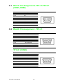
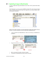
E.1 Updating Image & Bootloader
In order to update the image & bootloader for the TPC-31T/61T, please follow below
guideline:
Click "My device", you can see two HardDisk (external SD card & internal storage)
inside. HardDisk2 (External SD Card) is the image file source while HardDisk (Internal Storage) is destination.
There are three files needed for image and bootloader update (MLO, EBOOTST.nb0,
NK.nbl). You need to copy them to an SD card before updating process.
1.
Copy new "MLO" and "EBOOTSD.nb0 " files to root directory of HardDisk from
HardDisk2.
2.
Copy new "NK.nbl" file to "WINCE" folder under HardDisk from HardDisk2
3.
4.
After a successful file update, reboot the system.
The system is initializing and will take around 3 minutes.
TPC-31/61 User Manual
58
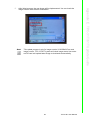
After initial success, the new image will be implemented. You can check the
image version under Version Information.
Note!
This update process is only for image version V3.03 B240.From next
image version, TPC-31T/61T system will check image status from external SD card and update latest image to bootloader automatically.
59
TPC-31/61 User Manual
Appendix E TPC-31T /61T Update Guide
5.
6.
The Boot Loader version can be checked at system power on stage.
TPC-31/61 User Manual
60
Appendix
F
F
Jumper & Dip Switch
Setting List
F.1
TPC-31T Component construction
F.1.1 EAMB-2201 Top side
F.2
Jumper Setting DIP Switch
SW6
RS-232 /RS485 Selection
RS-485 Setting
SW6.5 Terminal
OFF (No Terminal)
RS-232 Setting
TPC-31/61 User Manual
62
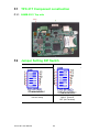
TPC-61T Component construction
Appendix F Jumper & Dip Switch Setting List
F.3
F.3.1 EAMB-2200 Top side
F.3.2 EAMB-2200 Bottom side
63
TPC-31/61 User Manual
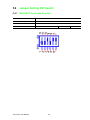
F.4
Jumper Setting DIP Switch
F.4.1 SW3 UART Controlled Function
SW3
Description
Default
UART Controlled Function
This switch is used to select UART Controlled Function
PIN6:URAT Mode Selection ON
UART Mode Selection SW3.6 RS485_422 Selection
TPC-31/61 User Manual
64
OFF(RS422)
ON(RS485)
Appendix F Jumper & Dip Switch Setting List
TPC-31/61 User Manual
65
www.advantech.com
Please verify specifications before quoting. This guide is intended for reference
purposes only.
All product specifications are subject to change without notice.
No part of this publication may be reproduced in any form or by any means,
electronic, photocopying, recording or otherwise, without prior written permission of the publisher.
All brand and product names are trademarks or registered trademarks of their
respective companies.
© Advantech Co., Ltd. 2012