1
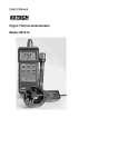
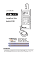
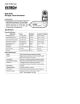
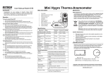
User's Manual
Hygro Thermo-Anemometer
Model 407412
Test Equipment Depot - 800.517.8431 - 99 Washington Street Melrose, MA 02176
FAX 781.665.0780 - TestEquipmentDepot.com
WARRANTY
EXTECH INSTRUMENTS CORPORATION warrants this instrument to be free of defects
in parts and workmanship for one year from date of shipment (a six month limited
warranty applies on sensors and cables). If it should become necessary to return the
instrument for service during or beyond the warranty period, contact the Customer
Service Department at (781) 890-7440 ext. 210 for authorization or visit our website at
www.extech.com (click on ‘Contact Extech’ and go to ‘Service Department’ to request an
RA number). A Return Authorization (RA) number must be issued before any product is
returned to Extech. The sender is responsible for shipping charges, freight, insurance
and proper packaging to prevent damage in transit. This warranty does not apply to
defects resulting from action of the user such as misuse, improper wiring, operation
outside of specification, improper maintenance or repair, or unauthorized modification.
Extech specifically disclaims any implied warranties or merchantability or fitness for a
specific purpose and will not be liable for any direct, indirect, incidental or consequential
damages. Extech's total liability is limited to repair or replacement of the product. The
warranty set forth above is inclusive and no other warranty, whether written or oral, is
expressed or implied.
Introduction
Congratulations on your purchase of Extech's Hygro Thermo-Anemometer. This Heavy
Duty meter measures and displays Air Velocity + Temperature and Relative Humidity +
Temperature. Air flow can be displayed in the following units of measure: feet per minute,
meters per second, miles per hour, kilometers per hour, and knots. Temperature and RH
o
o
units are displayed in C/ F and % units respectively. Careful use of this meter will provide
years of reliable service.
Specifications
General Specifications
Display
Dual function, 4-digit (9999 count) LCD display
Units of measure
m/s (meters per second), km/hr (kilometers per hour), ft/min (feet per
minute), knots (nautical miles per hour), mile/hr (miles per hour);
Temperature: °C/°F; Humidity: %RH
Data hold
Holds reading on the LCD display when button is pressed
Sensors
Air velocity sensor: Twisted vane arm with low friction ball bearing;
Temperature: Precision thermistor; Humidity: Thin film capacitor
Max/Min Record
Records highest and lowest readings for later recall
Data Output
RS-232 serial PC interface
Operating Temp.
32°F to 122°F (0°C to 50°C)
Operating Humidity
Max. 80% RH.
Power Supply
9V battery
Power Consumption Approx. 8.3 mA DC
Weight
0.77 lbs. (350g)
Dimensions
Meter: 7.1x2.8x1.3" (180 x 72 x 32mm);
Anemometer Probe: 0.7" (17mm) Diameter x 6.7" (170mm)
Accessories
Anemometer/temperature and RH Probes, 9V battery, & case
2
Model 407412 May 2003 Rev. 1.9
Range Specifications
Air velocity
Measurement
ft/min (feet/min)
Range
Resolution
Accuracy (% of reading)
80 - 4921 ft/min
1 ft/min
± (2% + 20 ft/min)
m/s (meters/sec)
0.4 - 25.00 m/s
0.01 m/s
± (2% + 0.2 m/sec)
km/h (kilometers/hour)
1.4 - 90.0 km/h
0.1 km/h
± (2% + 0.2 km/hr)
mph (miles/hour)
0.9 - 55.9 mph
0.1 mph
± (2% + 0.2 mph)
knots (nautical miles/hour ) 0.8 to 48.6 knots 0.1 knots
± (2% + 0.2 knots)
Temperature
Range
o
Resolution
o
o
o
o
32 F to 122 F (0 C to 50 C)
Accuracy
o
o
0.1 F/ C
o
±1.5 F (±0.8 C)
Relative Humidity
Range
Resolution
Accuracy
10 to 70% RH
0.1%
±3% RH
70 to 95% RH
0.1%
±4% RH
Meter Description
1.
LCD Display
2.
POWER button
3.
Data Hold button
4.
°C/°F Selection button
5.
Function switch
6.
Data Record button
7.
Data Recall button
8.
Units select button
9.
RS-232 output jack
9
10
Vane
Probe head
RH Probe head
1
3
4
5
2
6
7
8
Probe
Handles
11
(rear)
10. Probe input socket
Probe
Plugs
11. Battery compartment
3
Model 407412 May 2003 Rev. 1.9
Test Equipment Depot - 800.517.8431 - 99 Washington Street Melrose, MA 02176
FAX 781.665.0780 - TestEquipmentDepot.com
Anemometer and Temperature Operation
1.
Insert the Vane sensor into the meter's input jack at the top of the meter.
2.
Press the POWER button to turn the instrument on.
3.
Select 'Anemometer' operation by placing the function slider switch to the vane icon.
4.
Select the temperature units by pressing the °C/°F button. The LCD display will
indicate '°C' or '°F' as selected.
5.
Select the air velocity unit of measure by pressing the
UNIT button. With each press the display scrolls
through the units (m/s, km/hr, ft/min, knots, & mile/h).
6.
For maximum accuracy, the airflow must enter the vane
on the side without the yellow dot (see diagram).
7.
The meter’s LCD will indicate Air Velocity +
Temperature.
Yellow
Dot
airflow
Relative Humidity and Temperature Operation
1.
Insert the Relative Humidity probe in the input jack at the top of the meter.
2.
Press the POWER button to turn on the instrument.
3.
Select the Humidity mode of operation by placing the function slider switch to the
%RH position.
4.
Select the temperature units by pressing the °C/°F button. The LCD display will
indicate '°C' or '°F' as selected.
5.
Hold the probe by the handle and point it in the area to be measured. The meter will
display Relative Humidity + Temperature.
6.
Note that humidity measurements take several minutes to stabilize.
Data Hold
Press the DATA HOLD button to freeze the displayed reading. The DH icon will appear on
the LCD while Data Hold is engaged. Press the DATA HOLD button again to resume
normal operation.
Min/Max Record Mode
When selected, the Record mode stores the highest (Max) and lowest (Min) readings for
later recall. To use Record mode:
1. Press the RECORD button. The REC indicator will appear on the LCD display.
2.
Start a measurement session.
3.
After the measurement session, press the RECALL button to view the highest (Max)
reading recorded since the RECORD button was pressed. The MAX indicator will
appear to inform the user that the displayed reading is the highest value recorded.
4.
Press the RECALL button again to view the lowest reading encountered since the
RECORD key was pressed (the MIN indicator will appear on the LCD to inform the
user that the reading displayed is the lowest value recorded).
5.
Press RECORD again to return the meter to normal operation. All stored data will be
cleared and the REC/MIN/MAX icons will disappear from the LCD.
6.
Note that putting the meter into the Record mode defeats the Auto Power Off feature.
4
Model 407412 May 2003 Rev. 1.9
RS-232 PC Interface
The RS-232 serial data port (3.5mm phono jack) is located at the top of the meter next to
the sensor input jack. The PC interface hardware is intended for use with the Extech Data
TM
Acquisition software package, Part Number 407001 which includes Windows 95 / 98 /
ME / NT / 2000 compatible software and PC interface cable. For more information, contact
Extech or refer to the 407001 User's Manual.
Auto Power Off feature
The Auto Power Off feature automatically turns the meter off after approximately 10
minutes. To defeat this feature, place the meter in Record mode by pressing the RECORD
key once (the REC icon will appear on the LCD). The meter will remain powered as long
as the meter is in the RECORD mode.
Battery Replacement
When it is time to replace the 9V battery, the low battery indicator (LBT) appears in the lefthand corner of the LCD display. Note that reliable readings can be obtained for several
hours after the first appearance of the low battery indicator.
To replace the battery:
1. Remove the meter's protective rubber holster.
2. Pry off the battery compartment cover on the rear of the meter using a small coin or
screwdriver.
3. Replace the 9V battery and reinstall the compartment cover and holster.
Relative Humidity Calibration
1. Turn the meter on and select the Humidity mode using the slide switch.
2. Use a simulator to apply 0.0 ºC to the meter and adjust VR3 for a display of 0.0 ºC.
3. Change the input to 25.0 ºC and adjust VR1 for a display of 25.0 ºC.
4. Change the input to 50.0 ºC and verify a display of 50.0 ºC. Readjust VR3 & VR1 if
necessary.
5. Connect the humidity probe to the unit and place the probe in a controlled 33% RH
environment. Let stabilize for a minimum of 30 minutes and adjust VR5 for a reading of
33.0% RH.
6. Place the probe in a 75% RH environment for a minimum of 30 minutes and adjust “R6
for a reading of 75.0% RH.
7. Verify that the temperature reading is within the published specifications. If not, perform
calibration steps 2 and 3, above, again.
5
Model 407412 May 2003 Rev. 1.9
Appendix
Area equation for rectangular or square ducts
Height (H)
Area (A) = Width (W) x Height (H)
Width (W)
Area equation for circular ducts
Area (A) = 6 x r2
Where 6 = 3.14 and r2 = radius x
radius
Radius
Cubic equations
CFM (ft3/min) = Air Velocity (ft/min) x Area (ft2)
CMM (m3/min) = Air Velocity (m/sec) x Area (m2) x 60
NOTE: Measurements made in inches
must be converted to feet or meters before using the above formulae.
Unit of Measure Conversion Table
m/s
ft/min
knots
km/h
MPH
1
196.87
1.944
3.6
2.24
1 ft/min
0.00508
1
0.00987
0.01829
0.01138
1 knot
0.5144
101.27
1
1.8519
1.1523
1 km/h
0.2778
54.69
0.54
1
0.6222
1 MPH
0.4464
87.89
0.8679
1.6071
1
1 m/s
7
Model 407412 May 2003 Rev. 1.9
Test Equipment Depot - 800.517.8431 - 99 Washington Street Melrose, MA 02176
FAX 781.665.0780 - TestEquipmentDepot.com