1
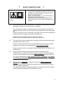
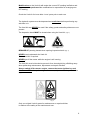
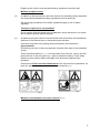
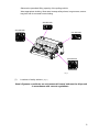
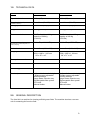
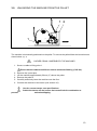
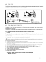
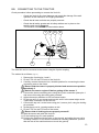
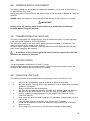
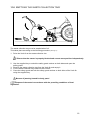
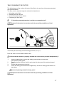
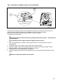
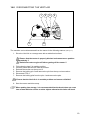
User manual and parts book Verti-Air 120 - 160 Serial number: Translation of the original user manual NOTE: IN THE INTERESTS OF SAFETY AND ACHIEVING THE BEST RESULT, IT IS VERY IMPORTANT THAT THIS MANUAL IS READ CAREFULLY BEFORE USING THE VERTI-AIR. 1052 Dutch 945.120.204 FOREWORD Congratulations with the purchase of your Verti-air. This manual must be read and understood in order to ensure safe and long-term operation of this Verti-Air. Safe operation of this machine is not possible if the user is not fully familiar with the content of this manual. The Verti-Air is not a stand-alone machine. It is the responsibility of the user to use the correct tractor. The user also has to perform safety-related checks on the tractor/Verti-Air combination including sound level, user instructions and risk analysis. The general safety instructions will be covered on the next page. All users must be familiar with and apply these instructions. There is a registration card below, which must be sent back in order to process any future claims. This user manual contains numerous instructions, which are numbered in sequence. This working sequence must be adhered to. The pictogram pictogram indicates safety instructions. The indicates a tip and/or note. All information and technical specifications used were the most recent at the time of publication. Design specifications are subject to change without notice. This document is a translation of the original user manual. Original user manual (Dutch language) is available on request. WARRANTY CONDITIONS THIS VERTI-AIR IS SUPPLIED WITH A WARRANTY FOR DEFECTS IN MATERIALS. THIS WARRANTY IS VALID FOR A PERIOD OF 12 MONTHS FROM THE DATE OF PURCHASE. VERTI-AIR WARRANTIES ARE SUBJECT TO THE “GENERAL CONDITIONS FOR SUPPLY OF PLANT AND MACHINERY FOR EXPORT, NUMBER 188”, WHICH WERE PUBLISHED UNDER THE AUSPICES OF THE UNITED NATIONS ECONOMIC COMMISSION FOR EUROPE. REGISTRATION CARD Complete the table below for your own records: Machine serial number Dealer name Purchase date Comments 2 ! Fig. 1 (1) SAFETY INSTRUCTIONS ! The Verti-Air is designed for safe use. This is only possible if the safety instructions defined in this manual are observed in full. Read and understand (Fig. 1) the manual before proceeding to use the Verti-Air. Failure to use the machine as described in the manual can result in injury and/or damage to the Verti-Air. Use of the machine requires operation by a competent user who has proficiently adjusted the machine to suit the surface for treatment. The manufacturer accepts no liability whatsoever for incompetent use and any damage arising from this; the user bears full responsibility for all risks arising from this. Failure to execute the user, maintenance and repair instructions prescribed by the manufacturer also constitutes improper/incompetent use. Inspect the area for treatment prior to using the Verti-Air. Remove any free-standing obstacles and avoid irregularities. (2) The Verti-Air has been manufactured in accordance with the latest technological knowledge and is safe for use. There is a risk of injury for the user and third parties if the machine is operated, maintained or repaired by improper persons. This must be avoided! Always use the Verti-Air in combination with the correct tractor, as defined in the technical data. (3) All persons appointed by the owner as authorised to operate, perform maintenance on or repair the Verti-Air must have read and fully understood the content of the operation manual and the Safety guidelines section in particular. The user is responsible for a safe Tractor/ Verti-Air combination. The system as a whole must be tested for sound, safety, risk and ease of use. User instructions must also be drawn up. (4) The user has an obligation to check the Verti-Air for visible damage and defects before use. Changes to the Verti-Air (including the operation) that are detrimental to safety must be rectified immediately. For safety-based reasons, adapting or adding to the Verti-Air (with the exception of factory approved changes) is not permitted as a rule. 3 Modifications to the Verti-Air will render the current CE marking ineffective and the person who performed the modifications is responsible for arranging new CE marking. Check the Verti-Air for loose bolts / nuts / parts prior to each use. The hydraulic system must be depressurised at all times before performing any activities on it. The Verti-Air may NEVER be used if the safety guards and safety stickers are not present. The inspection hatch MUST be closed when using the Verti-Air. (Fig. 2) Fig. 3 Fig. 2 BEWARE OF jamming hazard when opening inspection hatch (Fig. 3). NEVER crawl underneath the Verti-Air. Tilt the Verti-Air if required. NEVER get off the tractor while the engine is still running. The Verti-Air must be blocked to prevent it from lowering/driving off/sliding away when performing maintenance, adjustment and repair activities. Always switch off the tractor engine, remove the tractor ignition key and disconnect PTO when performing maintenance, adjustment and repair activities (Fig.4) Fig. 4 Only use original Verti-Air parts for maintenance or repair activities in relation to the safety of the machine and user. 4 Repairs to the Verti-Air must be performed by authorised, technical staff. Maintain a repairs record. (5) In addition to the instructions in this user manual, the prevailing safety standards and Occupational Health and Safety regulations must be observed. The governing procedures of the traffic regulations apply to use on public highways. Transport of persons is not permitted! Do not use the Verti-Air during hours of darkness, heavy rain/storm or on slopes with a gradient greater than 20 degrees. (6) All persons using the Verti-Air must be familiar with all functions and operational elements of the machine prior to commencing the activities. Connect the Verti-Air to the pulling vehicle as stated in the instructions. (Injury hazard!) Ensure that you have a clear long distance view and clear sight of the immediate vicinity. There are safety stickers (Fig. 4, 5, 6) on both sides of the Verti-Air, one on the side panel and one on the rear guard (Fig. 7) with an identical meaning. These safety stickers must be clearly visible and legible at all times and replaced when damaged. Persons must STAY out of the hazard zone of the Verti-Air when operational, as there is a physical injury hazard due to airborne material (Fig. 5). Fig. 5 Fig. 6 Maintain a safe distance of at least 4 metres! (Fig. 6) 5 Observe the permitted lifting capacity of the pulling vehicle. Wear appropriate clothing. Wear steel toecap safety shoes, long trousers, secure long hair and do not wear loose clothing. 900.280.402 933.280.402 911.280.404 933.280.402 Fig. 7 (7) Locations of safety stickers. (Fig. 7) Used oil/grease constitutes an environmental hazard and must be disposed in accordance with current regulations. 6 EU-DECLARATION We, Redexim BV Utrechtseweg 127 3702 AC Zeist, the Netherlands declare entirely under our own responsibility that the product: VERTI-GROOM WITH MACHINE NUMBER AS STATED ON THE MACHINE AND IN THIS MANUAL, to which this statement relates, is in accordance with the provisions of the Machine Directive 2006/42/EG. Zeist, 01/10/09 A.C. Bos Manager Operations & Logistics Redexim Holland 7 TABLE OF CONTENTS GEBRUIKERSHANDLEIDING EN ONDERDELENBOEK FOUT! BLADWIJZER NIET GEDEFINIEERD. EU-VERKLARING ...................................................................................................... 7 1.0 TECHNISCHE GEGEVENS ............................................................................ 9 2.0 ALGEMENE BESCHRIJVING ......................................................................... 9 3.0 DE MACHINE VAN DE PALLET HALEN ......................................................10 4.0 DE PTO ..........................................................................................................11 4.1 DE LENGTE VAN DE PTO ............................................................................11 4.2 GEBRUIK VAN DE PTO ................................................................................12 4.3 PTO INFORMATIE EN ONDERHOUD ...........................................................12 5.0 AANKOPPELEN AAN DE TRACTOR ...........................................................13 6.0 WERKDIEPTE VERSTELLING ......................................................................13 7.0 TRANSPORT VAN DE VERTI-AIR ................................................................14 8.0 DE RIJSNELHEID ..........................................................................................14 9.0 HET GEBRUIK VAN DE VERTI-AIR ..............................................................14 10.0 START/STOP PROCEDURE .........................................................................15 11.0 LEGEN VAN DE VUILOPVANGBAK.............................................................16 12.0 REINIGEN VAN HET FILTER ........................................................................17 13.0 HOEKVERSTELLING VAN DE SCHUDZEEF ...............................................18 14.0 HET AFKOPPELEN VAN DE VERTI-AIR ......................................................19 15.0 PROBLEEM ANALYSE .................................................................................20 16.0 ONDERHOUD ................................................................................................21 17.0 V-SNAAR VERSTELLING .............................................................................22 8 1.0 TECHNICAL DATA Model VERTI-AIR 120 VERTI-AIR 160 Operational width 1.20 m (47”) 1.60 m (63”) Operational depth (With no wear 0mm-26mm (0”-1.02”) 0mm-26mm (0”-1.02”) Driving speed Max. 8 Km/h (5 mph) Max. 8 Km/h (5 mph) Weight 350 Kg (772 lbs) 425 Kg (937 lbs) Recommended tractor 25 HP with minimal lifting capacity of 500 Kg (1102 lbs) 35 HP with minimal lifting capacity of 600 Kg (1323 lbs) Maximum capacity 9600 m2/h (103333 ft2/h) 12800 m2/h (137778 ft2/h) Mesh size shaker screen 5mm x 5mm (0.2 “ x 0.2”) 5mm x 5mm (0.2 “ x 0.2”) Shipping dimensions LxWxH 1500 x 1400 x 1,100 mm 59” x 55” x 43” LxWxH 1500 x 1800 x 1,100 mm 59” x 71” x 43” Three-point connection CAT. 1 CAT. 1 Gearbox oil SAE 90 SAE 90 Lubricating grease EP 2 EP 2 Standard parts - Adjustable front roller height. - Shaker screen adjustable cleaning settings. -Large waste collection tray. -Exchangeable filter system -PTO-axle -Manual holder. - Adjustable front roller height. - Shaker screen adjustable cleaning settings. -Large waste collection tray. -Exchangeable filter system -PTO-axle -Manual holder. and tear on brush) (Theoretical at maximum speed; 12 Km/h (7.5mph)) 2.0 GENERAL DESCRIPTION The Verti-Air is a machine for cleaning artificial grass fields. The machine also has a vacuum unit for extracting dirt from the field. 9 3.0 UNLOADING THE MACHINE FROM THE PALLET 1 2 1 Fig. 8 The machine is horizontally positioned on the pallet. To remove the pallet follow the instructions as shown below :(Fig. 8) !! NEVER CRAWL UNDERNEATH THE MACHINE!! 1. Secure a cable to lifting point 1. Ensure that the cable/crane/lift can hoist a minimum of 600 kg (1323 lbs). 2. 3. 4. 5. Remove the 3 point pins. Lift the machine approximately 50 mm (2") above the pallet. Remove the pallet 2. Carefully and slowly lower the machine onto the floor. 6. Connect the machine to the tractor (see section 4.0). Use the correct tractor; see specifications. prevent Switch the tractor off and secure the tractor/Verti-Air combination to activation/slipping. 10 4.0 THE PTO The PTO is a very important part (Fig. 9). It provides the drive from the tractor and ensures, if correctly maintained and installed, safe use of the machine. The PTO has dedicated CE certification. Read the PTO manual, which can be found on the actual PTO. Fig. 9 4.1 THE LENGTH OF THE PTO The length of the PTO is very important (Fig. 9). The drive on the tractor and/or Verti-Air can become damaged if this is too long. The PTO can be damaged if the length of the tube overlap exceeds 150 mm (6") at any given time. !! The length changes when the machine is lifted or if another tractor is used. The procedure for correctly adjusting the length of the PTO if newly purchased or if another tractor is used is as follows: 1. Connect the Verti-Air to the tractor as described in section 5.0. !! Switch the tractor off and ensure that the tractor is properly blocked and cannot move position independently!! 2. Lower the Verti-Air until the front roller is on the ground. 3. Measure the distance A between the PTO connection on the tractor and the Verti-Air connection, from groove to groove. 4. Measure the length B of the PTO when in the shortest position from locking pin to locking bolt. 5. Split the PTO into two parts and remove the safety guards from both ends. 6. Both the ends of the tubes and the safety guards must be shortened. (B-A) + 75 mm (3”). 7. Burr all parts, use a little grease and reassemble all parts. 8. Fit the PTO to the Verti-Air side. 9. Secure the other end of the PTO to the tractor. 10. Check the tube overlap. !! Never use the machine if the PTO safety guard is damaged: Replace this first. !! 11 4.2 USING THE PTO Correct use of the PTO requires checks of the following items: 1. When operational, the angle of the centres of rotation may never exceed 30 degrees. 2. The centres of rotation must always be aligned. 3. The minimum tube overlap is 150 mm. 4. Never use the machine if the PTO safety guard is damaged. 4.3 PTO INFORMATION AND MAINTENANCE Abridged maintenance schedule PTO. Periodic maintenance: Grease the lubricating points every 100 operational hours or after a long period of inactivity. Check the PTO for any damage to the safety guards and replace these if they are no longer sound. Check that the safety stickers are in place on the PTO and are not damaged. Annual maintenance: Remove the PTO from the machine. Inspect the PTO parts. All damaged parts must be replaced. Arrange all parts and carefully inspect them. Replace any damaged or worn parts. Clean all grip connections between parts. Reassemble all parts. Grease both tubes and reassemble both PTO parts. Reassemble the PTO and fit it to the machine. See the manual supplied with the PTO for additional information about maintenance and dismantling the PTO. The gearbox may be exposed to a higher load if the PTO has been shortened incorrectly or another tractor is used. This can cause damage. 12 5.0 CONNECTING TO THE TRACTOR Check procedure before proceeding to connect the Verti-Air. Check the Verti-Air for visual damage and repair this damage if the safe operation of the machine is no longer guaranteed. Check that all nuts and bolts are properly secured. Check that all safety guards and all safety stickers are in place on the machine and are not damaged. The machine must NEVER be used without these. 1 5 2 3 4 6 Fig. 10 The Verti-Air can be connected to the tractor using the 3 point coupling. The method is as follows: (Fig. 10) 1. Remove the 3 point pins 1 and 2 2. Fit the PTO 4 to the PTO axle of the Verti-Air 3. Carefully reverse the tractor into a suitable position for connecting the lower connecting arms to the frame. !! Ensure that the tractor is properly blocked and cannot move position independently !! 4. 5. 6. 7. 8. 9. !! Switch the tractor engine off before getting off the tractor !! Connect the lower connecting arms using the 3 point connection plate pins 1 and secure this using the locking pins provided. Adjust the tractor stabilizer to 100 mm lateral stroke. Fit the top rod 3 of your tractor and turn this until it is the same height as the 3-point stop connection on the Verti-Air. Connect the top rod 3 to the frame using pin 2; secure pin 2 using the locking pin provided. Screw the top rod in, creating tension on this. Fit the PTO 4 to the PTO axle of the tractor. !! Ensure that all locking pins are properly secured!! 10. Start the tractor and raise the Verti-Air. 11. Fit the bracing legs 5 in work position. 12. Position the machine with the roller on the ground, and adjust the top rod by screwing it either in or out until the machine is vertically positioned. (ensure that the rear of the machine does not touch the ground) 13 6.0 WORKING DEPTH ADJUSTMENT The working depth can be adjusted by rotating the spindles 6 on the front of the machine 10) to reposition the front roller. Adjust both sides of the machine to the same height, so that the field is cleaned as evenly as possible. NEVER adjust the machine in a way that will cause damage to the surface to be treated. ! IMPORTANT! Initially check the working depth on the surface to be treated from a stationary position, before using the machine! 7.0 TRANSPORTING THE VERTI-AIR The user is responsible for transporting the Verti-Air behind the tractor on public highways. Look into national legislation for the regulations. The maximum speed across open fields, with the machine elevated, is 20 km/hour (12.4 mph), on account of the weight of the Verti-Air. Driving at higher speeds constitutes a potential hazard for the driver/bystanders and may even cause damage to the machine. A minimum of 20% of the weight of the tractor must be supported on the front axle when the machine is elevated. 8.0 DRIVING SPEED The driving speed is restricted to 12 km/h (7.5 mph). Driving at higher speeds is not recommended in relation to excessive wear and tear and damage to the machine and the surface to be treated. 9.0 USING THE VERTI-AIR The following checks must be made before proceeding to use the Verti-Air at a site: 1. 2. 3. 4. 5. 6. 7. 8. Are there any freestanding objects on the field? Remove these first. Are there slopes? This machine is only suitable for use on slopes with a maximum gradient of 20 degrees. Always work from the top to the bottom. Are there are any airborne objects in the area, such as balls, which will distract the user from the task at hand? If so, then the Verti-Air may NOT be used. Is there a slipping or sagging hazard? If yes, postpone the activities until the conditions improve. Best results are achieved when working in dry conditions. Postpone the activity if it is too wet. If the machine vibrates excessively, then reduce the PTO speed. A field can be treated 2 or 3 times in identical or varying directions to facilitate better cleaning. Do not make any sharp turns as this may cause damage to the surface. 14 10.0 START/STOP PROCEDURE The start procedure is VERY important. The surface to be treated can be seriously damaged if this procedure is not executed as described below. The start procedure is as follows: 1. Thoroughly check the Verti-Air for loose parts and check that all parts are working properly. !! If loose parts are discovered or incorrectly functioning parts, then the problem must be rectified before using the Verti-Air !! 2. Drive to the site to be treated. 3. Adjust the working depth of the machine from a stationary position as described in section 6.0. !! Ensure that the tractor is properly blocked and cannot move position independently !! !! Switch the tractor engine off before getting off the tractor !! 4. 5. 6. 7. 8. 9. Lower the machine until it is suspended approximately 50 mm above the ground. Put the tractor into the correct gear. Switch on the PTO at a low motor speed. Increase the speed to ± 540 RPM Drive the tractor forwards and smoothly lower the Verti-Air onto the preset bottom roller. Increase the driving speed up to a maximum of 12 Km/h (7.5 mph). Stopping takes place as follows: 1. While driving, smoothly lift the machine until it is suspended approximately 50 mm above the ground. 2. Switch off the PTO and lift the machine higher. 3. Drive to the following site and start the process as described above. 15 11.0 EMPTYING THE WASTE COLLECTION TRAY Fig. 11 The waste collection tray must be emptied when full. This takes place according to the following procedure (See Fig.11): 1. Drive the Verti-Air to the waste collection site. !! Ensure that the tractor is properly blocked and cannot move position independently !! 2. Use the supplied key to unlock the safety guard catches on both sides and open the safety guard. 3. Remove the waste collection tray from the Verti-Air and empty it. 4. Put the waste collection tray back into the Verti-Air. 5. Close the safety guard and lock the safety guard catches on both sides of the Verti-Air using the supplied key. Beware of jamming hazard for body parts! Dispose of the waste in accordance with the prevailing conditions of local legislation. 16 12.0 CLEANING THE FILTER The effectiveness of the suction will reduce if the filter in the suction unit becomes saturated with collected waste. The filter must be cleaned using the methods indicated below: 1. 2. 3. 4. Knocking out the filter Blowing through using air Suction using a vacuum cleaner Replacing the filter fabric !!! Consider personal protection in relation to released dust !!! Dispose of the waste in accordance with the prevailing conditions of local legislation. Fig. 12 This takes place according to the following procedure (See Fig.12): Drive the Verti-Air to the waste collection site. !! Ensure that the tractor is properly blocked and cannot move position independently !! 1. 2. 3. 4. Use the supplied key to unlock the safety guard catches on both sides, and open the safety guard. Remove the filter from the Verti-Air and clean this using one of the methods stated above. Put the filter back into the Verti-Air. Close the safety guard and use the supplied key to lock the safety guard catches on both sides. Beware of jamming hazard for body parts! Dispose of the waste in accordance with the prevailing conditions of local legislation. 17 13.0 SHAKER SCREEN ANGLE ADJUSTMENT 2 1 Fig. 13 If an excess of material is held in the collection tray that has not yet been sieved, then the options include extending the time for the shaker screen to sieve the material. This can be achieved by positioning the shaker screen at an angle. This takes place as follows: !! Ensure that that tractor/Verti-Air is properly blocked and cannot move position independently !! !! Switch the tractor engine off before getting off the tractor !! 1. Use the supplied key to unlock the safety guard catches on both sides and open the safety guard. 2. Loosen the nuts 1 (by a single turn) on both sides of the machine. 3. Adjust the shaker screen 2 by repositioning it up or down to the desired angle. Ensure that the shaker screen angle always increases to the rear. 4. Tighten the nuts 1 on both sides of the machine. 5. Close the safety guard and use the supplied key to lock the safety guard catches on both sides. Beware of jamming hazard for body parts! 18 14.0 DISCONNECTING THE VERTI-AIR 1 5 2 3 4 6 Fig. 14 The machine can be disconnected from the tractor in the following manner (See Fig 14): 1. Drive the Verti-Air to a storage area with a stable/level surface. !! Ensure that the tractor is properly blocked and cannot move position independently !! !! Switch the tractor engine off before getting off the tractor !! 2. 3. 4. 5. 6. 7. Fit the bracing legs 5 in parking position. Carefully lower the Verti-Air onto the surface. Release the tension on the top rod 3. Remove the locking pin 2 and remove the pin from the top rod connection. Disconnect PTO 4. Remove the locking pins from the pins 1 and remove the pins. !! Ensure that the Verti-Air is in a stable position and cannot roll/slide!! 8. Start the tractor and drive away. When putting into storage, it is recommended that the brush does not come into contact with the surface or other objects otherwise the hairs will bend. 19 15.0 TROUBLESHOOTING Problem Excess of material for cleaning is held in waste collection tray Possible cause Solution Driving speed too slow. Increase driving speed. Working depth setting is too deep. Decrease depth setting on machine Shaker screen is blocked. Clear shaker screen. Shaker screen setting too level Adjust shaker screen angle. Lower brush speed by lowering PTO speed Brush speed too high Insufficient cleaning Working depth setting is not deep enough. Increase depth setting on machine Brush speed too low Increase PTO speed, which causes increase in brush speed Filter contaminated Clean filter Brush worn Replace brush Poor field appearance after treatment Machine depth setting is too deep. Decrease depth setting on machine Crunching sound when machine is operational Bearings require lubrication / are worn. Lubricate the bearings with an EP2 grease / replace the bearings. 20 16.0 MAINTENANCE Time schedule/frequency Checkpoint/Lubrication point Method Prior to each use Check for loose bolts / nuts. Tighten the loose bolts / nuts to the correct moment. Presence and legibility of the safety stickers. (Fig. 5) Replace if not present/damaged. Check for oil leaks Repair oil leak Check filters Clean filters if required Grease the roller bearings on the front roller Use EP 2 lubricating grease. After the first 20 operational hours (new or repaired) Check for loose bolts / nuts. Check for oil leaks in gearbox Tighten the loose bolts / nuts to the correct moment. Top up to edge of filling opening if required. Check filter After every 100 operation hours or annually Clean filter if required Grease the roller bearings on Use EP 2 lubricating grease. the front roller and the drive line. Check for oil leaks in gearbox Check the oil level in the gearbox Repair or replace. Top up to edge of filling opening if required. Check for loose bolts / nuts. Tighten the loose bolts / nuts with the correct moment. Check the tension of the V-belt / wear and tear. Adjust the V-belt tension or replace the V-belts where required. Check the brush for wear and tear. Replace brush if required. Inspect and lubricate PTO. See PTO manual. 21 17.0 V-BELT ADJUSTMENT 2 1 3 5 4 3 A A A A 5 4 3 5 Fig. 15 The Verti-Air is fitted with adjustable belt tensioners that maintain the stress on the V-belts. The drive line will be subjected to wear and tear through use. Therefore, the V-belts may start slipping and require tightening. The belt tensioners can be adjusted as follows (See Fig 15): !! Ensure that that tractor/Verti-Air is properly blocked and cannot move position independently !! !! Ensure that the PTO axle of the Verti-Air is disconnected!! 1. Remove all bolts 1 and the safety guard 2. 2. Loosen nut 3. 3. Loosen lock nut 4 slightly until the tension has just been released. 4. Adjust nut 5 and use this to adjust the tension on the V-belts by moving the bracket with the belt tensioners. 5. Check the V-belt tension by pulling on point A with a tension of 4.5 kg (9.9 lbs). The stretch must be 2 mm (0.08”). 6. Tighten lock nut 4. 7. Tighten nut 3. 8. Replace safety guard 2 and replace all nuts 1. 22