1
Helix Board 24 FireWire MKII
FireWire-enabled Mixing Console
IMPORTANT SAFETY INSTRUCTIONS
The apparatus shall not be exposed to dripping or splashing and that no objects
with liquids, such as vases,
shall be placed on the apparatus. The MAINS plug is used as the disconnect device, the disconnect device shall
remain readily operable.
Warning: the user shall not place this apparatus in the
can be easily accessible.
area during the operation so that the mains switch
1. Read these instructions before operating this
apparatus.
CAUTION
2. Keep these instructions for future reference.
RISK OF ELECTRIC SHOCK
DO NOT OPEN
3. Heed all warnings to ensure safe operation.
4. Follow all instructions provided in this document.
5. Do not use this apparatus near water or in locations
where condensation may occur.
6. Clean only with dry cloth. Do not use aerosol or liquid
cleaners. Unplug this apparatus before cleaning.
7. Do not block any of the ventilation openings. Install
in accordance with the manufacturer’s instructions.
CAUTION: TO REDUCE THE RISK OF ELECTRIC SHOCK,
DO NOT REMOVE COVER (OR BACK)
NO USER SERVICEABLE PARTS INSIDE
REFER SERVICING TO QUALIFIED PERSONNEL
The lightning flash with arrowhead symbol, within an
equilateral triangle, is intended to alert the user to the
presence of uninsulated “dangerous voltage” within the
product’
8. Do not install near any heat sources such as radiators,
heat registers, stoves, or other apparatus (including
.
9. Do not defeat the safety purpose of the polarized or
grounding-type plug. A polarized plug has two blades
with one wider than the other. A grounding type plug
has two blades and a third grounding prong. The wide
blade or the third prong is provided for your safety. If
the provided plug does not into your outlet, consult
an electrician for replacement of the obsolete outlet.
10. Protect the power cord from being walked on or
pinched particularly at plug, convenience receptacles,
and the point where they exit from the apparatus.
11. Only use attachments/accessories
manufacturer.
by the
12. Use only with a cart, stand, tripod, bracket, or
by the manufacturer, or sold with
table
the apparatus. When a cart is used, use caution
when moving the cart/apparatus
combination to avoid injury from tipover.
13. Unplug this apparatus during lighting
storms or when unused for long
periods of time.
service personnel.
14. Refer all servicing to
Servicing is required when the apparatus has been
damaged in any way, such as power-supply cord or
plug is damaged, liquid has been spilled or objects
have fallen into the apparatus, the apparatus has
been exposed to rain or moisture, does not operate
normally, or has been dropped.
magnitude to constitute a risk of electric shock to persons.
The exclamation point within an equilateral triangle is intended to alert the user to the presence of important operating and maintenance (servicing) instructions in the literature
accompanying the appliance.
WARNING: To reduce the risk of
or electric shock, do
not expose this apparatus to rain or moisture.
CAUTION: Use of controls or adjustments or performance
may result in
of procedures other than those
hazardous radiation exposure.
Helix Board 24 FireWire MKII
FireWire-enabled Mixing Console
INTRODUCTION .......................................................................................................................... 4
FEATURES................................................................................................................................... 4
PACKAGE INCLUDES ................................................................................................................. 5
GETTING STARTED .................................................................................................................... 5
CHANNEL SETUP ........................................................................................................................5
CONVERTING TO TABLE TOP MODE ........................................................................................6
INSTALLING THE RACK MOUNT KIT..........................................................................................7
MAKING CONNECTIONS ............................................................................................................8
INPUTS AND OUTPUTS ....................................................................................................8
MAIN MIXING PANEL ......................................................................................................10
CONTROLS AND SETTINGS .....................................................................................................10
REAR PANEL ...................................................................................................................10
CHANNEL CONTROLS ................................................................................................... 11
DIGITAL EFFECT SECTION.............................................................................................12
MASTER SECTION .........................................................................................................13
FIREWIRE PRE / POST SWITCHES ...............................................................................15
FIREWIRE INTERFACE..............................................................................................................16
SYSTEM REQUIREMENTS..............................................................................................16
DRIVER INSTALLATION...................................................................................................16
CHANNEL ASSIGNMENT.................................................................................................20
CUBASE LE .....................................................................................................................20
HELIX BOARD CONTROL PANEL ..................................................................................21
TROUBLESHOOTING ......................................................................................................23
DIGITAL EFFECTS TABLE ........................................................................................................24
APPLICATION .............................................................................................................................25
SPECIFICATIONS ......................................................................................................................27
DIMENSIONS..............................................................................................................................29
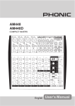
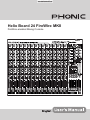
BLOCK DIAGRAM ......................................................................................................................30
Phonic preserves the right to improve or alter any information within this document without prior notice.
V1.0 SEP 11th,2006
INTRODUCTION
FEATURES
Thank you for purchasing the Helix Board 24 FireWire
MKII, one of Phonic’s newest mixers that sounds great
and works hard both in the studio and on the road. The
mixer features a FireWire interface that can stream up
to 18 independent channels of audio to the computer
and return two tracks for monitoring, all at screaming
fast transfer rates of up to 24-bit/96 kHz. Also featured
is an onboard 32/40-bit digital multi-effect processor
providing 100 popular programs plus tap delay, testtones and foot switch jacks. The multi-directional
Input/Output pod makes the device versatile; making
rack mounting or table-top connections much easier.
•
24-input analog mixer with extremely low noise
circuitry
•
96kHz FireWire interface for streaming 18
independent channels of audio to computer with
near-zero latency
•
Pre/post switches for swapping streaming input
channels to computer from pre low cut, EQ to post
EQ, post fader
•
2 channels of monitoring from computer via
FireWire interface, can be assigned to control
room monitors, main mix and AUX 1
•
');RXUELWKLJKGH¿QLWLRQDOJRULWKPGLJLWDO
multi-effect processor with 100 programs plus tap
delay and foot switch jacks
•
16 Mic/Line channels with inserts
•
3-band EQ with swept mid-range
•
+]ORZFXW¿OWHURQHDFKFKDQQHO
•
AUX 1 & 2 with Pre/Post switch
•
Six AUX send mixing bus
•
Four stereo AUX returns, three with effect to
monitor
•
+48V phantom power on Mic channels
•
Four true subgroups with main L and R routing
switches
•
Direct outputs for multi-track recording
•
Control Room and Phones outputs with multi-input
source matrix
•
0RQRRXWZLWKYDULDEOHORZSDVV¿OWHUIURP+]
to 160 Hz for subwoofer
•
Dual-position I/O pod
•
Built-in switching power supply with universal
connector, 100-240 VAC, 50/60 Hz
•
Rack-mounting kit included
•
44.1k S/PDIF digital audio output
•
Compatible with Mac OSX and Windows XP
•
Steinberg Cubase LE included
There are sixteen extremely low noise Mic preamps,
each with individual phantom power, and sixteen
1/4” phone jacks spread across the Helix Board 24
FireWire MKII 16 mono channels. Each channel
features a 3-band EQ (with a sweepable mid control),
$8;();DQG*URXSVHQGVDVZHOODVDORZFXW¿OWHU
for removing troublesome stage-rumble. Additional
features include AUX sends and returns, input and
output soloing, four true subgroups, dedicated Mono/
Subwoofer output with selectable Low Pass Filter, S/
PDIF digital outputs, Steinberg Cubase LE workstation
software and an included rack-mounting kit.
We know how eager you are to get started – wanting
to get the mixer out and hook it up to your computer
is probably your number one priority right now – but
before you do, we strongly urge you to take a look
WKURXJK WKLV PDQXDO ,QVLGH \RX ZLOO ¿QG LPSRUWDQW
instructions and warnings on the set up, use and
applications of your brand new Helix Board 24
FireWire MKII. If you do happen to be one of the many
SHRSOH ZKR ÀDWO\ UHIXVH WR UHDG XVHU PDQXDOV WKHQ
we just urge you to at least glance at the Instant Setup
and FireWire Interface sections. After glancing at or
reading through the manual (we applaud you if you do
read the entire manual), please store it in a place that
LVHDV\IRU\RXWR¿QGEHFDXVHFKDQFHVDUHWKHUH¶V
VRPHWKLQJ\RXPLVVHGWKH¿UVWWLPHDURXQG
4
Helix Board 24 FireWire MKII
PACKAGE INCLUDES
CHANNEL SETUP
1 x Helix Board 24 FireWire MKII mixer
1.
1 x FireWire cable
1 x CD-ROM with ASIO & WDM drivers
1 x CD-ROM with Steinberg Cubase LE
1 x Power cable
1 x Rack mounting kit
If any items are missing from your package, please
contact your local Phonic dealer
GETTING STARTED
1. Ensure all power is turned off on your mixer. To
totally ensure this, the AC cable should not be
connected to the unit.
2. All faders and level controls should be set at the
lowest level and all channels off to ensure no
sound is inadvertently sent through the outputs
when the device is switched on. All levels can be
altered to acceptable degrees after the device is
turned on using the channel setup instructions.
To ensure the correct audio level of the input
channel is selected, each of the Mixer’s Channel’s
ON buttons should be disengaged (which should
turn the corresponding LED indicator off), as
well as the Solo buttons on each channel and all
buttons in the Control Room Source section, with
exception to the Main L/R button.
2. Ensure the channel you wish to set has a signal
sent to it similar to the signal that will be sent when
in common use. For example, if the channel has
a microphone connected to it, then you should
speak or sing at the same level the performer
normally would during a performance; if a guitar
is plugged into the channel, then the guitar should
also be strummed as it normally would be (and so
on). This ensures levels are completely accurate
and avoids having to reset them later.
3. Move the Channel fader and Maser fader to around
the 0 dB mark.
4. Turn the Channel ON.
3. Plug any necessary equipment into the device’s
YDULRXVRXWSXWV7KLVFRXOGLQFOXGHDPSOL¿HUVDQG
speakers, monitors, signal processors, and/or
recording devices.
5. Pushing the channel’s Solo button and releasing
the Pre/Post button on the CTRL RM section will
send the pre-fader signal of the activated channel
to the Control Room / Phones mixing bus and the
Level Meter will display the Control Room’s signal
properties.
4. Plug the supplied AC cable into the AC inlet on the
back of the device and then into a power outlet of
a suitable voltage.
6. Set the gain so the level meter indicates the audio
level is around 0 dB (it is advisable to never let the
level exceed 7 dB).
5. Turn the power switch on and follow the channel
setup instructions to get the most out of your
equipment.
7. This channel is now ready to be used; you can stop
making the audio signal.
Helix Board 24 FireWire MKII
8. You can now repeat the same process for other
channels if you wish.
5
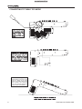
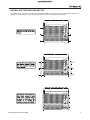
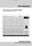
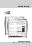
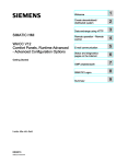
CONVERTING TO TABLE TOP MODE
When the connecting panel sits
perpendicular to the base of the
mixer, the design of the Helix
Board 24 FireWire MKII allows
uers to utilize it as a desk top
mixer, with a slightly angled face
to allow easier controllability.
6
Helix Board 24 FireWire MKII
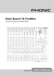
INSTALLING THE RACK MOUNT KIT
7RLQVWDOOWKHUDFNPRXQWNLWWRWKH+HOL[%RDUG)LUH:LUH0.,,WKHFRQQHFWLQJSDQHOVKRXOGEH¿UVWURWDWHGWRVLW
parallel to the mixer’s base. This is the optimal position for rack mounting, as it saves space.
Helix Board 24 FireWire MKII
7
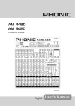
MAKING CONNECTIONS
6
5
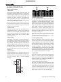
Inputs and Outputs
1. XLR Jacks
These jacks accept typical 3-pin XLR inputs for
balanced and unbalanced signals. They can be used in
conjunction with microphones – such as professional
condenser, dynamic or ribbon microphones – with
standard XLR male connectors, and feature low
QRLVH SUHDPSOL¿HUV VHUYLQJ IRU FU\VWDO FOHDU VRXQG
replication. The Helix Board 24 FireWire MKII features
a total of sixteen Microphone inputs.
NB. When these inputs are used with condenser microphones, the
Phantom Power should be activated. However, when Phantom Power
is engaged, single ended (unbalanced) microphones and instruments
should not be used on the Mic inputs.
2. Line In Jacks
This input accepts typical 1/4” TRS (balanced) or
TS (unbalanced) inputs, for balanced or unbalanced
signals. They can be used in conjunction with a wide
range of line level devices, such as keyboards, drum
machines, electric guitars, and a variety of other
electric instruments.
3. Insert Jacks
5. Auxiliary (AUX) Returns
The 1/4” TRS AUX Return inputs are for the return
of audio to the Helix Board 24 FireWire MKII mixer,
processed by an external signal processor. If really
needed, they can also be used as additional stereo
inputs. The feed from these inputs can be adjusted
using the AUX Return controls on the face of the
mixer. When connecting a monaural device to the
AUX Return 1, 2 and 4 inputs, simply plug a 1/4”
phone jack into the left (mono) input, and the signal
will appear in the right as well. This, however, does not
work for the AUX Return 3.
NB.When any device is plugged into the mixer’s corresponding EFX
Return inputs (AUX Return 3), the signal processed by the mixer’s
internal digital effect engine is then not fed to the Main L/R; the signal
fed into the EFX Return 3 inputs will be instead.
6. Auxiliary (AUX) Sends
The primary use for these 1/4” TRS phone jacks is
for the addition of external devices, such as dynamic
processors or equalizers, to the corresponding mono
input channel. This will require a Y cord that can
send and receive signals of the mixer to and from an
external processor. The tip of the TRS jack will send
the signal from the input channel, and the ring will
return the signal back to the mixer (the sleeve is the
grounding).
4. Direct Outputs
These connections are for the direct output of the
signals received by mono channels 1 through to 8,
post-fader, post-EQ, post-HPF, and post-mute. They
are most commonly used to connect multitrack
recorders.
3
7KHVH ´ 756 SKRQH MDFNV DUH WKH ¿QDO RXWSXW RI
line-level signal fed from the corresponding auxiliary
send mixing buses, and are best suited for use with
external effect processors or stage monitors. Feeding
WKHRXWSXWIURPWKH$X[LOLDU\RXWVWRDQDPSOL¿HUDQG
SRVVLEO\ DQ HTXDOL]HU DQG WKHQ WR D ÀRRU PRQLWRU
speaker allows artists to monitor their own instruments
or vocals whilst performing. The AUX 5 and AUX 6
Sends take their signal directly from AUX Controls 3
and 4, when the 5/6 Shift Button is activated.
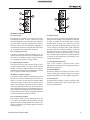
7. Group Outs
7KHVH´SKRQHMDFNVRXWSXWWKH¿QDOIHHGIURPWKH
Group 1, 2, 3 and 4 Faders on the main panel of the
mixer. These outputs can be used to feed multi-track
UHFRUGV DV ZHOO DV DQ DPSOL¿HU DQG VSHDNHUV WR EH
used along with the Main Speakers.
8. CTRL RM (Control Room) Output
2
1
These two 1/4” Phone Jack outputs feed the signal
altered by the Control Room level control on the face
of the mixer. This output has extensive use, as it can
be used to feed the signal from the mixer to an active
monitor, for the monitoring of the audio signal from
within a booth, among many other possible uses.
4
8
Helix Board 24 FireWire MKII
10
9
8
7
9. DSP Effect Output
These ports are for the immediate output of the EFX
signal, processed by the internal effect processor, the
level of which is not determined by the AUX 3 Return /
EFX control on the face of the mixer. This can be used
to send to external devices, for monitoring purposes,
or returned to a few channel on the Helix Board 24
FireWire MKII, and routed to the AUX 1, 2, and 4
outputs (the AUX 3 control must, of course, be turned
down to avoid forming a feedback loop), as well as the
Group Outs, allowing the processed signal to be sent
to multiple destinations for various applications.
10. Foot Switch Jacks
12. Main Outputs
7KHVH RXWSXWV ZLOO RXWSXW WKH ¿QDO VWHUHR OLQH OHYHO
signal sent from the main mixing bus. The primary
purpose of the two XLR jacks is to send the main
output to external devices, which may include power
DPSOL¿HUV DQG LQWXUQ D SDLU RI VSHDNHUV RWKHU
mixers, as well as a wide range of other possible
signal processors (equalizers, crossovers, etcetera).
The two 1/4” TRS phone jacks are able to send
the Main output to external devices that may run in
parallel with the mixer. This may include additional
SRZHU DPSOL¿HUV PL[HUV 3$ V\VWHPV DV ZHOO DV D
wide range of other possible signal processors.
13. Main Inserts
Located above each of the Main 1/4” Outputs, the
primary use for these 1/4” TRS phone jacks is for
the addition of external devices, such as dynamic
processors or equalizers, to the main L and main R
signals. This will require a Y cord that can send (prefader) and receive signals to and from an external
processor.
13
These ports are for the inclusion of a foot switch (nonlatchable), used to remotely adjust properties of the
built-in Digital Effect processor, to the mixer. The
uppermost jack is used to turn the device on and off,
where the lower jack is used for adjusting tap delay
properties.
11. Mono / Subwoofer Output
This XLR and 1/4” TRS output feeds a monaural
signal of the Main L-R signals combined or the AUX 4
signal (depending on the Mono Source Select Switch),
the level of which is adjusted by the accompanying
level control. This is ideal for use with a mono sound
system, or for the addition of a subwoofer to your set
of speakers, adding more punch to low frequency
sounds at your PA or monitoring system. Also featured
is an Insert point, allowing external devices, such as
a compressor, to be used to alter the mono signal
before it is fed through the outputs.
12
14. 2T Return
These inputs accommodate connections from RCA
cables, able to receive signals from such devices as
tape and CD players.
15. Record Outputs
As with the 2T Return ports, these outputs will
accommodate RCA cables, able to be fed to a variety
of recording devices.
17
11
Helix Board 24 FireWire MKII
16 15 14
9
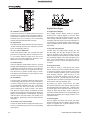
CONTROLS AND SETTINGS
Rear Panel
17
21. Power Switch
This switch is used to turn the mixer on and off. Ensure
you turn all level controls down before activating.
Activating the Power Switch will be accompanied
by an illuminated LED located above the right Level
Meter.
16 15 14
16. S/PDIF Output
This RCA S/PDIF (Sony / Phillips Digital Interface)
jack is for the output of digital audio signals, allowing
the Main L&R audio from the Helix Board 24 FireWire
MKII to be passed to another device without having
to convert the signal from digital to analog and back
again. The output sampling rate is set to 44.1 kHz per
second – however, if the FireWire interface is in use, it
will use the sampling rate decided by the Helix Board
control software.
17. FireWire Interface
These two FireWire ports are for connecting the
Helix Board 24 FireWire MKII to any PC or Macintosh
computer. They allow all 16 input channels, as well
as an additional channel (as decided by the FireWire
Select Switch), to be sent to a PC or Mac computer.
The main stereo signal of the computer is also
returned to the Helix Board 24 FireWire MKII. The
returned FireWire signal can be utilized by selecting
it in the Control Room Source section on the face of
the mixer.
22. Phantom Power
21 22
By turning this switch selector
to the ON position will activate
+48V of phantom power for the
corresponding microphone inputs,
allowing condenser microphones
(well, the ones that don’t use batteries) to be used on
these channels. Activating the master Phantom Power
switch will be accompanied by an illuminated LED
above the left channel Level Meter. Before turning
Phantom Power on, turn the level control down of the
channel you wish to activate to a minimum and lower
all master output levels, as to avoid the possibility of a
ghastly popping sound from the speakers.
NB. Phantom Power should be used in conjunction with balanced
microphones. When Phantom Power is engaged, single ended
(unbalanced) microphones and instruments should not be used
on the Mic inputs. Phantom Power will not cause damage to most
dynamic microphones, however if unsure, the microphone’s user
18. Power Connector and Fuse Holder
manual should be consulted.
This port is for the addition of a power cable and
supply, allowing power to be supplied to the mixer.
Please use the power cable that is
included with this mixer only. The
Fuse holder, located above the AC
Power connector, is, of course, for
Helix Board 24 FireWire MKII fuse.
If the fuse happens to blow, open
the holder cover, and replace the
fuse with a suitable replacement
(as indicated underneath the
power connector).
23. Mono Output Source Select Switch and Volume
Control
Main Mixing Panel
The mono output on the Helix Board 24 FireWire MKII
includes a Low Pass Filter (LPF) for removing high
frequency sounds to make the audio more appropriate
for use with subwoofers. The switch to the left turns
the LPF on and off, and the rotary control on the right
allows users to adjust the cut-off frequency between
60Hz and 160Hz.
18
19. 12V Lamp
This BNC socket allows you to attach a
12 Volt gooseneck lamp, allowing better
visibility in areas with poor light.
19
20. Phones Output
This output port is best suited for use with
headphones, allowing monitoring of the mix.
The audio level of this output is controlled
using the Phones control on the front panel’s
master section.
7KHURWDU\FRQWUROWRWKHULJKWDGMXVWVWKH¿QDORXWSXW
level of the Mono/Subwoofer output. By using the
switch on the left, users are able to select signal they
wish to send through the Mono/Subwoofer output
between the main mix and AUX 4 mix. If, for example,
there is audio in the main mix you do not wish to
send to the subwoofer, simply sending all the audio
you wish to use to the AUX 4 send and set the select
switch to AUX 4.
24. Low Pass Filter
23
24
20
10
Helix Board 24 FireWire MKII
25
26
27
30
31
28
32
29
33
Channel Controls
25. Gain Control
30. AUX Controls
This controls the sensitivity of the input signal of the
Line/Microphone input of mono channels. The gain
should be adjusted to a level that allows the maximum
use of the audio, while still maintaining the quality of
the feed. This can be accomplished by adjusting it to
a level that will ensure the peak indicator doesn’t light
XSDVVSHFL¿HGLQWKHFKDQQHOVHWXSVHFWLRQ
These four AUX controls alters the signal level that is
being sent to the auxiliary 1 to 4 mixing buses, the signal
of which is suitable for connecting stage monitors,
allowing artists to listen to the music that is being
played, or to fed to an external effect processors. AUX
1 and 2 feature a Pre/Post button, which alternates
the feed to the AUX mixing bus between a post and
pre-fader feed. AUX 3, on the other hand, acts as an
EFX send for the internal effect processor, or simply
as an Auxiliary output. Both the AUX 3 (EFX) and AUX
4 controls are post fader and are sent directly to the
corresponding outputs.
26. Low Cut Filter (75 Hz)
This button, located on channels 1 through to 16, will
DFWLYDWHDKLJKSDVV¿OWHUWKDWUHGXFHVDOOIUHTXHQFLHV
below 75 Hz at 18 dB per Octave, helping to remove
any unwanted ground noise or stage rumble.
31. Pre/Post Switch Selector
27. High Frequency Control
This control is used to give a shelving boost or cut of
±15 dB to high frequency (12 kHz) sounds. This will
adjust the amount of treble included in the audio of
the channel, adding strength and crispness to sounds
such as guitars, cymbals, and synthesizers.
28. Middle Frequency Control
This control is used to provide a peaking style of boost
and cut to the level of middle frequency sounds at a
range of ±15 dB. The Helix Board 24 FireWire MKII
mixer also provides a sweep control, allowing you to
select a center frequency between 100 Hz and 8 kHz.
Changing middle frequencies of an audio feed can be
UDWKHUGLI¿FXOWZKHQXVHGLQDSURIHVVLRQDODXGLRPL[
as it is usually more desirable to cut middle frequency
sounds rather than boost them, soothing overly harsh
vocal and instrument sounds in the audio.
AUX 1 and 2 feature a Pre/Post button, which
alternates the feed to the AUX mixing bus between a
post and pre-fader feed.
32. 5/6 Shift Button
This button changes the routing of the AUX 3 and 4
controls, allowing the channel’s signal to be directly
output through the AUX 5 and 6 outputs respectively.
33. Pan Controls
This alternates the degree or level of audio from that
particular channel that the left and right side of the
main mix should receive.
29. Low Frequency Control
This control is used to give a shelving boost or cut
of ±15 dB to low frequency (80 Hz) sounds. This will
adjust the amount of bass included in the audio of the
channel, and bring more warmth and punch to drums
and bass guitars.
Helix Board 24 FireWire MKII
11
34
35
40 41
42
36
43
37
39
38
34. On Button and Indicator
40. Digital Effect Display
This turns the channel on, allowing the user to use the
feed from the channel’s inputs to supply the MAIN L/
R, GROUP 1/2, GROUP 3/4, AUX and EFX buses (as
VSHFL¿HGE\WKHXVHURIFRXUVH7KHFRUUHVSRQGLQJ
indicator will be illuminated when turned on.
This 2-digital numeric display shows the program
number that is currently applied to your EFX audio
signal. When you rotate the Program control, you can
scroll through different program numbers; however
the display will revert back to the original program if a
new program is not selected within a few seconds. For
a list of available effects, please observe the Digital
Effect Table.
35. Sig Indicator
This LED indicator shows when the input level reaches
-20 dBu, basically showing when a signal is received
by the corresponding channel.
36. 1-2, 3-4 and L-R Buttons
These handy buttons allow you to decide the audio
path of the corresponding channel. Pushing the “1/2”
or “3/4” buttons allows the signal to be sent to the
Group 1/2 or 3/4 mixes respectively, where the “L-R”
allows it to be sent to the Main L/R mix.
37. Peak Indicator
This LED indicator will illuminate when the channel
hits high peaks, 6 dB before overload occurs. It is best
to adjust the channel level control so as to allow the
PEAK indicator to light up on regular intervals only.
This will ensure a greater dynamic range of audio.
This indicator also doubles as a Solo indicator, when
the SOLO button is engaged.
38. Solo Button
The Solo button is pushed to allow the signal of the
corresponding channel to be sent to the Control Room
/ Phones mixing bus (pre or post fader, depending
on the properties selected by the pre / post button,
located below the solo level control), for use with
either headphones or studio monitors. This button
also allows for easier isolation of individual channel
signals, ensuring setting of the input gain or tracking of
audio by sound engineers is made simpler. The Peak
indicator (above the Solo button) also doubles as a
Solo Indicator, illuminating when the signal reaches
high peaks.
39. Channel Level Control (Fader)
This 60 mm fader will alter the signal level that is sent
from the corresponding channel to the corresponding
mixing buses.
12
Digital Effect Engine
41. Sig and Clip Indicators
Located within the Digital Effect Display are Clip
and Sig LEDs. The Sig LED will light up when any
signal is received by the effect processor, and the
Clip LED will light up shortly before excessive signals
are dynamically clipped. If the Clip LED lights up too
often, it may be advisable to turn down the AUX 3/
EFX master control to ensure the signal level is not
excessive.
42. Program Control
This control is used to scroll through the various
effects. Turning the control clockwise will allow users
to ascend into higher program numbers, and turning
it counter-clockwise will allow users to descend into
lower program numbers. When turning to a new
SURJUDP D VPDOO /(' ZLOO ÀDVK XQWLO \RX SXVK WKH
program knob down – this will apply the effect. When
a tap-delay effect is selected, pressing this control will
allow users to select the tap-delay time.
By pushing the button several times, the effect
processor interprets the time between last two pushes
and remembers this as the delay time – until the button
is pushed again. This is kept even after the power is
turned off. When the tap delay effect is selected, a
small LED (located between the two digit display) will
ÀDVK ZLWKLQ WKH GLJLWDO HIIHFW GLVSOD\ ZLQGRZ DW WKH
selected intervals.
43. Effect Bypass
Use it to bypass the effects and monitor your audio
before and after the effect is applied. When the effect
engine is bypassed, the 2 small indicators on the
GLJLWDOHIIHFWGLVSOD\ZLOOÀDVK
Helix Board 24 FireWire MKII
50
44
49
51
45
47
48
46
Master Section
44. AUX Return 1 to 4 Controls and Solo Buttons
49. Control Room / Phones Control
These controls adjust the signal level of audio fed
through to the stereo AUX Return inputs. The “To AUX
Send 1” and “To AUX Send 2” controls adjust the prefader level of the signal from the AUX Return controls
to the corresponding AUX mixing buses for effect-tomonitor sends. The AUX 3 control typically adjusts the
signal level of audio fed through to stereo AUX Return
3 inputs, however, if no device is plugged into the AUX
Return 3 inputs, it then acts as the output level control of
the built-in Digital Effect Engine.
This control is used to adjust the audio level of the
Control Room and Phones feeds, for use in the
monitoring and tracking of audio. The signal is then
sent to the Control Room outputs on the rear of the
Helix Board 24 FireWire MKII mixer, as well as the
Phones jack on the face of the mixer.
45. Main L/R - Group Buttons
7KH¿UVWRIWKHVHEXWWRQVFKDQJHVWKHGHVWLQDWLRQRIWKH
signal sent from the AUX Return 3 mixing buses between
the Main L/R and Group mixing buses. The second
button works when the user selects to send the signal
“To Group”, allowing the signal to be sent to either Group
1-2 or Group 3-4.
46. C-R / PHNS Only Button
The “Control Room / Phones Only” button that is located
below AUX Return Control 4 allows users to send the
AUX Return 4 post-fader signal to the Control Room /
Phones mixing bus for monitoring purposes.
47. Solo Return Button and Indicator
Pushing this buttons allows you to send the signal from
all AUX Returns to solo mixing bus (which is, intern, sent
to the Control Room / Phones mixing bus). When the
Solo is activated, the corresponding LED indicator will
illuminate.
48. AUX Send 1 to 4 Master Controls and Indicator
7KHVH FRQWUROV DGMXVW WKH ¿QDO OHYHO RI WKH$8; and 4 signals (as taken from the AUX level controls 1 to
4 on each channel strip), the audio of which is sent to the
corresponding AUX sends. The AUX 3 control not only
adjusts the output level of the AUX 3/EFX mix that is sent
to the corresponding output, but also the signal sent to
the built-in Effect Processor as well. The Solo buttons
allow you to direct the AUX Send signals to the Control
Room / Phones mixing bus for monitoring purposes.
When any of the AUX solo buttons is activated, the AUX
Solo LED will illuminate.
Helix Board 24 FireWire MKII
50. Pre / Post Button and Solo Indicator
This button alternates the solo source signals between
those of post-fader and pre-fader feeds, to be sent
to the Solo and Control Room / Phones mixing bus.
When the Solo indicator, located beside the main
level meter, is illuminated, it means one or more Solo
buttons has been pushed; therefore the Main Level
meter will display properties of the Solo signal, which
is helpful in the setting of channel properties. If Solo
indicator illuminates green, this means the Solo feed
is a pre-fader signal; if the solo indicator illuminates
red, the feed is post-fader.
51. Control Room Source Buttons
7KHVH ¿YH EXWWRQV ORFDWHG EHORZ WKH 3KRQHV Control Room control, allow users to select the various
possible sources for the Control Room and Phones
outputs. By simply pushing one of these, users have
the ability to monitor the 2T return, Group 1-2, Group
3-4, Main L-R and returned FireWire signals, either
together or individually. There is also a “Control Room
/ Phones only” button located beneath the Aux Return
4 control, that, when pushed, sends the AUX Return 4
signal to the Phones / Control Room mixing bus.
Priority
Signal
High
From Solo
Low
Selected Source(s):
Main L-R / Group 1-2 / Group 3-4 / 2T
Return / Aux Return 4 / FireWire Return
13
52
56
57
58
53
52. 2T Return Control and To Main Button
56. +48V Indicator
Turning the 2T Return level control adjusts the signal
level of the feed from the 2T Return inputs. The “ to
Main” button that accompanies this control allows
users to send the 2T return signal to the Main L-R
mixing bus. When this is done, the Main L-R mix signal
is not sent to the Rec Out, as to avoid producing a
feedback loop when recorded signals are fed back
into the 2T return.
This indicator will illuminate when the master Phantom
Power switch is activated.
53. FireWire Source and “Assign To” Buttons
Pushing the FireWire button in allows users to send
the signal received through the FireWire interface to
the Main L-R mix and/or AUX 1 mix, as selected by
the corresponding button.
54. FireWire Selector Switch
This switch determines which of the Helix Board’s
signals will be used for the 17th and 18th channels
sent through the FireWire interface to the computer.
Users can choose to send the stereo signal from the
Main L/R, Group 1/2 or AUX
3/4 mix and utilize the signal
55
on their computer through
their DAW software.
54
55. FireWire Trim Control
This trim control can be used to adjust the level of
the outgoing FireWire signal for Channels 17 and
18 (which will be received by the computer). If the
input signal received by your computer is noticeably
excessive, using this control could help to attenuate
the signal to an acceptable degree.
14
57. Power Indicator
The Power Indicator will light up when the power of
the mixer is on.
58. Level Meter
This dual 12 segment level meter gives an accurate
indication of when audio reach certain levels. The
0 dB indicator illuminates is approximately equal to
an output level of +4 dBu (balanced), and the PEAK
indicator illuminates about 1.5 dB before the signal is
dynamically clipped. It is advised that users set the
various level controls so that the level sits steadily
around 0 dB to make full use of audio, while still
maintaining fantastic clarity.
If any Solo buttons are activated on channels 1
through 16, or in the master section, the Level Meter
will display the Solo signal’s properties. However, if no
solo buttons are activated, the Control Room / Phones
selected sources (Main L-R, Group 1-2, Group 3-4,
2T Return, Aux Return 4 and FireWire Return) signal
properties are displayed by the Level Meter. In this
case, the Level meter will display the sum of the
selected signals.
Helix Board 24 FireWire MKII
FireWire Pre / Post Switches
59
60
On the bottom of the Helix Board 24 FireWire MKII,
XVHUVZLOO¿QGDVPDOOFRYHUKHOGLQSODFHE\DVFUHZ
By removing this screw and sliding the cover to the
left, the pre/post switches for every input channel
are accessible. Flicking one of these switches to the
left will ensure the signal sent through the FireWire
interface from that particular channel is affected by the
FKDQQHO¶VEDQG(4OHYHOIDGHUDQGORZFXW¿OWHUWR
the right, the signal will be unaffected by these controls.
It is advised that users set the pre/post settings for
each input channel before plugging the unit into an AC
power source. Replace the cover and screw before
plugging the mixer back in and turning it on.
59. Group 1 to 4 Controls
7KHVHIRXUIDGHUVDUHWKH¿QDOOHYHOFRQWUROIRUWKH*URXS
1 to 4 audio feeds, sent to the corresponding Group
outputs on the rear of the Helix Board 24 FireWire to
feed external devices such as effect processors, and,
quite commonly, multi-track recorders. These faders
can be fed a signal from the various input channels
(as well as the AUX Return 3) depending on your
selections. When pushed all the way up, these faders
provide 10 dB of gain to the signal, and, when set all
the way down, effectively mute the signal.
Underneath the Mixer
The Group Controls also feature individual left and
right buttons that allow users to send the various
Group signals to the Main Left and Right mix. This can
be handy when wanting to combine the signals from
different input channels and control their input levels
simultaneously, then send them to the Main audio mix.
A good example of when this can be done is when
multiple inputs are used for drums; users can combine
these inputs together to be controlled much simpler by
a single fader.
60. Main L/R Fader
7KLV IDGHU LV WKH ¿QDO OHYHO FRQWURO IRU WKH 0DLQ /HIW
and Right audio feeds, sent to the Main L and R
outputs. When pushed all the way up, the Main L/R
fader provides 10 dB of gain to the signal, and when
set all the way down, the signal is effectively muted.
Helix Board 24 FireWire MKII
15
FireWire Interface
System Requirements
7KHIROORZLQJDUHWKHPLQLPXPUHTXLUHGVSHFL¿FDWLRQVIRUXVHZLWKWKH+HOL[%RDUG)LUH:LUH0.,,PL[HU,I\RXU
computer does not meet these requirements, you will experience lagging of audio and possible freezing of your
computer when attempting to operate the mixer.
Windows
•
•
•
•
•
•
Microsoft® Windows® XP SP1 and SP2
Available FireWire port (suggested FireWire Interface: ADS Pyro 64 FireWire card with TI chip)
Intel Pentium® 4 processor or equivalent AMD Athlon processor
Motherboard with Intel or VIA chipset
5400 RPM or faster hard disk drive (7200 RPM or faster with 8 MB cache recommended)
256 MB or more of RAM (512 MB recommended)
Macintosh
• OS X 10.3.5 or later with native FireWire support
• G4 or newer processor
• 256 MB or more of RAM
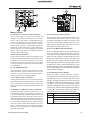
Driver Installation
7RXVHWKH+HOL[%RDUG)LUH:LUHPL[HUHI¿FLHQWO\RUDWDOORQD3&LWLVLPSRUWDQWWRLQVWDOODOOWKHQHFHVVDU\GULYers from the included CD (ASIO and WDM drivers). It is important that users read all instructions carefully before
continuing on to the each step of installation, as users will be required to unplug and plug in their FireWire device.
This is not necessary for Mac users.
Windows XP (with Service Pack 1 or 2)
1. It is recommended that you quit all applications before starting the installation process.
2. Ensure the Helix Board FireWire is not yet connected to your Computer’s FireWire input.
3. Insert the installation CD included with your Helix Board FireWire mixer into the CD-ROM drive of your computer.
If the CD does not automatically start the installation process within a few moments, then navigate to “My Computer” J your CD-ROM drive J “Drivers and Control Panel” J double-click “setup.exe” to begin the installation
manually. The Helix Board FireWire Control Panel software also will be installed at this time.
4. Follow the installation instructions.
Make sure no other programs are running on your PC and that the
Helix Board 24 FireWire MKII is not connected to your PC, then click “Next”.
16
Helix Board 24 FireWire MKII
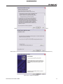
Read and accept the terms of the License Agreement and click “Yes” to continue.
Either select a new destination for the installation, or else click “Next” to accept the default directory.
Click “Next” to begin the installation.
Helix Board 24 FireWire MKII
17
Connect the Helix Board 24 FireWire MKII to the Computer and turn the power on.
If a message is displayed indicating that the software has not passed Windows Logo test,
click “Continue Anyway”.
After installation is complete, users are free to use the device as they wish.
18
Helix Board 24 FireWire MKII
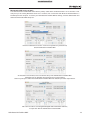
Macintosh OS X (10.3.5 or later)
The Helix Board 24 FireWire MKII works with the primary audio drivers of Macintosh OS X 10.3.5 and later. First
verify that you are running Macintosh OS X 10.3.5 or above, then connect the Helix Board 24 FireWire MKII to a
FireWire port to the computer. To ensure your Helix Board 24 FireWire MKII is working, enter the Utilities folder and
double-click the Audio MIDI Setup icon.
Enter the Audio Device’s section. From the “Properties for” pull-down tab,
select Helix Board 24 FireWire MKII.
At the bottom of the window, users can edit the setup of the Helix Board 24 FireWire MKII.
Properties such as sampling rate and clock source can be altered.
Users may also opt to make the Helix Board 24 FireWire MKII their default input and/or output device.
Mac users are able to use GarageBand Digital Audio Workstation Software,
in conjunction with the Helix Board 24 FireWire MKII.
Helix Board 24 FireWire MKII
19
Channel Assignment
Cubase LE
When using a Digital Audio Workstation on a PC, and
within the included Phonic Helix Board 24 FireWire
MKII control panel software, the following names have
been attributed to the input channels of the FireWire
mixer. They can be altered through the control panel
software included with the mixer.
Cubase LE is a fairly powerful program provided
along with the Helix Board 24 FireWire MKII mixer
that allows users to record, edit, delete, and alter their
tracks. Please note that only 4 tracks can be recorded
at once with the version of Cubase included, and usHUVPXVWXSJUDGHRU¿QGRWKHUVXLWDEOH'$:VRIWZDUH
if they choose to record more tracks.
FireWire Input Channel Name
Mixer Channel
Phonic HB 24 MKII CH 1
Channel 1
Phonic HB 24 MKII CH 2
Channel 2
Phonic HB 24 MKII CH 3
Channel 3
Phonic HB 24 MKII CH 4
Channel 4
Phonic HB 24 MKII CH 5
Channel 5
Phonic HB 24 MKII CH 6
Channel 6
Setup
Phonic HB 24 MKII CH 7
Channel 7
Phonic HB 24 MKII CH 8
Channel 8
Phonic HB 24 MKII CH 9
Channel 9
After successfully completing the installation process,
WKH IROORZLQJ SURFHVV PXVW EH IROORZHG WR ZRUN HI¿ciently with the Helix Board 24 FireWire MKII mixer.
Phonic HB 24 MKII CH 10
Channel 10
Phonic HB 24 MKII CH 11
Channel 11
Phonic HB 24 MKII CH 12
Channel 12
Phonic HB 24 MKII CH 13
Channel 13
Phonic HB 24 MKII CH 14
Channel 14
Phonic HB 24 MKII CH 15
Channel 15
Phonic HB 24 MKII CH 16
Channel 16
Phonic HB 24 MKII CH 17
Channel 17
Phonic HB 24 MKII CH 18
Channel 18
Phonic HB 24 MKII Main L
XVHUGH¿QDEOH
Phonic HB 24 MKII Main R
XVHUGH¿QDEOH
To alter an input channel’s name on your computer,
open the Helix Board 24 FireWire MKII control panel
software. On the left hand side of the control panel,
XVHUVZLOO¿QGWKHVHWWLQJVFDWHJRULHV%\FOLFNLQJ³,Qput Channels”, the main window will display the titles
input channels. You can then highlight the channel
names and press the “Edit Channel Name” button
on the bottom of the control window. A new window
will appear that will allow users to adjust the channel
name.
If you would like to use the Helix Board 24 FireWire
MKII as your default audio output device on you PC,
simply go into the Windows control panel, and select
“Sound and Audio Devices”. Select the Audio tab, and
use the pull-down menu to select the Helix Board 24
FireWire MKII from the list of available output devices.
The Helix Board 24 FireWire MKII can also be selected as the default output device for individual programs
by editing said programs’ settings / options.
20
Installation
Insert the Cubase LE installation CD that came with
your mixer into the CD drive of your computer. Run
the installer. The serial number will be automatically
entered in when installing.
1. Open the Cubase LE program.
2. Go to the ‘Devices’ pull-down menu and select ‘Device Setup’. On the left, select ‘VST Multitrack’.
3. From the ASIO Driver drop-down list select the
“Phonic ASIO Driver”. A pop-up box will ask you if
you want to switch the ASIO driver. Click ‘Switch’.
This completes the basic installation and setup.
4. Activating audio tracks received from the Helix
Board mixer.
a. Go to the “devices” pull-down menu and select
‘VST Inputs’. This will display the various inputs
(“Phonic HB 24 MKII Ch 1”, “Phonic HB 24 MKII
Ch 2”, etc.)
b. Activate 8 of these channels by clicking the
“Active” button located next to each channel
name. Please note, only 8 input channels can
be activated at any one time. This is a limitation
of Cubase LE, and if more input channels are
needed, we suggest upgrading to a higher version of Cubase, or use other DAW software.
5. For further instructions on the operation of Cubase,
please consult the user manual by pressing F1
while the program is open.
If you wish to reset the Helix Board 24 FireWire MKII
ASIO driver, simply go to the ‘devices’ pull-down menu
and select ‘device setup’. Simply click “reset” and select the “Phonic ASIO Driver”. Click ‘ok’ to continue
and the Helix Board 24 FireWire MKII should once
again become functional.
Helix Board 24 FireWire MKII
Helix Board Control Panel
The Helix Board FireWire control panel can be accessed at any time by entering choosing the shortcut
from your Programs menu. This program will not only
allow users to alter their device and channel names
and properties, but will also let them correct for latency issues, change sampling rates, and so forth.
When opening the software, a number of options will
be available for users to select from, allowing them to
adjust the available properties.
Output Channels
By entering the Output Channels section, users can
view and edit the names of the two output channels
from the computer to the Helix Board 24 FireWire MKII
mixer.
Devices
In the Devices section, users are able to view and edit
the name of the Phonic FireWire Devices connected
to their computer.
Synchronization
In the Synchronization section, users can adjust the
sampling rate and other synchronization properties.
Many of these adjustable properties, as they are, are
set for optimum performance and, unless you are sure
of what you need to change, are probably best left
alone.
Input Channels
The Input Channels section allows users to view and
edit the name of the various input channels received
from the FireWire input. For a list of default channel
names, please consult the table on page 18.
First off, the synch mode can be altered, though making this alteration is not recommended for novice users.
The synch mode is basically the way the computer determines what the ‘clock source’ (ie. device that your
computer will use to determine the timing of all digital
signals received) will be. The default setting for this
feature is “CSP”, meaning the Helix Board 24 FireWire
MKII is the “master” clock source of the device. The
other options allow users to make the Helix Board 24
FireWire MKII follow the “timing” of whichever device
is the clock source. Having two clock sources has
the potential to create very undesireable audio, so it
is best avoided. If the Helix Board 24 FireWire MKII
is the only piece of digital audio equipment attached
to the computer, there is no reason this option should
be changed.
Helix Board 24 FireWire MKII
21
Users are also able to change between automatic
and manual sampling rate settings. When the sampling rate is manually set, users can select between
sampling rates of 44.1, 48.0, 88.2 and 96.0 kHz per
second. Many devices have sampling rates that do
not surpass 44.1 kHz per second, therefore, when using multiple digital devices, users are advised not to
exceed this level unless they are sure the secondary
device’s sampling rate can .
Streams
In the Streams section, the Helix Board 24 FireWire
MKII device properties can be viewed. Each input
and output stream can be scrutinized, and the isochronous stream number and its supported sampling
rates can be viewed.
Settings
Users are able to adjust various buffer times in the
Settings section.
The Stream Buffer Depth is adjustable between 0.5
and 20 milliseconds. It adjusts the buffer used when
streaming a signal from the Helix Board 24 FireWire
MKII. If the depth is set too high, an obvious latency
will become evident. If the depth is too low, various
clicks and pops may become obvious. It is best to set
the Stream Buffer Depth to a level that allows users
to get the lowest latency, while still maintaining an optimal performance. The default settings are ideal for
most computers.
The ASIO Buffer Depth is adjustable between 4 and
40 milliseconds. This allows users to adjust the latency of the stream received by ASIO driver-based
software (including Steinberg Cubase LE).
The WDM (Windows Driver Model) Sound Buffer
Depth is adjustable between 4 and 40 milliseconds.
This allows users to adjust the latency of the stream
received by WDM based programs.
Also in this section, users are able to view their “drop
out statistics”, where the number of times the FireWire
connection has been interrupted can be viewed.
22
Helix Board 24 FireWire MKII
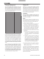
Troubleshooting
Driver Installation (Windows users only)
Software
ADS Pyro
64 FireWire card with a TI chip : :
:
8:47'1$:
'1 8:47 <: :
)7= # : 8:: : 8 97:>/
6<'1
<;
:7
/)7=#
8:47<::
:
887 %:7 " 16:: 5:<
/<;:7/7
Ricoh A 1< 2 <: . 9
7 ::888:
5:
/64
Texas Instruments’ /.##" <77 7>
<6 8 : ,4: 1< 2
.3 : < : . : :
577 ,4: 8 , 5
: :45<4:
'77<:::7:7:
7 577> *5 > : :
)7= # : : 8: 45 ::
:;:77:8:767>::
1<:::77:<;/
>;:4
;45:
# : 6 5 > ; . .
:77>;51</
;86:@=8:::
>5:)7=#:
Daisy-chaining
0 47 : : 47 : 4
5 8: 5 :> :< )7= #
7:7> / :< : 5
:>::)7=
# : : : : : )7=
# : : 8: 87> :
4:::
8::7>
.577>:::
8::?
4:)7=#
::::4:
;7 ; .
7 7
)7= # < 88 <: :7 *%
4 : > : 77< > :
: :< 577> *5 > 6 :
(0*% 4 88 : 4::
:
< > : : ;
: : 8: 5 > )7= # :> :7 > 47 : :: >
7::87
:4
3 8: 7 ? 4: )7=
# 77< > : 4: 4
8::
:77>
%>
::<)7=#
:::
:847
Helix Board 24 FireWire MKII
/ )7= # <: 5 8> 5
.:4$4+&47::6
7:7> / 6 577 5 :
)7= # ; : 8
.:4 : 97:> %"1
8
":> 5< 8
:: 77<
> : 7::6 : :
)7= # *: : :::; 8
8:77>;4::;7475
57: audacity.sourceforge.net
Phonic’s Online Support
*5 > 847
: 7; 5
> 5 :
8;5
:>:::
786:www.phonic.com/support
#5 :: 5 > 78 87
6:577<:
67;>
847
:
1. $6 :: : '1 47 @
7>
: : 4: : )7= # 8:
2. 0:77 : '1 ; 5
>
8::>
3. 0:77:)7=4;:77:
7::;>::::>77>
: :77: 8
5
5:
<6578
4. $65:)7=#:787<
77 ; 8: :8: 7
:7>
5. /> : '1 @= :: 8: <4:51<2<:.
* : 87 55 : 577<
5
::78:
:847
1. -8:.>:
!1<-.<:.
.:,-.2;!
2. 1: %"1 5:< 5:<
>:>:!
3. % > :77 > : '1 ;
;45!14
7!
4. 1: : 4 '1 :5
>!
5. "> :7 5
: > 8;
::>:6
>78
23
Digital Effects Table
NO
PARAMETER SETTING
ROOM
EARLY LEVEL
NO
PARAMETER SETTING
PAN
PROGRAM NAME
SPEED
TYPE
00
COMPACT ROOM 1
0.05
100
56
SLOW PAN
0.1
R-->L
01
COMPACT ROOM 2
0.4
0
57
SLOW PAN 1
0.1
R<-->L
02
SMALL ROOM 1
0.45
100
58
SLOW PAN 2
0.4
R-->L
03
SMALL ROOM 2
0.6
90
59
MID SHIFT
0.8
R<-->L
04
MID ROOM 1
0.9
100
60
MID SHIFT 1
1.2
L-->R
05
MID ROOM 2
1
50
61
MID SHIFT 2
1.8
L-->R
06
BIG ROOM 1
1.2
100
62
MID SHIFT 3
1.8
R-->L
07
TUNNEL
63
FAST MOVE
HALL
3.85
100
REV-TIME
EARLY LEVEL
TREMOLO
3.4
R<-->L
SPEED
MODE-TYPE
TRG
08
JAZZ CLUB
0.9
90
64
LAZY TREMOLO
0.8
09
SMALL HALL 1
1.5
72
65
VINTAGE TREMOLO
1.5
TRG
10
SMALL HALL 2
1.75
85
66
WARM TREMOLO
2.8
TRG
11
SPRING HALL
1.9
98
67
WARM TREMOLO 1
4.6
TRG
12
MID HALL 1
2.3
100
68
HOT TREMOLO
6.8
TRG
13
MID HALL 2
2.45
80
69
HOT TREMOLO 1
9.6
TRG
14
RECITAL HALL
2.7
96
70
CRAZY TREMOLO 1
15
TRG
15
BIG HALL 2
3.3
88
71
CRAZY TREMOLO 2
20
TRG
REV-TIME
HPF
REV
DELAY
PLATE
DELAY+REV
16
SMALL PLATE
0.9
0
72
DELAY+REV 1
1
1
17
TAIL PLATE
1.2
20
73
DELAY+REV 2
2
2
18
MID PLATE 1
1.3
0
74
DELAY+REV 3
3
3
19
MID PLATE 2
2.2
0
75
DELAY+REV 4
4
4
20
REVERSE PLATE
2.25
42
76
DELAY+REV 5
5
5
21
LONG PLATE 1
2.6
80
77
DELAY+REV 6
6
6
22
LONG PLATE 2
3
625
78
DELAY+REV 7
7
7
23
LONG PLATE 3
4.2
0
79
DELAY+REV 8
8
8
DELAY AVERG.
R-BEVEL
CHORUS+REV
REV
CHORUS
DELAY (STEREO)
24
SHORT DELAY 1
0.07
60
80
CHORUS+REV 1
1
1
25
SHORT DELAY 2
0.14
60
81
CHORUS+REV 2
2
2
26
PING PONG DELAY
0.11
55
82
CHORUS+REV 3
3
3
27
MID DELAY 1
0.15
55
83
CHORUS+REV 4
4
4
28
MID DELAY 2
0.3
60
84
CHORUS+REV 5
5
5
29
SHORT DELAY 1(MONO)
0.06
100
85
CHORUS+REV 6
6
6
30
MID DELAY 1 (MONO)
0.13
100
86
CHORUS+REV 7
7
7
31
LONG DELAY 1(MONO)
0.18
100
87
CHORUS+REV 8
8
8
CHORUS
LFO
DEPTH
FLANGER+REV
REV
FLANGER
32
SOFT CHORUS
0.2
56
88
FLANGER+REV 1
1
1
33
SOFT CHORUS 2
0.5
70
89
FLANGER+REV 2
2
2
34
SOFT CHORUS 3
0.8
75
90
FLANGER+REV 3
3
3
35
WARM CHORUS
1.8
85
91
FLANGER+REV 4
4
4
36
WARM CHORUS 1
3.2
80
92
FLANGER+REV 5
5
5
37
WARM CHORUS 2
5.2
45
93
FLANGER+REV 6
6
6
38
WARM CHORUS 3
7.8
52
94
FLANGER+REV 7
7
7
39
HEAVY CHORUS
9.6
48
95
FLANGER+REV 8
8
8
LFO
DEPTH
RELEASE
REV
FLANGER
GATED-REV
40
CLASSIC FLANGER 1
0.1
44
96
GATED-REV-1 9
41
CLASSIC FLANGER 2
0.3
63
97
GATED-REV-2 10
42
GENTLE FLANGER
0.6
45
98
GATED-REV-1 9
43
WARM FLANGER
1.6
60
99
GATED-REV-2 10
44
MODERN FLANGER 1
2
85
45
MODERN FLANGER 2
2.8
80
46
DEEP FALANGER 1
4.6
47
DEEP FALANGER 2
10
PHASER
24
PROGRAM NAME
REV-TIME
0.02
TAIL PLATE
0.2
TAIL PLATE
0.02
REVERSE PLATE
0.5
REVERSE PLATE
TAP DELAY
FB LEVEL
RANGE
A0
TAP DELAY
0
100mS - 2.7S
75
A1
TAP DELAY
10
100mS - 2.7S
60
A2
TAP DELAY
20
100mS - 2.7S
LFO
DEPTH
A3
TAP DELAY
30
100mS - 2.7S
48
CLASSIC PHASER 1
0.1
3.6
A4
TAP DELAY
40
100mS - 2.7S
49
CLASSIC PHASER 2
0.4
2.6
A5
TAP DELAY
50
100mS - 2.7S
50
COOL PHASER
1.4
0.7
A6
TAP DELAY
60
100mS - 2.7S
51
WARM PHASER
3.2
0.3
A7
TAP DELAY
70
100mS - 2.7S
52
HEAVY PHASER 1
5
1.2
A8
TAP DELAY
80
100mS - 2.7S
53
HEAVY PHASER 2
6
2.8
TEST TONE
FREQUENCY
SHAPE
54
WILD PHASER 1
7.4
0.8
T0
LOW FREQUENCY
100Hz
SINEWAVE
55
WILD PHASER 2
9.6
4.8
T1
MID FREQUENCY
T2
HIGH FREQUENCY
PN
PINK NOISE
1kHz
SINEWAVE
10kHz
SINEWAVE
20Hz~20kHz
Helix Board 24 FireWire MKII
Application
Live Band Multi-Track Recording and Monitoring
Helix Board 24 FireWire MKII
25
Studio Recording and Monitoring
26
Helix Board 24 FireWire MKII
6SHFL¿FDWLRQV
Helix Board 24 FireWire MKII
Inputs
Balanced Mic / Line channel
Aux Return
2T Input
16
4 stereo
Stereo RCA
Outputs
Main L/R Stereo
Main out with inserts
Main Mono
Main Mono out with inserts
2 x 1/4” TRS, Bal. & 2 x XLR
Yes
1 x 1/4” TRS, Bal. & 1 x XLR
Yes
Subgroup outputs
4x 1/4” TRS, Bal.
Aux sends
6x 1/4” TRS, Bal.
DSP effect outputs
2 x 1/4” TS
CTRL RM L/R
2 x 1/4” TS
Phones
SPDIF digital output
Firewire Interface
Channel Strips
Aux Sends
1
44.1kHz
18 out & 2 in, 24-bit / 96 kHz, 2 FireWire ports
16
6 with 4 volume control
Pan/Balance Control
Yes
Channel On/Mute
Yes
Channel solo with metering
Yes
LED indicators
On, Signal, Peak/Solo
Bus assign switches
1/2, 3/4, L/R
Volume Controls
60mm fader
Master Section
FireWire channel 17/18 rounting switch
Source from main mix, group 1/2, and aux 3/4
Aux Send Masters
4
Master Aux Send Solo
4
Stereo Aux Returns
4
Aux Return Assign to Subgroup
1
Effects Return to Monitor
Global PRE/POST Solo Mode
Faders
3
Yes
4 subgroups, Main L/R
Metering
Number of Channels
2
Segments
12
Phantom Power Supply
Switches
Effect Processor (40-bit DSP)
+48V DC
Master switch
+LJKGH¿QLWLRQDOJRULWKPSURJUDPVSOXVWDSGHOD\
foot switch (effect on/off, tap)
Frequency Response (Mic input to any output)
20Hz ~ 60KHz
+0/-1 dB
20Hz ~ 100KHz
+0/-3 dB
Helix Board 24 FireWire MKII
27
Crosstalk (1KHz @ 0dBu, 20Hz to 20KHz bandwidth, channel in to main L/R outputs)
Channel fader down, other channels at unity
<-90 dB
1RLVH+]a.+]PHDVXUHGDWPDLQRXWSXW&KDQQHOVXQLWJDLQ(4ÀDWDOOFKDQQHOVRQPDLQPL[
channels 1/3 as far left as possible, channels 2/4 as far right as possible. Reference=+6dBu)
Master @ unity, channel fader down
-86.5 dBu
Master @ unity, channel fader @ unity
-84 dBu
S/N ratio, ref to +4
>90 dB
Microphone Preamp E.I.N. (150
max gain)
ohms terminated,
THD (Any output, 1KHz @ +14dBu, 20Hz to 20KHz,
channel inputs)
CMRR (1 KHz @ -60dBu, Gain at maximum)
<-129.5 dBm
<0.005%
80dB
Maximum Level
Mic Preamp Input
+10dBu
All Other Inputs (except inserts)
+22dBu
Balanced Outputs
+28dBu
All other outputs
+22dBu
Impedance
Mic Preamp Input
2 K ohms
All Other Input (except insert)
10 K ohms
RCA 2T Output
1.1 K ohms
All other outputs
Equalization
100 ohms
3-band, +/-15dB
Low EQ
80Hz
Mid EQ
100-8k Hz, sweepable
Hi EQ
/RZFXW¿OWHU
12 kHz
75 Hz (-18 dB/oct)
Power and Physical Attributes
Built-in Switching Power Supply
Net Weight
Dimensions (WxHxD)
28
100-240 VAC, 50/60 Hz
10.5 kg (23.1 lbs)
445 x 212 x 432 mm (17.5” x 8.3” x 17”)
Helix Board 24 FireWire MKII
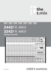
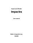
Dimensions
0
0
0
0
0
* All measurements are shown in mm/inches.
Helix Board 24 FireWire MKII
29
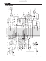
R
L(MONO)
DSP EFFECT OUT
CH1~8 ONLY
DIRECT OUT
INSERT
LINE IN
CHANNEL 1~16
1
2
3
MIC IN
R
AUX RTN4
L(MONO)
R
L
R
AUX RTN2
L(MONO)
R
L(MONO)
AUX RTN1
PRE/POST
75Hz
HPF
GAIN
PEAK
TAP DELAY
EFFECT ON/OFF
100-EFX
AUX RTN3
SIG
AUX 2
AUX 1
ON
SIG
R TN4
R TN3
RTN2
SOLO
AUX SEND3 TO EFX
4
3
2
1
R
L
TO AUX2
TO AUX1
3/4
1/2
MAIN/GP
SOLO
SHIFT 5/6
PAN
C-R/PHNS ONLY
TO AUX1
RTN1
FADER
PROGRAM(PUSH SEL.)
BYPASS
AUX 4
AUX3/EFX
PRE/
POST
MID FREQ
80
8K 100
12K
CH1~16 TO FIREWIRE
LOW CUT
LO
MID
EQ
HI
PEAK(SOLO)
POST MIX
PRE MIX
GRN
RED
TRIM
1
3
5
PRE/POST
MAIN/GP1-2/
AUX3-4
MAIN INS R
SOLO RELAY
RIGHT
LEFT
TO L/R
TO AUX1
GP2 TO FIREWIRE
AUX4 TO FIREWIRE
GP1 TO FIREWIRE
AUX3 TO FIREWIRE
CH1~16 TO FIREWIRE
MAIN MIX
MAIN INS L
SOLO
AUX SEND
FIREWIRE MOD.
1
3
5
FIREWIRE
2
4
6
1394Firewire Jack
MAIN
AUX4/L-R
2
4
6
SOURCE
S/PDIF OUT
1
1
MAIN L-R
SOURCE MIX
GP2_4
60~160Hz
2T RTN
MAIN R
PEAK
+10
+7
+4
+2
0
-2
-4
-7
-10
-20
-30
3
MONO/SUBWOOFER
2
+12V LAMP
BNC JACK
CTRL RM R
PHONES
CTRL RM L
GROUPS OUT
2T RTN R
2T RTN L
0dBu=0.775V
PHONES
CTRL RM/
+12V
LEVEL
REC OUT L
REC OUT R
ON/OFF
MAIN L
LPF
MONO INS
FROM GP1_3
2T TO MAIN
2T RTN
GP1-2/3-4
FIREWIRE
MONO MIX
AUX SEND5/6
(ONLY AUX4 FOR MONO)
AUX SEND1~4
AUX SEND3 TO EFX
2
3
2
30
3
MAIN R
MAIN L
1
+48V
Block Diagram
SOLO C
PFL R
PFL L
AFL R
AFL L
AUX6
AUX5
AUX4
AUX3
AUX2
AUX1
GP4
GP3
GP2
GP1
Helix Board 24 FireWire MKII
6103 Johns Road #7