1
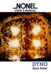
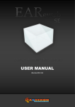
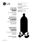
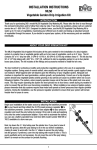
Blast PED ST
®
Owner Manual
Sydney:
Mine Site Technologies Pty Limited
PO Box 156
Artarmon NSW 1570
Australia
Tel:
02-9437 4399
Fax:
02-9437 5688
Email: [email protected]
Web: www.minesite.com.au
Mt Isa:
Mine Site Technologies Pty Limited
PO Box 2436
Mt Isa QLD 4825
Australia
Tel:
07-4749 4922
Fax:
07-4749 4933
Email: [email protected]
Kalgoorlie:
Mine Site Technologies Pty Limited
PO Box 4200
Kalgoorlie WA 6430
Australia
Tel:
08-9022 2300
Fax:
08-9022 2311
Email: [email protected]
BlastPED® ST
Owner Manual
CONTENTS
1.
OVERVIEW
2.
SPECIFICATION
3
3.
SAFETY
3.1
Access Restriction
3.2
Addressing
3.3
Remote Initiator Hardware
5
5
5
5
4.
SYSTEM OPERATION
4.1
Remote
4.2
Controller
4.3
System with Two Remotes
4.4
Use with a Repeater
7
7
7
8
8
5.
SECURITY
5.1
Unit Number
5.2
PIN Number
5.3
Number Change Process
10
10
10
10
6.
SYSTEM EXCHANGE
6.1
Service Return
11
11
7.
ON SITE
7.1
Testing
7.2
Carriage on Site
7.3
Site Set Up
7.4
What to Do, IF?
11
11
13
14
14
8.
CARE
8.1
Battery Charging
8.2
Service and Battery Changing
8.3
Storage
15
15
15
15
9.
OPERATION SCHEMATIC
16
\\Syd2\manuals\BlastPED\BlastPED ST\Owners Doc Rev 7_A.2.doc
Page 3
Page 2 of 17
1.
OVERVIEW
The BlastPED ST System (also known as BlastPED EXEL) has been developed
for use in open cut mines to provide an alternative to safety fuse and cablebased firing systems.
The System consists of a Controller and either one or two Remote initiators
(see Operation Schematic in Section 9).
The BlastPED ST System allows remote blasting using a radio-based link
between shot firer and blast site. The difference between BlastPED ST and
other versions of BlastPED is that Remote/s are used to directly initiate signal
tube rather than initiate electric detonators.
BlastPED ST has been designed with safety as the main criteria. The
system has several levels of security, but authorised personnel will find it
straight forward and simple to operate.
2.
SPECIFICATION
Each BlastPED ST System comprises:
•
•
•
Controller
One or two Remotes (radio operated signal tube Initiators)
Battery charger for each Controller and Remote.
Both Controller and Remotes are portable and battery powered. The two-way
radio link between the Controller and the Remote is automatically maintained
by the BlastPED ST System through Spread Spectrum radio transceivers
internal to the units. The Controller and Remote transceivers are operating at
a power output of up to 1 Watt in the band of 900 MHz, and do not require
licensing. Maximum operating distance between the Controller and a Remote
depends on local terrain and extends to 4 kilometers under Line-of-Sight
conditions.
Construction of the system is suited to purpose with both the Remote and
Controller being rugged in design.
The Remote is designed to withstand high pressure as imposed by blast
concussion and is water resistant, chemical resistant and able to withstand
general neglect.
\\Syd2\manuals\BlastPED\BlastPED ST\Owners Doc Rev 7_A.2.doc
Page 3 of 17
Nylon 6/6 conditioned tubing is machined to form the main body and battery
housing, whilst in later manufacture polyethelyne one piece mouldings are
used for the main body. Delrin (Acetal Sheet) is machined from solid to form
the Battery Cap, and the Bulkhead for the Nylon bodied units. The Face is
machined from clear Acrylic sheet, which was chosen for clarity, strength and
scratch resistance. All have very high tensile strength and resistance to a
large range of chemicals, whilst their dielectric and surface resistivity
capabilities are suited to purpose.
Neoprene rubber "O" ring seals are fitted to the Battery Cap, Bulkhead, Face
and Battery contacts so as to ensure compliance with IP66. All face fittings
are to IP66 and are gasketed and sealed accordingly.
The Controller utilises a proprietary housing in the form of a "Pelican" #1450
water resistant suitcase style enclosure built to IP 67 standard. The controller
face fittings comply with IP65. Materials used in the construction of the
Controller housing are polypropylene whilst the face membrane is
polyurethane, both of which offer excellent chemical and wear resistance. A
neoprene rubber “O” ring is used to seal the face to the housing.
Housing
Material
Size
Operating Temp
Range
Weight
Battery
Battery Charger
Access
controlled by
Controller
Rated IP 65
Polypropylene
410mm L x 336mm W x
178mm H
0oC to +70oC
Remote Initiator
Rated IP 66
Nylon 6/6 or Polyethylene
4.2 kg (Inc Battery)
Type: NiMH 12V, 2700mAh
Not removable by user
4.5 kg (Inc Battery)
Type: NiMH 12V,
2700mAh
Removable
240V-12V DC
Key and Controller
240V-12V DC
Key and PIN
Spark Plug
\\Syd2\manuals\BlastPED\BlastPED ST\Owners Doc Rev 7_A.2.doc
N:141mm Dia x 497mm H
P:180 mm Dia x 500 mm H
0oC to +70oC
3mm Standard Tube
Optional : 4mm
Page 4 of 17
3.
SAFETY
The System has numerous levels of both “Hard” and “Soft” security, as
outlined below.
3.1
Access Restriction
Access to the Controller is restricted by a safety switch key (common to
all BlastPED ST units) and a four digit “PIN” entered via the keyboard.
Access to the Remote is restricted by a safety key and Controller “PIN”
There are two PINs
•
•
Owner PIN
User PIN
The PIN numbers are programmed into the Controller on two levels of
privilege as outlined below:
Level
Privilege
Owner PIN Operate both remote units.
Allows change of User PIN.
Operates both Remote units.
User PIN
3.2
Addressing Using System Numbers
Each BlastPED ST System has the following five (5) System Numbers
assigned and controlled by MST:
•
•
•
•
•
3.3
Radio Network Number.
Radio Local Address for Remote Modem No. 1.
Radio Local Address for Remote Modem No. 2.
ID of Remote Initiator No. 1
ID of Remote Initiator No. 2.
Remote Initiator Hardware
Signal tube is initiated by a spark plug mounted on the face of the
Remote unit.
12 V input to the High Voltage Converter is the source of energy
needed to make a spark.
\\Syd2\manuals\BlastPED\BlastPED ST\Owners Doc Rev 7_A.2.doc
Page 5 of 17
During blasting the firing capacitor is charged by the Converter, and
when 3000V is reached a secondary spark gap is breached between
the firing capacitor and the spark plug.
This increases the critical voltage on the capacitor to 5200 V and thus
prevents inadvertent spark by any remnant charge on the capacitor.
Bleeding resistors are placed across the firing capacitor to remove
remnant charge and prevent charge build up.
High Voltage Converter Control Entities
No.
1
Hardware
Timer 1
2
Timer 2
3
Timer 3
4
Counter
5
Comparator
6
Latch
7
Microprocessor
Function
Disables blasting for a selected time period
following turning the Remote Safety Switch ON.
Disables blasting after a selected time period
following turning the Remote Safety Switch ON.
Disables blasting but for the time period during
arming.
Controls levels of security negotiated in the
process.
Normally reset to zero.
Incremented to 2 when arming.
Incremented to 6 when blasting.
Validates the process of going through subsequent
levels of security.
Locks out the Remote if breach of security
detected.
Receives, validates and executes commands from
the Controller.
Notes:
♦ Timers 1and 2 are set by manually changing jumpers on the Remote
PCB.
♦ Arming (and subsequent Blasting) is enabled only in the “Blasting
Window”, that is from time as set on Timer 1, to time as set on Timer 2
(from turning the Remote Safety Key ON).
♦ Blasting is enabled only in the “Firing Window”, that is for time as set
on Timer 3 (15 seconds) after Arming.
Timer settings & Pin Numbers for a particular system are printed on a label
which can be found in the lid of the Controller unit.
\\Syd2\manuals\BlastPED\BlastPED ST\Owners Doc Rev 7_A.2.doc
Page 6 of 17
4.
SYSTEM OPERATION
4.1
Remote
Use the Remote as per the instructions printed on the body, and as
indicated below.
OPERATING INSTRUCTIONS
Note: Tests should be completed in the workshop before each blast to
confirm Battery and Communication Status.
1. Shotfirer to remove key from BlastPED Controller before setting up
BlastPED Remote.
2. Check BlastPED Remote key is in SAFE position.
Note: When inserting the key, ensure the small lug on the rubber
key handle cover, points towards the ‘SAFE’ position.
3. When setting up ensure that the Remote is in a location such as to
prevent damage from the blast and is also in Line-of-Sight of the
proposed Controller location.
4. Switch on Remote.
5. Check that “ON” LED is illuminated.
6. Thread Signal tube through handle.
7. Insert Signal Tube into sparker. Make sure that tube is fully inserted
and secured against any wind. Fit Rain Cap if necessary.
8. Proceed to proposed Controller location and set up by following
instructions on Controller (see following Section 4.2).
AFTER BLAST
9. Turn BlastPED Controller Key to SAFE after blast
10.Turn BlastPED Remote Key to SAFE after blast.
4.2
Controller
Use the Controller as per the instructions printed on the face, and as
indicated on following page (8).
\\Syd2\manuals\BlastPED\BlastPED ST\Owners Doc Rev 7_A.2.doc
Page 7 of 17
OPERATING INSTRUCTIONS
1. Raise Antenna (Check that antenna is "firm" in housing. Adjust if
necessary)
2. Turn ON
3. Enter “PIN"
Enter #
Optional: Enter REPEATER number (3 or 4)
Enter Remote number
ERROR light ON.
WAIT light ON.
4. ARM.
When READY light ON
5. BLAST.
When ARMED light ON
(within 15 seconds of ARM)
Completed Cycle
Return Controller and Remote to
SAFE before commencing another
cycle.
BLASTED light ON.
SAFE light ON.
4.3
Return to SAFE
Wait
Systems with Two (2) Remote Initiators
Only one unit can be used at a time. Remote 1 has to have BLASTED
and returned to SAFE after which the complete Controller Instructions
are again followed.
NOTE: Select Remote 2 after entering PIN or the unit will not work
4.4
Systems requiring a REPEATER (Optional)
A Repeater is used when an obstruction, or distance interferes with
direct communication between Controller and Remote.Set the
Repeater at the selected position making sure that both Remote and
Controller are in "Line of Sight" of the Repeater. Follow instructions
listed on front panel of the Repeater, and make sure that the unit is
switched ON before leaving the site. (Fig 1)
NOTE: Be sure connect 2 x antennas as supplied on the Repeater, or
separate antenna system.
\\Syd2\manuals\BlastPED\BlastPED ST\Owners Doc Rev 7_A.2.doc
Page 8 of 17
Fig 1.
The Repeater provides a “Transparent” link between Controller and Remote
via two radios, that, whilst hard wired, will only talk to their allotted partner.
The Controller talks to the Slave and the Master talks to the Remote. The
Repeater is passive unless a network link is established with the BlastPED
Controller. As soon as the Repeater is dialled by the Controller, it powers the
Repeater Master Radio which links to the Remote. When the Controller goes
off the network the link is broken and the Repeater Master Radio is shut
down.
Thus the Controller can dial up any Remote either directly or through
Repeater No.3 or through Repeater No. 4.
All four devices: (two Remotes and two Repeaters) can be switched on all the
time, but networks and links will be established by the Controller on demand
only.
PIN number sequences are as follows:
PIN#1 to dial direct to Remote 1
PIN#2 to dial direct to Remote 2
PIN#31 to dial Remote 1 through Repeater 3
PIN#41 to dial Remote 1 through Repeater 4
PIN#32 to dial Remote 2 through Repeater 3
PIN#42 to dial Remote 2 through Repeater 4
\\Syd2\manuals\BlastPED\BlastPED ST\Owners Doc Rev 7_A.2.doc
Page 9 of 17
5. SECURITY
5.1
Unit Number
Relates to the System number, which is attached on a decal affixed to
the face of the Controller, and on the decal on the lid of the Controller.
The Remote system number includes the Unit number shown as 1.1,
and where two Remotes constitute a system the numbers will be
shown as 1.1 and 1.2. These numbers are engraved on a plaque
affixed to the left lower face of each Remote.
5.2
PIN Number
PIN numbers are used to ensure SECURITY of USE and are protected
and changed in the same way as a credit card PIN. The user has an
allocated number.
The Owner has a selectable number. The Distributor has a selectable
number as for the Owner.
The User is unable to program a new number
The Owner is able to program a new user number
5.3
Number Entry and Change Process
Step
1
2
3
4
5
6
(Owner)
Action
Enter Owner PIN
Enter # #
Enter new User PIN
Enter #
Re Enter new User PIN.
Enter #
(Both Remote indicator lights will blink signifying
acceptance of New PIN number.)
\\Syd2\manuals\BlastPED\BlastPED ST\Owners Doc Rev 7_A.2.doc
Page 10 of 17
6. SYSTEM EXCHANGE
MST policy is: “All BlastPED units manufactured by MST are Not User
Serviceable”
BlastPED ST is no exception. Indeed, it is most important that no party,
other than MST service personnel, or accredited service
representatives repair the system. Since safety and reliability of the
product has been the subject of exhaustive Risk Analysis by MST, we
require that the process maintain integrity by disallowing interference
by any other party.
To achieve compliance with the policy an exchange program is
available to the user.
6.1
Service Return
When the Owner or Distributor returns a system to MST for service,
they must advise where it came from and which system number
replaced it, so as to obtain the allocated Owner PIN for the
replacement system.
7. ON SITE
The BlastPED ST System is an instrument and should be treated as such.
Arrangements should be made to store the system in an appropriate place
when not in use and when on charge.
A secure clean dry storage area is best where charging can take place
without interference from other activities. Only authorised trained personnel
should have access to the equipment so as to ensure its correct charging
procedure and that it is clean and ready or use.
7.1
Testing
Two tests are available to the user before use, being:
• Test sequence (1) indicated on the Controller
• A full functional test (2) as per the operating instructions also
indicated on the Controller.
\\Syd2\manuals\BlastPED\BlastPED ST\Owners Doc Rev 7_A.2.doc
Page 11 of 17
NOTE 1:
Before beginning either test place the controller at least
five metres from the Remote and in Line-of-Site of each
other.
NOTE 2:
Mine Site Technologies recommends that the BlastPED
ST be serviced every 12 months, or after 1000 shots.
.
1.
Condition Test
1.
2.
3.
4.
Turn on the Remote
Turn on the Controller
Enter User, or Owner PIN # and Remote number
Wait until all three (3) test lights on the Controller flash,
and then Press TEST
Three blue lights will light-up indicating
♦ Controller Battery Condition OK
♦ Communication OK
♦ Remote Battery Condition OK
2.
Functional Test
Follow Operating Instructions
The System can be fired without Signal Tube but should a short
piece (100mm) be required, install as per manufacturer’s
instructions.
SAFETY GLASSES MUST BE WORN during test 2. And no personnel
should be in the immediate vicinity.
3.
Self-Test (Integrity Test)
BlastPED ST Self-Test checks the internal Remote electronics. In
particular it tests the state of the Remote unit’s protective circuitry upon
which safety relies.
The test may take up to 2.5 hours to complete, depending upon the
setting of the internal timers of the Remote Unit.
To test the integrity of the BlastPED ST Remote unit internal
electronics, perform the following:
1. Connect both the BlastPED ST Remote and BlastPED ST
Controller to their respective chargers. (Position the Remote unit
and the Controller at least 2 to 3 meters apart, otherwise the RF
stages of the radios can be overloaded and cause signal distortion)
\\Syd2\manuals\BlastPED\BlastPED ST\Owners Doc Rev 7_A.2.doc
Page 12 of 17
2. Connect the Chargers together using the supplied cable.
Supplied Cable
3.
Put power on to both Chargers.
4.
Switch on the Remote Unit.
5.
When switching on the Controller, either hold button “1” (for
Remote 1) or button “2” (for Remote 2) pressed while turning the
power key switch. That is, holding “1” or “2” performs test to
Remote unit “1” or “2” respectively.
6.
The “Test in progress” is indicated by the three blue TEST LED’s
flashing in sequence. (Controller Battery OK LED,
Communication OK LED, and the BlastPED Battery OK LED)
7.
On the Controller, while the three blue TEST LED’s are flashing,
the “Remote State” LED’s indicate the progress of the Test
sequence. They will change from WAIT to READY to ARMED to
READY to ARMED and finally SAFE. If the test completes
correctly, the three blue TEST LED’s will be on steady with the
SAFE LED.
If the Test Sequence fails, the ERROR LED will flash with a certain pattern
(number of quick flashes), followed by a short pause (about 2 seconds). The
number of flashes gives an indication of the reason for the test failure. Please
contact Mine Site Technologies for assistance.
NOTE: The Integrity Test is an independent test and does not co-exist with charging.
The use of the chargers (and associated interconnecting lead) is merely to enable the
Integrity test to be performed.
To properly charge the units (controller and remote), the units must be in the SAFE
mode (off). If after performing the integrity test and wishing to ensure the batteries
are fully charged:
1. Return units to safe -
\\Syd2\manuals\BlastPED\BlastPED ST\Owners Doc Rev 7_A.2.doc
Page 13 of 17
2. Disconnect from charger 3. Re-connect to charger -
7.2
Carriage on Site
Transport of the system to site should be done with care that would
normally be attributed to an instrument. The Remote/Remotes should
be restrained so as not to roll around and the Controller also. Since the
units are to be protected from rain etc they will most probably be
carried within a vehicle and preferably on the floor. However, should
the User/Owner wish to carry the units in the back of a ute retainers
such as fire extinguisher brackets can be used for the Remotes and an
occy strap for the Controller.
7.3
Site Setup
The selected site for setting up the Remote/Remotes should take into
account the following:
♦
♦
♦
♦
♦
♦
♦
♦
♦
♦
♦
♦
♦
Suitable distance from blast.
Effect of blast on Remote – Air Blast – Flyrock etc
Flat level surface for the Remote to stand.
Line-of-Sight from proposed Controller firing site.
Remote Antenna should not be obstructed by the handle, from Lineof-Sight of the Controller antenna.
Follow the instructions on the Remote.
DO NOT FIT SIGNAL TUBE UNTIL THE REMOTE IS SWITCHED
ON.
Exit the site with care and proceed to Controller site.
Controller site should be selected so as to provide Line-of-Sight of
Remote when firing.
Care should be taken with selection of site so as to prevent
accidents occurring due to the terrain.
Follow the instructions printed on the face of the Controller.
When the blast is completed and the Controller indicates BLASTED
and SAFE the Remote should be retrieved and inspected for
damage.
Return all units to storage and place on charge.
\\Syd2\manuals\BlastPED\BlastPED ST\Owners Doc Rev 7_A.2.doc
Page 14 of 17
7.4
What to Do “IF”
MISFIRE.
If BLASTED and SAFE ON, Check Spark Plug.
If READY on, Retry ARM and BLAST.
ERROR on.
Incorrect Input
COMMS FAIL on.
Remote battery flat.
Remote not switched ON.
Switch to SAFE and back ON. Retry.
Not in Line-of-Sight.
Other Interference.
Switch to SAFE and back ON.
Retry.
If continued failure, Return to
store.
COMMS FAIL light blinking intermittently means that communication
may be weak, but not ineffective. Information will still be relayed
between the Remote and Controller.
The “Blasting Window” time span preset by MST to suit the Mines
procedures, and pre set between T1 and T2 will be sufficient to allow
the User to switch Controller to SAFE and back ON, and try again.
Should the “Window” expire the Remote will have to be reset and the
sequence re started.
8.
CARE
Whilst the System units are robust and designed with harsh conditions in mind
care should be taken not treat them in an irresponsible manner.
Keep them clean and free from any toxic substance by wiping over with a
moist cloth wetted with water and a light detergent.
8.1
Battery Charging
Make sure the Remote and Controller units are switched to SAFE. Plug
the respective charging leads into the units, making sure that the
receptacles are free from moisture and foreign particles. Do not force.
Make sure the keyways are aligned.
Put power on to the chargers
\\Syd2\manuals\BlastPED\BlastPED ST\Owners Doc Rev 7_A.2.doc
Page 15 of 17
The charge light will glow continuously until such time the battery is
charged after which, the ready light will glow.
Should the charger be left on continuously the On light will glow and
the Ready light will pulse until the charge plug is inserted into the unit,
at which time the Charging light will glow.
8.2
Servicing and Battery Changing
The System and batteries are not User Serviceable
8.3
Storage
The System can be stored indefinitely. Make sure that all units are switched to
SAFE and they are housed in a clean dry place. Care should be taken that no
remnants of toxic chemicals remain on the housings. Before reusing units they
should be fully charged and tested as described in Section 7.1
\\Syd2\manuals\BlastPED\BlastPED ST\Owners Doc Rev 7_A.2.doc
Page 16 of 17
\\Syd2\manuals\BlastPED\BlastPED ST\Owners Doc Rev 7_A.2.doc
Page 17 of 17
The unit is battery powered and
fully self contained.
Displays Remote Receiver status
at all stages of the blasting cycle.
A Key & a PIN Code give access
to send secure, specially coded
ARM & BLAST commands to the
Remote Receiver.
Controller
Signaling is two-way, Controller
to Remote and Remote to
Controller.
Spread Spectrum radios are used
for safety, and are license free.
Two-way Radio Signals
The unit is battery powered and fully self
contained, and provides feed back on its
status to the Controller.
Receives and executes commands sent
from the Controller unit. On receipt of
valid
BLAST
command,
internal
capacitors are fast charged, then
discharged into the signal tube spark
plug. The signal tube/shock tube then
initiates the blast as normal.
Remote Receiver Initiator
9. BlastPED ST – Operation Schematic