1
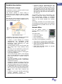
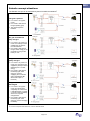
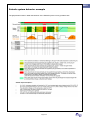
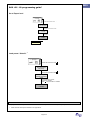
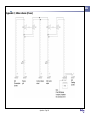
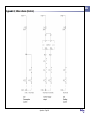
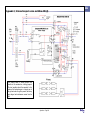
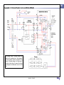
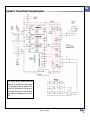
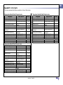
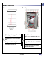
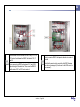
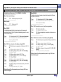
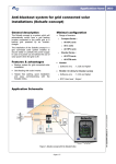
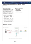
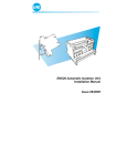
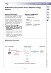
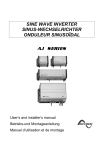
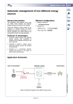
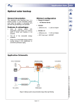
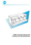
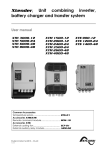
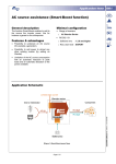
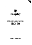
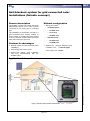
Application Note 003
Anti-blackout system for grid connected solar
installations (Solsafe concept)
General description
The Solsafe concept is a system which will
automatically switch from a solar inverter
connected to the public grid to a backup
grid.
Minimal configuration
• Range of inverters
o
Compact Series :
o All XPC serie
The installation of the Solsafe concept in a
grid connected solar system enables to
secure totally or partially the power supply
in case of a power cut and allows the use of
solar power when the grid is off.
o All C serie
o All HPC serie
o
Xtender Series :
o All XTH serie
Features & advantages
• Backup system for grid connected solar
installation.
• Grid feeding with solar inverter.
• Hassle free cabling, quick installation
and easy commissioning with the
Solsafe S-Box.
o All XTM serie
•
RCC02 / 03
(Only for Xtender series)
o Software vers.
: 1.3.8 and higher
o RCC User level : Expert
Application Schematic
Not secured
Figure 1, Solsafe concept with the Solsafe S-Box
Page 1 / 7
AN003-V.1.1.5-08 | © STUDER INNOTEC
Secured
Application Note 003
Detailed description
The Solsafe concept
The Solsafe concept is a backup system for grid
connected solar installations.
This solution enables to secure totally or
partially the power supply in case of a power
cut, and to keep on using the solar energy being
produced.
Note that all inverter-chargers of Studer Innotec
are bi-directional. This allows integrating any of
them into the Solsafe concept.
• It ensures that no grid-feeding from the
battery is possible, which actually a big
concern for utilities is paying back each solar
kWh supplied to the grid. Concretely it avoids
that kWh’s paid at a low price from the grid,
then stored in the battery, are then supplied
and sold at a high price from the battery to
the utility grid.
The Solsafe system can be fully wired by the
installer. In that case, Studer is only supplying
the inverter-charger (Xtender or Compact
series) and the ARM-01 Module (for Compact
series) or the preset Solsafe (for Xtender
series).
The wiring schematics for the Solsafe system
and Solsafe three phase system are at disposal
in the appendices (available at the end of this
document).
Solsafe S-Box
For the Solsafe system a
genuine cabling solution exists,
the S-Box.
The S-Box offers :
Figure 2, Solsafe concept
Compared to other similar solutions, the Solsafe
concept offers the following advantages :
• It allows a great flexibility by choosing
independently the grid-feeding power
(matching the solar generator) and the
stand-alone power (matching the peak
consumption of the user).
• The grid-feeding inverter can be chosen with
high voltage input range (lowering wiring
costs).
• The wiring can be optimized by placing the
grid-feeding inverter near the solar field
• It allows a possible upgrade of existing gridconnected installations.
• The inverter-charger allows a fast charging
from the grid (important in case of frequent
power cuts hindering a complete charge of
the battery).
• The power available in case of islanding is
added (inverter-charger Pnom + grid-feeding
instantaneous power).
• Its allows an upgrade of existing stand-alone
installations that are connected to the grid
afterwards (adding value to the investment)
• It standardizes the amount of products to
maintain and makes the staff training easier
(this concept can be implemented with all our
combis, XTH, XTM, XPC, Compact and
HPC).
• It allows to work with standard grid-feeding
inverters (SolarMax, Fronius, …) and
therefore gives access to better prices.
• Hassle free cabling
• Quick installation
• Easy commissioning
Figure 3, S-Box
The S-Box can be supplied in 4 versions :
• S-Box 25A for Compact Series (S-Box-25C)
• S-Box 25A for Xtender Series (S-Box-25X)
• S-Box 25A with ENS Module for Compact
Series (S-Box-25C-E)
• S-Box 25A with ENS Module for Xtender
Series (S-Box-25X-E)
Page 2 / 7
Application Note 003
Solsafe concept situations
The Solsafe concept can be described by these four different situations
The grid is present
• K1 / AUX1 is in “bypass
mode”.
• K2 / AUX2 is switched on
the grid (feeding grid).
• The grid charges the
batteries.
No grid and batteries
fully charged
• K1 / AUX1 is in “power cut
mode”: the backup inverter
supplies the consumers
from the batteries.
• K2 / AUX2 is switched on
the grid. Solar energy is not
necessary as long as the
battery is “full”.
No grid and batteries
partly charged
• K1 / AUX1 is in “power cut
mode”: the consumers are
supplied by backup inverter
(batteries) and / or solar
energy.
• K2 / AUX2 is switched on
the backup grid. Solar
energy is used for
supplying the consumers
and/or the batteries.(Bidirectional output of
inverters)
No grid and batteries
discharged
• K1 / AUX1 is in “bypass
mode” and disconnects
completely the consumers.
It will switch back in “power
cut mode” when the battery
will recover a partial
charged level.
• K2 / AUX2 is switched on
the backup grid. Solar
energy is used for charging
the battery.
i
K1, 2 are for Compact series and AUX1, 2 are for Xtender Series
Page 3 / 7
i
Application Note 003
Solsafe system behavior example
The graph below shows in detail the behavior of the Solsafe system in every possible case
Page 4 / 7
Application Note 003
Solsafe concept, installation
design and commissioning
Thus, if the function “jumps impedance” is
mandatory, it is required to add an external ENS
module in the greed feeding path.
General information for Solsafe concept
with Compact series
Studer Innotec recommends two ENS modules
of the company UfE GmbH. The module ENS
26 for single phase application and the module
ENS 31 for three phase application.
This particular application requires a Compact
(XPC, C or HPC) driving the external auxiliary
relay module ARM-01
The module ENS 26 is already included in the
S-Box type (S-Box-25C-E) and (S-Box-25X-E).
The ARM-01 is a module consisting of 4
auxiliary relays to use only with the Compact
series. The K1 and K2 relays have a dedicated
function to the Solsafe application. The K3 relay
is not used and the K4 relay is a replication of
the auxiliary contact of the inverter-charger and
can be programmed for particular applications
System dimensioning
This module is already included in the S-Box
(type S-Box-25C).
Grid Inverter
Using the S-Box (type S-Box-25C) will greatly
facilitate the wiring of Solsafe system.
General information for Solsafe concept
with Xtender series
This particular application requires an Xtender
(XTH or XTM) with auxiliary contact AUX1 and
AUX2 specifically programmed to drive the
contactor of the source switch-over.
The specific programming is done by
downloading the preset Solsafe delivered with
the S-Box. If the wiring is done by the installer
without the S-Box, the preset can be requested
via
e-mail
on
[email protected].
(Specific
programming
description
on
appendices).
PV array
The voltage of the PV generator is only given by
the grid inverter whatever is the battery voltage
of the inverter-charger. It must be according to
grid inverter.
The power of the grid inverter can be freely
chosen but the maximum output power should
not be higher than the inverter-charger nominal
power.
Wiring should be in accordance with the
manufacturer’s prescriptions.
Battery
Battery should be sized according to the backup
time requirement, but we recommend a min.
size of : C10 ≥ 5x Ppv/Ubatt.
Inverter-charger (Compact series or Xtender
series)
The inverter-charger must be sized according to
the maximum secured power.
For the Compact and Xtender series,
the stand-by must be at 0 to work with
the Solsafe system.
Using the S-Box (type S-Box-25X) will greatly
facilitate the wiring of Solsafe system.
General information for the Solsafe
concept with Xtender three-phase
system
Notes
This particular application requires 3 Xtender
(XTH or XTM) with auxiliary contact AUX1 and
AUX2 specifically programmed to drive the
contactor of the source switch-over.
i
Note that Studer Innotec does not supply prewired S-Box for three-phase systems. It is
possible to order all the necessary equipment at
Studer Innotec (List of equipment, preset
Solsafe and information on the assembly are
available in appendices).
ENS module
An ENS-Module is used to connect decentralized
electricity generators to the public electricity supply and
in the event of faults in the mains supply, the ENSModule interrupts the feeding of electricity of the
monitored phase into the mains to prevent an islanding
effect.
The following deviations are monitored :
•
overvoltage and undervoltage
•
frequency deviation
•
impedance jumps
These instructions are directly extracted from Chapter
2.1 of Module ENS manual of the company UfE GmbH.
More information available on www.ufegmbh.de
ii
When using the Solsafe concept, the function
i
“impedance jumps” (or ENS ) on the grid inverter
must be always turned off (impedance of
ii
inverter is not similar to the one of the grid) .
Page 5 / 7
Grid inverter manufacturer will give the procedure to
deactivate the function “impedance jumps”.
RCC -02 / -03 programming guide
Application Note 003
i
Go to Expert level
Press SET and search with
:
User level {5012}
Press SET and insert the code i :
42 64 68
Press SET :
Your level is
EXPERT
i
The code is available in the
user manual RCC -02 / -03
Load preset “Solsafe” ii
Press SET and search with
:
Save and restore
files {5013}
Press SET and search with
:
Load library of
Xtender parameters
{5045}
Press SET and choose
the library Solsafe
with
and press SET to validate:
Wait until the library
is installed
Notes
i
(Only for Solsafe concept with Xtender series and Solsafe concept with Xtender three phase system).
ii
Preset “Solsafe” description available in the appendices.
Page 6 / 7
Application Note 003
Notes
__________________________________________________________________________________
__________________________________________________________________________________
__________________________________________________________________________________
__________________________________________________________________________________
__________________________________________________________________________________
__________________________________________________________________________________
__________________________________________________________________________________
__________________________________________________________________________________
__________________________________________________________________________________
__________________________________________________________________________________
__________________________________________________________________________________
__________________________________________________________________________________
__________________________________________________________________________________
__________________________________________________________________________________
__________________________________________________________________________________
__________________________________________________________________________________
__________________________________________________________________________________
__________________________________________________________________________________
__________________________________________________________________________________
__________________________________________________________________________________
__________________________________________________________________________________
__________________________________________________________________________________
__________________________________________________________________________________
Worldwide sales and service
Switzerland
Studer Innotec
Rue des Casernes 57
1950 SION / Switzerland
Tel :027 205 60 80 / Fax : 027 205 60 88
Email: [email protected]
Web : http://www.studer-innotec.com
Limitation of responsibility
The use of STUDER INNOTEC devices is the responsibility of the customer in all cases. STUDER INNOTEC reserves the right to
make any modification to the product without prior notification.
Page 7 / 7
Appendices
- Appendix 1, S-Box scheme (Power)
- Appendix 2, S-Box scheme (Control)
- Appendix 3, Scheme Compact series and S-Box-25C(-E)
- Appendix 4, Scheme Xtender series and S-Box-25X(-E)
- Appendix 5, Scheme Xtender three-phase system
- Appendix 5.1, List of parts
- Appendix 5.2, Example of wiring
- Appendix 5.3, Description of the preset Solsafe
Appendices
Application Note 003
Application Note 003
Appendix 1, S-Box scheme (Power)
Appendices – Page 1 / 9
Application Note 003
Appendix 2, S-Box scheme (Control)
Appendices – Page 2 / 9
Appendix 3, Scheme Compact series and S-Box-25C(-E)
This drawing shows a working principle and
should not be considered as a wiring proposal.
The local regulation should be respected. In this
scheme, the inverter-charger is a simple user of
the grid and when the grid is present, the battery
gets charged and maintenance comes from the
grid.
Appendices – Page 3 / 9
Application Note 003
Appendix 4, Scheme Xtender series and S-Box-25X(-E)
This drawing shows a working principle and
should not be considered as a wiring proposal.
The local regulation should be respected. In this
scheme, the inverter-charger is a simple user of
the grid and when the grid is present, the battery
gets charged and maintenance comes from the
grid.
.
Appendices – Page 4 / 9
Application Note 003
Appendix 5, Scheme Xtender three-phase system
This drawing shows a working principle and
should not be considered as a wiring proposal.
The local regulation should be respected. In this
scheme, the inverter-charger is a simple user of
the grid and when the grid is present, the battery
gets charged and maintenance comes from the
grid.
Appendices – Page 5 / 9
Application Note 003
Application Note 003
Appendix 5.1, List of parts
The various components listed below are available in kit form at Studer Innotec.
Single-phase Solsafe Kit with Compact series
Designation
Single-phase breaker [25A]
Installation relay [16A]
Contactor three-phase [Allen-Bradley
23A]
Mechanical lock block for contactor
2
Junction block [Woertz – 6mm – Grey]
Junction block [Woertz – 6mm2 – Blue]
Junction block [Woertz – 6mm2 –
Yellow/Green]
Closure for junction block [Woertz]
2
Fuse block [Woertz – 4mm – Grey]
Locking block [6/6 – Grey]
ARM-01 module
ENS26 [UFEgmbh]
Fuse block [Woertz – 4mm2 – Grey]
Studer reference
Quantity
REL-CONTACTEUR-3L-23A-230V
4
DISJ-MG-MONO-25A-C
REL-INSTAL-16A
REL-CONTACTEUR-BLOCVERROU
B-WOERTZ-6#-GRIS
B-WOERTZ-6#-BLEU
9
5
B-WOERTZ-6#-JAUNE-VERT
5
Designation
Mechanical lock block
Junction block [Woertz – 6mm2 – Grey]
Junction block [Woertz – 6mm2 – Blue]
Junction block [Woertz – 6mm2 –
Yellow/Green]
Closure for junction block [Woertz]
2
Fuse block [Woertz – 4mm – Grey]
Locking block [6/6 – Grey]
SD card with Solsafe preset
ENS26 [UFEgmbh]
Fuse block [Woertz – 4mm2 – Grey]
2
Designation
Three-phase breaker [25A]
Installation relay [16A]
Contactor three-phase [Allen-Bradley
23A]
Mechanical lock block
2
Junction block [Woertz – 6mm – Grey]
Junction block [Woertz – 6mm2 – Blue]
Junction block [Woertz – 6mm2 –
Yellow/Green]
B-WOERTZ-PAROI-DEFERMETURE
B-WOERTZ-4#-FUSIBLE
B-BUTEE-PLASTIQUE
ARM-01
3
2
1
Fuse block [Woertz – 4mm – Grey]
Locking block [6/6 – Grey]
SD card with Solsafe preset
ENS26
B-WOERTZ-4#-FUSIBLE
1
1
ENS31 [UFEgmbh]
Fuse block [Woertz – 4mm2 – Grey]
Optional
Single-phase Solsafe Kit with Xtender series
Single-phase breaker [25A]
Installation relay [16A]
Contactor three-phase [Allen-Bradley
23A]
2
1
Three-phase Solsafe Kit with Xtender series
2
Studer reference
Quantity
REL-CONTACTEUR-3L-23A-230V
4
REL-CONTACTEUR-BLOCVERROU
B-WOERTZ-6#-GRIS
B-WOERTZ-6#-BLEU
9
5
B-WOERTZ-6#-JAUNE-VERT
5
DISJ-MG-MONO-25A-C
REL-INSTAL-16A
B-WOERTZ-PAROI-DEFERMETURE
B-WOERTZ-4#-FUSIBLE
B-BUTEE-PLASTIQUE
SD-CARD-SOLSAFE
Optional
ENS26
B-WOERTZ-4#-FUSIBLE
Closure for junction block [Woertz]
2
2
1
2
2
3
2
1
1
1
Appendices – Page 6 / 9
Studer reference
Quantity
REL-CONTACTEUR-3L-23A-230V
4
DISJ-MG-TRI-25A-C
REL-INSTAL-16A
2
1
REL-CONTACTEUR-BLOCVERROU
B-WOERTZ-6#-GRIS
B-WOERTZ-6#-BLEU
19
5
B-WOERTZ-6#-JAUNE-VERT
5
2
B-WOERTZ-PAROI-DEFERMETURE
B-WOERTZ-4#-FUSIBLE
B-BUTEE-PLASTIQUE
SD-CARD-SOLSAFE
3
2
1
ENS31
B-WOERTZ-4#-FUSIBLE
1
3
Optional
2
Application Note 003
Appendix 5.2, Example of wiring
The box
The assembling
The distances between the bars of support must be respected so
all components of the system can fit in the box.
This system can be connected in any electrical box whose size
permits it.
The wiring must be according to the local regulation
At the top of the box are wired :
Relays K15, K14, K11, K12 and K13 and fuse holders F11 and
F12.
At the bottom of the box are wired :
Fuse holders F13, F14 and F15 and the terminals X1, X2, X3, X6,
X7 and X8
The bars of support are not provided by Rittal.
The cables must be wired as close as possible to relays and
contacts to leave a place for the ENS 31
Appendices – Page 7 / 9
Application Note 003
Here are added onto the middle bar the ENS31 relay’s K10.1 and
K10.2 and on the bottom bar the ENS31 fuse holder’s F16, F17
and F18.
It makes sense to put ENS31 before placing K10.1 and K10.2 to
adjust the height of the central bar. Then, remove the ENS31 to
facilitate wiring K10.1 and K10.2 and remplace it.
Appendices – Page 8 / 9
Finally, connect the ENS31 with particular attention to the order of
phases
Note that the neutral must be connected to the ENS31 otherwise
the unit may be damaged. (All references for the ENS31 are in its
user manual.)
Appendix 5.3, Description of the preset “Solsafe” for Xtender series
Application Note 003
If it is not possible to obtain the preset “Solsafe”, it is possible to set by yourself the RCC -02 / -03 using the parameter description below.
Applicable from software version 0.1.3.8 | XTH/M 12 – 24 – 48 VDc
-----------------------------------------------Menu Combi Inverter-Charger
Menu RELAIS 2
Condition to have the grid inverter re-directed at the output of the Xtender.
By default: disconnected
Param
1438:
Solsafe system presence | Yes
-----------------------------------------------Menu Inverter
Param
Param
1311: Operating mode (AUX 2) | Value: automatic
1498: Combination of the events the auxiliary contact 2 |
Value: All (Function AND)
------------------------------------------------
Param
1187:
Stand-by level | 0
------------------------------------------------
Menu 1456: Contact active on event, only theses parameters:
Menu RELAIS 1
Load shedding when the battery is almost empty and load reconnected
when battery back to 2,25V/cell. By default: load shedding means Aux. relay
activated when battery ok.
Param
Param
1202: Operating mode (AUX 1) | Value: reversed automatic
1497: Combination of the events the auxiliary contact 1 |
Value: Any (Function OR)
-----------------------------------------------Menu 1245: Active in function of the battery voltage (AUX 1)
Param
Param
Param
Param
Param
Param
Param
Param
Param
Param
Param
Param
1288: Use of dynamic compensation of battery level (AUX 1) |
Yes
1246: Battery voltage 1 activate (AUX 1) | Yes
1247: Battery voltage 1 (AUX 1) | 11.6 – 23.2 – 46.4 [VDc]
1248: Delay 1 | 1min
1249: Battery voltage 2 activate (AUX 1) | Yes
1250: Battery voltage 2 (AUX 1) | 12 – 24 – 48 [VDc]
1251: Delay 2 | 10min
1252: Battery voltage 3 activate (AUX 1) | Yes
1253: Battery voltage 3 (AUX 1) | 12.2 – 24.3 – 48.6 [VDc]
1254: Delay 3 | 30min
1255: Battery voltage level to deactivate (AUX 1) | 13.5 – 27V
– 54 [VDc]
1256: Delay to deactivate (AUX 1) | 60min
Param
Param
Param
1340: Inverter active | Yes
1519: Xtender ON (AUX 2) | Yes
1521: No over-temperature, no overload, no transformer over
temperature
-----------------------------------------------Menu 1353: Active in function of the of battery voltage (AUX 2)
Param
Param
Param
Param
Param
Param
1354: Use of dynamic compensation of battery level (AUX 2) |
Yes
1355: Battery voltage 1 activate (AUX 2) | Yes
1356: Battery voltage 1 (AUX 2) | 13 – 26V – 52 [VDc]
1357: Delay 1 | 5min
1364: Battery voltage level to deactivate (AUX 2) | 14 – 28V –
56 [VDc]
1356: Delay to deactivate (AUX 2) | 0min
Warning: None of the other parameters present in relay AUX2 menu
should be changed!
Warning: None of the other parameters present in relay AUX1 menu
should be changed!
Appendices – Page 9 / 9