1
CRI: CRD Collaborative Research: CAD Tool and
Compiler Repository for Reconfigurable Computing
CAD Flows IV
Version 0.3
10/30/2008
Document Revision History
Date
06/18/2008
07/07/2008
10/30/2008
Changed By
Michael Haines
Michael Haines
Deepak
Unnikrishnan
Version
0.1
0.2
0.3
Comments
Initial Draft
Benchmarks Updated
References updated
CONTENTS
1. INTRODUCTION ......................................................................................................... 4
2. FPGA CAD Tools .......................................................................................................... 4
2.1 ODIN RTL Compiler, Icarus Tool Suite ......................................................... 4
2.2 ABC Synthesis Tool ........................................................................................ 7
2.3 VPR Tool Suite ................................................................................................ 8
2.4 QUIP ................................................................................................................ 9
3. DESIGN FLOWS .......................................................................................................... 9
3.1 Design Flow 1 [ODIN T-VPACK VPR 5.0] ....................................... 10
3.2 Design Flow 2 [ODIN ABC (to optimize) VPR 5.0] ........................... 13
3.3 Design Flow 3 [ODIN ABC (to optimize and map) VPR 5.0] ............ 17
3.4 Design Flow 4 [ODIN ABC QUIP] ..................................................... 21
4. RESULTS .................................................................................................................... 24
REFERENCES ................................................................................................................ 25
1. INTRODUCTION
The FPGA CAD design flows presented in this paper are part of the compiler repository
and collaborative research on CAD tools for reconfigurable computing. The goal of this research
is to develop an infrastructure that will provide a number of end-to-end design flows consisting of
academic compilers, CAD tools, and interfaces. The objective of the four flows presented in this
paper is to improve the performance of the flows presented in [1], primarily to replace the
antiquated synthesis tool SIS with a newly developed synthesis tool, ABC [2], and to update the
back-end tool VPR [3]. The new flows should be able to handle multipliers integrated onto the
hardware and used by the circuits. The ODIN RTL Compiler [4] is still used for RTL synthesis,
and the backend tools VPR and Quartus II [5] finalize the integration. Documentation on the
sources of these tools, on the installation procedures, and on their performance is provided.
2. FPGA CAD Tools
These academic compilers and CAD tools develop the design flows:
RTL Synthesis: ODIN RTL Compiler, Icarus Tool Suite
Logic Synthesis, Technology Mapping, and BLIF-to-Verilog Conversion: ABC
Placement and Routing: VPR, QUIP
Tool
ODIN
ABC
VPR 5.0
QUIP
Download Link
http://www.eecg.toronto.edu/~jayar/software/odin/download.html
http://www.eecs.berkeley.edu/~alanmi/abc/abc.htm
http://www.eecg.toronto.edu/vpr/terms.html
http://www.altera.com/education/univ/research/unv-quip.html
Table 1: Links to software that develop the flows described later.
Here is a brief installation procedure for the tools:
2.1 ODIN RTL Compiler, Icarus Tool Suite
1. Download the ODIN software from the download link given in Table 1.
2. Untar the installation files.
>tar -xvf odin.tar
3. To install ODIN, you will also need to download and install the following tools:
binutils - BFD version 2.13.2 http://ftp.gnu.org/gnu/binutils/
GCC 3.2 - gcc version 3.2 http://mirrors.usc.edu/pub/gnu/gcc/gcc-3.2/
gdb - GNU gdb 5.3 http://www.filewatcher.com/m/gdb-5.3.tar.bz2.11198721.0.0.html
gperf - gperf-2.7.2 http://ftp.gnu.org/gnu/gperf/
libxml2 - libxml2-2.6.2 http://www.gtlib.gatech.edu/pub/gnome/sources/libxml2/2.6/
4. To install these tools, begin by exporting the paths containing the ‘configure’ executables
of gperf and libxml2 to your PATH variable:
Example: PATH=${PATH}:/rcg/mhaines/gperf-2.7.2/src
PATH=${PATH}:/rcg/mhaines/libxml2-2.6.2
5. Copy the ivl executable located in /verilog-20040606/BIN/lib/ivl to the
/verilog-20040606 directory.
Example:
cp /rcg/mhaines/ODIN/verilog-20040606/BIN/lib/ivl/ivl
/rcg/mhaines/ODIN/verilog-20040606/ivl
6. Now, export the ivl and ivlpp executables to your PATH variable:
Example:
PATH=${PATH}:/rcg/mhaines/ODIN/verilog-20040606/ivlpp
PATH=${PATH}:/rcg/mhaines/ODIN/verilog-20040606
You should now be able to access the configure executables for gperf and libxml2 as well
as the ivl and ivlpp executables from anywhere in your environment.
7. Navigate
to
tgt-odin
directory
(i.e. /ODIN/verilog-20040606).
within
the
ODIN
source
directory
>cd /rcg/mhaines/ODIN/verilog-20040606/tgt-odin/
8. Edit the makefile
>vim Makefile
9. Change the directories for -I, -L and prefix to the directories where you are installing
ODIN and to where the appropriate libraries are located. In particular, edit the following
lines:
Line #26: Change prefix to the location where you wish to install ODIN.
Example:
prefix = /rcg/mhaines/ODIN/verilog-20040606/tgtodin/PETER_BIN
Line #35: Change the ‘include’ directories to point to the appropriate libxml and ODIN
‘include’ paths.
Example:
INCLUDE_DIR = -I/rcg/mhaines/ODIN/verilog-20040606/tgtodin/PETER_LIB/include -I/ODIN/verilog-20040606/tgt-odin
-I/rcg/mhaines/libxml2-2.6.2/include/libxml
Line #59: Change the LIBS path to point to your appropriate libxml library directories.
Example:
LIBS = -LPETER_LIB/ -lpeters -L/rcg/mhaines/libxml2-2.6.2
-lxml2 -lz -lpthread –lm
Line #156: Uncomment the line:
$(CC) -ggdb -shared -o $@ $(OBJS) $(TGTLDFLAGS) $(LIBS)
$(INCLUDE_DIR)
10. Save the makefile
11. Make the installation.
>make
This should compile the ODIN sources located in the tgt-odin/SRC directory. You
should now have a file named odin.tgt in your tgt-odin directory.
12. To test whether ODIN has been setup correctly, navigate to the SAMPLE_FILES
directory, located inside the tgt-odin directory, and edit the makefile.
Example:
cd SAMPLE_FILES
>vim config_file.txt
13. Change the following variables:
Change the flag:lib variable to point to the location of tech_lib.xml. You should
be able to find this file in the tgt-odin directory.
Example:
flag:lib=/rcg/mhaines/ODIN/verilog-20040606/
tgt-odin/tech_lib.xml
Change the flag:dynamic_debug_file variable to point to the location of
dynamic_debug_file.xml, which should also be in the tgt-odin directory.
Example:
flag:dynamic_debug_file=/rcg/mhaines/ODIN/
verilog-20040606/tgt-odin/dynamic_debug_file.xml
Change the flag:optimization_file variable to point to the location of
optimization_file.xml. This should also be in the tgt-odin directory.
Example:
flag:optimization_file=/rcg/mhaines/ODIN/verilog20040606/tgt-odin/optimization_file.xml
Save config_file.txt.
14. Run the ivlpp executable on a Verilog file of your choice. The MICROBENCHMARKS folder
contains a number of Verilog files from which to choose:
ivlpp –v –o temp.v <name_of_your_verilog_file>
Example:
ivlpp –v –o temp.v ../MICROBENCHMARKS/bm_dag1_log.v
This generates a file named temp.v.
15. Next, run the ivl executable on temp.v, according to the specifications in
config_file.txt:
>ivl -C config_file.txt temp.v
This shall create the structural gate level netlist file called temp.synthesized.v.
Later, we will change many more parameters in config_file.txt so that ODIN
generates netlists in BLIF format.
2.2 ABC Synthesis Tool
1. Download the ABC tar file from the download link given in Table 1. This flow uses version
abc70930, which was the most recently updated version available to this publication; as
we shall see later, this flow suffers from one crucial problem that may be resolved in later
editions. Untar the file:
>tar –xvf abc70930.tar
2. After these files are untarred, you should have a folder abc70930 with a readme file that
guides you in converting the code into a Linux format; this procedure is unnecessary if
you are using a Windows OS. These conversion instructions are rewritten below.
>
>
>
>
cd abc70930
dos2unix Makefile Makefile
dos2unix depends.sh depends.sh
chmod 755 depends.sh
3. Now, on both operating systems, you can generate the ‘abc’ executable.
> make
The following command may be more appropriate on Solaris machines:
> gmake
The readme file also suggests a number of solutions to resolving any errors that you
encounter; although the errors are not listed, the solutions were copied into Table 2.
Suggested Solution
Run all code through dos2unix
Try the following sequence of actions:
(a) In the Makefile, remove flags from the libs line
(LIBS :=)
(b) Remove "src\base\main\libSupport.c" from
"src\base\main\module.make"
(c) Comment calls to Libs_Init() and Libs_End() in
"src\base\main\mainInit.c"
Link with gcc rather than g++ (In the Makefile,
replace "LD := g++" with "LD := gcc -lm")
Install the “readline” library from
http://tiswww.case.edu/php/chet/readline/rltop.html
if your Linux distribution does not already have it
Table 2: Possible Solutions to Problems in Compiling ABC
You should now have an abc executable in the abc70930 directory.
4. If you wish to convert ABC into a static library before using it in this flow, open the file
src/base/main/main.c and uncomment the line #define _LIB. This is not
recommended: typically, it results in the error: “undefined reference to ‘main’.”
> vim src/base/main/main.c
5. Next, if you are using a Unix-based OS, run the following commands to make the
libabc.a file:
> chmod 755 depends.sh
> make libabc.a
If you are using a Windows OS, double-click on abclib.dsw to open Visual Studio and
then select “Rebuild All” from the Build menu.
6. To test whether ABC is installed properly, you can build a small demo program described
on the ABC website [2]. Begin by copying the libabc.a file into the abc70930 directory
if it is not already there. Next, if you are using a Unix-based OS, run the following two
commands to build the demo program. Note: you should have demo.c from having
untarred the abc tar file; you do not need to download it separately.
> gcc –Wall –g –c demo.c –o demo.o
> gcc –g –o demo demo.o –lm –ldl –rdynamic –lreadline
–ltermcap libabc.a
If you are using a Windows OS, double-click on abctestlib.dsw to open Visual
Studio. From there, select “Rebuild All” from the Build menu.
7. Finally, run your demo program. It will require a single parameter, which can be either a
BLIF file or a PLA file; you can find several BLIF files and a sample PLA file in the
examples folder.
>./demo examples/apex4.pla
You should now have a result.blif file in the abc70930 directory.
2.3 VPR Tool Suite
1. Download the tar file for the VPR tool suite from the download link available in Table 1.
Untar the file:
>tar –xvf vpr_5_beta.tgz
2. Navigate to the VPR_HET directory and make the vpr executable.
>cd vpr_5_beta/TOOLS/VPR_HET
>make
3. Similarly, make the T-VPACK executable.
>cd ../T-VPACK_HET/
>make
If you encounter difficulty with making these executables, you should be able to find sufficient
help in the VPR documentation.
2.4 QUIP
QUIP is an acronym for Quartus University Interface Program. QUIP provides sample code,
data files and documentation to access the Quartus II CAD toolset at different stages of a
typical CAD flow.
QUIP works under a Windows platform. Download the executable from the QUIP download
link given in table 1 (quip_download_v60.tar). After downloading, untar the file. There is
enough documentation available inside the package to guide your installation of QUIP [5].
1. The flows presented in this paper use QUIP benchmarks. To access them, first untar the
file if you have not already. Next, navigate to the benchmarks directory of the quip_v60
folder and untar the quip_designs file.
> cd quip_v60/benchmarks
> gunzip quip_designs.tar.gz
> tar –xvf quip_designs.tar
3. DESIGN FLOWS
This paper describes the following design flows:
ODIN T-VPACK VPR 5.0
ODIN ABC T-VPACK VPR 5.0
ODIN ABC VPR 5.0
ODIN ABC QUIP
Note 1: The BLIF gate-level netlist format has the following limitations:
Black boxes such as DSP blocks and RAM are not supported.
Asynchronous signals are not supported
Unconnected inputs of LUTs are replaced with ‘null’.
Arithmetic carry chains are not supported unless they are converted into gates.
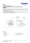
3.1 DESIGN FLOW 1 [ODIN T-VPACK VPR 5.0]
We begin this design flow by using ODIN to synthesize a Verilog file into a netlist of look-up
tables and flip-flops in BLIF format. This netlist is unpacked, so T-VPACK is used to pack the
netlist into logic elements [3]. After packing the netlist, the circuit is placed onto a specified
FPGA architecture using the VPR 5.0 tool suite. Finally, the circuit is optimally routed on the
FPGA using VPR; VPR can perform many types such as detailed and global or combined
global routing [3]. This entire flow is summarized in Figure 1.
Figure 1: ODIN -> T-VPACK -> VPR Flow summary
Flow Procedure
The flow requires access to the ivl, ivlpp, t-vpack and vpr executable binaries. Export paths
for these in the PATH environment variable. The following is a sample PATH variable setting
which may be written in a .bashrc file and can be sourced whenever necessary.
#Path for t-vpack executable binary
PATH=${PATH}:/rcg/mhaines/vpr_5_beta/TOOLS/T-VPACK_HET
#Path for vpr executable binary
PATH=${PATH}:/rcg/mhaines/vpr_5_beta/TOOLS/VPR_HET
#Path for ivlpp executable binary
PATH=${PATH}:/rcg/mhaines/ODIN/verilog-20040606/ivlpp
#Path for ivl executable binary
PATH=${PATH}:/rcg/mhaines/ODIN/verilog-20040606
We illustrate the flow using the benchmark “diffeq_paj_convert,” available from the
CAD Tool and Compiler Repository provided by the University of Massachusetts Amherst
and the University of Wisconsin - Madison.
1. Copy the Verilog file into the directory where you wish to create the flow.
>cp diffeq_paj_convert.v ../../../flow_results/
2. Run the preprocessor tool on the design:
>ivlpp -v -o temp.v <name_of_verilog_file>
Example:
>ivlpp -v -o temp.v diffeq_paj_convert.v
This creates a file called temp.v.
3. To configure ODIN to output a BLIF netlist, we need to change several parameters in
config_file.txt, which you can find in the SAMPLE_FILES folder of the
tgt-odin directory. Open config_file.txt and edit it as follows:
functor:synth
functor:syn-rules
functor:cprop
functor:nodangle
-t:dll
flag:DLL=odin.tgt
flag:vpr
flag:arch=vpr
flag:gdb_spin_point=no
flag:lib=/rcg/mhaines/ODIN/verilog-20040606/
tgt-odin/tech_lib.xml
flag:dynamic_debug_file=/rcg/mhaines/ODIN/verilog-20040606/
tgt-odin/dynamic_debug_file.xml
flag:optimization_file=/rcg/mhaines/ODIN/verilog-20040606/
tgt-odin/optimization_file.xml
out:odin_out.blif
Note:
the
variables
“flag:lib,”
“flag:dynamic_debug_file”
and
“flag:optimization_file” must point to the paths where tech_lib.xml,
dynamic_debug_file.xml and optimization_file.xml are located, if they do not
already. The variable “out:odin_out.blif” can be changed to give your output file a
different name. The “flag:vpr” indicates that ODIN will generate a BLIF netlist.
4. Once config_file.txt has been configured as shown in step 3 above, we can run
the synthesis tool to generate the BLIF netlist. Execute the following command:
>ivl -C <name_of_configuration_file> temp.v
Example:
>ivl -C config_file.txt temp.v
If everything goes well, you should have the desired BLIF file in your directory by now. In
this case, it produces an output file called odin_out.blif.
5. Next, we pack the BLIF output from ODIN to .net format using T-VPACK, as shown:
>t-vpack.exe <input.blif> <output.net> -lut_size <K>
-no_clustering
Example:
>t-vpack.exe odin_out.blif tv_out.net -lut_size 4
-no_clustering
If everything works out well, you will have tv_out.net available for the VPR tool suite.
6. Next, we use VPR to place the circuit. VPR needs the .net file as well as an architecture
file to describe the FPGA. Several architecture files are available in the
CAD Tool and Compiler Repository from which this documentation was probably
downloaded. You may use any of them as input architecture file to the VPR placement
tool; because we selected the no_clustering option, k4-n1.xml works best. A
sample command to place a circuit is shown:
>vpr tv_out.net
../vpr_5_beta/VPR_ARCH_FILES/HET_ARCH_FILES_W_MULT/k4n1.xml vpr.p vpr.r -nodisp -full_stats -inner_num 1
-place_only
You can find more details on using the vpr executable in the VPR manual [3]. If the circuit
is placed successfully, you will have a .p file in your directory.
7. Finally, we route the circuit. A sample command to route the circuit is as shown:
>vpr tv_out.net
../vpr_5_beta/VPR_ARCH_FILES/HET_ARCH_FILES_W_MULT/k4n1.xml vpr.p vpr.r -nodisp -full_stats -fast
-max_router_iterations 10 -router_algorithm breadth_first
-route_type detailed -route_only
The VPR manual [3] can provide details on how to use VPR for routing.
3.2 DESIGN FLOW 2 [ODIN ABC (to optimize) VPR 5.0]
We also begin this design flow by using ODIN to synthesize a Verilog design file into a BLIF
format netlist. Before passing the BLIF file to T-VPACK, however, we use ABC to optimize it.
T-VPACK then packs the optimized BLIF format netlist into logic blocks. Next, we use VPR to
place and route these logic blocks onto an FPGA, whose architecture is specified by an
architecture file; the output is the placement of the logic blocks and the routing of the circuit
on the FPGA. This flow is summarized in Figure 2.
Figure 2: ODIN -> ABC (to optimize) -> VPR Flow summary
Flow Procedure
The flow requires access to the executable binaries for ivl, ivlpp, abc, t-vpack and vpr. The
following is a sample PATH variable setting that exports these to the PATH environment
variable; it can be written in a .bashrc file.
#Path for t-vpack executable binary
PATH=${PATH}:/rcg/mhaines/vpr_5_beta/TOOLS/T-VPACK_HET
#Path for vpr executable binary
PATH=${PATH}:/rcg/mhaines/vpr_5_beta/TOOLS/VPR_HET
#Path for ivlpp executable binary
PATH=${PATH}:/rcg/mhaines/ODIN/verilog-20040606/ivlpp
#Path for executable binary
PATH=${PATH}:/rcg/mhaines/ODIN/verilog-20040606
#Path for abc executable binary
PATH=${PATH}:/rcg/mhaines/abc70930
We illustrate the flow using the benchmark “diffeq_paj_convert,” which you can
download from the CAD Tool and Compiler Repository provided by the University of
Massachusetts Amherst and the University of Wisconsin - Madison.
1. Copy the Verilog file into the directory where you wish to create the flow.
>cp diffeq_paj_convert.v ../../../flow_results/
2. Run the preprocessor tool on the design:
>ivlpp -v -o temp.v <name_of_verilog_file>
Example:
>ivlpp -v -o temp.v diffeq_paj_convert.v
This creates a file called temp.v in the active directory.
3. To configure ODIN to output a BLIF netlist, we need to configure several options in the
configuration file config_file.txt. Open config_file.txt and edit is as follows:
functor:synth
functor:syn-rules
functor:cprop
functor:nodangle
-t:dll
flag:DLL=odin.tgt
flag:vpr
flag:arch=vpr
flag:gdb_spin_point=no
flag:lib=/rcg/mhaines/ODIN/verilog-20040606/tgt-odin/tech_lib.xml
flag:dynamic_debug_file=/rcg/mhaines/ODIN/verilog-20040606/
tgt-odin/dynamic_debug_file.xml
flag:optimization_file=/rcg/mhaines/ODIN/verilog-20040606/
tgt-odin/optimization_file.xml
out:odin_out.blif
Note:
the
variables
“flag:lib,”
“flag:dynamic_debug_file”
and
“flag:optimization_file” must point to the path where tech_lib.xml,
dynamic_debug_file.xml and optimization_file.xml files located. The
variable “out:odin_out.blif” indicates the name of the output file, which you can
change. The “flag:vpr” indicates that ODIN will be configured to generate a BLIF
netlist.
4. Once config_file.txt has been configured as shown in step 3 above, we can run
the synthesis tool to generate the BLIF netlist. Execute the following command:
>ivl -C <name_of_configuration_file> temp.v
Example:
>ivl -C config_file.txt temp.v
If everything goes well, you should have the desired BLIF file in your directory by now.
The name of this BLIF file is specified by config_file.txt; here, it is
odin_out.blif.
5. To optimize the BLIF netlist, we use ABC. You will need to use the abc.rc resource in
the abc70930 directory, so copy abc.rc into the active directory.
> cp ../abc70930/abc.rc abc.rc
6. Now, run the abc executable.
> abc
7. From the ABC prompt, read the un-optimized BLIF file.
UC Berkeley, ABC 1.01 (compiled Jun 6 2008 12:38:36)
abc 01> read_blif <name_of_blif_file>
8. Optimize the BLIF netlist with a script defined in abc.rc, as shown:
abc 02> resyn2rs
9. Write out the optimized netlist.
abc 20> write_blif <name_of_blif_file>
Example:
abc 20> write_blif abc_out.blif
10. Next, we need to add two parameters to the latches so that we can use T-VPACK to pack
the optimized BLIF output into .net format. After you quit out of ABC, change every latch
in the output BLIF file to include the reset signal “re” and clock signal:
abc 20> quit
>vim abc_out.blif
Example change:
Before: .latch
n3365 hetero_REGISTER_2158_7227_out 2
After: .latch
n3365 hetero_REGISTER_2158_7227_out re barrel32_clk_0 2
11. Save the BLIF file. Now, run T-VPACK to pack the BLIF file:
>t-vpack.exe
<input.blif>
-no_clustering
<output.net>
-lut_size
<K>
Example:
>t-vpack.exe
–no_clustering
abc_out.blif
tv_out.net
–lut_size
4
If everything works out well, you will now have a file named tv_out.net.
12. Next, we use VPR to place the circuit. VPR needs the .net file previously generated as
well as an architecture file to describe the circuit. Several architecture files are available
in the CAD Tool and Compiler Repository from which this documentation was probably
downloaded. You may use any of them as input architecture file to the VPR placement
tool; because we selected the no_clustering option, k4-n1.xml works best. A
sample command to place a circuit is shown:
>vpr tv_out.net
../vpr_5_beta/VPR_ARCH_FILES/HET_ARCH_FILES_W_MULT/k4n1.xml vpr.p vpr.r -nodisp -full_stats -inner_num 1
-place_only
More details on using VPR can be found in the VPR manual [3]. If the circuit is placed
successfully, you will have a .p file in your directory.
13. Finally, the circuit needs to be routed, for which we use VPR again. A sample command
to route the circuit is as shown:
>vpr tv_out.net
../vpr_5_beta/VPR_ARCH_FILES/HET_ARCH_FILES_W_MULT/k4n1.xml vpr.p vpr.r -nodisp -full_stats -fast
-max_router_iterations 10 -router_algorithm breadth_first
-route_type detailed -route_only
You can find more details and options on how to use VPR for routing in the VPR
manual [3].
3.3 DESIGN FLOW 3 [ODIN ABC (to optimize and map) VPR 5.0]
This flow is very similar to the one described above. First, ODIN is used to synthesize a
Verilog design into a netlist in BLIF. We then use ABC to optimize the circuit and to map the
circuit, which it was also designed to do. The differences between the results of this flow and
the previous flow will determine whether ABC should be used to this extent. Next, T-VPACK
packs the mapped netlist file into logic units made of look-up tables and flip-flops so that VPR
can place the circuit on an FPGA according to the netlist file and to a specified architecture.
The flow finishes when VPR routes the circuit on the FPGA; Some of the typical routings
offered by the VPR tool are global, or combined global and detailed routing of the circuit[3].
This flow is summarized in Figure 3.
Figure 3: ODIN -> ABC (to optimize and map) -> VPR Flow Summary
Flow Procedure
This flow requires access to the executable binaries for ivl, ivlpp, abc, t-vpack and vpr. Export
these in the PATH environment variable. The following is a example file of a PATH variable
setting that can be written in a .bashrc file.
#Path for t-vpack executable binary
PATH=${PATH}:/rcg/mhaines/vpr_5_beta/TOOLS/T-VPACK_HET
#Path for vpr executable binary
PATH=${PATH}:/rcg/mhaines/vpr_5_beta/TOOLS/VPR_HET
#Path for ivlpp executable binary
PATH=${PATH}:/rcg/mhaines/ODIN/verilog-20040606/ivlpp
#Path for executable binary
PATH=${PATH}:/rcg/mhaines/ODIN/verilog-20040606
#Path for abc executable binary
PATH=${PATH}:/rcg/mhaines/abc70930
We illustrate the flow using the benchmark “diffeq_paj_convert,” which you can find in
the CAD Tool and Compiler Repository provided by the University of Massachusetts Amherst
and the University of Wisconsin - Madison.
1. Copy the Verilog file into the directory where you wish to create the flow.
>cp diffeq_paj_convert.v ../../../flow_results/
2. Run the preprocessor tool on the design:
>ivlpp -v -o temp.v <name_of_verilog_file>
Example:
>ivlpp -v -o temp.v diffeq_paj_convert.v
This creates a file called temp.v in the active directory.
3. To configure ODIN to output a BLIF netlist, we need to configure several options in the
configuration file config_file.txt. Open config_file.txt and edit it as follows:
functor:synth
functor:syn-rules
functor:cprop
functor:nodangle
-t:dll
flag:DLL=odin.tgt
flag:vpr
flag:arch=vpr
flag:gdb_spin_point=no
flag:lib=/rcg/mhaines/ODIN/verilog-20040606/tgt-odin/tech_lib.xml
flag:dynamic_debug_file=/rcg/mhaines/ODIN/verilog-20040606/
tgt-odin/dynamic_debug_file.xml
flag:optimization_file=/rcg/mhaines/ODIN/verilog-20040606/
tgt-odin/optimization_file.xml
out:odin_out.blif
Note:
the
variables
“flag:lib,”
“flag:optimization_file” must point
“flag:dynamic_debug_file”
and
to the path where tech_lib.xml,
dynamic_debug_file.xml and optimization_file.xml are located. The variable
“out:odin_out.blif” indicates the name of the output file, which your can change.
The “flag:vpr” variable indicates that ODIN will be configured to generate a BLIF
netlist.
4. Once config_file.txt has been configured as shown in the step above, we can run
the synthesis tool to generate the BLIF netlist, as shown:
>ivl -C <name_of_configuration_file> temp.v
Example:
>ivl -C config_file.txt temp.v
If everything goes well, you should have the desired BLIF file in your directory by now;
here, it would be odin_out.blif.
5. To optimize the BLIF netlist, we use ABC. You may find that you need to use the abc.rc
resource for this, so copy abc.rc into the active directory.
> cp ../abc70930/abc.rc abc.rc
6. ABC can also be used to map the BLIF netlist, so before running ABC, make a new file
called abc_Mapper.txt in the same directory. Copy the following line (about 30-40
times) into the file.
choice; fpga;
If you want to print statistics on any line in the file, add “ ps;” to that line:
7. Start ABC by running the abc executable.
> abc
8. From the prompt, read the un-optimized BLIF file.
UC Berkeley, ABC 1.01 (compiled Jun 6 2008 12:38:36)
abc 01> read_blif <name_of_blif_file>
9. Optimize the BLIF file with one of the scripts defined in abc.rc, as shown:
abc 02> resyn2rs
10. Next, source abc_Mapper.txt to map the circuit.
abc 20> source abc_Mapper.txt
11. Write out the optimized netlist and quit ABC.
abc 740> write_blif <name_of_output_blif_file>
abc 740> quit
12. Next, we need to add two parameters to the latches so that we can use T-VPACK to pack
the optimized BLIF output into .net format. Open the output BLIF file, which is
abc_out.blif in this case, and change every latch in the output BLIF file to include the
reset signal and clock signal:
abc 20> quit
>vim abc_out.blif
Example Change:
Before: .latch
n3365 hetero_REGISTER_2158_7227_out 2
After: .latch
n3365 hetero_REGISTER_2158_7227_out re barrel32_clk_0 2
13. Save the BLIF file. Now, pack the optimized and mapped BLIF file to .net format using
T-VPACK:
>t-vpack.exe
<input.blif>
-no_clustering
<output.net>
-lut_size
<K>
Example:
>t-vpack.exe
–no_clustering
abc_out.blif
tv_out.net
–lut_size
4
If everything works out well, you will have the file tv_out.net available now; it can be
fed into the VPR placement and routing tools.
14. Next, we use VPR to place the circuit. VPR needs the .net file as well as an architecture
file to describe the circuit. Several architecture files are available in the
CAD Tool and Compiler Repository from which this documentation was probably
downloaded. You may use any of them as input architecture file to the VPR placement
tool; because we selected the no_clustering option, k4-n1.xml works best. A
sample command to place a circuit is shown:
>vpr tv_out.net
../vpr_5_beta/VPR_ARCH_FILES/HET_ARCH_FILES_W_MULT/k4n1.xml vpr.p vpr.r -nodisp -full_stats -inner_num 1
-place_only
You can find more details on using VPR in the VPR manual [3]. If the circuit is placed
successfully, you will have a .p file in your directory.
15. Finally, route the circuit. A sample command to route the circuit is as shown:
>vpr tv_out.net
../vpr_5_beta/VPR_ARCH_FILES/HET_ARCH_FILES_W_MULT/k4n1.xml vpr.p vpr.r -nodisp -full_stats -fast
-max_router_iterations 10 -router_algorithm breadth_first
-route_type detailed -route_only
More details and options on how to use VPR for routing can be found in the VPR
manual [3].
3.4 DESIGN FLOW 4 [ODIN ABC QUIP]
This flow also begins by synthesizing the Verilog design into a BLIF netlist with the ODIN RTL
Compiler. Next, ABC optimizes and maps the netlist before converting it into a Verilog file.
Lastly, QUIP is used to compile the modified Verilog file. This flow is summarized in Figure 4.
Figure 4: ODIN -> ABC -> QUIP
Flow Procedure
This flow requires access to the ivl, ivlpp, and abc executables. Export paths to each of these
in the PATH environment variable; the following code shows how this can be set in a .bashrc
file.
#Path for ivlpp executable binary
PATH=${PATH}:/rcg/mhaines/ODIN/verilog-20040606/ivlpp
#Path for executable binary
PATH=${PATH}:/rcg/mhaines/ODIN/verilog-20040606
#Path for ABC executable binary
PATH=${PATH}:/rcg/mhaines/abc70930
We illustrate the flow using the benchmark “diffeq_paj_convert,” which the
CAD Tool and Compiler Repository provides.
1. Copy the Verilog file into the directory where you wish to create the flow.
>cp diffeq_paj_convert.v ../../../flow_results/
2. Run the preprocessor tool on the design:
>ivlpp -v -o temp.v <name_of_verilog_file>
Example:
>ivlpp -v -o temp.v diffeq_paj_convert.v
This creates a file called temp.v in the active directory.
3. To configure ODIN to output a BLIF netlist, we need to change configure several options
in the configuration file config_file.txt. Open config_file.txt and edit it as
shown:
functor:synth
functor:syn-rules
functor:cprop
functor:nodangle
-t:dll
flag:DLL = odin.tgt
flag:vpr
flag:arch=vpr
flag:gdb_spin_point=no
flag:lib=/rcg/mhaines/ODIN/verilog-20040606/
tgt-odin/tech_lib.xml
flag:dynamic_debug_file=/rcg/mhaines/ODIN/verilog-20040606/
tgt-odin/dynamic_debug_file.xml
flag:optimization_file=/rcg/mhaines/ODIN/verilog-20040606/
tgt-odin/optimization_file.xml
out:odin_out.blif
Note:
the
variables
“flag:lib”,
“flag:dynamic_debug_file”
and
“flag:optimization_file” must point to the path where your tech_lib.xml,
dynamic_debug_file.xml and optimization_file.xml are located. The variable
“out:odin_out.blif” indicates the name of your output file, which you can change.
The “flag:vpr” indicates that ODIN will be configured to generate a BLIF netlist.
4. Once config_file.txt has been configured as shown in step 3 above, run the
synthesis tool to generate the BLIF netlist, as shown:
>ivl -C <name_of_configuration_file> temp.v
Example:
>ivl -C config_file.txt temp.v
If everything goes well, you should have the desired BLIF file in your directory by now;
here, it is named odin_out.blif.
5. To optimize the BLIF netlist, you may need to use a script defined in the abc.rc
resource in the abc70930 directory. Copy abc.rc into the active directory.
> cp ../abc70390/abc.rc abc.rc
6. Because we are using ABC to map the BLIF netlist, you may prefer to write a new file
called abc_Mapper.txt in the same directory before running ABC. Copy the following
line (about 30-40 times) into the file.
choice; fpga;
If you want to print statistics on any line in the file, add “ ps;” to that line:
7. Start ABC by running the abc executable.
> abc
8. From the prompt, first read the un-optimized BLIF file
> UC Berkeley, ABC 1.01 (compiled Jun
abc 01> read_blif <name_of_blif_file>
6 2008 12:38:36)
9. Use one of the scripts defined in abc.rc to optimize the BLIF netlist.
abc 02> resyn2rs
10. Next, source abc_Mapper.txt to map the circuit.
abc 20> source abc_Mapper.txt
11. ABC can be used to convert the result into a Verilog file. You do not need to write the
optimized BLIF file to do this; instead, type the following command:
abc 740> write_verilog <verilog_output_file>
The following example writes the Verilog file in the abc70930 folder. Notice that the
output file has the same name as the benchmark; QUIP requires that the file and the top
module have the same name, and ABC will maintain the original name of the top module.
abc 740> write_verilog ../abc70930/diffeq_paj_convert.v
12. Quit out of ABC and create a new directory in Windows. Copy the Verilog file, which is
diffeq_paj_convert.v in this case, to the new directory.
13. Create a new Quartus Project. Add the Verilog file to the project and run the compilation.
If you encounter any difficulty, you should be able to find sufficient help in the Quartus II
Tutorial [5].
4. RESULTS
Table 3 gives the placement and routing results obtained after compiling three
benchmark circuits with the first three CAD flows presented in this paper. Note that Flow 1
corresponds to the first flow presented, Flow 2 to the second, and Flow 3 to the third.
Benchmark
Circuit
Flow
diffeq_paj_
convert
1
2
3
cf_fir_
3_8_8
1
2
3
Placement
Logical
Critical
Block
Path
Array
Delay
90 x 90
112.992 ns
133 x 133 304.039 ns
83 x 83
78.1775 ns
48 x 48
53 x 53
33 x 33
19.6508 ns
53.7059 ns
15.4285 ns
Width
12
12
20
10
12
Routing
Total
Total Logic
Routing
Area
Area
6
243*10
3.41103*106
6
530.67*10
7.34920*106
6
206.67*10
3.76124*106
84.27*106
32.67*106
630,931
476,537
Critical
Path
Delay
119.643 ns
314.377 ns
86.5717 ns
60.8692 ns
17.1117 ns
1
206 x 206 63.6324 ns
2
261 x 261 181.11 ns
14
2043.63*106 28.7214*106 206.573 ns
3
162 x 162 45.2814 ns
20
787.32*106
14.2713*106 51.2737 ns
Table 3: Results of proposed design flows 1, 2, and 3 on three benchmark circuits
cf_fir_
24_16_16
Note 1: All three benchmarks are available in the CAD Tool and Compiler Repository provided by
the University of Massachusetts Amherst and the University of Wisconsin - Madison.
Note 2: Two of the benchmarks were unable to be compiled through the VPR 5.0 router when
they were unoptimized; the reason for this is currently unknown, but it is believed to be because
of a limitation of VPR 5.0.
REFERENCES
[1] UMass Amherst Reconfigurable Computing Group, “CRI: CRD Collaborative Research: CAD
Tool and Compiler Repository for Reconfigurable Computing: CAD Flows”, 2008
[2] Berkeley Logic Synthesis and Verification Group, “ABC: A System for Sequential Synthesis
and Verification,” Release 70930. http://www.eecs.berkeley.edu/~alanmi/abc/
[3] V. Betz, J. Rose, “VPR and T-VPACK User’s Manual”, http://www.eecg.toronto.edu/vpr/
2008.
[4] P. Jamieson and J. Rose, “A Verilog RTL Synthesis Tool for FPGAs”, International
Conference on Field Programmable Logic and Applications, 2005
[5] Quartus II University Interface Program Tutorial, Altera Corporation, 2005
Known limitations:
1. This flow cannot handle memory blocks.
2. These benchmark circuits suffer from certain problems:
Circuit
Problem
Solution
sv_chip0...
Line is too long for
Break input buffer
input buffer
into several lines.
sv_chip1...
Names are too long
Make shorter names