1
VRC 4000
Software Driver Manual
Click on red text at any location in the manual to jump to the
specified chapter, topic, or reference.
About This Manual
Table of Contents
Index
Copyright
70-19723-01
Revision A
February 1997
ii
VRC 4000
Software Driver Manual
70-19723-01
Revision A
February, 1997
1996, 1997 by Symbol Technologies, Inc. All rights reserved.
No part of this publication may be reproduced or used in any form, or by any electrical or
mechanical means, without permission in writing from Symbol. This includes electronic
or mechanical means, such as photocopying, recording, or information storage and
retrieval systems. The material in this manual is subject to change without notice.
The software is provided strictly on an “as is” basis. All software, including firmware,
furnished to the user is on a licensed basis. Symbol grants to the user a non-transferable
and non-exclusive license to use each software or firmware program delivered hereunder
(licensed program). Except as noted below, such license may not be assigned, sublicensed,
or otherwise transferred by the user without prior written consent of Symbol. No right to
copy a licensed program in whole or in part is granted, except as permitted under
copyright law. The user shall not modify, merge, or incorporate any form or portion of a
licensed program with other program material, create a derivative work from a licensed
program, or use a licensed program in a network without written permission from Symbol.
The user agrees to maintain Symbol’s copyright notice on the licensed programs delivered
hereunder, and to include the same on any authorized copies it makes, in whole or in part.
The user agrees not to decompile, disassemble, decode, or reverse engineer any licensed
program delivered to the user or any portion thereof.
Symbol reserves the right to make changes to any software or product to improve
reliability, function, or design.
Symbol does not assume any product liability arising out of, or in connection with, the
application or use of any product, circuit, or application described herein.
No license is granted, either expressly or by implication, estoppel, or otherwise under any
Symbol Technologies, Inc., intellectual property rights. An implied license only exists for
equipment, circuits, and subsystems contained in Symbol products.
Symbol and Spectrum One are registered trademarks of Symbol Technologies, Inc.
Other product names mentioned in this manual may be trademarks or registered
trademarks of their respective companies and are hereby acknowledged.
Symbol Technologies, Inc.
One Symbol Plaza
Holtsville, N.Y. 11742
http://www.symbol.com
iv
About This Manual
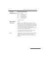
This manual provides information for the software developer writing
programs for use with the VRC 4000. This manual describes the installation
and use of the TWdriver for Windows and the TBdriver for DOS with the VRC
4000 terminal. Included are sections on the required switch settings and
hardware notes, programming guidelines, tips on using multiple touchscreens,
and instructions on using the TWdriver Application Programming Interface.
The following are the specific chapter/appendix titles along with brief
descriptions of the contents of each:
Chapter 1, TWDriver Touchscreen Driver for Windows, describes the installation
methods for installing the TWDriver, and provides additional information on
calibration and troubleshooting.
Chapter 2, TBDriver Touchscreen Driver for DOS, provides similar information
for installing and configuring TBDriver for DOS, including instructions on
unloading the driver and calibration.
Appendix A, TWDriver Switch Settings and Hardware Notes, describes required
switch settings for use with various controllers, as well as some additional
hardware notes.
Appendix B, TBDriver Switch Settings and Hardware Notes, provides similar
information for use with TBDriver.
Appendix C, Using Multiple Touchscreens, provides information on using
multiple touchscreens, including instructions on using a matrix touchscreen.
Appendix D, Programming Guidelines, describes some techniques commonly
employed in touchscreen programming.
Appendix E, TWDriver Application Programming Interface, describes the use of
the API, and includes explanations of each of the function calls.
v
vi
Contents
TWDriver Touchscreen Driver for Windows
1-1
Introduction . . . . . . . . . . . . . . . . . . . . . . . . . . . . . . . . . . . . . . . . . . . . . . . . . . . . . . . . . . . . . . . . . . . . . 1-3
Getting Started . . . . . . . . . . . . . . . . . . . . . . . . . . . . . . . . . . . . . . . . . . . . . . . . . . . . . . . . . . . . . . . . . . . 1-4
Installation . . . . . . . . . . . . . . . . . . . . . . . . . . . . . . . . . . . . . . . . . . . . . . . . . . . . . . . . . . . . . . . . . . 1-4
Alternative Installation Methods . . . . . . . . . . . . . . . . . . . . . . . . . . . . . . . . . . . . . . . . . . . . . . . 1-7
Windows Double Click Speed . . . . . . . . . . . . . . . . . . . . . . . . . . . . . . . . . . . . . . . . . . . . . . . . . 1-8
Windows Border Width . . . . . . . . . . . . . . . . . . . . . . . . . . . . . . . . . . . . . . . . . . . . . . . . . . . . . . . 1-8
Hardware Installation . . . . . . . . . . . . . . . . . . . . . . . . . . . . . . . . . . . . . . . . . . . . . . . . . . . . . . . . 1-9
Calibration . . . . . . . . . . . . . . . . . . . . . . . . . . . . . . . . . . . . . . . . . . . . . . . . . . . . . . . . . . . . . . . . . . 1-9
Configuration . . . . . . . . . . . . . . . . . . . . . . . . . . . . . . . . . . . . . . . . . . . . . . . . . . . . . . . . . . . . . . . 1-9
Button Modes - Pre-Defined . . . . . . . . . . . . . . . . . . . . . . . . . . . . . . . . . . . . . . . . . . . . . . . . . . 1-11
Co-existence with Mice . . . . . . . . . . . . . . . . . . . . . . . . . . . . . . . . . . . . . . . . . . . . . . . . . . . . . . . . . . 1-26
Co-existence with DOS TBdriver . . . . . . . . . . . . . . . . . . . . . . . . . . . . . . . . . . . . . . . . . . . . . . . . . . 1-26
Troubleshooting and Technical Support . . . . . . . . . . . . . . . . . . . . . . . . . . . . . . . . . . . . . . . . . . . . 1-27
No cursor movement when touchscreen touched . . . . . . . . . . . . . . . . . . . . . . . . . . . . . . . . 1-27
Cursor moves but incorrectly . . . . . . . . . . . . . . . . . . . . . . . . . . . . . . . . . . . . . . . . . . . . . . . . . 1-27
Difficulties with double clicks . . . . . . . . . . . . . . . . . . . . . . . . . . . . . . . . . . . . . . . . . . . . . . . . . 1-28
System performance . . . . . . . . . . . . . . . . . . . . . . . . . . . . . . . . . . . . . . . . . . . . . . . . . . . . . . . . . 1-28
TBdiag - The Touchscreen Diagnostic Program . . . . . . . . . . . . . . . . . . . . . . . . . . . . . . . . . . 1-28
The TBdiag Command Line . . . . . . . . . . . . . . . . . . . . . . . . . . . . . . . . . . . . . . . . . . . . . . . . . . 1-29
Service Information . . . . . . . . . . . . . . . . . . . . . . . . . . . . . . . . . . . . . . . . . . . . . . . . . . . . . . . . . . . . . 1-31
Symbol Support Center . . . . . . . . . . . . . . . . . . . . . . . . . . . . . . . . . . . . . . . . . . . . . . . . . . . . . . 1-31
USA . . . . . . . . . . . . . . . . . . . . . . . . . . . . . . . . . . . . . . . . . . . . . . . . . . . . . . . . . . . . . . . . . . . . . . . 1-31
Canada . . . . . . . . . . . . . . . . . . . . . . . . . . . . . . . . . . . . . . . . . . . . . . . . . . . . . . . . . . . . . . . . . . . . 1-31
Europe . . . . . . . . . . . . . . . . . . . . . . . . . . . . . . . . . . . . . . . . . . . . . . . . . . . . . . . . . . . . . . . . . . . . . 1-31
Asia . . . . . . . . . . . . . . . . . . . . . . . . . . . . . . . . . . . . . . . . . . . . . . . . . . . . . . . . . . . . . . . . . . . . . . . 1-32
TBDriver Touchscreen Driver for DOS
2-1
Introduction . . . . . . . . . . . . . . . . . . . . . . . . . . . . . . . . . . . . . . . . . . . . . . . . . . . . . . . . . . . . . . . . . . . . . 2-3
Getting Started . . . . . . . . . . . . . . . . . . . . . . . . . . . . . . . . . . . . . . . . . . . . . . . . . . . . . . . . . . . . . . . . . . . 2-5
Concepts . . . . . . . . . . . . . . . . . . . . . . . . . . . . . . . . . . . . . . . . . . . . . . . . . . . . . . . . . . . . . . . . . . . . . . . . 2-8
Application Programming Interface . . . . . . . . . . . . . . . . . . . . . . . . . . . . . . . . . . . . . . . . . . . . 2-8
Touch Input Data . . . . . . . . . . . . . . . . . . . . . . . . . . . . . . . . . . . . . . . . . . . . . . . . . . . . . . . . . . . . 2-8
Application Programming Interface . . . . . . . . . . . . . . . . . . . . . . . . . . . . . . . . . . . . . . . . . . . . . . . 2-17
Before Calling The API . . . . . . . . . . . . . . . . . . . . . . . . . . . . . . . . . . . . . . . . . . . . . . . . . . . . . . . 2-17
Loading and Unloading TBDRIVER . . . . . . . . . . . . . . . . . . . . . . . . . . . . . . . . . . . . . . . . . . . . . . . 2-47
The TBdriver Command Line . . . . . . . . . . . . . . . . . . . . . . . . . . . . . . . . . . . . . . . . . . . . . . . . . 2-47
Unloading TBdriver . . . . . . . . . . . . . . . . . . . . . . . . . . . . . . . . . . . . . . . . . . . . . . . . . . . . . . . . . 2-52
TBdriver Messages . . . . . . . . . . . . . . . . . . . . . . . . . . . . . . . . . . . . . . . . . . . . . . . . . . . . . . . . . . . . . . 2-53
TBdriver Return Codes . . . . . . . . . . . . . . . . . . . . . . . . . . . . . . . . . . . . . . . . . . . . . . . . . . . . . . 2-55
vii
The TBdriver Demonstration Program . . . . . . . . . . . . . . . . . . . . . . . . . . . . . . . . . . . . . . . . . . . . .
The TBdriver Calibration Program . . . . . . . . . . . . . . . . . . . . . . . . . . . . . . . . . . . . . . . . . . . . . . . .
Hard Calibrate . . . . . . . . . . . . . . . . . . . . . . . . . . . . . . . . . . . . . . . . . . . . . . . . . . . . . . . . . . . . . .
Options 1 - 9 . . . . . . . . . . . . . . . . . . . . . . . . . . . . . . . . . . . . . . . . . . . . . . . . . . . . . . . . . . . . . . . .
Test Menu . . . . . . . . . . . . . . . . . . . . . . . . . . . . . . . . . . . . . . . . . . . . . . . . . . . . . . . . . . . . . . . . . .
Customize Video Mode Mappings . . . . . . . . . . . . . . . . . . . . . . . . . . . . . . . . . . . . . . . . . . . .
Troubleshooting and Technical Support . . . . . . . . . . . . . . . . . . . . . . . . . . . . . . . . . . . . . . . . . . . .
TBDIAG - The Touchscreen Diagnostic Program . . . . . . . . . . . . . . . . . . . . . . . . . . . . . . . . . . . .
The TBdiag Command Line . . . . . . . . . . . . . . . . . . . . . . . . . . . . . . . . . . . . . . . . . . . . . . . . . .
How To Contact Technical Support . . . . . . . . . . . . . . . . . . . . . . . . . . . . . . . . . . . . . . . . . . . .
TBMOUSE - The Mouse Emulator . . . . . . . . . . . . . . . . . . . . . . . . . . . . . . . . . . . . . . . . . . . . . . . . .
The TBmouse Command Line . . . . . . . . . . . . . . . . . . . . . . . . . . . . . . . . . . . . . . . . . . . . . . . .
Button Emulation Modes . . . . . . . . . . . . . . . . . . . . . . . . . . . . . . . . . . . . . . . . . . . . . . . . . . . . .
The Mouse Cursor . . . . . . . . . . . . . . . . . . . . . . . . . . . . . . . . . . . . . . . . . . . . . . . . . . . . . . . . . .
Absolute Mode . . . . . . . . . . . . . . . . . . . . . . . . . . . . . . . . . . . . . . . . . . . . . . . . . . . . . . . . . . . . .
Relative Mode . . . . . . . . . . . . . . . . . . . . . . . . . . . . . . . . . . . . . . . . . . . . . . . . . . . . . . . . . . . . . .
The Mickey to Pixel Ratio . . . . . . . . . . . . . . . . . . . . . . . . . . . . . . . . . . . . . . . . . . . . . . . . . . . .
Initial Virtual Screen Size . . . . . . . . . . . . . . . . . . . . . . . . . . . . . . . . . . . . . . . . . . . . . . . . . . . . .
Initial cursor position . . . . . . . . . . . . . . . . . . . . . . . . . . . . . . . . . . . . . . . . . . . . . . . . . . . . . . . .
Incremental Motion . . . . . . . . . . . . . . . . . . . . . . . . . . . . . . . . . . . . . . . . . . . . . . . . . . . . . . . . .
Alternate Interpretation of x,y Limits . . . . . . . . . . . . . . . . . . . . . . . . . . . . . . . . . . . . . . . . . .
Ignoring Touches Outside x,y Limits . . . . . . . . . . . . . . . . . . . . . . . . . . . . . . . . . . . . . . . . . . .
Stack Switching . . . . . . . . . . . . . . . . . . . . . . . . . . . . . . . . . . . . . . . . . . . . . . . . . . . . . . . . . . . . .
The Z Axis . . . . . . . . . . . . . . . . . . . . . . . . . . . . . . . . . . . . . . . . . . . . . . . . . . . . . . . . . . . . . . . . .
Acceleration and Other Problems . . . . . . . . . . . . . . . . . . . . . . . . . . . . . . . . . . . . . . . . . . . . .
Unloading TBmouse . . . . . . . . . . . . . . . . . . . . . . . . . . . . . . . . . . . . . . . . . . . . . . . . . . . . . . . . .
TBmouse Messages . . . . . . . . . . . . . . . . . . . . . . . . . . . . . . . . . . . . . . . . . . . . . . . . . . . . . . . . . .
Return Codes . . . . . . . . . . . . . . . . . . . . . . . . . . . . . . . . . . . . . . . . . . . . . . . . . . . . . . . . . . . . . . .
TBmouse Extended Application Program Interface . . . . . . . . . . . . . . . . . . . . . . . . . . . . . .
TBmouse Application Support . . . . . . . . . . . . . . . . . . . . . . . . . . . . . . . . . . . . . . . . . . . . . . . .
TBPAD - The Keyboard Emulator . . . . . . . . . . . . . . . . . . . . . . . . . . . . . . . . . . . . . . . . . . . . . . . . .
The TBpad Demonstration . . . . . . . . . . . . . . . . . . . . . . . . . . . . . . . . . . . . . . . . . . . . . . . . . . .
The TBpad Application Programming Interface . . . . . . . . . . . . . . . . . . . . . . . . . . . . . . . . .
TWDriver
Switch Settings and Hardware Notes
2-56
2-61
2-62
2-62
2-64
2-65
2-68
2-69
2-69
2-71
2-72
2-73
2-74
2-74
2-75
2-75
2-75
2-77
2-77
2-77
2-78
2-78
2-78
2-78
2-78
2-79
2-79
2-81
2-82
2-87
2-88
2-88
2-94
A-1
Introduction . . . . . . . . . . . . . . . . . . . . . . . . . . . . . . . . . . . . . . . . . . . . . . . . . . . . . . . . . . . . . . . . . . . . . A-3
Brady TSD-SI Touchscreen . . . . . . . . . . . . . . . . . . . . . . . . . . . . . . . . . . . . . . . . . . . . . . . . . . . . A-4
Carroll Touch HBC bus controller . . . . . . . . . . . . . . . . . . . . . . . . . . . . . . . . . . . . . . . . . . . . . . A-4
CompuAdd POS Terminal . . . . . . . . . . . . . . . . . . . . . . . . . . . . . . . . . . . . . . . . . . . . . . . . . . . . A-4
Dale Touchscreen . . . . . . . . . . . . . . . . . . . . . . . . . . . . . . . . . . . . . . . . . . . . . . . . . . . . . . . . . . . . A-5
Dynapro . . . . . . . . . . . . . . . . . . . . . . . . . . . . . . . . . . . . . . . . . . . . . . . . . . . . . . . . . . . . . . . . . . . . A-5
Ellinor Touchscreen . . . . . . . . . . . . . . . . . . . . . . . . . . . . . . . . . . . . . . . . . . . . . . . . . . . . . . . . . . A-5
viii
Elographics Accutouch - CRC Controller . . . . . . . . . . . . . . . . . . . . . . . . . . . . . . . . . . . . . . . . A-5
Elographics Accutouch - PC Bus Controller . . . . . . . . . . . . . . . . . . . . . . . . . . . . . . . . . . . . . . A-5
Elographics AccuTouch - RS232 Controller . . . . . . . . . . . . . . . . . . . . . . . . . . . . . . . . . . . . . . A-6
Elographics DuraTouch . . . . . . . . . . . . . . . . . . . . . . . . . . . . . . . . . . . . . . . . . . . . . . . . . . . . . . . A-6
Elographics E271-2201 PC-Bus Touchscreen Controller . . . . . . . . . . . . . . . . . . . . . . . . . . . A-6
Elographics IntelliTouch - PC Bus Controller . . . . . . . . . . . . . . . . . . . . . . . . . . . . . . . . . . . . . A-6
Elographics IntelliTouch - RS232 Controller . . . . . . . . . . . . . . . . . . . . . . . . . . . . . . . . . . . . . . A-7
Elographics E271-2201 PC Bus Controller . . . . . . . . . . . . . . . . . . . . . . . . . . . . . . . . . . . . . . . . A-7
IBM 4655 POS Terminal . . . . . . . . . . . . . . . . . . . . . . . . . . . . . . . . . . . . . . . . . . . . . . . . . . . . . . . A-8
Intasolve Touch . . . . . . . . . . . . . . . . . . . . . . . . . . . . . . . . . . . . . . . . . . . . . . . . . . . . . . . . . . . . . . A-8
ISI Crystal Clear . . . . . . . . . . . . . . . . . . . . . . . . . . . . . . . . . . . . . . . . . . . . . . . . . . . . . . . . . . . . . A-8
MA Systems & Design - Serial Controller . . . . . . . . . . . . . . . . . . . . . . . . . . . . . . . . . . . . . . . . A-9
Quick Analogue Resistive, Firmware Rev 1.2 . . . . . . . . . . . . . . . . . . . . . . . . . . . . . . . . . . . . A-9
Touch Technology AR5000/Digitouch . . . . . . . . . . . . . . . . . . . . . . . . . . . . . . . . . . . . . . . . . . A-9
Touch Technology PC2000 Bus Controller . . . . . . . . . . . . . . . . . . . . . . . . . . . . . . . . . . . . . . . A-9
Touch Technology PC5000 Bus Controller . . . . . . . . . . . . . . . . . . . . . . . . . . . . . . . . . . . . . . . A-9
Touch Technology RS2000 Serial Controller . . . . . . . . . . . . . . . . . . . . . . . . . . . . . . . . . . . . . A-10
Touch Technology TekTouch . . . . . . . . . . . . . . . . . . . . . . . . . . . . . . . . . . . . . . . . . . . . . . . . . A-1 0
Wasp TSI 5000/4 BC - PC Bus Controller . . . . . . . . . . . . . . . . . . . . . . . . . . . . . . . . . . . . . . . A-10
Automatic Re-initialization . . . . . . . . . . . . . . . . . . . . . . . . . . . . . . . . . . . . . . . . . . . . . . . . . . . A-10
TBDriver
Switch Settings and Hardware Notes
B-1
Introduction . . . . . . . . . . . . . . . . . . . . . . . . . . . . . . . . . . . . . . . . . . . . . . . . . . . . . . . . . . . . . . . . . . . . . B-3
PC-Bus Touchscreens Controllers . . . . . . . . . . . . . . . . . . . . . . . . . . . . . . . . . . . . . . . . . . . . . . B-3
Automatic Re-initialisation . . . . . . . . . . . . . . . . . . . . . . . . . . . . . . . . . . . . . . . . . . . . . . . . . . . . B-3
Delta Mode Touchscreens . . . . . . . . . . . . . . . . . . . . . . . . . . . . . . . . . . . . . . . . . . . . . . . . . . . . . B-3
Brady TSD-SI Touchscreen . . . . . . . . . . . . . . . . . . . . . . . . . . . . . . . . . . . . . . . . . . . . . . . . . . . . B-4
Carroll Touch HBC bus controller. . . . . . . . . . . . . . . . . . . . . . . . . . . . . . . . . . . . . . . . . . . . . . . B-4
Carroll Touch SBC bus controller . . . . . . . . . . . . . . . . . . . . . . . . . . . . . . . . . . . . . . . . . . . . . . . B-4
CompuAdd POS Terminal . . . . . . . . . . . . . . . . . . . . . . . . . . . . . . . . . . . . . . . . . . . . . . . . . . . . B-4
Dale Touchscreen . . . . . . . . . . . . . . . . . . . . . . . . . . . . . . . . . . . . . . . . . . . . . . . . . . . . . . . . . . . . B-4
Dynapro - Serial, not SC3 . . . . . . . . . . . . . . . . . . . . . . . . . . . . . . . . . . . . . . . . . . . . . . . . . . . . . . B-4
Dynapro - Bus . . . . . . . . . . . . . . . . . . . . . . . . . . . . . . . . . . . . . . . . . . . . . . . . . . . . . . . . . . . . . . . B-5
Ellinor Touchscreen . . . . . . . . . . . . . . . . . . . . . . . . . . . . . . . . . . . . . . . . . . . . . . . . . . . . . . . . . . B-5
Elographics Accutouch - CRC Controller . . . . . . . . . . . . . . . . . . . . . . . . . . . . . . . . . . . . . . . . B-5
Elographics Accutouch E271-141 PC Bus Controller . . . . . . . . . . . . . . . . . . . . . . . . . . . . . . . B-5
Elographics AccuTouch E271-140 Serial Controller . . . . . . . . . . . . . . . . . . . . . . . . . . . . . . . B-6
Elographics DuraTouch E261-280 Serial Controller . . . . . . . . . . . . . . . . . . . . . . . . . . . . . . . B-6
Elographics E271-2201 PC-Bus Controller . . . . . . . . . . . . . . . . . . . . . . . . . . . . . . . . . . . . . . . B-6
Elographics E271-2202 Micro Channel Bus Controller . . . . . . . . . . . . . . . . . . . . . . . . . . . . . B-6
Elographics E281-2300 Serial Controller . . . . . . . . . . . . . . . . . . . . . . . . . . . . . . . . . . . . . . . . . B-7
Elographics IntelliTouch E281-4025 PC Bus Controller . . . . . . . . . . . . . . . . . . . . . . . . . . . . B-7
ix
Elographics IntelliTouch E281-4001/4002 Serial Controllers . . . . . . . . . . . . . . . . . . . . . . . . B-7
ExZec Guided Acoustic Wave Touchscreen . . . . . . . . . . . . . . . . . . . . . . . . . . . . . . . . . . . . . . B-8
IBM 4655 POS Terminal . . . . . . . . . . . . . . . . . . . . . . . . . . . . . . . . . . . . . . . . . . . . . . . . . . . . . . . B-8
Intasolve Touch - Series 100 . . . . . . . . . . . . . . . . . . . . . . . . . . . . . . . . . . . . . . . . . . . . . . . . . . . B-8
Intasolve Touch - Series 200 . . . . . . . . . . . . . . . . . . . . . . . . . . . . . . . . . . . . . . . . . . . . . . . . . . . B-8
ISI Crystal Clear . . . . . . . . . . . . . . . . . . . . . . . . . . . . . . . . . . . . . . . . . . . . . . . . . . . . . . . . . . . . . B-8
Keytec Magic Touch TS-232-B . . . . . . . . . . . . . . . . . . . . . . . . . . . . . . . . . . . . . . . . . . . . . . . . . . B-9
MA Systems & Design - PC Bus Controller . . . . . . . . . . . . . . . . . . . . . . . . . . . . . . . . . . . . . . B-9
MA Systems & Design - Serial Controller . . . . . . . . . . . . . . . . . . . . . . . . . . . . . . . . . . . . . . . . B-9
Quick Analogue Resistive, Firmware Rev 1.2 . . . . . . . . . . . . . . . . . . . . . . . . . . . . . . . . . . . . B-9
RGB Dynamics Matrix Capacitive . . . . . . . . . . . . . . . . . . . . . . . . . . . . . . . . . . . . . . . . . . . . . B-10
Simple Matrix . . . . . . . . . . . . . . . . . . . . . . . . . . . . . . . . . . . . . . . . . . . . . . . . . . . . . . . . . . . . . . B-10
Thomson Tubes Electroniques . . . . . . . . . . . . . . . . . . . . . . . . . . . . . . . . . . . . . . . . . . . . . . . . B-10
Touch Technology AR5000 and Digitouch . . . . . . . . . . . . . . . . . . . . . . . . . . . . . . . . . . . . . . B-10
Touch Technology PC2000 PC Bus Controller . . . . . . . . . . . . . . . . . . . . . . . . . . . . . . . . . . . B-10
Touch Technology PC5000 PC Bus Controller . . . . . . . . . . . . . . . . . . . . . . . . . . . . . . . . . . . B-11
Touch Technology RS2000 Serial Controller . . . . . . . . . . . . . . . . . . . . . . . . . . . . . . . . . . . . . B-11
Touch Technology Analogue Capacitive and TekTouch . . . . . . . . . . . . . . . . . . . . . . . . . . B-11
Wasp TSI 5000/4 BC - PC Bus Controller . . . . . . . . . . . . . . . . . . . . . . . . . . . . . . . . . . . . . . . B-11
Using Multiple Touchscreens
C-1
Introduction . . . . . . . . . . . . . . . . . . . . . . . . . . . . . . . . . . . . . . . . . . . . . . . . . . . . . . . . . . . . . . . . . . . . . C-3
Matrix Touchscreens . . . . . . . . . . . . . . . . . . . . . . . . . . . . . . . . . . . . . . . . . . . . . . . . . . . . . . . . . . . . . . C-5
Pad to Coordinate Mapping . . . . . . . . . . . . . . . . . . . . . . . . . . . . . . . . . . . . . . . . . . . . . . . . . . . C-5
TBddemo . . . . . . . . . . . . . . . . . . . . . . . . . . . . . . . . . . . . . . . . . . . . . . . . . . . . . . . . . . . . . . . . . . . C-5
Read Touches API Call . . . . . . . . . . . . . . . . . . . . . . . . . . . . . . . . . . . . . . . . . . . . . . . . . . . . . . . . C-5
Programming Guidelines
D-1
Introduction . . . . . . . . . . . . . . . . . . . . . . . . . . . . . . . . . . . . . . . . . . . . . . . . . . . . . . . . . . . . . . . . . . . . . D-1
TWDriver Application Programming Interface
E-1
PASCAL & C Declarations . . . . . . . . . . . . . . . . . . . . . . . . . . . . . . . . . . . . . . . . . . . . . . . . . . . . . . . . E-4
Before Calling the API . . . . . . . . . . . . . . . . . . . . . . . . . . . . . . . . . . . . . . . . . . . . . . . . . . . . . . . . E-6
THE API . . . . . . . . . . . . . . . . . . . . . . . . . . . . . . . . . . . . . . . . . . . . . . . . . . . . . . . . . . . . . . . . . . . . . . . . E-8
The Calibration Data File . . . . . . . . . . . . . . . . . . . . . . . . . . . . . . . . . . . . . . . . . . . . . . . . . . . . . . . . . E-24
Pascal: . . . . . . . . . . . . . . . . . . . . . . . . . . . . . . . . . . . . . . . . . . . . . . . . . . . . . . . . . . . . . . . . . . . . . E-24
'C': . . . . . . . . . . . . . . . . . . . . . . . . . . . . . . . . . . . . . . . . . . . . . . . . . . . . . . . . . . . . . . . . . . . . . . . . E-24
Calibration Procedure . . . . . . . . . . . . . . . . . . . . . . . . . . . . . . . . . . . . . . . . . . . . . . . . . . . . . . . . . . . E-26
Touchscreen Type Numbers . . . . . . . . . . . . . . . . . . . . . . . . . . . . . . . . . . . . . . . . . . . . . . . . . . . . . . E-28
Multiple Touchscreens . . . . . . . . . . . . . . . . . . . . . . . . . . . . . . . . . . . . . . . . . . . . . . . . . . . . . . . . . . . E-29
Index
x
Chapter 1 TWDriver Touchscreen
Driver for Windows
Contents
Introduction . . . . . . . . . . . . . . . . . . . . . . . . . . . . . . . . . . . . . . . . . . . . . . . . . . . . . . . . . . . . . . . . . . . . . 1-3
Getting Started . . . . . . . . . . . . . . . . . . . . . . . . . . . . . . . . . . . . . . . . . . . . . . . . . . . . . . . . . . . . . . . . . . . 1-4
Installation . . . . . . . . . . . . . . . . . . . . . . . . . . . . . . . . . . . . . . . . . . . . . . . . . . . . . . . . . . . . . . . . . . 1-4
Alternative Installation Methods . . . . . . . . . . . . . . . . . . . . . . . . . . . . . . . . . . . . . . . . . . . . . . . 1-7
Windows Double Click Speed . . . . . . . . . . . . . . . . . . . . . . . . . . . . . . . . . . . . . . . . . . . . . . . . . 1-8
Windows Border Width . . . . . . . . . . . . . . . . . . . . . . . . . . . . . . . . . . . . . . . . . . . . . . . . . . . . . . . 1-8
Hardware Installation . . . . . . . . . . . . . . . . . . . . . . . . . . . . . . . . . . . . . . . . . . . . . . . . . . . . . . . . 1-9
Calibration . . . . . . . . . . . . . . . . . . . . . . . . . . . . . . . . . . . . . . . . . . . . . . . . . . . . . . . . . . . . . . . . . . 1-9
Configuration . . . . . . . . . . . . . . . . . . . . . . . . . . . . . . . . . . . . . . . . . . . . . . . . . . . . . . . . . . . . . . . 1-9
Button Modes - Pre-Defined . . . . . . . . . . . . . . . . . . . . . . . . . . . . . . . . . . . . . . . . . . . . . . . . . . 1-11
Co-existence with Mice . . . . . . . . . . . . . . . . . . . . . . . . . . . . . . . . . . . . . . . . . . . . . . . . . . . . . . . . . . 1-26
Co-existence with DOS TBdriver . . . . . . . . . . . . . . . . . . . . . . . . . . . . . . . . . . . . . . . . . . . . . . . . . . 1-26
Troubleshooting and Technical Support . . . . . . . . . . . . . . . . . . . . . . . . . . . . . . . . . . . . . . . . . . . . 1-27
No cursor movement when touchscreen touched . . . . . . . . . . . . . . . . . . . . . . . . . . . . . . . . 1-27
Cursor moves but incorrectly . . . . . . . . . . . . . . . . . . . . . . . . . . . . . . . . . . . . . . . . . . . . . . . . . 1-27
Difficulties with double clicks . . . . . . . . . . . . . . . . . . . . . . . . . . . . . . . . . . . . . . . . . . . . . . . . . 1-28
System performance . . . . . . . . . . . . . . . . . . . . . . . . . . . . . . . . . . . . . . . . . . . . . . . . . . . . . . . . . 1-28
TBdiag - The Touchscreen Diagnostic Program . . . . . . . . . . . . . . . . . . . . . . . . . . . . . . . . . . 1-28
The TBdiag Command Line . . . . . . . . . . . . . . . . . . . . . . . . . . . . . . . . . . . . . . . . . . . . . . . . . . 1-29
Service Information . . . . . . . . . . . . . . . . . . . . . . . . . . . . . . . . . . . . . . . . . . . . . . . . . . . . . . . . . . . . . 1-31
Symbol Support Center . . . . . . . . . . . . . . . . . . . . . . . . . . . . . . . . . . . . . . . . . . . . . . . . . . . . . . 1-31
USA . . . . . . . . . . . . . . . . . . . . . . . . . . . . . . . . . . . . . . . . . . . . . . . . . . . . . . . . . . . . . . . . . . . . . . . 1-31
Canada . . . . . . . . . . . . . . . . . . . . . . . . . . . . . . . . . . . . . . . . . . . . . . . . . . . . . . . . . . . . . . . . . . . . 1-31
Europe . . . . . . . . . . . . . . . . . . . . . . . . . . . . . . . . . . . . . . . . . . . . . . . . . . . . . . . . . . . . . . . . . . . . . 1-31
Asia . . . . . . . . . . . . . . . . . . . . . . . . . . . . . . . . . . . . . . . . . . . . . . . . . . . . . . . . . . . . . . . . . . . . . . . 1-32
1-1
VRC 4000 Software Driver Manual
1-2
Chapter 1: TWDriver Touchscreen Driver for Windows
Introduction
A touchscreen is one of the most technically sophisticated yet easiest to use
input devices available today. Many different types are available, but the end
result is the same: you touch the visual images you see, and the computer
responds. A touchscreen is a hardware device which is physically attached to
the computer's monitor and can accurately sense the position of a touch.
TWdriver is a device driver which enables you to use a touchscreen with
Microsoft Windows and any Windows application program. TWdriver
interfaces the touchscreen to Windows as though it were a mouse, and allows
the touchscreen to perform all the normal functions of a mouse, the only
difference being that while a real mouse has two or more buttons, a touchscreen
emulates just one.
Touchscreens are the most practical input device for Windows applications
operating in physical environments where a mouse is unsuitable, for example
in public places, points of sale, factory floors and dealing rooms, to name but a
few. They are also ideal for use by people with little or no computer experience,
for whom there is nothing more intuitive than touching what they see. The
combination of a touchscreen with the Windows Graphical User Interface is
ideal for these purposes.
For program developers, TWdriver exports an Application Programming
Interface (API). This enables application programs to directly interact with
TWdriver and to control it's configuration and behavior. The technical
specification of the API is available on request from Touch-Base Ltd.
1-3
VRC 4000 Software Driver Manual
Getting Started
Installation
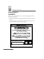
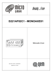
The easy way to install TWdriver is to run the TWsetup program from the
TWdriver release diskette:
1. Pull down the Windows Program Manager File menu and select the Run
option.
2. Enter d:TWsetup as the command line, where d: is the diskette drive id.
Click OK. The following screen will be displayed:
1-4
Chapter 1: TWDriver Touchscreen Driver for Windows
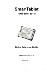
3. Enter the diskette drive id, and click OK.
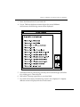
4. If your TWdriver diskette contains drivers for several different
touchscreens, the following screen will be displayed:
5. Scroll the list down, if necessary, to locate your touchscreen type, and select
it by clicking on it. Then click OK.
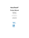
6. Wait while TWsetup copies files to your hard disk.
7. For serial touchscreens, the following screen is now displayed. A slightly
different screen is displayed for bus touchscreens:
1-5
VRC 4000 Software Driver Manual
8. In most cases, you simply have to select COM1 or COM2. For more
advanced hardware configurations, refer to the section ’Hardware
Configuration’. Click OK.
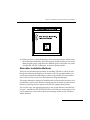
9. Windows only loads device drivers when it starts. The following screen is
displayed. Click OK, then close down Windows and re-start it.
1-6
Chapter 1: TWDriver Touchscreen Driver for Windows
10. When you have re-started Windows, the touchscreen driver will be active
but will require calibration. Start TWsetup by double clicking its icon in the
Main program group, and select the calibrate option. Touch the two points
as requested. See the ’Calibration’ section for further details.
Alternative Installation Methods
There are several alternative methods of installing TWdriver, which are now
briefly described for the benefit of advanced users. We recommend that you
use the easy method described above where at all possible. You may need to
refer to this section if you use a shell other than Program Manager.
The easiest alternative method of installing the touchscreen device driver is to
use the DOS version of the Windows Setup program to install an 'other' mouse
driver, by selecting the last option on the mouse configuration picklist.
You can also copy the appropriate driver to the system directory and edit the
'mouse=' command in the SYSTEM.INI file to load the new mouse driver. You
can determine the correct driver from the oemsetup.ini file on the TWdriver
release diskette.
1-7
VRC 4000 Software Driver Manual
The TWsetup program must be used to perform touchscreen calibration, so
you need to copy the TWSETUP.EXE and BWCC.DLL files onto your hard disk.
It is usually convenient to have TWsetup as an icon in one of the program
groups. In Program Manager groups this is done with the New option of the
File menu. You must specify the command line as 'TWSETUP CONTROL'. If
TWsetup is run without the CONTROL parameter, it starts in 'install' mode.
The TWdriver default configuration settings are chosen to be appropriate in
most cases, although if your touchscreen is connected to a serial port other than
COM1, you will need to alter the hardware configuration as described in
’Hardware Configuration’.
Windows Double Click Speed
Sometimes you cannot achieve double clicks as quickly using a touchscreen as
you can with a mouse, so you may need to adjust Windows' mouse double click
time threshold. This setting controls the length of time during which Windows
will recognize two clicks as a double click as opposed to two separate single
clicks.
An easy way to adjust this setting is to select the 'Main' program group
window, then 'Control Panel', then 'Mouse', and then set the Double Click
Speed to Slow.
The same effect can also be achieved by editing WIN.INI and setting
DoubleClickSpeed=900 in the [Windows] section.
The User Controls section of TWsetup also contains the same
DoubleClickSpeed control.
Windows Border Width
You may wish to increase the Windows' border width in order to make them
easier to touch. To do this, select the 'Main' program group window, then
'Control Panel', then 'Desktop'. Increase the Border Width to approximately 12.
The same effect can also be achieved by editing WIN.INI and setting
BorderWidth=12 in the [Windows] section.
1-8
Chapter 1: TWDriver Touchscreen Driver for Windows
Hardware Installation
For some types of touchscreen, TWdriver has specific requirements for the
controller switch settings, and where specified these must be set accordingly. If
the touchscreen is connected to a serial port other than COM1, or a bus
controller touchscreen is set to a port address or IRQ other than the defaults
given in the ’Switch Settings and Hardware Notes’ section, the TWdriver
hardware configuration settings must match the settings on the hardware
itself. Refer to this section for touchscreen-specific details.
Calibration
Calibration enables the software to accurately align touches with the mouse
cursor. This procedure usually only needs to be performed once, as part of the
initial software installation, and only needs to be repeated if the alignment of
the touchscreen with the visual image should change for any reason, or if the
calibration data file is deleted for any reason. The procedure involves touching
two displayed points, which the software then stores in a file known as the
calibration file.
To perform calibration, run the TWsetup program by double clicking its icon
and select the calibration option. Touch the first point, then the second point,
as requested. Calibration is now complete, and a file called TWcalib will have
been created in the Windows directory.
If you do not have a mouse, you can start the control program using the
keyboard. Use Control-Tab to switch between program group windows and
icons, then use the cursor keys to highlight the TWsetup icon, then Enter to
start it. Once in TWsetup, press Alt-C to run the Calibrate option.
With the touchscreen working and correctly calibrated, touching the screen
should move the mouse cursor immediately to the point of the touch, and the
cursor should follow your finger as you slide it around the screen.
Configuration
A number of configuration options affect the operational characteristics of the
touchscreen, and enable you to tailor it to your precise needs. All the
configuration options can be established or amended using the supplied
control program, TWsetup.
1-9
VRC 4000 Software Driver Manual
Most of the options are to be found in the 'User Controls' section of the
program:
1-10
Chapter 1: TWDriver Touchscreen Driver for Windows
Whenever you make any changes to the configuration, you can press the
'Activate new settings' button to bring your changes into immediate effect, and
press the 'Test' button to test how the button responds to touches. Pressing the
'OK' button activates your changes, saves them, and exits the User Controls
screen. Pressing the 'Cancel' button cancels any changes you have made, and
exits the User Controls screen.
Button Modes - Pre-Defined
The method used to simulate button presses and releases depends on the
Button Mode configured. The default after initial installation is Button Mode
three (Time/Tap mode).
There are six pre-defined modes, which are quick and easy to configure, and
four 'User Defined' modes which offer great flexibility, but require slightly
more setting up.
The pre-defined modes operate as follows:
Button Mode 1 - Touchdown mode
The mouse cursor is moved to the point of the touch, then the button is
immediately pressed. You can then slide around with the button held down.
The button is released when you remove your finger from the screen.
Button Mode 2 - Time mode
The mouse cursor is moved to the point of the touch, but the button is not
pressed. You can then slide around with the button not pressed. Any time you
hold your finger stationary for about half a second, the button is pressed, and
a beep sounds. Once pressed, you can slide around with the button pressed,
and the button is only released when you remove your finger from the screen.
Button Mode 3 - Time/Tap mode
Mode 3 is similar to mode 2, but double clicks are possible. After holding
stationary to generate a button press, you quickly lift your finger off the screen
and then immediately touch it again. A second button press is generated
immediately at the same location as the first one, and another beep sounds.
1-11
VRC 4000 Software Driver Manual
Button Mode 4 - Tap mode
The mouse cursor is moved to the point of the touch, but the button is not
pressed. Button presses are generated by quickly lifting your finger off the
screen and then touching it again within a short time. Double clicks are
achieved by doing this twice.
Button Mode 5 - Time/Time mode
Mode 5 is similar to mode 3, except the second press is achieved by holding
your finger stationary for a further half second after the first beep.
Button Mode 6 - Liftoff mode
The mouse cursor is moved to the point of the touch, but the button is not
pressed. When you lift your finger off the screen, the button is pressed and then
immediately released again. Double clicks can be achieved by quickly touching
the screen and lifting off again.
Button Modes - User-Defined
TWsetup allows you to define, save and recall up to four User Defined Button
Modes, each with their own characteristics and behavior. These Button Modes
allow you to specify the touch triggers which cause simulated mouse button
events in a very flexible and powerful way.
1-12
Chapter 1: TWDriver Touchscreen Driver for Windows
Initially, the four User Defined Button Modes are undefined. To define one, you
select one, and press the 'Edit Mode' button. This displays the 'Set User Defined
Mode' screen.
You must now define the touch triggers which cause each of six possible button
events. The six button events are:
1. Down1
The first mouse button press
2. Up1
The first mouse button release
3. Down2
The second mouse button press (for double clicks)
1-13
VRC 4000 Software Driver Manual
4. Up2
The second mouse button release
5. Down3
Subsequent mouse button presses
6. Up3
Subsequent mouse button releases
Down1 defines the touch triggers required to simulate a first button press, and
Up1 defines the touch event required to simulate releasing the button.
Down2 and Up2 define the touch trigger, if any, which will simulate another
button press, if that trigger occurs within the time specified by the ClickTime
option, in other words the actions required to generate a double click.
Down3 and Up3 define the touch trigger, if any, which will simulate
subsequent button presses.
The description of ClickTime, later in this section, further describes the
significance of first, second and subsequent clicks.
The touch triggers which can be assigned to each of the six mouse events are:
1. None
ie The mouse event will never occur
2. Immediate
ie The mouse event will occur immediately
3. Touchdown
ie The mouse event will occur on touchdown
4. Liftoff
ie The mouse event will occur on liftoff
5. Time
ie The mouse event will occur on stationary touch
6. Tap
ie The mouse event will occur on tapping the screen
7. Z press
ie The mouse event will occur on increasing pressure
8. Z release
ie The mouse event will occur on decreasing pressure
The None option is used to prevent double clicks or subsequent clicks.
The Immediate option is used to generate the mouse event immediately it
becomes possible.
The Touchdown option is triggered whenever a finger makes initial contact
with the screen.
1-14
Chapter 1: TWDriver Touchscreen Driver for Windows
The Liftoff option is triggered whenever a finger breaks contact with the
screen. A finger lift always causes the mouse button to be released if it is
pressed.
The Time option is triggered by holding a touch stationary for an amount of
time defined by the ClickTime option, which is described later in this section.
A Tap is defined as a finger lift followed by a re-touch within the amount of
time also defined by ClickTime. Note that a click generated by a tap will occur
at the point of the liftoff, not at the point of the re-touch.
The Z options are only supported on touchscreens with a Z (pressure) axis.
To assign a touch trigger to a mouse event, select the button event in the left
hand column, then the touch trigger you want to assign to it from the right
hand column. The centre column shows the trigger currently assigned to each
button event. As a bare minimum, you need to assign triggers to the Down1
and Up1 events. Press the 'Activate new Button Mode' button to immediately
activate the new mode, and press the 'Test' button to test how the button
responds to touches. Press the 'OK' button to activate your changes, save them,
and exit back to the User Controls screen. Press the 'Cancel' button to cancel
any changes you have made, and exit to the User Controls screen.
The use of User Defined Button Modes is best explained by examples. In the
notation that follows, a Button Mode is defined by specifying the six button
events Down1, Up1, Down2, Up2, Down3, Up3.
The pre-defined Button Modes 1 to 6 are defined as follows:
1. Mode 1: Touchdown, liftoff, touchdown, liftoff, touchdown, liftoff.
2. Mode 2: Time, liftoff, none, none, none, none.
3. Mode 3: Time, liftoff, tap, liftoff, none, none.
4. Mode 4: Tap, liftoff, tap, liftoff, tap, liftoff.
5. Mode 5: Time, time, immediate, liftoff, none, none.
6. Mode 6: Liftoff, immediate, liftoff, immediate, liftoff, immediate
The following examples give an idea of the many other modes which can be
created:
1-15
VRC 4000 Software Driver Manual
• Touchdown, immediate, none, none, none, none.
This will generate an instantaneous single click (down and up) when the
screen is touched. It will not be possible to drag the mouse cursor with
the button pressed.
• Touchdown, immediate, immediate, immediate, none, none.
This will generate two instantaneous clicks (down, up, down, up) when
the screen is touched. It will not be possible to drag the mouse cursor
with the button pressed.
• Time, immediate, immediate, liftoff, none, none.
This will generate a double click when a touch is held stationary for
ClickTime, and the button will remain down until the finger is lifted off
the screen, so it will be possible to drag the cursor with the button down.
• Liftoff, immediate, tap, liftoff, none, none.
This will generate a single click (down and up) when the finger is lifted
off the screen, and a second click if the screen is re-touched within
ClickTime. Then the button will remain down until the finger is again
lifted off the screen.
• Time, time, immediate, time, immediate, time.
This will generate a continuous sequence of button presses as long as the
finger is held stationary.
• Zpress, Zrelease, Zpress, liftoff, none, none.
This will allow you to move the cursor around, then press hard to
generate a button press, and release it by reducing the pressure. Double
clicks will be possible by pressing hard again.
• Touchdown, immediate, immediate, immediate, immediate.
Not recommended! Continuous, never ending, button presses will be
generated on first touching the screen. In fact TWdriver will go into a
tight loop continuously pressing and releasing the button, and no other
processing will be able to occur.
1-16
Chapter 1: TWDriver Touchscreen Driver for Windows
Touch Offset
Normally, the cursor is directly underneath your finger, which is desirable in
most circumstances, but inconvenient in others. With Touch Offset On, the
cursor is offset directly above your finger by 10% of the height of the screen,
except at the top and bottom, where it converges with your finger as you
approach the edge. This can be very useful in applications where you need to
be able to see the precise position of the cursor clearly.
Button
Normally, the left button is simulated, although a configuration option allows
the right button, or both buttons at once, to be simulated instead.
ClickTime
ClickTime is a time interval which TWdriver uses for a number of purposes. It
is defined as a number of system clock ticks, there being 18.2 ticks to each
second. The default value of ClickTime is 9, which corresponds to about half a
second. Smaller values correspond to a shorter time, and larger values
correspond to a longer time.
ClickTime has three functions:
A Time touch event is generated by holding your finger stationary in contact
with the screen for ClickTime. So in Button Mode 2 (Time mode), for example,
ClickTime controls the length of time you need to hold your finger stationary
for to generate a button press.
A Tap touch event is defined as a finger lift and re-touch within ClickTime. So
in mode 4 (Tap mode), for example, ClickTime defines the length of time within
which you must re-touch the screen after lifting off in order to generate a
button press.
1-17
VRC 4000 Software Driver Manual
ClickTime is also used to distinguish between first, second, and subsequent
clicks, allowing each to be assigned to different types of touch event. For
example, after the first click has been generated in Button Mode 3 (Time/Tap
mode), TWdriver is expecting a tap event to generate a second click, but only
if it occurs within ClickTime. After ClickTime, a tap will be ignored since
TWdriver will then be expecting a first press again, and will only respond to a
time event. Similarly, after a second click and within ClickTime, TWdriver will
be expecting the event defined for a subsequent button press, if any. After
ClickTime, it will again start looking for the event defined for a first button
press.
Note that second button presses - the second click of a double click, are forced
by TWdriver to occur at exactly the same location as the first click. This has an
interesting, and sometimes confusing, implication in Button Mode 1
(Touchdown mode). In an application such as the Windows calculator,
Touchdown mode is ideal for simulating the buttons of a real calculator.
However, two successive clicks on two different buttons within ClickTime
would be treated by TWdriver as a double click on the first button, which is
incorrect in this situation. The solution here is to reduce ClickTime to, say, 1,
since it serves no purpose in this case.
DoubleClickSpeed
This option actually belongs to the Windows mouse control panel, but is
duplicated here for convenience. It changes the speed at which Windows will
register a double click. For touchscreens, this normally needs to be set to the
high end of the scale.
Sensitivity
The Sensitivity option specifies the time interval required to register a finger
lift, and uses the same units as the ClickTime option. The default varies
depending on the touchscreen model, but is the smallest value required to
make the touchscreen usable, typically 1, 2, or 3. In some cases you may wish
to increase this time, so that any momentary loss of contact when sliding
around is ignored.
1-18
Chapter 1: TWDriver Touchscreen Driver for Windows
Stabilization
The Stabilization option sets the number of touch coordinates from the
hardware which are averaged to produce stabilized values. The default varies
depending on the touchscreen model, but is commonly 0, ie no stabilization, 2,
or 3. This value may be increased if the cursor appears jittery. Specifying a
higher than necessary value causes the cursor to be unnecessarily delayed in
following your finger around the screen.
Sound
The Sound on/off option enables or disables the beep which accompanies
simulated button presses.
1-19
VRC 4000 Software Driver Manual
Hardware Configuration
Selecting the 'Hardware Controls' option of TWsetup displays the Hardware
Controls screen:
These options control the configuration of the software to work with the
touchscreen hardware, and must be set correctly for your hardware
configuration or the touchscreen will not work.
1-20
Chapter 1: TWDriver Touchscreen Driver for Windows
Standard COM Port Configurations
In most cases, the touchscreen will be connected to either a standard COM1
port or a standard COM2 port. In these cases, all that is required is to select the
appropriate port. The correct port address and IRQ will be assigned
automatically.
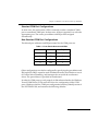
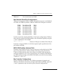
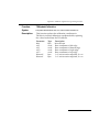
Non-Standard COM Port Configurations
The default port addresses and IRQs assumed for the COM ports are:
Table 1-1. Com Port Addresses and IRQs
ComPort
Address
IRQ
1
3F8
4
2
2F8
3
3
3E8
5
4
2E8
2
Other configurations can also be configured by specifying the port address and
IRQ explicitly. IRQ 2 cannot be used in Enhanced mode, since Windows uses it
for vertical retrace handling, and interrupts do not reach the touchscreen
driver. The port address is specified in hexadecimal.
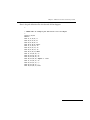
In order for COM ports to work properly in 386 enhanced mode, the Windows
Virtual COM Driver (VCD) must also know the configuration of the COM
ports. Windows takes the COM port configuration from the [386enh] section of
the SYSTEM.INI file, and assumes the following defaults:
1-21
VRC 4000 Software Driver Manual
COM1base=3F8
COM1irq=4
COM2base=2F8
COM2irq=3
COM3base=2E8
COM3irq=4
COM4base=2E0
COM4irq=3
The defaults for COM1 and COM2 do not normally require overriding, but the
defaults for COM3 and COM4 usually do. When you use TWsetup to select a
non-standard COM port configuration, TWsetup updates SYSTEM.INI for
you.
However, in order to handle the port correctly in 386 enhanced mode,
Windows also needs to find the port address listed in the BIOS COM port table.
In many cases, non-standard COM ports will not be detected by the system
BIOS at boot time, so the port address will not be automatically listed in the
BIOS COM port table. A small DOS utility, TBbios, is provided with TWdriver,
to force port addresses into the BIOS COM port table, and this should be run in
your AUTOEXEC.BAT file. For example, “TBbios 3 3E8” will force the port
address 3E8 into the entry for COM3 in the BIOS COM port table. TWsetup
does not amend your AUTOEXEC.BAT file for you.
1-22
Chapter 1: TWDriver Touchscreen Driver for Windows
Automatic Re-initialization
Some touchscreen controllers require a software initialization sequence to set
them into the required operating mode, and TWdriver always performs this
when Windows loads. When the controller is serially connected and external to
the PC, there is always the possibility that the user will power the touchscreen
controller off and on, particularly if the controller is located inside the monitor.
The controller will then power up uninitialized and will not work. TWdriver
attempts to detect this situation and automatically re-initialize the controller
when required. Automatic re-initialization is triggered by a positive going
change in the state of the CTS signal on the RS232 interface. Note, however, that
if the CTS connection is omitted from the RS232 cable the touchscreen will still
work, but the automatic re-initialization function can not, and in some cases
will be falsely triggered by the floating CTS. While TWdriver is attempting to
re-initialize the touchscreen, it can cause the computer to slow down
considerably. Automatic re-initialized can be disabled here if required.
Communications Parameters
TWdriver chooses defaults for Baud Rate, Parity, Databits and Stopbits which
are either the only ones supported by the touchscreen, or which will be
automatically recognized by the touchscreen, or which can be used with the
switch settings defined in the ’Switch Settings and Hardware Notes’ section.
You may wish to change the communications parameters to support different
switch settings, or to reduce the communications overhead.
Shared IRQ's and Global Rearming
For serial touchscreens only, TWdriver supports the ability for more than one
COM port to share the same IRQ. For hardware reasons, this only works when
the hardware is designed to support IRQ sharing, for example on multiport
serial adapter cards. IRQ sharing cannot be made to work by simply switching
two ordinary COM ports to the same IRQ.
The Global Rearm IRQ-sharing mechanism found on an increasing number of
machines is also supported.
1-23
VRC 4000 Software Driver Manual
Bus Touchscreens
A different Hardware Controls screen is displayed for touchscreen controllers
which plug directly into the PC bus. In these cases, only the port address and
IRQ need be specified if the jumper or switch settings do not match the defaults
given in the ’Switch Settings and Hardware Notes’ section.
Activating the New Configuration
Press 'OK' to save the changes and exit, or 'Cancel' to cancel your changes and
exit. Changes to the hardware configuration cannot be activated immediately.
You must restart Windows for them to take effect.
WIN.INI
All the TWdriver configuration options are stored in the Windows
configuration file WIN.INI, and you may alter the TWdriver configuration by
editing this file using a text editor. The syntax of the entries follows. All entries
are shown with their default values, followed by the valid range of values:
[Touch-Base]
ButtonMode=3
ButtonDown1=0
ButtonUp1=0
ButtonDown2=0
ButtonUp2=0
ButtonDown3=0
ButtonUp3=0
ClickTime=9
Sensitivity=1
Stabilisation=0
Offset=Off
Button=Left
Sound=On
ComPort=1
Address=3F8
Interrupt=4
Baud=9600
Parity=N
1-24
0-6
0,1,2,4,8,16,32,64
0,1,2,4,8,16,32,64
0,1,2,4,8,16,32,64
0,1,2,4,8,16,32,64
0,1,2,4,8,16,32,64
0,1,2,4,8,16,32,64
1 - 20
1 - 20
0 - 20
On, Off
Left, Right, Both
On, Off
1, 2, 3, 4
0 - FFFF
1 - 15
1200,2400,4800,9600
N, O, E
Chapter 1: TWDriver Touchscreen Driver for Windows
DataBits=8
StopBits=1
IRQshare=Off
IRQreArm=Off
AutoReInit=On
Path=.
PacketsToIgnore=0
7, 8
1, 2
On, Off
On, Off
On, Off
A DOS directory pathname
1 - 20
UserMode1=n n n n n n
UserMode2=n n n n n n
UserMode3=n n n n n n
UserMode4=n n n n n n
CurrentUserMode=n
0,1,2,4,8,16,32,64 (x6)
0,1,2,4,8,16,32,64 (x6)
0,1,2,4,8,16,32,64 (x6)
0,1,2,4,8,16,32,64 (x6)
1-4
ButtonDown1 - ButtonUp3 are only processed if ButtonMode is 0.
Path specifies the pathname of the calibration file. If this option is not used, the
TWcalib file will reside in the Windows directory. This option may be used to
locate it elsewhere.
PacketsToIgnore specifies a number of coordinate packets to ignore before
sensing a touchdown. The default value is zero. This can be useful in
touchdown mode, where the touchdown position is the position of the button
click. If the touchscreen takes a few packets to stabilize on the correct position,
this parameter can be used to ignore the first few inaccurate packets. This
feature is not supported by the configuration control program.
The touch triggers for the User Defined Button Modes are defined by numbers,
as follows:
0
None
ie The mouse event will never occur
1
Immediate
ie The mouse event will occur immediately
2
Touchdown
ie The mouse event will occur on touchdown
4
Liftoff
ie The mouse event will occur on liftoff
1-25
VRC 4000 Software Driver Manual
8
Time
ie The mouse event will occur on stationary
touch
16
Tap
ie The mouse event will occur on tapping the
screen
32
Z press
ie The mouse event will occur on increasing
pressure
64
Z release
ie The mouse event will occur on decreasing
pressure
An even further range of possibilities is available here than in the control
program: Touch events can be OR'ed by adding their configuration numbers
together. So, for example, the value 24 would define a trigger of Time OR Tap.
The default BaudRate, Parity, DataBits and StopBits are touchscreen
dependent. IRQshare and IRQreArm are mutually exclusive. That is, they
should not both be On.
Co-existence with Mice
TWdriver operates with a touchscreen alone if no mouse hardware is present,
or with a mouse alone if no touchscreen is present, or with both together if both
are present.
TWdriver supports all types of Microsoft and IBM PS/2 mice, and 100%
hardware compatibles. However, since Windows can only load one mouse
driver at a time, it is not possible to provide simultaneous support for mice
which require their own special Windows driver.
Co-existence with DOS TBdriver
In Windows Real and Standard modes, TBdriver (and TBmouse, if required)
may be left resident while Windows runs if desired. They will be disabled
while Windows is running, but restored to operation when Windows
terminates or executes a Dos shell.
1-26
Chapter 1: TWDriver Touchscreen Driver for Windows
However, in Windows Enhanced mode, each virtual machine is a perfect copy
of the machine environment which Windows finds when it starts up, including
any TSR's. Windows continues to reflect serial interrupts into TBdriver, as well
as TWdriver, with the result that the Windows driver loses data and
performance of the touchscreen is severely degraded. For this reason, TBdriver
must not be loaded when Windows is started in Enhanced mode.
Troubleshooting and Technical Support
The control program 'TWsetup' displays an 'About' box which amongst other
things, shows the initialization status and whether calibration is valid for the
installed TWdriver.
If the initialization status is anything other than 'Ok' read on... if the calibration
status is anything other than 'Ok', this represents the DOS error encountered
when TWdriver attempted to access the calibration data - try re-calibrating. If
the communications errors are anything other than zero read on....
In case of difficulty, the following checks should be made before calling
technical support:
No cursor movement when touchscreen touched
• Check that the touchscreen has power, and that its communication cable
is connected to the computer.
• Check that the switch settings, if any, are set as specified in ’Switch
Settings and Hardware Notes’.
• Check that you selected the correct driver for your touchscreen in the
Windows Setup program.
• Check that the TWdriver hardware configuration is set up correctly. For
serial touchscreens check that TWdriver is configured for the correct
serial port number. For COM3, COM4, and bus controller touchscreens,
check that the port address and IRQ are configured to match the
hardware switch or jumper settings. Also check for port address or IRQ
conflicts with other cards in the system.
Cursor moves but incorrectly
• Check that you have calibrated, and that TWdriver still has access to the
1-27
VRC 4000 Software Driver Manual
TWcalib calibration file, either in the Windows directory, or via the Path
setting in WIN.INI.
• If you have re-installed TWdriver for a different type of touchscreen, you
will need to re-calibrate.
Difficulties with double clicks
• Ensure that Windows' mouse double click speed is set to slow, as
described in the ’Getting Started’ section.
• You may have set the TWdriver settings for ClickTime or Sensitivity to
time intervals so great that two clicks take longer than the time allowed
by the Windows DoubleClickSpeed setting. If you have set high values
for ClickTime or Sensitivity, try reducing them.
System performance
• If your touchscreen requires software initialization, and is powered off,
TWdriver will attempt to re-initialize it every ten seconds, which may
degrade system performance. This can be prevented by specifying
AutoReInit=Off in WIN.INI, or using the TWsetup program.
• If you are running Windows in 386 enhanced mode, and you left a DOS
touchscreen driver running when you started Windows, Windows will
reflect serial interrupts into that as well as TWdriver, which will severely
degrade touch responses.
TBdiag - The Touchscreen Diagnostic Program
The TBdiag program is provided on the distribution diskette for the more
technically minded user, to help identify communication problems with serial
touchscreens, or simply to observe the raw data from the touchscreen. TBdiag
is a DOS program, and is invoked from the DOS command line by typing
TBdiag.
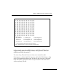
Its monitor screen shows data sent to and received from the touchscreen,
allowing you to see if it is responding to the initialization sequence, and if it is
sending any coordinate data at all. You can re-try the initialization sequence at
any time by pressing 'I', switch to hex display mode by pressing 'H', and exit
by pressing 'X'. TBdiag takes several optional parameters:
1-28
Chapter 1: TWDriver Touchscreen Driver for Windows
The TBdiag Command Line
TBdiag [Port] [/C:bbbb,p,d,s] [/A:address] [/I:irq] [/NI] [/G]
Port
/C:bbbb,p,d,s
bbbb
p
d
s
/A:address
/I:irq
/NI
/G
Specifies a serial port (1 .. 8)
Communications parameters:
Baud rate (1200, 2400, 4800, 9600)
Parity (N, O, E)
Databits (7, 8)
Stopbits (1, 2)
Port address (hexadecimal)
Interrupt request number (0 .. 15)
No initialization. Do not initialize touchscreen.
Perform Global rearming
TBdiag /?
Prints the above summary
Most of these options are only rarely required. In most cases all that is required
is simply:
TBdiag 1
TBdiag 2
For a touchscreen on COM1, or:
For a touchscreen on COM2.
Example
TBdiag /C:4800,e,7,2 /A:748 /I:10 /NI
Load TBdiag on a COM port at address 748 hex, using irq 10, at 4800 baud, even
parity, 7 data bits, 2 stop bits. Do not perform touchscreen initialization.
A large window shows data sent to and received from the touchscreen, while
the lower window shows the status, mainly of the serial port.
Interpretation of much of the information given by TBdiag requires specialist
knowledge of serial ports and the touchscreen data stream. However, a
working touchscreen should always show a data stream of some kind when
touched.
1-29
VRC 4000 Software Driver Manual
Before Calling Technical Support
Please have the following information available (most can be found in
TWsetup's 'About' box) before calling Technical Support:
• TWdriver version number
• Touchscreen manufacturer and type
• Touchscreen communications hardware configuration
• Windows version number, and modes affected
• DOS manufacturer and version number
Please also have the TWdriver distribution diskette to hand, as we may ask you
to load and run TBdiag.
1-30
Chapter 1: TWDriver Touchscreen Driver for Windows
Service Information
If you have a problem with your equipment, contact the Symbol Support Center.
Call the Support Center from a phone near the equipment so that the service person
can try to talk you through your problem.
If your problem cannot be solved over the phone, you may need to return your
equipment for servicing. If that is necessary, you will be given specific directions.
Note:
Symbol Technologies is not responsible for any damages
incurred during shipment if the approved shipping container
is not used. Shipping the units improperly can possibly void
the warranty. If the original shipping container was not kept,
contact Symbol to have another sent to you.
Symbol Support Center
For service information, warranty information or technical assistance, call:
USA
SYMBOL SUPPORT CENTER
1-800-653-5350
Canada
Mississauga, Ontario
Canadian Headquarters
(905) 629-7226
Europe
Wokingham, England
European Headquarters
0734-771-222 (Inside UK)
+44-1734-771222 (Outside UK)
1-31
VRC 4000 Software Driver Manual
Asia
Singapore
Symbol Technologies Asia, Inc.
337-6588 (Inside Singapore)
+65-337-6588 (Outside Singapore)
If you purchased your Symbol product from a Symbol Business Partner, contact that
Business Partner for service.
1-32
Chapter 2 TBDriver Touchscreen
Driver for DOS
Contents
Introduction . . . . . . . . . . . . . . . . . . . . . . . . . . . . . . . . . . . . . . . . . . . . . . . . . . . . . . . . . . . . . . . . . . . . . 2-3
Getting Started . . . . . . . . . . . . . . . . . . . . . . . . . . . . . . . . . . . . . . . . . . . . . . . . . . . . . . . . . . . . . . . . . . . 2-5
Concepts . . . . . . . . . . . . . . . . . . . . . . . . . . . . . . . . . . . . . . . . . . . . . . . . . . . . . . . . . . . . . . . . . . . . . . . . 2-8
Application Programming Interface . . . . . . . . . . . . . . . . . . . . . . . . . . . . . . . . . . . . . . . . . . . . 2-8
Touch Input Data . . . . . . . . . . . . . . . . . . . . . . . . . . . . . . . . . . . . . . . . . . . . . . . . . . . . . . . . . . . . 2-8
Application Programming Interface . . . . . . . . . . . . . . . . . . . . . . . . . . . . . . . . . . . . . . . . . . . . . . . 2-17
Before Calling The API . . . . . . . . . . . . . . . . . . . . . . . . . . . . . . . . . . . . . . . . . . . . . . . . . . . . . . . 2-17
Loading and Unloading TBDRIVER . . . . . . . . . . . . . . . . . . . . . . . . . . . . . . . . . . . . . . . . . . . . . . . 2-47
The TBdriver Command Line . . . . . . . . . . . . . . . . . . . . . . . . . . . . . . . . . . . . . . . . . . . . . . . . . 2-47
Unloading TBdriver . . . . . . . . . . . . . . . . . . . . . . . . . . . . . . . . . . . . . . . . . . . . . . . . . . . . . . . . . 2-52
TBdriver Messages . . . . . . . . . . . . . . . . . . . . . . . . . . . . . . . . . . . . . . . . . . . . . . . . . . . . . . . . . . . . . . 2-53
TBdriver Return Codes . . . . . . . . . . . . . . . . . . . . . . . . . . . . . . . . . . . . . . . . . . . . . . . . . . . . . . 2-55
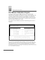
The TBdriver Demonstration Program . . . . . . . . . . . . . . . . . . . . . . . . . . . . . . . . . . . . . . . . . . . . . 2-56
The TBdriver Calibration Program . . . . . . . . . . . . . . . . . . . . . . . . . . . . . . . . . . . . . . . . . . . . . . . . 2-61
Hard Calibrate . . . . . . . . . . . . . . . . . . . . . . . . . . . . . . . . . . . . . . . . . . . . . . . . . . . . . . . . . . . . . . 2-62
Options 1 - 9 . . . . . . . . . . . . . . . . . . . . . . . . . . . . . . . . . . . . . . . . . . . . . . . . . . . . . . . . . . . . . . . . 2-62
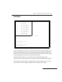
Test Menu . . . . . . . . . . . . . . . . . . . . . . . . . . . . . . . . . . . . . . . . . . . . . . . . . . . . . . . . . . . . . . . . . . 2-64
Customize Video Mode Mappings . . . . . . . . . . . . . . . . . . . . . . . . . . . . . . . . . . . . . . . . . . . . 2-65
Troubleshooting and Technical Support . . . . . . . . . . . . . . . . . . . . . . . . . . . . . . . . . . . . . . . . . . . . 2-68
TBDIAG - The Touchscreen Diagnostic Program . . . . . . . . . . . . . . . . . . . . . . . . . . . . . . . . . . . . 2-69
The TBdiag Command Line . . . . . . . . . . . . . . . . . . . . . . . . . . . . . . . . . . . . . . . . . . . . . . . . . . 2-69
How To Contact Technical Support . . . . . . . . . . . . . . . . . . . . . . . . . . . . . . . . . . . . . . . . . . . . 2-71
TBMOUSE - The Mouse Emulator . . . . . . . . . . . . . . . . . . . . . . . . . . . . . . . . . . . . . . . . . . . . . . . . . 2-72
The TBmouse Command Line . . . . . . . . . . . . . . . . . . . . . . . . . . . . . . . . . . . . . . . . . . . . . . . . 2-73
Button Emulation Modes . . . . . . . . . . . . . . . . . . . . . . . . . . . . . . . . . . . . . . . . . . . . . . . . . . . . . 2-74
The Mouse Cursor . . . . . . . . . . . . . . . . . . . . . . . . . . . . . . . . . . . . . . . . . . . . . . . . . . . . . . . . . . 2-74
Absolute Mode . . . . . . . . . . . . . . . . . . . . . . . . . . . . . . . . . . . . . . . . . . . . . . . . . . . . . . . . . . . . . 2-75
Relative Mode . . . . . . . . . . . . . . . . . . . . . . . . . . . . . . . . . . . . . . . . . . . . . . . . . . . . . . . . . . . . . . 2-75
The Mickey to Pixel Ratio . . . . . . . . . . . . . . . . . . . . . . . . . . . . . . . . . . . . . . . . . . . . . . . . . . . . 2-75
Initial Virtual Screen Size . . . . . . . . . . . . . . . . . . . . . . . . . . . . . . . . . . . . . . . . . . . . . . . . . . . . . 2-77
Initial cursor position . . . . . . . . . . . . . . . . . . . . . . . . . . . . . . . . . . . . . . . . . . . . . . . . . . . . . . . . 2-77
Incremental Motion . . . . . . . . . . . . . . . . . . . . . . . . . . . . . . . . . . . . . . . . . . . . . . . . . . . . . . . . . 2-77
Alternate Interpretation of x,y Limits . . . . . . . . . . . . . . . . . . . . . . . . . . . . . . . . . . . . . . . . . . 2-78
2-1
VRC 4000 Software Driver Manual
Ignoring Touches Outside x,y Limits . . . . . . . . . . . . . . . . . . . . . . . . . . . . . . . . . . . . . . . . . . .
Stack Switching . . . . . . . . . . . . . . . . . . . . . . . . . . . . . . . . . . . . . . . . . . . . . . . . . . . . . . . . . . . . .
The Z Axis . . . . . . . . . . . . . . . . . . . . . . . . . . . . . . . . . . . . . . . . . . . . . . . . . . . . . . . . . . . . . . . . .
Acceleration and Other Problems . . . . . . . . . . . . . . . . . . . . . . . . . . . . . . . . . . . . . . . . . . . . .
Unloading TBmouse . . . . . . . . . . . . . . . . . . . . . . . . . . . . . . . . . . . . . . . . . . . . . . . . . . . . . . . . .
TBmouse Messages . . . . . . . . . . . . . . . . . . . . . . . . . . . . . . . . . . . . . . . . . . . . . . . . . . . . . . . . . .
Return Codes . . . . . . . . . . . . . . . . . . . . . . . . . . . . . . . . . . . . . . . . . . . . . . . . . . . . . . . . . . . . . . .
TBmouse Extended Application Program Interface . . . . . . . . . . . . . . . . . . . . . . . . . . . . . .
TBmouse Application Support . . . . . . . . . . . . . . . . . . . . . . . . . . . . . . . . . . . . . . . . . . . . . . . .
TBPAD - The Keyboard Emulator . . . . . . . . . . . . . . . . . . . . . . . . . . . . . . . . . . . . . . . . . . . . . . . . .
The TBpad Demonstration . . . . . . . . . . . . . . . . . . . . . . . . . . . . . . . . . . . . . . . . . . . . . . . . . . .
The TBpad Application Programming Interface . . . . . . . . . . . . . . . . . . . . . . . . . . . . . . . . .
2-2
2-78
2-78
2-78
2-78
2-79
2-79
2-81
2-82
2-87
2-88
2-88
2-94
Chapter 2: TBDriver Touchscreen Driver for DOS
Introduction
A touchscreen is one of the most technically sophisticated yet easiest to use
input devices available today. Many different types are available, but the end
result is the same: you touch the visual images you see, and the computer
responds. A touchscreen is a hardware device which is physically attached to
the computer's monitor and can accurately sense the position of a touch.
Traditionally, touchscreens were sold as a purely hardware product, and
applications tended to interface directly with the hardware, sometimes with
unsatisfactory results. Recognizing the disadvantages of this approach, most
manufacturers do now provide drivers with their touchscreens, and virtually
all modern touchscreen applications use a driver of some sort to insulate the
application programmer from the worst of the low level programming. Some
touchscreen drivers are relatively simple data capture and packet
interpretation utilities, and do little to provide real performance, resilience and
flexibility. TBdriver is at the other end of the scale, providing an extensive
range of facilities and a rich Application Programming Interface. TBdriver also
offers an important advantage over any other touchscreen driver. Each of the
growing number of touchscreens on the market uses a different interface
protocol, but TBdriver maps them all to an identical API. An application
written to the TBdriver API will automatically work with any of the
touchscreens TBdriver supports. That gives you, your application, and your
users a valuable edge in today's tough commercial world.
TBdriver takes care of all the complexities of touchscreen initialization,
interrupt handling, touch buffering, calibration, orientation, scaling and more.
It presents all its functions as a logical, fully documented and consistent API,
saving the application programmer a great deal of time and effort.
The major features of TBdriver are summarized below.
• Supports all touchscreens with an identical API
• Low memory overhead (around 6K)
• Written in Assembler and interrupt driven for performance
• Logical touch buffering for touch-ahead capability
• Well defined logical data stream presented to the API
2-3
VRC 4000 Software Driver Manual
• Resolves touches to application defined rectangular 'pads' if required
• Variable off-touch sensitivity
• Optional coordinate stabilization to control jitter
• Variable X, Y, Z scales and origin
• Hard and soft calibration
• Automatic re-calibration on change of video mode
• Application defined and user defined calibrations
• Automatic screen orientation adjustment
• Automatic re-initialization of touchscreen after power off/on
• Time axis - timing of stationary touches
• Applications can poll for touches, or be event driven
• Extensive API, accessible from any programming language
• Configurable API interrupt vector
• Handles COM1 - COM8 or non-standard serial port configurations
• Handles IRQ sharing and 'Global Rearming'
• Takes advantage of buffered serial port chips (16550A)
• Fully configurable communications parameters
• Touchscreen data packet validation protects against errors caused by lost
interrupts and transmission errors
• Unloads from memory by command argument or API call
• Mouse emulation utility for driving DOS mouse applications
• Keyboard emulation utility for driving DOS keyboard applications
• Demonstration and calibration utility programs
• Serial data diagnostic program
• Example application source code in several languages
• Full documentation
• Support and advice from independent experts in touch
Welcome to the world of real touchscreen programming!
2-4
Chapter 2: TBDriver Touchscreen Driver for DOS
Getting Started
TBdriver is intended for use on IBM PC, XT, AT, PS/2 or compatibles running
DOS 2.x or greater. The TBdriver distribution diskette contains the following
files:
• Readme.dvr
The latest information on TBdriver
• Install.exe
Installation program
• TBdriver.lzh
Compressed drivers and utility programs
• Extras.lzh
Compressed paint drawing and prototyping tool
We recommend that you make a backup copy of the distribution diskette as
soon as you receive it. To install the driver, simply insert the diskette and type:
driveid: install
where driveid is the diskette drive id. First, you will be asked to select the type
of touchscreen you are using from a picklist of supported types. You are then
presented with another picklist which allows you to select the pathname of the
directory you wish the software to be installed and the level of installation you
require. The return key toggles the selection on or off. Default installation
options are as follows:
Base directory
C:\TOUCH
Base Directory
Install driver
Yes
TBdriver
Install utilities
Yes
TBdriver Utilities
Install examples
Yes
Example Applications
Install TBpad
Yes
Keyboard Emulation Utility
Professional Touch
Yes
Prototyping Tool
Install TBpaint
Yes
Paint Package
Start Installation
Select the last entry of the picklist to being installation.
2-5
VRC 4000 Software Driver Manual
The following files are installed by a full installation:
Readme.dvr
TBdriver.exe
TBmouse.exe
TBcal.exe
TBddemo.exe
TBdiag.exe
Text file containing additional information
The DOS touchscreen driver program
The DOS mouse emulator
The TBdriver calibration program
The TBdriver demonstration program
The serial data diagnostic program
In subdirectory Examples:
TBdex.pas
TBdex.exe
TBdex2.pas
TBdex3.pas
TBdex.c
TBdex2.c
TBdex.bas
TBdex.cbl
Intr.obj
Intr.doc
Pascal example source program
Compiled Pascal example
Event driven Pascal example
Example of driving two touchscreens
C example source program
Event driven C example
Basic example source program
Cobol example source program
Software interrupt interface for Cobol
Documentation for Intr.obj
In subdirectory TBpad:
TBpad.exe
TBpad.dem
TBkey.exe
Paddemo.bat
The keystroke emulator
Example pad definition file
Utility to identify keyboard scan codes
Batch file to run TBpad demonstration
In subdirectory Protouch:
Protouch.*
Proedit.*
Professional Touch is a touchscreen application
prototyping tool. See the file protouch.doc
TBgrab.exe
TBmousec.exe
*.bgi
*.chr
for full product details.
In subdirectory TBpaint:
2-6
Chapter 2: TBDriver Touchscreen Driver for DOS
TBpaint.exe
TBpaint.doc
*.bgi
*.chr
TBpaint is a touch painting package. See
TBpaint.doc for full product details.
Please read the readme.dvr file as it may contain important information
concerning the software which was not available in time to be included in this
manual.
The ’Hardware Configuration’ section contains full details on loading
TBdriver, but for most purposes you simply type:
TBdriver c
where c is the number of the COM port which the touchscreen is connected to.
You must then hard calibrate the system using TBcal, option H. If you wish,
you can then run TBddemo and explore the features of TBdriver by trying
them.
2-7
VRC 4000 Software Driver Manual
Concepts
Application Programming Interface
TBdriver is a Terminate Stay Resident program. You load it by running it before
your application, and it remains in low memory until you unload it or reboot
the machine. Your application program interfaces to TBdriver by calling a
software interrupt specifying the function code and parameters in the
processor registers. On return from the call, the registers contain the results of
the function. This is a very common type of interface mechanism under DOS,
and most programming languages offer good facilities for using it. The default
software interrupt used is 66 hex, but this can be altered by means of
environment variable TBdint, as described in ’Hardware Configuration’.
Touch Input Data
At the most basic level, a touchscreen application needs to know the horizontal
and vertical position of a finger touching the screen, and this information takes
the form of a pair of X and Y coordinates, where the origin is arbitrarily predefined as the top left hand corner.
Experience soon shows, however, that it is useful to know a little more, such as
the location of the initial point of contact, the final point of contact, or that the
finger is not presently touching. TBdriver handles this by reporting a touch
type with every pair of X and Y coordinates. There are four touch types:
A First touch is reported for the initial point of contact with the screen. Only
one of these is reported for each touch.
A Repeat touch is reported every time the application reads the driver while the
finger remains on the screen. The coordinates associated with the touch may
change, of course, as the finger slides around the screen.
A Last touch is reported for the point at which the finger breaks its contact with
the screen. Again, there can only be one of these for each touch.
A No touch is reported whenever the application reads the driver and the screen
is not being touched. The X,Y coordinates are irrelevant to this type of
response.
2-8
Chapter 2: TBDriver Touchscreen Driver for DOS
One of the TBdriver API calls allows the application to read the touchscreen,
and this operation returns the following data:
• A touch type
• The X coordinate (left to right)
• The Y coordinate (top to bottom)
• The Z coordinate (pressure), if supported by the hardware
• The Time coordinate (see later)
• The Pad number (see later)
• The Raw coordinates
Scales and the Origin
It is useful for the application to be able to define the X and Y scales of the touch
coordinates returned by the driver, for example to match the pixel resolution of
the current graphics mode, or the number of lines and columns in a text mode.
By default, TBdriver uses a scale of 1000 x 1000 and an origin of 0, which means
that the top left hand corner is defined by coordinates 0,0 and the bottom right
hand corner is defined by coordinates 999,999.
One of the TBdriver API calls allows the application to specify the scales and
origin to be used. After this call, all subsequent touch coordinates will
automatically be mapped to the new scales. A text mode application might, for
example, define a scale of 80 x 25 with an origin of 1,1, so that TBdriver returns
the line and column numbers of the character touched. A graphics application
might define a scale of 640 x 350 with an origin of 0,0, in which case the driver
would return the pixel coordinates touched.
Touch Buffering
Just as you sometimes want to 'type ahead' of a program on a keyboard, you
sometimes want to 'touch ahead' of a program on a touch screen. The absence
of this facility can be a source of extreme frustration for an experienced user
who frequently inputs a lot of data.
TBdriver buffers up to 25 touches, after which the buffer wraps around,
overwriting the oldest touch.
2-9
VRC 4000 Software Driver Manual
Touch buffering affects the touch types reported to the application. For
example, it would make no sense to buffer repeat touches, since these are only
relevant when an application is responding to them in real time. Similarly, there
is no point in buffering no touches, since it makes no sense for an application
to do nothing for the time it takes to read the next packet from the buffer.
TBdriver only buffers first and last touches. Repeat and no conditions are only
reported if they exist at the moment the application reads the driver.
The application can remain completely unaware that buffering is taking place.
It simply has to know how to handle all four types of packet, and TBdriver
takes care of the buffering. There are times, of course, when buffered touches
would be meaningless or undesirable, so one of the API calls allows the
application to flush out the touch buffer.
Calibration
A calibration procedure must be carried out to enable the driver to map the
touch coordinate onto the visual image. In order for this to be done accurately
at all times, two types of calibration are needed: hard calibration and soft
calibration.
Hard Calibration
Hard calibration must always be performed on a newly assembled system.
Hard calibration gives TBdriver vital reference information about the
orientation of the touchscreen and the extents of its raw coordinates.
Hard calibration involves touching the bottom left hand corner, followed by
the top right hand corner of the visual image, which gives the system sufficient
information to determine the position of the four edges. TBdriver can also
deduce from these two touches whether the coordinates of either axis need to
be inverted in order to make the origin the top left hand corner. Some
touchscreens are capable of being installed either way up on the monitor face,
and TBdriver is able to compensate for this after hard calibration. After hard
calibration, any touches outside the calibrated edges are assigned the
appropriate edge coordinates.
2-10
Chapter 2: TBDriver Touchscreen Driver for DOS
In an ideal world, such a simple calibration scheme would be all that was
required to ensure that the touch coordinates correctly reflected the position on
the visual image at all times. Unfortunately however, when driven in different
modes, many monitors display images of considerably different size, and/or
in different positions on the CRT. Normally of course this doesn't matter very
much, but it is very inconvenient for a touchscreen user.
Soft Calibration
Imagine a hypothetical application which uses a graphics mode in some parts,
and a text mode in others. Also suppose that your monitor displays graphics
images half an inch smaller than text images, and that you hard calibrated the
touchscreen in graphics mode. Everything works perfectly in graphics mode,
with the program responding to touches exactly as the user expects. However,
when the screen is switched to text mode, things start to go wrong. The
touchscreen system thinks that the edges of the screen are a quarter of an inch
away from where the user sees them, and the program starts responding to
areas a quarter of an inch away from where the user is touching. Fortunately, a
technique called soft calibration comes to the rescue.
Soft calibration is a means of defining different calibrations for different video
modes. Again, two touches are used to define the edges of the image. The
resulting coordinates are used to re-map the raw coordinates to the new edges.
TBdriver provides a number of facilities for managing the different soft
calibrations required in various video modes. Most cases are handled fully
automatically.
Automatic Soft Calibration
The TBcal utility program supplied allows you to soft calibrate in most of the
commonly used video modes, as well as any two other modes of your choice.
The calibration coordinates are stored in a file called TBcalib. TBdriver reads
TBcalib when it loads, and remembers all the soft calibrations stored in it. It
then monitors changes in the current video mode and automatically switches
to the most appropriate soft calibration if it exists in the file. If no calibration is
defined for a particular mode, then the hard calibration is used.
This automatic mode is the default, and can handle virtually all situations. All
you have to do is run TBcal and provide two touches for each mode. TBdriver
does the rest.
2-11
VRC 4000 Software Driver Manual
User Defined Calibrations
The calibration utility program allows you to specify the video modes which
are used to calibrate in the two user defined calibration modes, and also to edit
the mappings of system video modes to calibration modes used by the driver.
This provides a complete solution to the problem of calibration for nonstandard video modes and non-standard video hardware.
API Call Soft Calibration
In order to cater for the unlikely event that an application needs to use more
video modes than are handled by automatic calibration, TBdriver provides a
set of API calls which allow an application to capture its own soft calibrations,
store them, and activate them at any time. A pair of calls return the raw
coordinates of the bottom left and top right corners of the image, based on two
touches. The application can then store these coordinates, and can issue
another call to activate any set of previously stored calibration coordinates. The
application can therefore arrange to capture calibrations for any number of
modes, store them in a file, and activate them when it puts the video system
into those modes. While such user defined calibrations are active, TBdriver's
automatic re-calibration is disabled, since the application is assumed to want
to manage soft calibration itself. Another API call allows the application to deactivate its own soft calibrations, and return to automatic mode.
Calibration Summary
Always use TBcal to perform hard calibration when you first assemble a new
system, and soft calibrate in all the video resolutions you might use. Allow
TBdriver to handle soft calibration automatically unless you have a good
reason for doing otherwise.
Note that the soft calibrated area cannot be larger than the hard calibrated area,
so the hard calibration must be to the extreme edge of the monitor bezel.
2-12
Chapter 2: TBDriver Touchscreen Driver for DOS
Sensitivity
TBdriver allows you to control the amount of time it takes to register that a
finger has been lifted off the screen. A setting of 1 corresponds to the shortest
possible amount of time, which means the lift is recognized immediately,
giving maximum sensitivity. As the sensitivity value is increased, the finger lift
is detected more slowly, decreasing sensitivity. Usually, maximum sensitivity
(1) is used, where areas of the screen are simply being touched, like keys on a
keyboard, in a data-entry type manner.
A touchscreen can offer data entry techniques which a keyboard cannot, in
particular using the ability to sense that a stylus is sliding around on the screen.
For example a graphical picture of a sliding scale can be a rapid way of
scanning through a list of values or items. Pieces of text or graphics can be
dragged around the screen, or lines can be drawn.
When sliding on some types of touchscreen, the user's finger can accidentally
lose contact with the screen, invoking an undesired response from the
application. This problem can be alleviated by the application temporarily
reducing sensitivity, say to a value of 3. This will cause finger lifts of very short
duration to go undetected, while intentional finger lifts will still be detected
reasonably quickly.
Pads
It is very common to want to match incoming touch coordinates to rectangles
or other shapes displayed on the screen. For example, a touch menu screen
might consist of a number of boxes inviting the user to touch one of the options.
The menu program would then have to determine, from the X and Y
coordinates and the current scale, which box had been touched and act
accordingly. This can easily be done by the application, but it is easier and more
efficient to have TBdriver do it.
2-13
VRC 4000 Software Driver Manual
An API call allows you to define the coordinates of up to 99 rectangular areas
on the screen, and subsequently refer to these areas, or pads, by number. Once
defined, pads can be activated and de-activated. That is, they can be made
touch sensitive, or not touch sensitive. When you read the driver, you always
receive a touch type and a pair of X and Y coordinates. In addition, if the
coordinates fall within the bounds of a currently active pad, you also receive
the pad number in one of the other registers. If the coordinates do not fall
within the bounds of an active pad, you receive a pad number of zero.
So in our menu example above, you would define the option 1 box as pad 1,
option 2 as pad 2, and so on, and then activate all or some of the pads. Then you
read TBdriver and examine the pad number. If it is zero you might just make
a rude noise and try again, but if it is non-zero, you just execute that particular
option.
There is nothing to stop two active pads from having coordinates which
overlap each other on the screen. If a touch falls inside the bounds of more than
one active pad definition, TBdriver assigns the lowest numbered active pad
number to the touch. Overlapped pads will occur in, for example, applications
which make use of popup windows. The simplest way of handling this from a
pad point of view is to de-activate pads which are partially or fully obscured.
If you must leave overlapped pads active, you will have to assign pad numbers
carefully. Pads are numbered 1 to 99, and their coordinates are defined in the
current scale.
Stability
On some touchscreens, if you keep your finger stationary in contact with the
screen, the reported coordinates are subject to continual slight variations,
known as 'jitter'. In certain types of application, you may need to dampen this
effect in order to provide a more stable visual response. An API call allows you
to specify a number of coordinates which are historically averaged to dampen
the effect of these slight variations. The penalty for setting this value high is of
course that it takes longer for movements to be reported, since stabilized
coordinates are affected by the values of a number of previous coordinates.
2-14
Chapter 2: TBDriver Touchscreen Driver for DOS
Stabilization is not implemented for infra-red touchscreens, which never suffer
from jitter.
The Time Axis
TBdriver internally monitors the length of time that your finger remains
stationary in contact with the screen, and returns it with the X, Y and Z
coordinates. The Time axis adds a useful extra dimension to touch screen
programming. While your finger slides around on the screen, the time axis is
zero, or a small value. As soon as you hold your finger stationary, the Time axis
begins to increase, at the rate of one unit per clock tick (the clock ticks 18.2 times
per second). The Time axis can be used, for example, to perform some special
action when the user's finger has remained stationary on a pad for a period of
time.
Event Driven Applications
TBdriver allows your application to drive the touchscreen in two ways. You
can 'poll' the driver to read the touch state through the Read Touches API call,
or you can set TBdriver to interrupt you when a touch event occurs. This is
done by giving TBdriver the address of a 'User Interrupt Service Routine' - a
procedure within your application which will be called when an event occurs.
An event is defined as:
• The touch buffer is not empty
• A Repeat touch and either the X or Y coordinates have changed, i.e. the
finger is sliding around.
• A Repeat touch and the Z axis threshold is crossed by the rising Z
coordinate.
• A Repeat touch and the Time axis threshold is crossed by the rising Time
coordinate.
TBdriver handles all the tricky bits of this for you by saving all the CPU
registers, swapping stacks to one provided by the application, and setting up
the data segment register to point to your data space. TBdriver continues to
operate normally, for example buffering touches, while the User Interrupt
Service Routine executes.
2-15
VRC 4000 Software Driver Manual
Application Programming Interface
Before Calling The API
Before you make any calls to TBdriver, you must make sure that it is loaded.
One very simple check you can make is to examine the address in the chosen
interrupt vector. If it is zero, then TBdriver is definitely not loaded, and if you
were to call this null interrupt, you would certainly crash the machine. If the
address is non-zero, you can be sure that some API is loaded, although you
can't be sure it is TBdriver. Usually your system will be set up such that this
simple check will be quite adequate, but to be really certain, you can check the
8 bytes preceding the address pointed to by the interrupt vector. If it is truly
TBdriver, then these 8 bytes will contain the string 'TBDRIVER'.
The default API interrupt vector is 66 hex, but if some other API in your system
is already using this, you may change it as described in ’Hardware
Configuration’. In this case your application should call the new vector.
TBdriver saves the DS register on entry to the API and restores it on exit. All
other registers are destroyed.
2-16
Chapter 2: TBDriver Touchscreen Driver for DOS
Function:
Activate Pad
Calling Sequence:
AL=13 hex
AH=Pad number
Call API interrupt
Return Values:
None
Description:
Makes a pad touch sensitive. Subsequent touches
within the pad are reported as such. There is no
harm in activating an already active pad, but it
makes no sense to activate a pad which has not yet
been defined.
See Also:
De-activate Pad
Define Pad
Get Pad Definition
2-17
VRC 4000 Software Driver Manual
Function:
Activate Soft Calibration Coordinates
Calling Sequence:
AL =9
BX=X1 (Left edge)
CX=Y1 (Bottom edge)
DX=X2 (Right edge)
ES=Y2 (Top edge)
Call API interrupt
Return Values:
None
Description:
Activates soft calibration for the area defined.
Subsequent coordinates are relative to this new
area. The coordinates must have been
obtained using the Read Soft Calibration
Coordinates function.
Note that while such API call soft calibration is
active, TBdriver's normal function of
automatically loading soft calibrations
appropriate to the current video mode is
disabled.
For most purposes, the usage of this call has
been superseded by the Soft Calibrate API call.
See Also:
2-18
Read Soft Calibration Coordinates
De-activate Soft Calibration
Get Current Calibration
Chapter 2: TBDriver Touchscreen Driver for DOS
Function:
Calling Sequence:
De-Activate Soft Calibration
Return Values:
None
Description:
De-activates the soft calibration which was defined
using the Activate Soft Calibration Coordinates
function. Automatic calibration is resumed.
AL =10 hex
Call API interrupt
For most purposes, the usage of this call has been
superseded by the Soft Calibrate API call.
See Also:
Activate Soft Calibration Coordinates
Read Soft Calibration Coordinates
Get Current Calibration
2-19
VRC 4000 Software Driver Manual
Function:
Calling Sequence:
De-Activate Pad
AL = 14 hex
AH = Pad number, or zero to de-activate all pads
Call API interrupt
Return Values:
None
Description:
Stops a pad from being touch sensitive, but retains its
coordinates. Subsequent touches within the pad are
not reported as being within the pad. Any touched
area not within an active pad is reported as pad zero.
An inactive pad may later be re-activated.
See Also:
Activate Pad
Define Pad
Get Pad Definition
2-20
Chapter 2: TBDriver Touchscreen Driver for DOS
Function:
Define Pad
Calling Sequence: AL = 12 hex
AH = Pad number
BX = X1 (Top left)
CX = Y1
DX = X2 (Bottom right)
ES = Y2
Call API interrupt
Return Values:
None
Description:
Defines the coordinates of a pad, but does not activate it.
The coordinates must be defined in the current scale. An
already defined pad can be re-defined at any time,
whether it is currently active or inactive. Pad numbers
other than 1 to 99 are ignored.
See Also:
Activate Pad
De-activate Pad
Get Pad Definition
2-21
VRC 4000 Software Driver Manual
Function:
Calling Sequence:
Disable Touches
AL = 19 hex
Call API interrupt
Return Values:
None
Description:
Prevents further coordinates from being returned
via a Read Touches API call. In the case of the
Carroll Touch and Intasolve infra-red touchscreens,
a command is sent to the touchscreen controller
which disables touch scanning and preserves the
lifetime of the infra-red LED's.
See Also:
Enable Touches
Get Parameters
2-22
Chapter 2: TBDriver Touchscreen Driver for DOS
Function:
Calling Sequence:
Enable Touches
AL = 20 hex
Call API interrupt
Return Values:
None
Description:
Re-enables touches disabled by Disable Touches. In
the case of the Carroll Touch and Intasolve infra-red
touchscreens, a command is sent to the touchscreen
controller which re-enables touch scanning.
See Also:
Disable Touches
Get Parameters
2-23
VRC 4000 Software Driver Manual
Function:
Calling Sequence:
Flush Buffer
AL = 7
Call API interrupt
Return Values:
None
Description:
Flushes the touch storage buffer, discarding all
stored touches.
2-24
Chapter 2: TBDriver Touchscreen Driver for DOS
Function:
Calling Sequence:
Get Current Calibration
AL=11 hex
Call API interrupt
Return Values:
AH=
BX =
CX =
DX =
ES =
DI =
SI =
Description:
Returns the current state of calibration in the driver.
The calibration modes are:
0
1
2
3
4
5
6
Current calibration mode (see below)
X1 (Left edge)
Y1 (Bottom edge)
X2 (Right edge)
Y2 (Top edge)
Segment address
Offset address of TBcalib file pathname as an
asciiz string
Hard
40 x 25
80 x 25
User defined (1)
User defined (2)
320 x 200
640 x 200
7
8
9
10
11
255
640 x 350
640 x 480
640 x 400
800 x 600
1024 x 768
API defined
API defined calibration is set by the Activate Soft
Calibration Coordinates function.
See Also:
Read Soft Calibration Coordinates
De-activate Soft Calibration
Activate Soft Calibration Coordinates
2-25
VRC 4000 Software Driver Manual
Function:
Calling Sequence:
Get Pad Definition
AL = 15 hex
AH = Pad number
Call API interrupt
Return Values:
AH = 1 if pad is currently active
0 if not
BX = X1
CX = Y1
DX = X2
ES = Y2
Description:
Returns information about the pad.
See Also:
Activate Pad
De-activate Pad
Define Pad
2-26
Chapter 2: TBDriver Touchscreen Driver for DOS
Function:
Calling Sequence:
Get Parameters
AL
=
3
Call API interrupt
Return Values:
AL
AH
BL
=
=
=
08
17
29
04
34
35
19
33
43
37
42
02
14
11
05
20
12
03
28
07
22
10
09
Stabilization factor
Current origin, 0 or 1
Touchscreen hardware type
AFE Safetouch (AFE protocol)
AFE Safetouch (Carroll protocol)
Brady TSD-SI
Carroll Touch Smart-Frame
Carroll Touch HBC bus controller
Carroll Touch SBC bus controller
Dale
Dynapro - Serial, not SC3
Dynapro - Serial, SC3
Dynapro - Bus, pre version J2LB5
Dynapro - Bus, post version J2LB5
Ellinor Personal Touch
Elographics Accutouch, CRC
Elographics Accutouch, Bus
Elographics AccuTouch, Serial
Elographics DuraTouch
Elographics Intellitouch, Bus
Elographics Intellitouch, Serial
ExZec SureTouch
Intasolve Touch
ISI Crystal Clear
Gunze/TST, Bus
Gunze/TST, Serial
2-27
VRC 4000 Software Driver Manual
39
01
06
16
21
27
38
36
41
13
18
25
26
32
30
15
24
Keytec Magic Touch
MicroTouch
Microvitec Touchtech
Mors matrix Capacitive
Quick Analogue Resistive
Quick Analogue Resistive Rev 1.2
Simple Matrix
SwacTouch 3D
Thomson Tubes Electronique
Touch Technology TekTouch
Touch Technology AR5000/Digitouch
Touch Technology PC2000 Bus
Touch Technology RS2000 Serial
Touch Technology PC5000 Bus
Vivid TST2900
Wasp TSI 5000/3
Wasp TSI 5000/4 BC (Bus Controller)
BH
=
CL
CH
SI
DI
DL
ES
DH
=
=
=
=
=
=
=
COM port number
0 = COM1, 1 = COM2, etc.
Driver major version number
Driver minor version number
Current X scale
Current Y scale
Current Z scale
Current sensitivity
Touch state
1 = Touches currently disabled
0 = Touches currently enabled
Description:
Returns miscellaneous parameters currently in use
by the driver.
See Also:
Set Scale and Origin
Set Sensitivity
Set Stabilization
2-28
Chapter 2: TBDriver Touchscreen Driver for DOS
Function:
Calling Sequence:
Hard Calibrate
AL=4
Call API interrupt
AL=5
Call API interrupt
Return Values:
(after second call)
AH = 0 means success, any other value means
failure
Note:
These two calls must be used as a pair and in the
correct order.
Description:
After the first call has been issued, the screen should
be touched in the bottom left hand corner. The first
call will wait for this, and will only return when it
has been performed.
After the second call has been issued, the screen
should be touched in the top right hand corner. The
second call will wait for this, and will only return
when it has been performed.
Note that no coordinates are returned to the
application, since hard calibration is entirely the
domain of the driver. The new hard calibration will
be permanently stored by TBdriver.
2-29
VRC 4000 Software Driver Manual
Function:
Non-Destructive Read
Calling Sequence: AL = 27 hex
Call API Interrupt
Return Values:
As for Read Touches
Description:
Identical to Read Touches, but does not de-queue touch
states from the internal buffer.
See Also:
Read Touches
2-30
Chapter 2: TBDriver Touchscreen Driver for DOS
Function:
Calling Sequence:
Packet Counts
AL =
AH=
21 hex
1 to reset the packet count to zero
0 to preserve the packet count
Call API interrupt
Return Values:
BX =
Description:
Provides a count of the number of physical touch
packets received from the touchscreen. This may be
used to determine the relative performance of
various different types of touchscreen.
Number of packets received
2-31
VRC 4000 Software Driver Manual
Function:
Read Soft Calibration Coordinates
Calling Sequence: AL = 8
Call API interrupt
AL = 8
Call API interrupt
Return Values:
(After each call)
BX
CX
Description:
=X coordinate
=Y coordinate
After the first call has been issued, the screen should be
touched in the bottom left hand corner. The first call will
wait for this, and will only return when it has been
performed.
After the second call has been issued, the screen should
be touched in the top right hand corner. The second call
will wait for this, and will only return when it has been
performed.
The touches should be at the extreme edges of a full
screen image. The two pairs of coordinates obtained may
be stored in a file by the application, and activated when
required by calling Activate Soft Calibration
Coordinates.
For most purposes, the usage of this call has been
superseded by the Soft Calibrate API call.
See Also:
2-32
Activate Soft Calibration Coordinates
De-Activate Soft Calibration
Get Current Calibration
Chapter 2: TBDriver Touchscreen Driver for DOS
Function:
Read Touches
Calling Sequence: AL = 1
Call API interrupt
Return Values:
AH
AL
BX
CX
DX
SI
DI
ES
Description:
This function immediately returns one of the touch
types specified. If the application is lagging behind the
touches, either an F or an L will be returned from the
buffer. If the application is keeping up with the touches,
any of the four types are possible. The X and Y
coordinates are always returned, scaled to the current
scale.
=
=
=
=
=
=
=
=
Touch type F,L,R, or N
Z coordinate, if applicable
X coordinate
Y coordinate
Pad number
Time coordinate
Raw X coordinate
Raw Y coordinate
If the coordinates fall within the bounds of an active
pad, the pad number is returned, otherwise a pad
number of zero is returned. The Z coordinate is always
zero for touchscreens which do not have a Z axis. The
Time coordinate is the number of clock ticks that a stylus
has remained stationary in contact with the screen. The
X,Y,Z values and pad number are undefined and
irrelevant for 'N' touch types.
2-33
VRC 4000 Software Driver Manual
Function:
Calling Sequence:
Return Values:
Reset Touchscreen
AL=23 hex
Call API interrupt
AL=1 if successful
0 if unsuccessful
Description:
2-34
Performs initialization of the touchscreen controller,
in the same way as is automatically performed when
TBdriver loads. The actions performed depend on
the hardware in use. In some cases no initialization
is necessary, so none is performed.
Chapter 2: TBDriver Touchscreen Driver for DOS
Function:
Set Scale and Origin
Calling Sequence: AL = 2
AH
BX
CX
DL
=
=
=
=
New origin
New X scale
New Y scale
New Z scale
Call API interrupt
Return Values:
None
Description:
The new scales and origin are stored in the driver, and
will be effective for as long as the driver remains in
memory, or until they are changed again. The new
origin will be applied to the X and the Y axis. Any
existing pad definitions will not be re-mapped to the
new scales, and so would probably become
meaningless.
The Z axis may be scaled in the range 1 to 15, but always
has an origin of 1. If a Z scale greater than 15 is specified,
it is set to 15.
Any scale specified as zero retains its previous value.
See Also:
Get Parameters
2-35
VRC 4000 Software Driver Manual
Function:
Set Sensitivity
Calling Sequence: AL = 6
BX = Sensitivity value
Call API interrupt
Return Values:
None
Description:
Sets the number of clock ticks required to register a
finger lift. By default, this is initially set to the most
appropriate value for the hardware in use. There is no
maximum value, but greater than about 5 makes the
screen noticeably unresponsive. A value of 3 improves
'sliding'.
Setting sensitivity to zero returns the setting to the
default value for the touchscreen installed.
See Also:
2-36
Get Parameters
Chapter 2: TBDriver Touchscreen Driver for DOS
Function:
Set Stabilization
Calling Sequence: AL = 18 hex
AH =
Stabilization factor
Call API interrupt
Return Values:
None
Description:
Sets the number of touch coordinates from the hardware
which are averaged to produce stabilized values. By
default, this is initially set to the most appropriate value
for the hardware in use. A value of 0 implies no
stabilization is to be performed. The maximum value is
10, which means that every coordinate is the average of
the preceding 10 coordinates received. Values above 10
are taken as 10.
See Also:
Get Parameters
2-37
VRC 4000 Software Driver Manual
Function:
Set Event User ISR
Calling Sequence: AL = 22 hex
AH
CH
CL
ES
BX
DI
SI
DX
=
=
=
=
=
=
=
=
0
Z axis threshold
Time axis threshold
Segment address of user ISR
Offset address of user ISR
Segment address of user stack
Offset address of user stack
Segment address of user data segment
Return Values: None
Description:
Sets the address of a User Interrupt Service Routine to be
called when a touch event occurs. There are four types of
touch event:
•
The touch buffer is not empty
•
A Repeat touch and either the X or Y coordinates
have changed, i.e. the stylus is sliding around.
•
A Repeat touch and the Z axis threshold is crossed
by the rising Z coordinate.
•
A Repeat touch and the Time axis threshold is
crossed by the rising Time coordinate.
Note that the user ISR is never called in a No touch situation,
and is only called in a Repeat touch situation when the X or
Y coordinates have changed, or if the Z or T axis thresholds
are reached. The application is thus truly event driven.
If the Time axis threshold is zero, no Time axis events will
occur. The same applies to the Z axis threshold. The Z axis
threshold must be supplied in the scale 1 to 15.
2-38
Chapter 2: TBDriver Touchscreen Driver for DOS
If a user stack is specified, TBdriver will switch to the user
stack prior to calling the user ISR. If DI is zero, no stack
switch will occur. It is highly recommended to specify a
user stack, especially if the user ISR is written in a high level
language.
Prior to calling the user ISR, TBdriver will automatically
load the DS register with the user data segment address
specified here in register DX. The application will therefore
have access to its variables immediately upon invocation.
TBdriver saves all registers prior to calling the user ISR, and
restores them after the call. The ISR is called with interrupts
enabled. It must exit with a far return.
The user ISR is simply called when a touch event occurs, and
no details of the event are passed to it. The ISR must
therefore call Read Touches to determine the touch event. It
may also make any other TBdriver API calls, since the API is
fully reentrant. However, it must not make any DOS or
BIOS calls, and care must be taken not to re-enter any nonreentrant parts of the application. TBdriver will not re-enter
the user ISR.
The user ISR is not called if its segment address is zero. The
application must reset the user ISR address to zero before
terminating.
The example program TBdex2.pas uses this feature.
2-39
VRC 4000 Software Driver Manual
Function:
Set Pre-Processing User ISR
=
29 hex
Calling Sequence: AL
AH
00000001
00000010
00000011
ES
BX
DI
SI
DX
=
Call mask
for First touches
for Last touches
for both First and Last touches
=
Segment address of user ISR
=
Offset address of user ISR
=
Segment address of user stack
=
Offset address of user stack
=
Segment address of user data segment
Call API Interrupt
Return Values:
None
Description:
Sets the address of a User Interrupt Service Routine to be
called immediately a First or Last touch occurs.
The Pre-processing User ISR has a different function
from the event processing user ISR setup by function call
hex 22. It is immediately called once for each First and
Last touch as it occurs, regardless of the state of the
touch event buffer. The application can therefore be
aware of whether the screen is being touched, or provide
audio feedback, ahead of the actual de-queuing and
processing of touches.
If a user stack is specified, TBdriver will switch to the
user stack prior to calling the user ISR. If DI is zero, no
stack switch will occur. It is highly recommended to
specify a user stack, especially if the user ISR is written
in a high level language. If the event user ISR facility is
also used, the two ISR's may specify the same stack,
since they will never be inter-called.
2-40
Chapter 2: TBDriver Touchscreen Driver for DOS
Prior to calling the user ISR, TBdriver will automatically
load the DS register with the user data segment address
specified here in register DX. The application will
therefore have access to its variables immediately upon
invocation.
TBdriver saves all registers prior to calling the user ISR,
and restores them after the call. The ISR is called with
interrupts enabled. It must exit with a far return.
The user ISR is called with the AL register equal to 'F' for
a First touch, or 'L' for a Last touch. BX and CX are the
X and Y coordinates of the touch. The user ISR may
make any TBdriver API calls, since the API is fully
reentrant, although it would be illogical to de-queue
touches. It must not make any DOS or BIOS calls, and
care must be taken not to re-enter any non-reentrant
parts of the application. TBdriver will not re-enter the
user ISR, or inter-call the Pre-processing user ISR and
the Event user ISR.
The user ISR is not called if its segment address is zero.
The application must reset the user ISR address to zero
before terminating.
TBddemo has two options which demonstrate this
feature. Option 'K' sets a pre-processing user ISR which
beeps and displays the touch event in the bottom right
hand corner of the screen. Option 'L' disables the ISR, as
does exiting the program.
2-41
VRC 4000 Software Driver Manual
Function:
Soft Calibrate
Calling Sequence: AL = 0A hex
Call API interrupt
<First touch>
AL = 0B hex
AH = 0 for calibration using extreme corners
1 for calibration using points 20% in
BL = 0 (reserved for future use)
Call API interrupt
<Second touch>
Return Values:
(Both calls)
AH = 0 if successful
1 if BL not 0 on entry
2 if current video mode unsupported
3 if AH not 0 or 1 on entry
4 if not hard calibrated yet
5 if touches too close
6 if user aborted by pressing a key
7 if no touch after 30 seconds
Description:
These two calls simplify the implementation of soft
calibration routines in applications. The Read Soft
Calibration Coordinates, Activate Soft Calibration
Coordinates, De-Activate Soft Calibration, and Update
Soft Calibration Coordinates API calls are no longer
required as these new, simpler calls should be used
instead.
The first call waits for a touch either at the bottom left
corner of the screen or 20% away from it, returning
when the touch is removed. The second call waits for a
touch either at the top right of the screen or 20% away.
If the touches are acceptable, TBdriver updates the
TBcalib file and activates the new calibration. The
calibration mode updated is defined by the video mode
mapping table described in the ’Co-existence with
Mice’ section.
2-42
Chapter 2: TBDriver Touchscreen Driver for DOS
Before the first call, the application should direct the
user to touch a point displayed at the bottom left of the
screen, or 20% away from it. On return from the first call,
the application should clear the point drawn at the
bottom left and draw a new one at the top right. On
return from the second call, calibration is complete. It is
usually more accurate to use calibration points 20%
away from the edges of the extreme corners, the location
of the points being:
First point (20% from bottom left): Xmax * 20/100, Ymax
* 80/100
Second point (20% from top right): Xmax * 80/100,
Ymax * 20/100
2-43
VRC 4000 Software Driver Manual
Function:
Unload
Calling Sequence: AL = 16 hex
Call API interrupt
Return Values:
AH = 1 if successfully unloaded
0 if unable to unload
Description:
Restores interrupt vectors and returns TBdriver's
memory to DOS. Unloading is not possible if any of
TBdriver's interrupt vectors have been 'hooked' by
another program.
2-44
Chapter 2: TBDriver Touchscreen Driver for DOS
Function:
Update Soft Calibration
Calling Sequence: AL = 24 hex
AH
BX
CX
DX
ES
=
=
=
=
=
Calibration mode
X1 (Left edge)
Y1 (Bottom edge)
X2 (Right edge)
Y2 (Top edge )
Call API interrupt
Return Values:
None
Description:
Updates the soft calibration held in memory within
TBdriver for the calibration mode specified, replacing
the values loaded from the TBcalib file. If the specified
mode matches the current video mode of the system, the
new calibration takes effect immediately. The
calibration mode numbers are the same as those defined
for the Get Current Calibration call.
For most purposes, the usage of this call has been
superseded by the Soft Calibrate API call.
Notes:
The application is responsible for updating the TBdriver
calibration file, TBcalib, if the new calibration coordinates are to be preserved for the next loading of
TBdriver.
2-45
VRC 4000 Software Driver Manual
Loading and Unloading TBDRIVER
The TBdriver Command Line
TBdriver[Port] [/A:addr] [/C:bbbb,p,d,s] [/D] [/H] [/G]
[/I:irq] [/S:nn] [/T:nn] [/E:hhhhh...] [/V] [/NI]
Port
Specifies a serial port (1 .. 8)
/A:addr
Port address (0000 - FFFF hexadecimal)
/C:bbbb,p,d,s
Communications parameters. Can be used
to override the default baud, parity,
databits and stopbits:
bbbb
Baud rate (1200, 2400, 4800, 9600)
p
Parity (N, O, E)
d
Databits (7, 8)
s
Stopbits (1, 2)
/D
Disable automatic re-initialization
/H
Standard IRQ sHaring
/G
IRQ sharing with Global rearming
/I:irq
Interrupt request number (0 .. 15)
/S:nn
Sensitivity value (1 .. 20)
/T:nn
Stabilization factor (0 .. 20)
/E:hhhhhh...Extra initialization. Specifies additional hex
characters to be sent to the touchscreen after
normal initialization. Serial touchscreens only.
/V
Use clock vector 1C instead of 8.
/NI
No touchscreen initialization to be performed.
TBdriver /?
Prints the above summary
TBdriver U
Unloads TBdriver from memory
Most of these options are only rarely required. In most cases all that is required
is simply:
TBdriver 1
2-46
For a touchscreen on COM1, or:
Chapter 2: TBDriver Touchscreen Driver for DOS
TBdriver 2
For a touchscreen on COM2.
Non-Standard Serial Port Configurations
TBdriver also supports COM3 to COM8, although these are not as well defined
as COM1 and COM2. By default, TBdriver defines the COM ports as follows:
COM1:
COM2:
COM3:
COM4:
COM5:
COM6:
COM7:
COM8:
Port Address 3F8
Port Address 2F8
Port Address 3E8
Port Address 2E8
Port Address 4220
Port Address 4228
Port Address 5220
Port Address 5228
IRQ 4
IRQ 3
IRQ 5
IRQ 2
IRQ 3
IRQ 3
IRQ 3
IRQ 3
In order to provide complete flexibility of serial port configurations, TBdriver
allows the port address and IRQ number to be overridden explicitly using the
/a and /i parameters. For example:
TBDRIVER 5 /A:748 /I:10
Defines a COM port at address 748 on IRQ 10
In practice, usage of COM3 to 8 will often require explicit specification of the
port address and IRQ.
BIOS COM Port Base Address Table
Normally, when TBdriver loads, it zeros out the entry in this table for the COM
port in use, and restores it when it unloads. However, it only does this for
COM1 to COM4, and then only if the address in the BIOS table matches the
actual port address in use. So if, for some reason, you wanted to load TBdriver
on COM1 without zeroing out the BIOS COM table, you could do so by loading
“TBdriver 5 /a:3F8 /i:4”.
Bus Controller Configurations
For bus controller touchscreens, the COM port parameter is ignored, and
TBdriver will default to the factory settings of port address and IRQ. Again, the
/a and /i parameters may be used to specify unusual configurations.
2-47
VRC 4000 Software Driver Manual
Automatic Re-initialization
Some touchscreen controllers require a software initialization sequence to set
them into the required operating mode, and TBdriver always performs this
when it loads. When the controller is serially connected and external to the PC,
there is always the possibility that the user will power the touchscreen
controller off and on, particularly if the controller is located inside the monitor.
The controller will then power up uninitialized and will not work.
For certain touchscreens then, TBdriver monitors the Clear To Send RS232
signal in an attempt to detect if the controller is powered off and on. On a low
to high transition of CTS, TBdriver automatically initiates the controller
initialization process. This usually has the effect of recovering from a
touchscreen controller power off/on within a few seconds. However, certain
conditions can cause this process to be falsely triggered, and hence this feature
can be switched off by specifying the /D parameter when loading TBdriver.
Please note that while TBdriver is attempting to re-initialize the touchscreen, it
can cause the system to slow down considerably.
Communications Parameters
TBdriver chooses default communications parameters which are either the
only ones supported by the touchscreen, or which will be automatically
recognized by the touchscreen, or which can be used with the switch settings
defined in Appendix B. The TBdriver Install program displays the default
communications parameters after completing installation. You may wish to
change the communications parameters to support different switch settings, or
even to reduce the communications overhead. This can be done using the /C
parameter. For example:
TBDRIVER /C:4800,O,7,1
Use 4800 baud, odd parity, 7 data bits, 1 stop bit.
Note that all elements of the /C parameter must be specified.
2-48
Chapter 2: TBDriver Touchscreen Driver for DOS
Sensitivity and Stabilization
TBdriver chooses default stabilization and sensitivity values to give optimum
performance for the touchscreen in use. You can determine the default values
by loading TBdriver and running TBddemo, which displays the current
stabilization and sensitivity settings. If required the /S and /T parameters can
be used to override the default initial settings. This has no effect on subsequent
Set Sensitivity or Set Stabilization API calls.
Shared IRQ's and Global Rearming
For serial touchscreens only, TBdriver supports the ability for more than one
COM port to share the same IRQ. For hardware reasons, this only works when
the hardware is designed to support IRQ sharing, for example on multiport
serial adapter cards. IRQ sharing cannot be made to work by simply switching
two ordinary COM ports to the same IRQ.
When TBdriver is loaded with /H, it processes any data available at its serial
port, if any, and then calls any other interrupt service routines which were
loaded before it on the same IRQ. It does not send an EOI to the PIC. When
loading multiple TBdrivers on the same IRQ, the first should be loaded
without /H, so that it performs an EOI and a simple IRET. Subsequent
TBdrivers should be loaded with /H. For example:
TBdriver /a:740 /i:10
Load first TBdriver on irq 10
set TBdint=65
Change the TBdriver API vector
set TBdpath=c:\touch2
Change the calibration file path
TBdriver /a:748 /i:10 /h
Load second TBdriver on irq 10
The example program TBDEX3.PAS shows an example of using two TBdrivers.
Interrupts may be shared with non-sharing-aware applications, by loading the
non-sharing-aware application before TBdriver, and then loading TBdriver
with /H.
2-49
VRC 4000 Software Driver Manual
The Global Rearm IRQ-sharing mechanism found on an increasing number of
machines is also supported, using the /G parameter. If Global Rearm IRQsharing is required, /G should be specified instead of /H. /G and /H are
mutually exclusive.
Location of the Calibration Data File
TBdriver maintains a calibration data file called TBcalib, which it must be able
to locate when it loads. If TBcalib does not exist when TBdriver loads, it is
created, with null calibration data. It will then be necessary to recalibrate.
Unless the environment variable TBdpath is used, the file is located in the
directory which is current when TBdriver loads. Unless you use the TBdpath
environment variable, you must always load TBdriver from the same current
directory, in order that TBdriver can locate the TBcalib file.
If an invalid TBcalib file is detected when TBdriver loads, it is automatically
deleted, and a message displayed. This happens when you change touchscreen
type, or when the TBcalib file format changes due to an upgrade.
Environment Variables
If TBdriver is loaded with no parameters, the default COM port number is 1,
but this can be changed by means of environment variable TBdcom, for
example, the DOS command:
SET TBdcom=2
would change the default COM port number to 2. Note that a value specified
on the TBdriver command line takes precedence, if specified.
The default software interrupt vector number of 66 hex may be changed by
environment variable TBdint, for example, the DOS command:
SET TBdint=63
would change the software interrupt vector number to 63 hex. There is no
command line argument to override this. Values of 60 to 66 hex are allowed.
The location of the calibration data file can be specified by environment
variable TBdpath, for example, the DOS command:
2-50
Chapter 2: TBDriver Touchscreen Driver for DOS
SET TBdpath=c:\
would cause TBdriver to always locate the TBcalib file in the root directory.
If any of the environment variables are set to invalid values, they are ignored,
and the normal defaults apply.
Unloading TBdriver
To unload TBdriver from memory, type:
TBdriver u
2-51
VRC 4000 Software Driver Manual
TBdriver Messages
TBdriver made resident
TBdriver loaded successfully.
TBdriver Unloaded
TBdriver is being unloaded from memory at your request.
Invalid COM port number
You specified a value other than 1 to 8 as a command line argument when you
attempted to load TBdriver.
Hard calibration is required
TBdriver loads successfully, but cannot find file TBcalib. No hard calibration
will be active. The touchscreen will work, but the coordinates will not match
the display. Use TBcal to perform hard calibration.
Can't unload - not loaded
You requested TBdriver to unload, but it is not loaded, or is loaded for an API
interrupt vector which is not the current value of TBdint.
Can't unload - vectors have been hooked
You requested TBdriver to unload, but another Terminate Stay Resident
program has been loaded after TBdriver, and has hooked interrupt vectors
used by TBdriver. Unload the second TSR first, then you can unload TBdriver.
Can't load - already loaded
You tried to load TBdriver when it is already loaded. Use environment variable
TBdint to specify a different API vector if you wish to load a second TBdriver.
API interrupt vector already in use
The interrupt vector you are asking TBdriver to use is already in use by another
program. You will have to use environment variable TBdint to specify a
different vector.
2-52
Chapter 2: TBDriver Touchscreen Driver for DOS
Touchscreen controller not responding
The driver is unable to communicate with the touchscreen controller hardware.
Check that it is properly connected and powered on.
Invalid TBcalib file deleted
The TBcalib file was created for a different type of touchscreen, or was created
by an old version of TBdriver. It has been deleted and a new one created with
null calibration data. Re-calibrate using TBcal.
Unable to create calibration file
Could be caused by insufficient disk space, or an invalid TBdpath environment
variable.
Touchscreen controller reports bad status
Some touchscreens report possible hardware problems when they are
initialized. TBdriver attempts to continue.
Invalid address parameter
The address specified with the /a control argument was not a valid
hexadecimal address in the range 0 - FFFF.
Invalid IRQ parameter
The IRQ specified with the /i control argument was not a valid decimal
number in the range 0 to 15.
Invalid /S value
The value specified for the /S parameter was not a valid decimal number in the
range 1 to 20.
Invalid /T value
The value specified for the /T parameter was not a valid decimal number in the
range 0 to 20.
2-53
VRC 4000 Software Driver Manual
Invalid /C parameters
You did not correctly specify all the components of the /C parameter. All
components must be specified in the form /C:bbbb,p,d,s where bbbb is 1200,
2400, 4800 or 9600, p is N, O or E, d is 7 or 8, and s is 1 or 2.
/H and /G are mutually exclusive
You specified both the /G and the /H parameters. /H is for normal IRQsharing, and /G is for IRQ-sharing with Global Rearming. You do not need to
specify both parameters.
TBdriver Return Codes
If the driver fails to load an error code is returned so that batch files can
determine the driver status with an IF ERRORLEVEL statement.
Returned error codes are as follows:
0
1
2
3
4
5
6
8
9
10
11
12
13
2-54
-
Loaded/Unloaded OK
Driver already loaded
Can't unload, not loaded
Can't unload, vectors hooked
API vector in use
Invalid COM port number
Controller not responding
Unable to create calibration file
Invalid address parameter
Invalid IRQ parameter
Invalid /S parameter
Invalid /T parameter
Invalid /C parameter
Chapter 2: TBDriver Touchscreen Driver for DOS
The TBdriver Demonstration Program
The supplied utility program, TBddemo, can demonstrate almost all the
features of TBdriver. To run TBddemo, first load TBdriver, then TBddemo. The
following screen is displayed:
TBdriver Demonstration Program V4.07
X
N
F
R
L
N
F
R
L
N
F
R
L
N
F
R
L
N
Y
T
Pad
27
30
30
15
14
14
0
0
0
2
2
2
24
24
24
16
17
17
0
42
0
2
2
2
18
41
41
18
9
9
0
9
0
1
2
2
21
21
21
19
19
19
0
24
0
1
1
1
(c) Touch-Base Ltd. 1989 - 1994
Menu
1
2
3
4
5
6
7
8
9
A
B
C
D
E
F
G
H
I
M
Single read
Continuous reads
Set scale & origin
Set sensitivity
Flush buffer
Read softcal coords
Activate softcal
De-activate softcal
Define pad
Activate pad
De-activate pad
Set test pads
Touch cursor on
Set stabilisation
Disable touches
Enable touches
Packet counting
User ISR
More options
Driver Status
Version
Int Vector
Origin
X, Y scales
Stability
Sensitivity
Calibration
Hardware
Touch
4.07
66
1
80, 25
0
1
Hard
xxxx, COM2
Enabled
Pads (
to scroll)
1 A
1, 2, 21, 25
2 A
22, 2, 45, 22
3 A
46, 2, 80, 12
4 A
46, 13, 80, 22
5 A
22, 23, 80, 25
6
0, 0, 0, 0
7
0, 0, 0, 0
8
0, 0, 0, 0
X to Exit
Press any key to stop continuous reads
Touches
Selecting 'M' for more options reveals four further options. 'J' performs a
touchscreen Reset, 'N' performs a Non-Destructive Read, 'K' sets up a built in
Pre-Processing User ISR, and 'L' disables the built in Pre-Processing User ISR.
When the program loads, it makes use of the Get Parameters, Get Pad
Definition, and Get Current Calibration functions to display the current state
of the driver in the status and pads windows.
2-55
VRC 4000 Software Driver Manual
Single Read
This option performs a single Read Touches function, and displays the
resulting information in the touches window. A new line is only written to the
touches window when the touch type changes, otherwise the current line is
overwritten.
Continuous Reads
This option performs the Read Touches function continuously until a key is
pressed on the keyboard. The information returned from each read is displayed
in the touches window. This function provides a good example of the type of
touch data stream handled by a polling application.
Set Scale and Origin
Allows you to enter the X and Y values for a new scale, and 0 or 1 for the new
origin, then calls the Set Scale and Origin function. If the touchscreen supports
a Z axis, the new Z scale may also be entered.
Set Sensitivity
Allows you to enter the new sensitivity value, then performs the Set
Sensitivity function.
Flush Buffer
Performs the Flush Buffer function.
Read Soft Calibration Coordinates
Invites you to touch the bottom left, then the top right corners of the area to be
soft calibrated, in order to perform a pair of Read Soft Calibration
Coordinates functions. The resulting coordinates are then displayed for you to
write down (just as an application would have to store them in a file). You may
wish to soft calibrate a small subset of the screen in order to see an exaggerated
example of soft calibration.
2-56
Chapter 2: TBDriver Touchscreen Driver for DOS
Activate Soft Calibration
Invites you to enter the soft calibration coordinates you wish to activate, then
performs the Activate Soft Calibration Coordinates function. For
convenience, the coordinates last obtained using the previous option are
defaulted, but you may change them if you wish.
Deactivate Soft Calibration
Performs the De-activate Soft Calibration Coordinates function.
Define Pad
Allows you to enter a pad number and the coordinates which apply to the pad,
then performs the Define Pad function.
Activate Pad
Allows you to enter a pad number then performs the Activate Pad function.
Deactivate Pad
Allows you to enter a pad number then performs the De-activate Pad function.
Set Test Pads
Forces the scale to 80 x 25, then defines and activates five pads to fit the five
windows of TBddemo. If you then select the continuous reads option, you can
see the pad number being returned as you touch or slide around the screen.
Better still, switch on the touch cursor first.
Touch Cursor On
Forces the scale to 80 x 25, then enables a cursor which follows the current X
and Y coordinates. When the cursor is on, this option changes to Touch cursor
off, so repeated selection of this option toggles the cursor on and off. Note that
the cursor is a function of TBddemo, not TBdriver.
Set Stabilization
Allows you to enter a new value for stability averaging in the range 0 to 10,
then calls the Set Stabilization function.
2-57
VRC 4000 Software Driver Manual
Disable Touches
Performs the Disable Touches function.
Enable Touches
Performs the Enable Touches function.
Packet Counting
Like the continuous reads option, this option performs the Read Touches
function until a key is pressed on the keyboard. After each call to Read
Touches, it calls the Packet Counting function and updates the packet count,
elapsed seconds, and packets per second in the Packet Counts window.
User ISR
This option calls the Set Event User ISR function, passing the address of a
built-in user ISR routine, then simply waits for a key to be pressed on the
keyboard. When a key is pressed, Set Event User ISR is called again with a null
ISR address. The built-in user ISR performs the Read Touches function and
displays the result in the Touches window, and moves the cursor if it is
switched on. Unlike the continuous reads option though, the user ISR always
writes a new line for each event. This demonstration conveys the event driven
nature of the user ISR - notice that No-touch states are not reported, nor are
Repeat-touch states when there has been no movement. Also remember that
the foreground application could be doing some useful work here, whereas in
this demonstration it is simply looping waiting for a key to be pressed.
Reset Touchscreen
Performs the Reset Touchscreen function
Scroll pads
The up and down arrow keys allow you to scroll the pads window, so that you
can examine all presently defined pads.
Non-Destructive Read
Performs the Non-Destructive Read API Call.
2-58
Chapter 2: TBDriver Touchscreen Driver for DOS
Set Pre-Processing User ISR
This option calls the Set Pre-Processing User ISR function, passing the address
of a built-in user ISR routine, then returns to normal menu processing. The
built-in user ISR simply beeps and displays the touch event in the bottom right
hand corner of the screen
Disable Pre-Processing User ISR
This option calls the Set Pre-Processing User ISR function, passing a null
address.
Exit
Terminates TBddemo.
2-59
VRC 4000 Software Driver Manual
The TBdriver Calibration Program
The supplied utility program, TBcal, should be used to perform hard
calibration and, optionally, soft calibration for various video resolutions. The
’Concepts’ section describes the need for soft calibration. Soft calibrations
defined using TBcal are automatically loaded by TBdriver when the system
changes into the appropriate video modes. To calibrate matrix touchscreens
refer to the ’Matrix Touchscreens’ section.
To run TBcal, first load TBdriver, then TBcal. The following menu screen is
displayed:
Touch-Base
TBdriver Calibration
(c) Touch-Base Ltd. 1989 - 1994
Version 4.07
Program
Main Menu
H
-
Hard calibrate
8
-
800 x 600 graphics
1
-
40 x 25 text
9
-
1024 x 768 graphics
2
-
80 x 25 text
U
-
User defined calibration (1)
3
-
320 x 200 graphics
V
-
User defined calibration (2)
4
-
640 x 200 graphics
T
-
Test menu
5
-
640 x 350 graphics
C
-
Customise video mode mappings
6
-
640 x480 graphics
F
-
Display TBcalib file details
7
-
640 x 400 graphics
X
-
Exit
You must hard calibrate if you have not yet done so
You may soft calibrate in as many modes as you wish
Any modes which you do not calibrate will use the hard calibration
You must always hard calibrate after installation, and may optionally soft
calibrate in any video modes you may be going to use. Any new calibrations
take immediate effect and are also stored in the TBcalib file. All standard
resolutions are supported, as are Super VGA modes up to 1024 x 768, as well as
two “user defined” resolutions.
2-60
Chapter 2: TBDriver Touchscreen Driver for DOS
Hard Calibrate
Invites you to touch the bottom left, then the top right corners of the screen, in
order to perform hard calibration. Note that whenever you hard calibrate you
should also perform the soft calibration procedure(s), because the soft
calibrations are relative to the hard calibration.
Options 1 - 9
Sets the system into a video mode with the resolution shown, then invites you
to touch a point near the bottom left corner of the screen, followed by a point
near the top right corner of the screen. These points are actually 20% in from
the true edges, in order to obtain the best linearity. For example:
TOUCH THE CENTRE OF THE CROSSES
Calibration registers when you release
Press any key to abort
XX
XX
Video Mode:
80 x 25 text
2-61
VRC 4000 Software Driver Manual
Options U and V
These options allow you to calibrate in any two other resolutions not shown on
the menu. Before using either of these options, you must define the video mode
to be used using the Customize video mode mappings option.
Option X
Option X terminates TBcal, and updates TBdriver and the TBcalib file.
Option F
Option F displays the contents of the TBcalib file. This may be used to see
which resolutions have been calibrated.
2-62
Chapter 2: TBDriver Touchscreen Driver for DOS
Test Menu
1
2
3
4
5
6
7
8
9
U
V
X
-
40 x 25 text
80 x 25 text
320 x 200 graphics
640 x 200 graphics
640 x 350 graphics
640 x 480 graphics
640 x 400 graphics
800 x 600 graphics
1024 x 768 graphics
User defined (1)
User defined (2)
Exit Test Menu
Touch the screen to test calibration
X =
Y =
Current BIOS video mode: 03
80 x 25 text
TBdriver calibration mode: 0
Hard Calibration
In this example, the system is currently in an 80 x 25 text mode, but TBdriver is
using its hard calibration because no soft calibration has been defined for 80 x
25 text. You can now test how accurately your touches match the video image
by observing the touch cursor as you touch the screen.
The menu options allow you to do the same for the other resolutions.
Advanced users may also press M to enter a hexadecimal BIOS mode number.
Note that if the visual image is larger than the touch sensitive area, you may
not be able to invoke a response right up to the edges of the image.
2-63
VRC 4000 Software Driver Manual
Customize Video Mode Mappings
TBdriver constantly monitors the system for video mode changes. When a
mode change occurs, TBdriver switches over to using the most appropriate
calibration coordinates for the new mode. The mapping of video mode
numbers to TBcalib modes is straightforward for the standard IBM defined
video modes, but less well defined for higher resolution modes.
On the Customize Video Mode Mappings screen, the top table controls
TBdriver's mapping of BIOS video modes to calibrations for every BIOS video
mode from 0 through 7F and 100 through 10F (the VESA modes). Modes 0 to
13h are IBM defined standards, but for higher resolutions each video card
manufacturer uses different BIOS mode numbers. The default settings
correctly handle VESA modes and non-VESA modes for Paradise, Tseng,
Video-7, and Trident chip-sets up to 1024 x 768. If you are using high resolution
graphics modes on video cards other than these, you may need to alter the
mapping of BIOS video modes to calibration modes.
The lower table controls the video modes used by TBcal to perform and test
calibration for each resolution. Again, the IBM standards are used for
resolutions up to 640 x 480. The zero values for the Super VGA modes invoke
TBcal's auto-detection of VESA, Paradise, Tseng, Video-7, and Trident, for
which suitable video modes are defaulted at run-time. The zero value for hard
calibration causes TBcal not to change video modes when hard calibrating.
The user defined calibration modes may be used to handle any two other
resolutions you may be using. In this case, you must define the video mode to
be used for calibration/testing, and the BIOS video modes which TBdriver
should map to the user defined calibrations.
Changes to the mode mapping table take effect the next time TBdriver is
unloaded and reloaded. Changes to the calibration mode table are effected by
TBcal immediately.
2-64
Chapter 2: TBDriver Touchscreen Driver for DOS
BIOS video modes:
001 107 200 30A
011 118 210 310
022 128 220 320
032 135 230 330
045 140 240 340
055 150 253 350
066 160 263 360
072 170 273 370
080 180 280 38B
095 190 29A 390
0A6 1A0 2A0 3A0
0B0 1B0 2B0 3B0
0C0 1C0 2C0 3C0
0D5 1D0 2D7 3D0
0E6 1E0 2E8 3E0
0F7 1F0 2F9 3F0
Calibration modes:
0: Hard calibration 00
1: 40 x 25 text 01
2: 80 x 25 text 03
3: User defined (1) 25
400
410
420
430
440
450
460
470
480
490
4A0
4B0
4C0
4D0
4E0
4F0
500
510
520
530
540
550
560
570
58A
59A
5A0
5B0
5C0
5D0
5E9
5F8
600
610
62A
63B
64B
65B
669
678
680
69A
6AB
6B0
6C0
6D0
6E0
6F0
700
710
720
730
740
750
760
770
780
790
7A0
7B0
7C0
7D0
7E0
7F0
4: User defined (2) 00
5: 320 x 200 graphics 04
6: 640 x 200 graphics 06
7: 640 x 350 graphics 10
1009
1018
102A
103A
104B
105B
1060
1070
1080
1090
10A0
10B0
10C0
10D0
10E0
10F0
8: 640 X 480 graphics 12
9: 640 x 400 graphics 00
A: 800 x 600 graphics 00
B: 1024 x 678 graphics 00
Enter the calibration mode activated for BIOS video mode 00
F1: Help F2: Restore defaults F10: Save & exit Escape: Exit without saving
In the example screen above, BIOS video modes 25, 26 and 27 have been
mapped to User defined calibration mode 1, which performs and tests
calibration in BIOS video mode 25.
The Arrow keys, Tab, and Enter move the cursor around the table.
Home moves to the first field. End moves to the last field. F1 displays a help
screen. F10 updates the tables in the TBcalib file, and exits back to the main
menu. F2 restores the default values. Escape exits back to the main menu
without updating TBcalib.
2-65
VRC 4000 Software Driver Manual
Application Controlled Calibration
The Hard Calibrate and Soft Calibrate API calls should be used by
applications requiring their own calibration routines. Using these calls, there is
no requirement for applications to update the TBcalib file directly. However,
the format of the TBcalib file is available on request.
2-66
Chapter 2: TBDriver Touchscreen Driver for DOS
Troubleshooting and Technical Support
In case of difficulty, the following checks should be made before calling
technical support:
No cursor movement when touchscreen touched
• Check that the touchscreen has power, and that its communication cable
is connected to the computer.
• Check that the switch settings, if any, are set as specified in Appendix B.
• Check that you selected the correct driver for your touchscreen during
installation.
• Check that the TBdriver hardware configuration is set up correctly. For
serial touchscreens check that TBdriver is configured for the correct serial
port number. For COM3, COM4, and bus controller touchscreens, check
that the port address and IRQ are configured to match the hardware
switch or jumper settings. Also check for port address or IRQ conflicts
with other cards in the system.
Cursor moves but incorrectly
• Check that you have calibrated, and that TBdriver still has access to the
TBcalib calibration file, either in the current directory, or via the
environment variable TBdpath.
• If you have re-installed TBdriver for a different type of touchscreen, you
will need to re-calibrate.
System performance
• If your touchscreen requires software initialization, and is powered off,
TBdriver will attempt to re-initialise it every ten seconds, which may
degrade system performance. This can be prevented by specifying /D
when loading the driver.
2-67
VRC 4000 Software Driver Manual
TBDIAG - The Touchscreen Diagnostic
Program
TBdiag is designed to assist in locating communications problems with serially
connected touchscreens. If, on loading TBdriver, no data is received from the
touchscreen, or if TBdriver refuses to load, try running TBdiag. Its monitor
screen shows data sent to and received from the touchscreen, allowing you to
see if it is responding to the initialization sequence, and if it is sending any
coordinate data at all. You can re-try the initialization sequence at any time by
pressing 'I', switch to hex display mode by pressing 'H', and exit by pressing 'X'.
TBdiag takes several optional parameters:
The TBdiag Command Line
TBdiag
[Port] [/C:bbbb,p,d,s] [/A:address] [/I:irq] [/NI] [/G]
Port
/C:bbbb,p,d,s
Specifies a serial port (1 .. 8)
Communications parameters:
bbbb
Baud rate (1200, 2400, 4800, 9600)
p
Parity (N, O, E)
d
Databits (7, 8)
s
Stopbits (1, 2)
/A:address
/I:irq
/NI
/G
TBdiag /?
Port address (hexadecimal)
Interrupt request number (0 .. 15)
No initialization. Do not initialize touchscreen.
Perform Global rearming
Prints the above summary
Most of these options are only rarely required. In most cases all that is required
is simply:
TBdiag 1
TBdiag 2
Example.
2-68
For a touchscreen on COM1, or:
For a touchscreen on COM2.
Chapter 2: TBDriver Touchscreen Driver for DOS
TBdiag /C:4800,e,7,2 /A:748 /I:10 /NI
Load TBdiag on a COM port at address 748 hex, using irq 10, at 4800 baud,
even parity, 7 data bits, 2 stop bits. Do not perform touchscreen
initialization.
A large window shows data sent to and received from the touchscreen, while
the lower window shows the status, mainly of the serial port. For example:
Touchscreen Diagnostic Program V4.07
Send
Recv
Send
Recv
Send
Recv
Send
Recv
Send
Recv
Send
Recv
Send
Recv
Send
Recv
(c) Touch-Base Ltd. 1989 - 1994
41 26 OF 41 26 OF 41 26 OF 41 26 OF 41 26 OF 41 26 OF 41 26 OF 41 26 OF
41 26 OF 41 26 OF 41 26 OF 41 26 OF 41 26 OF 41 26 OF 41 26 OF 41 26 OF
41 26 OF 41 26 OF 41 26 OF 41 26 OF 41 26 OF 41 26 OF 41 26 OF 41 26 OF
41 26 OF 41 26 10 41 20 1C 41 20 1C 41 20 1C 41 22 1A 41 22 1C 41 22 1C
41 22 1C 41 22 1C 41 22 1C 41 22 1C 41 22 1C 41 22 1C 41 22 1C 41 22 1C
41 22 1C 41 22 1C 41 23 1C 41 23 1C 41 22 1C 41 22 1E 41 22 1E 41 24 1B
41 24 1C 41 24 1C 41 24 1C 41 24 1C 41 24 1C 41 24 1C 41 24 1C 41 24 1C
41 24 1C 41 24 1C 41 24 1C
Touchscreen: xxxx
Initialisation:
COM2, Base 02F8, Irq 3, Type 8250A/16450:9600, N, 8, 1
CTS:
DSR:
DCD:
RI:
Breaks: 0
Unknown
Bytes/second: 0.0
Send Timeouts: 0
Hex mode
Overrun errors:0
Parity errors:0
Framing errors:0
FIFO errs:0
I:Initialise
H:Toggle Hex mode
S:Send
C:Clear
P:Prnt
Esc:Exit
Interpretation of much of the information given by TBdiag requires specialist
knowledge of serial ports and the touchscreen data stream. However, a
working touchscreen should always show a data stream of some kind when
touched, and no errors should be reported.
2-69
VRC 4000 Software Driver Manual
How To Contact Technical Support
If you are still unable to resolve your problem, please collect together the
following information, and FAX it to us.
• Your name, company name, telephone number and fax number
• Where you purchased the software from
• TBdriver version number
• Touchscreen manufacturer and type
• Touchscreen switch or jumper settings, if any
• DOS version number
• Description of computer (make, model, architecture, processor, speed,
adapters, peripherals etc.)
• Detailed description of the problem
• The exact text of any error messages
A support engineer will contact you.
2-70
Chapter 2: TBDriver Touchscreen Driver for DOS
TBMOUSE - The Mouse Emulator
TBmouse enables a touchscreen to drive programs which normally use a
mouse. TBmouse interfaces with the touchscreen through TBdriver, and
emulates the interrupt 33 mouse function calls.
Programs vary as to how well they lend themselves to being adapted to a
touchscreen in this way. There can be no doubt that a true touchscreen user
interface differs fundamentally in design from one designed for a mouse.
Nevertheless, in some cases, mouse emulation through touch can be effective.
Experience has shown that success is only feasible for applications which make
use of a single button. Techniques which attempt to simulate both buttons are
impractical, so TBmouse supports only the left button.
Please be aware that there is a significant difference between the positional data
reported by a mouse and a touchscreen: A touchscreen reports the absolute
position of a touch on the video screen, whereas a mouse reports horizontal
and vertical motion relative to its previous position. Mouse software therefore,
at some stage, converts the relative motion of the mouse to an absolute screen
position. At this point, applications divide into two types, those which perform
their own conversion from mouse motion to absolute screen position, and
those which allow the mouse driver to do it for them and read absolute
coordinates from the mouse driver. The latter of these two are the
straightforward cases - since they expect absolute coordinates they are ideally
suited to work with a touchscreen. It is those applications which work with
mouse motion which often present difficulties, sometimes insurmountable.
2-71
VRC 4000 Software Driver Manual
The TBmouse Command Line
You must load TBdriver before loading TBmouse. You may optionally also load
a standard mouse driver before loading TBmouse. If you do, you will be able
to use the mouse as well as the touchscreen. If you don't, there will be no mouse
cursor, unless the application generates its own.
TBmouseMode [/R] [/Z] [/Q] [/C] [/I] [/L] [/O] [/N]
[/S:xxxx,yyyy] [/P:xxxx,yyyy] [/M:xx,yy]
[/K:size]
Mode
/R
/Z
/Q
/C
/I
/L
/O
/N
/S:xxxx,yyyy
/P:xxxx,yyyy
/M:xx,yy
/K:size
Specifies a button mode: 1, 2, 3, 4 or 6
Relative cursor movement
Use Z axis
Quiet mode, no sound
Suppress Cursor
Incremental motion
Treat x,y Limits as scales
Ignore touches outside x,y limits
No stack swap when calling user ISR
Set initial virtual screen Size
Set initial cursor Position
Set initial Mickey to pixel ratios
size of User ISR stack. Default 500 bytes
TBmouse /?
TBmouse U
Displays the above summary
Unloads TBmouse from memory
Again, most of these options are only required in special circumstances.
TBmouse is normally loaded by typing:
TBmouse 1
or
TBmouse 2
2-72
for button mode 1
for button mode 2, etc.
Chapter 2: TBDriver Touchscreen Driver for DOS
Button Emulation Modes
TBmouse provides several different modes of mouse button usage.
Experimentation quickly determines the most appropriate mode for a
particular application.
In mode 1, when you touch the screen, the mouse cursor is moved to the point
of the touch, and the left button is immediately pressed down. You can then
slide around with the left button held down. The button is released when you
remove your finger from the screen.
In mode 2, when you touch the screen, the mouse cursor is moved to the point
of the touch, but the button is not pressed. You can then slide around with the
left button not pressed. Any time you hold your finger stationary for about half
a second, the left button is pressed, and two short beeps are sounded. Once
pressed, you can slide around with the button pressed, and the button is only
released when you remove your finger from the screen.
Mode 3 is similar to mode 2, but rapid double clicks are possible. After holding
stationary to generate a button press, you quickly lift your finger off the screen
and then immediately touch it again. A single beep sounds, and a second
button press is generated immediately at the same location as the first one.
In mode 4, button presses are generated by quickly lifting your finger off the
screen and putting it back on again.
Mode 5 is reserved for future use.
In mode 6, button presses are generated when you lift your finger off the
screen.
The Mouse Cursor
In some applications the mouse cursor may no longer be relevant when using
a touchscreen, so the /C parameter can be used to disable it. TBmouse can only
disable the mouse cursor if the application allows the mouse driver to handle
cursor display. Some applications generate their own cursor internally, in
which case TBmouse cannot suppress it.
2-73
VRC 4000 Software Driver Manual
If you don't disable it, TBmouse allows the normal mouse driver to handle the
cursor. Therefore if you use TBmouse without a mouse driver loaded, no cursor
will be displayed unless the application generates its own.
Absolute Mode
By default, TBmouse operates in absolute mode, and attempts to maintain the
mouse cursor at the exact position of your touch. When you touch the screen,
the mouse cursor immediately jumps to a position directly under your finger,
and follows your finger as you slide around. Unfortunately, this is not possible
with some applications, especially sophisticated ones which have their own
internal algorithms for translating relative mouse movement to cursor
movement. You can experiment with various scales and mickey to pixel ratios,
but some applications will resolutely refuse to cooperate. For such cases,
relative mode is the solution.
Relative Mode
If you specify the /R switch when you load TBmouse, you can “pick up” the
cursor anywhere on the screen, and it will move relative to your finger. In other
words, if you move your finger to the left, the cursor moves to the left, even
though it may be nowhere near your finger. This has the advantage that you
can see the cursor clearly, just as you can when using a mouse. Also in this
mode, the relative motion of the cursor is reduced when you move your finger
slowly, which considerably improves precision.
The Mickey to Pixel Ratio
The unit of mouse motion is the Mickey: Older mice had about 200 mickeys to
the inch, whereas newer mice have about 400 mickeys to the inch. A real mouse
driver converts mouse motion in mickeys to movement in screen pixels using
the “mickey to pixel ratio”.
The interrupt 33 mouse API is very rich and applications can use numerous
different techniques to obtain mouse position information. Fundamentally
though, the choice is between reading relative motion in Mickeys, or absolute
coordinates on the mouse “virtual screen”. Applications which read Mickeys
are the most difficult to accommodate via a touchscreen, yet they are all too
common.
2-74
Chapter 2: TBDriver Touchscreen Driver for DOS
When an application reads relative mouse motion in mickeys, it must perform
its own internal conversion of the motion to absolute screen coordinates, and
draw its cursor or activate functions accordingly. In order to provide mouse
emulation for such applications, TBmouse must convert the absolute position
of touches to relative motion in mickeys, and supply the correct number of
mickeys, with the correct polarity, to the application. In order to provide
accurate calibration, TBmouse's conversion of absolute coordinates to mickeys
must be exactly identical to the application's conversion of mickeys back to
absolute coordinates.
Although this may seem simple enough, unfortunately, TBmouse does not
always know what “Mickey to Pixel” ratio the application is using internally.
TBmouse's /M switch is provided to supply this to TBmouse, and in many
cases the correct values must be determined by trial and error. The mickey to
pixel ratio is expressed as the number of mickeys required to move 8 pixels.
The default is 8 mickeys to 8 pixels horizontally (ie 1 to 1), and 16 mickeys to 8
pixels vertically (ie 2 to 1). The default /M parameter is therefore /M:8,16.
Increasing the numerical values increases the movement of the cursor for a
given touch offset. For example, specifying /M:16,32 means that any given
relative touch movement will generate twice as many mickeys as the default,
which in turn will generate twice as much motion of the application cursor.
2-75
VRC 4000 Software Driver Manual
Initial Virtual Screen Size
The mickey to pixel ratio defines the ratio of motion in mickeys to movement
in pixels. The “pixels” referred to here are not physical screen pixels, but pixels
on a “virtual screen”. The mouse virtual screen size is officially defined for each
video mode in the Microsoft Mouse documentation, and does not always
correspond with the number of physical pixels on the screen. To make matters
worse, applications reading mouse motion in mickeys are not concerned with
the mouse driver's internal virtual screen size, and might use a virtual screen
which corresponds with neither the official mouse virtual screen size, nor the
number of pixels on the physical screen! TBmouse's /S parameter allows you
to override the default virtual screen size, and has a corresponding effect on the
mickey to pixel conversion. For example, if the virtual screen size is 640 x 200
(/S:640,200) and the mickey to pixel ratio is 8,16 (/M:8,16), touching two points
at opposite sides of the screen will generate 640 mickeys of horizontal motion.
With a virtual screen size of 800 x 600 and the same mickey to pixel ratio,
touching the same two points would generate 800 mickeys of horizontal
motion.
Using the /M and /S parameters, an infinite variety of mickey to pixel
conversion ratios are achievable, although it can be very time-consuming to
experiment with them all.
Initial cursor position
The /P switch enables you to specify the initial cursor position following a
mouse reset function. The default position is the centre of the screen, but this is
not correct for all applications. The x and y values must be specified in terms
of the virtual screen size in use for the video mode used by the application.
Incremental Motion
The /I switch causes TBmouse to limit the emulated mouse motion to a
maximum of 127 mickeys at a time. This switch is required when running
applications written using older versions of MetaWindows.
2-76
Chapter 2: TBDriver Touchscreen Driver for DOS
Alternate Interpretation of x,y Limits
The /L switch causes TBmouse to interpret mouse functions 7 and 8 (Set
Minimum and Maximum Cursor Position) differently. By default, these are
interpreted (correctly) as restricting the movement of the cursor to a sub-area
of the screen. However, some applications use these calls to effect a scaling of
incoming mouse coordinates and then apply these to the full screen. Using /L
will emulate this quirk.
Ignoring Touches Outside x,y Limits
Normally, TBmouse interprets touches outside the x,y limits specified by
mouse calls 7 and 8 as touches on the extreme edge of the defined area. The /
O switch causes TBmouse to ignore such touches instead. This may be
desirable for some applications.
Stack Switching
Normally, TBmouse switches to its own internal stack prior to calling a mouse
user ISR. The /N switch enables you to prevent TBmouse from switching to its
internal stack before calling an application user ISR, in which case the
application will have whatever stack happened to be current when the ISR
needed to be called. Do not use this switch unless you have good reason.
The /K switch allows you to specify the size of the user ISR stack. The default
is 500 bytes.
The Z Axis
For touchscreens which have a Z axis, the /Z switch causes TBmouse to look
for a hard press instead of a stationary touch in button modes 2 and 3.
Acceleration and Other Problems
Unfortunately, there are some applications which cannot successfully work
with a touchscreen mouse emulator. This occurs in the following
circumstances:
1. The mickey to pixel ratio used by applications is sometimes not linear:
Acceleration is often implemented so that the mouse cursor moves a
greater distance when the mouse is moved quickly than when it is moved
2-77
VRC 4000 Software Driver Manual
slowly. If the application implements acceleration, the touchscreen driver
has little chance of calculating the correct number of mickeys required to
simulate the correct movement, since touches any distance apart represent
extremely rapid movement and will always invoke maximum acceleration.
2. Sometimes, applications move their internal mouse pointer without
informing the mouse driver, for example when changing screens or
entering a different sub-program from a menu. In such cases, TBmouse will
then calculate the wrong mouse motion for the next touch, and the cursor
will get out of calibration with the touchscreen. Calibration can usually be
regained by pushing the mouse cursor into a corner, but this is not really
satisfactory.
3. Sometimes, applications use different mickey to pixel ratios or different
virtual screen sizes in different sub-programs. This is especially true of
large systems (for example some Executive Information Systems) where
presumably different programming teams handled each sub-program.
Unloading TBmouse
TBmouse can be unloaded from memory by typing:
TBmouse u
TBdriver can then be unloaded if required.
TBmouse Messages
TBmouse displays the following messages:
• Warning - no mouse driver loaded
There will be no mouse cursor.
• Can't load - TBdriver not loaded
TBmouse cannot be used without the touch screen driver.
• Can't load - already loaded
You tried to load TBmouse, but it is already loaded.
• Invalid mode number
You specified an unsupported button mode number.
2-78
Chapter 2: TBDriver Touchscreen Driver for DOS
• Can't unload - not loaded
You requested TBmouse to unload, but it was not loaded.
• Can't unload - vectors have been hooked
You requested TBmouse to unload, but another program has loaded
after TBmouse and hooked interrupt vector 33. Unload the second
program first, then you can unload TBmouse.
• /Z ignored - no Z axis
The /z switch is only used if TBdriver reports that it is driving a
touchscreen with a Z axis.
• Invalid virtual screen size
The values specified with the /s switch are invalid. They must be in the
range 1 to 9999, and must both be specified.
• Invalid mickey to pixel values
The values specified with the /m switch are invalid. They must be in the
range 1 to 99, and must both be specified.
• Invalid initial cursor position
The values specified with the /P switch are invalid. They must be in the
range 0 to 9999, and must both be specified.
• Invalid stack size
The value specified with the /K switch is invalid. It must be in the range
0 to 9999.
• TBmouse unloaded from memory
TBmouse has been removed from memory at your request.
• TBmouse made resident
TBmouse has been successfully loaded into memory, and is ready for
use.
2-79
VRC 4000 Software Driver Manual
Return Codes
The commands to load and unload TBmouse will often be placed in batch files.
To facilitate this, TBmouse returns the following error levels:
0 - Loaded or unloaded successfully
1 - Can't load - already loaded
2 - Can't unload - not loaded
3 - Can't unload - vectors have been hooked
4 - Can't load - TBdriver not loaded
5 - Invalid mode number
6 - No parameters
7 - Invalid initial scales
8 - Invalid mickey to pixel values
10 - Invalid initial cursor position
11 - Invalid stack size
2-80
Chapter 2: TBDriver Touchscreen Driver for DOS
TBmouse Extended Application Program Interface
As well as emulating the normal mouse API functions on interrupt 33,
TBmouse provides additional functions.
Function:
Disable TBmouse
Calling Sequence: AX =F4 hex
Call interrupt 33 hex
Return Values:
None
Description:
Disconnects TBmouse from TBdriver, so that touches
will not be reported as mouse movements. If a real
mouse driver is loaded, it will continue to work.
2-81
VRC 4000 Software Driver Manual
Function:
Enable TBmouse
Calling Sequence: AX =F5 hex
Call interrupt 33 hex
Return Values:
None
Description:
Re-connects TBmouse to TBdriver, so that touches will
be reported as mouse movements.
2-82
Chapter 2: TBDriver Touchscreen Driver for DOS
Function:
Calling Sequence:
Return Values:
Get TBmouse Configuration
AX =F1 hex
Call interrupt 33 hex
AX =
BL =
BH =
CL =
CH =
DL =
Description:
'TB', if TBmouse is loaded
Button mode, 1, 2, or 3
Control bits:
00000001 /Q
00000010 /C
00000100 /R
00001000 /Z
00010000 /I
00100000 /L
01000000 /N
10000000 /O
Major version number
Minor version number
1 if currently enabled
0 if currently disabled
Provides a means of finding out if TBmouse is
loaded, and if it is, how it is configured.
2-83
VRC 4000 Software Driver Manual
Function:
Set TBmouse Configuration
Calling Sequence: AX = F3 hex
BL =
Button mode, 1, 2, or 3
BH =
Control bits as for Get TBmouse Configuration
Call interrupt 33 hex
Return Values:
None
Description:
Allows TBmouse to be reconfigured without unloading
and reloading from the command line. This call must
only be used with TBmouse disabled, so you must call
Disable TBmouse first, then call Enable TBmouse
afterwards. You may also wish to perform a Get
TBmouse Configuration call to setup the current values
of the control flags and mode prior to using this call.
2-84
Chapter 2: TBDriver Touchscreen Driver for DOS
Function:
Calling Sequence:
Unload TBmouse
AX = F2 hex
Call interrupt 33 hex
Return Values:
AH = 1 if successful
0 if unsuccessful
Description:
Restores vectors and returns TBmouse's memory to
DOS, Unloading is not possible if interrupt 33 has
been 'hooked' by another program.
2-85
VRC 4000 Software Driver Manual
TBmouse Application Support
Touch-Base have experience of using TBmouse with many commercial
applications. A few of the more common ones are noted here:
• LabWindows, from National Instruments
[Requires version 2.2 or above of LabWindows]
TBdriver
TBmouse n /M:8,8
• Iconics Genesis real time control system
[Requires Gn_timer.sys (from Iconics) in config.sys]
TBdriver /V
TBmouse n
• Dinosaur Adventure
set TBdint=65
TBdriver
TBmouse n /L
2-86
Chapter 2: TBDriver Touchscreen Driver for DOS
TBPAD - The Keyboard Emulator
TBpad is a utility which extends the function of TBdriver to enable emulation
of keystrokes by touch. The idea is to convert a keyboard application to touch
without re-programming it. Very few keyboard applications lend themselves
well to this type of conversion as a permanent solution, but the facility can
nevertheless be useful in some cases.
TBpad is a small Terminate Stay Resident program which allows you to supply
a simple ascii file describing the coordinates of up to 99 pads, and the
corresponding keystrokes to be stuffed into the keyboard buffer when each pad
is touched.
The set of active pad and key definitions can be changed at any time in one of
two ways, either by calling TBpad via the command line and supplying a new
filename, or via TBpad's Application Programming Interface.
TBpad can be unloaded from memory via the command line or via the API.
The TBpad Demonstration
The best way to understand what TBpad does is to run the demonstration. First
ensure that TBdriver is installed and working. Get to the directory containing
the TBpad software (the install program puts it in a subdirectory called TBpad),
and then type “paddemo” to start the demonstration.
The paddemo.bat file will simply invoke TBpad specifying the pad definition
file “tbpad.dem”, and then display the instructions for you to read, and the
keypad for you to touch, and then it terminates, returning you to the DOS
prompt. TBpad is now resident in memory and will react to touches as defined
by the “tbpad.dem” file.
2-87
VRC 4000 Software Driver Manual
This batch file shows a simple demonstration of TBpad in action:
Touch the keys shown to feed in the keystrokes indicated.
Hint:
Start by touching “Date” and “Enter”.
If the screen scrolls, just type PADDEMO again.
7
8
9
Date
4
5
6
Backspace
1
2
3
Unload TBpad
0
/
—
Enter
C:\TOUCH>
First touch “Date”. The characters “Date” will be stuffed into the keyboard
buffer, and so DOS echoes them on the screen. Now touch “Enter”. An Enter
key will be stuffed, so DOS will execute the date command. You can now enter
a date by touching the various characters on the screen. When you have
entered the correct date, touch “Enter” again, and the date will be set. When
you have finished, touch “Unload TBpad”, and TBpad will be unloaded from
memory (or you can type “TBpad U”).
The interesting thing about this demonstration is that it shows a touchscreen
being used with no application programming whatsoever. The touch actions
are entirely defined in the “tbpad.dem” file, and TBpad simply feeds the
specified keystrokes into the keyboard buffer, where DOS or an application
program will receive them exactly as if they had come from the real keyboard.
2-88
Chapter 2: TBDriver Touchscreen Driver for DOS
Here's the pad definition file which made all that happen:
*
* TBPAD.DEM: An example pad definition file for TBpad
*
Scale 1,80,25
Mode F
Pad 11,6,18,8,”7”
Pad 20,6,27,8,”8”
Pad 29,6,36,8,”9”
Pad 38,6,45,8,”Date”
Pad 11,9,18,11,”4”
Pad 20,9,27,11,”5”
Pad 29,9,36,11,”6”
Pad 38,9,54,11,0E08
Pad 11,12,18,14,”1”
Pad 20,12,27,14,”2”
Pad 29,12,36,14,”3”
Pad 38,12,54,14,”TBpad u” 1c0d
Pad 11,15,18,17,”0”
Pad 20,15,27,17,”/”
Pad 29,15,36,17,”-”
Pad 38,15,54,17,1c0d
2-89
VRC 4000 Software Driver Manual
Pad Definition File Syntax
There are three commands which may be used in pad definition files: Scale,
Mode and Pad. Lines with a * in the first column are comment lines and are
ignored. Lines beginning with anything else are rejected as errors.
• The Scale Command
The Scale command defines the origin and X,Y scales in which the pad
definitions for the current file are defined. There may be more than one
scale command, but only the last one in the file is used. The syntax is:
Scale<Origin>,<Xscale>,<Yscale>
Some examples are:
Scale 1,80,25
Scale 0,639,349
Scale 0,639,479
• The Mode Command
The Mode command defines the touch mode by which the pads are
activated. It may have a value of “F” for First touch activation, or “L” for
Last touch activation. In First touch activation, a pad is activated once as
soon as you touch onto it. Sliding onto other pads will not activate them pads will only be activated by touching down onto them. In Last touch
activation, a pad is only activated when your finger breaks contact with the
screen at the pad. Touching down or sliding has no effect.
There may be more than one Mode command, but again, only the last one
is used.
Examples:
Mode F
Mode L
• The Pad Command
2-90
Chapter 2: TBDriver Touchscreen Driver for DOS
The Pad command defines the coordinates of a pad, and the sequence of
keystrokes to be stuffed into the keyboard buffer if the pad is touched. The
syntax is:
Pad<X1>,<Y1>,<X2>,<Y2>,<Keystroke definitions>
where:
X1 is the top row of the pad
Y1 is the left column of the pad
X2 is the bottom row of the pad
Y2 is the right column of the pad
The coordinates must be defined in the scale defined by the active Scale
command. The file may contain any number of Pad commands, but only the
first 99 are used.
Keystroke Definitions
Keystroke definitions can be defined as either simple characters or
hexadecimal scancode definitions, or any combination of both. Simple
characters must be surrounded by double quotes, as in the following example:
Pad 38,6,45,8,”Date”
More complex keystrokes must be defined as hexadecimal scancodes,
consisting of four characters, for example the backspace key as follows:
Pad 38,9,54,11,0E08
The two types can be combined, for example “TBpad u” followed by the Enter
key:
Pad 38,12,54,14,”TBpad u” 1c0d
Spaces and tabs are ignored when they occur outside quotes, and may be used
to make the file more easily readable, but spaces are treated as normal
characters when they occur inside quotes. The double quote character cannot
be used literally, so it must always be defined using its scancode (0322). Up to
16 keystrokes may be defined for each pad. Here are some more examples:
2-91
VRC 4000 Software Driver Manual
Pad 11,15,18,17,0322 “HELLO” 0322(“HELLO”, with quotes)
Pad 20,15,27,17,”HD” 0E08 “ELLO” 1C0D(HD, backspace, ELLO, Enter)
Pad 29,15,36,17,4800 4800 4100 1C0D(Up, Up, F7, Enter)
A small utility program, TBkey is provided for you to find out what the
scancodes are for the various keystrokes you might want to generate. Run it by
typing TBkey, and press any key, or combination of Alt-keys, Shift-keys, etc.,
and TBkey will display the scancode. Press Escape to exit TBkey.
The TBpad Command Line
TBpad can be invoked at the command line in one of three ways:
• TBpad
• TBpad U
• TBpad <filename>
Invoking “TBpad” on its own will make it resident in memory if it is not
already resident. If it is already resident, it will do nothing.
Invoking “TBpad U” unloads TBpad from memory.
Invoking “TBpad <filename>” will make the program resident if it is not
already resident, and load and activate the specified pad definition file. If
TBpad is already resident, it will load and activate the specified pad definition
file, replacing any previously active file - A convenient way of swapping pad
definitions.
When loading a pad definition file from the command line like this, TBpad
might display the following error messages:
• Error, line xx - Line too long
• Error, line xx - Syntax error
• Error, line xx - Code yy
The first message occurs if a line in the pad definition file is more than 80
characters long. The second occurs if a syntax error is discovered while parsing
a line, and the third reports errors reading the file, in which case the code yy is
the DOS error code.
2-92
Chapter 2: TBDriver Touchscreen Driver for DOS
The TBpad Application Programming Interface
TBpad uses software interrupt vector 68hex to export its Application
Programming Interface. There are four callable functions:
• Identify TBpad
• Load Pad Definition File (Pascal string)
• Load Pad Definition File (C string)
• Unload TBpad
The Identify TBpad Function
Calling sequence:
AL = 1
Interrupt 68hex
Return Values.
AX ='TB'
BH =Major version number
BL =Minor version number
The Load Pad Definition File Function (Pascal string)
Calling sequence:
AL =2
BX =Segment of file pathname (Pascal string)
CX =Offset of file pathname
Interrupt 68hex
2-93
VRC 4000 Software Driver Manual
Return Values:
AX = 0 if load successful
5001 = Line too long error
5002 = Syntax error
Or any DOS file error code
BX =
Line number in error, if AX <> 0
The Load Pad Definition File Function (C string)
Calling sequence:
AL =4
BX =Segment of file pathname (C string)
CX =Offset of file pathname
Interrupt 68hex
Return Values:
AX = 0 if load successful
5001 = Line too long error
5002 = Syntax error
Or any DOS file error code
BX =
Line number in error, if AX <> 0
The Unload TBpad Function
Calling sequence:
AL =3
Interrupt 68hex
2-94
Chapter 2: TBDriver Touchscreen Driver for DOS
Return Values:
AH = 0 if unload possible
1 if unload not possible
2-95
VRC 4000 Software Driver Manual
2-96
Appendix A TWDriver
Switch Settings and Hardware Notes
Contents
Introduction . . . . . . . . . . . . . . . . . . . . . . . . . . . . . . . . . . . . . . . . . . . . . . . . . . . . . . . . . . . . . . . . . . . . . A-3
Brady TSD-SI Touchscreen . . . . . . . . . . . . . . . . . . . . . . . . . . . . . . . . . . . . . . . . . . . . . . . . . . . . A-4
Carroll Touch HBC bus controller . . . . . . . . . . . . . . . . . . . . . . . . . . . . . . . . . . . . . . . . . . . . . . A-4
CompuAdd POS Terminal . . . . . . . . . . . . . . . . . . . . . . . . . . . . . . . . . . . . . . . . . . . . . . . . . . . . A-4
Dale Touchscreen . . . . . . . . . . . . . . . . . . . . . . . . . . . . . . . . . . . . . . . . . . . . . . . . . . . . . . . . . . . . A-5
Dynapro . . . . . . . . . . . . . . . . . . . . . . . . . . . . . . . . . . . . . . . . . . . . . . . . . . . . . . . . . . . . . . . . . . . . A-5
Ellinor Touchscreen . . . . . . . . . . . . . . . . . . . . . . . . . . . . . . . . . . . . . . . . . . . . . . . . . . . . . . . . . . A-5
Elographics Accutouch - CRC Controller . . . . . . . . . . . . . . . . . . . . . . . . . . . . . . . . . . . . . . . . A-5
Elographics Accutouch - PC Bus Controller . . . . . . . . . . . . . . . . . . . . . . . . . . . . . . . . . . . . . . A-5
Elographics AccuTouch - RS232 Controller . . . . . . . . . . . . . . . . . . . . . . . . . . . . . . . . . . . . . . A-6
Elographics DuraTouch . . . . . . . . . . . . . . . . . . . . . . . . . . . . . . . . . . . . . . . . . . . . . . . . . . . . . . . A-6
Elographics E271-2201 PC-Bus Touchscreen Controller . . . . . . . . . . . . . . . . . . . . . . . . . . . A-6
Elographics IntelliTouch - PC Bus Controller . . . . . . . . . . . . . . . . . . . . . . . . . . . . . . . . . . . . . A-6
Elographics IntelliTouch - RS232 Controller . . . . . . . . . . . . . . . . . . . . . . . . . . . . . . . . . . . . . . A-7
Elographics E271-2201 PC Bus Controller . . . . . . . . . . . . . . . . . . . . . . . . . . . . . . . . . . . . . . . . A-7
IBM 4655 POS Terminal . . . . . . . . . . . . . . . . . . . . . . . . . . . . . . . . . . . . . . . . . . . . . . . . . . . . . . . A-8
Intasolve Touch . . . . . . . . . . . . . . . . . . . . . . . . . . . . . . . . . . . . . . . . . . . . . . . . . . . . . . . . . . . . . . A-8
ISI Crystal Clear . . . . . . . . . . . . . . . . . . . . . . . . . . . . . . . . . . . . . . . . . . . . . . . . . . . . . . . . . . . . . A-8
MA Systems & Design - Serial Controller . . . . . . . . . . . . . . . . . . . . . . . . . . . . . . . . . . . . . . . . A-9
Quick Analogue Resistive, Firmware Rev 1.2 . . . . . . . . . . . . . . . . . . . . . . . . . . . . . . . . . . . . A-9
Touch Technology AR5000/Digitouch . . . . . . . . . . . . . . . . . . . . . . . . . . . . . . . . . . . . . . . . . . A-9
Touch Technology PC2000 Bus Controller . . . . . . . . . . . . . . . . . . . . . . . . . . . . . . . . . . . . . . . A-9
Touch Technology PC5000 Bus Controller . . . . . . . . . . . . . . . . . . . . . . . . . . . . . . . . . . . . . . . A-9
Touch Technology RS2000 Serial Controller . . . . . . . . . . . . . . . . . . . . . . . . . . . . . . . . . . . . . A-10
Touch Technology TekTouch . . . . . . . . . . . . . . . . . . . . . . . . . . . . . . . . . . . . . . . . . . . . . . . . . A-10
Wasp TSI 5000/4 BC - PC Bus Controller . . . . . . . . . . . . . . . . . . . . . . . . . . . . . . . . . . . . . . . A-10
Automatic Re-initialization . . . . . . . . . . . . . . . . . . . . . . . . . . . . . . . . . . . . . . . . . . . . . . . . . . . A-10
A-1
VRC 4000 Software Driver Manual
A-2
Appendix A: TWDriver Switch Settings and Hardware Notes
Introduction
Some touchscreen controllers use on-board switches to control touch modes
and communications parameters, while others do not. Where TWdriver
requires specific switch settings, these are listed in this section.
For PC bus type controllers, the manufacturers factory settings of I/O address
and IRQ are the default, and these are listed here. Alternative settings may be
used, so long as TWdriver is notified using TWsetup or the WIN.INI file.
A-3
VRC 4000 Software Driver Manual
Brady TSD-SI Touchscreen
E6,E7,E8
E9
E10
E11
E12
E13
E14
E15
E16
Out,Out,Out
In
In
In
In
Don't care
Don't care
In
In
9600 baud
10-bit mode
Binary mode
Continuous mode
Flag untouches
X inversion
Y inversion
Standard filtering
Brady protocol
This touchscreen is unusual in that it does not transmit packets while a
stationary touch is held in place, and a special 'untouch' packet is transmitted
when the touch is released. While this is efficient in terms of host CPU usage,
it suffers from some slight drawbacks. On a heavily loaded CPU, incoming
data is occasionally lost due to serial port overruns, especially in Windows and
Multimedia environments. Touch-Base drivers recover from such situations by
discarding incomplete touch packets and re-synchronizing. However, with this
touchscreen, if an 'untouch' packet gets lost, the driver will maintain the
stationary touch condition while it waits for the lost untouch packet. If you
experience this problem, a serial port containing a buffered UART chip
(16550A) should help. Further, since there is no coordinate stream for a
stationary touch, stabilization is not implemented for this touchscreen.
Carroll Touch HBC bus controller
Default Base I/O Port = 300 hex
Default IRQ = 7
CompuAdd POS Terminal
This is fitted with a Touch Technology AR5000 touchscreen controller,
connected to one of four serial ports on the “Integrated Terminal Board”. The
addresses and IRQs of the serial port are soft configurable and their power on
default state is disabled. Consequently the touchscreen will not work until the
ITB is appropriately configured as described in the hardware specification
available from CompuAdd.
A-4
Appendix A: TWDriver Switch Settings and Hardware Notes
Dale Touchscreen
May be setup for auto-baud or fixed 9600 baud operation.
Dynapro
J1
J2
Touch
9600
Ellinor Touchscreen
J1
J2
Don't care
1-2
Continuous/transmit on touch
Binary mode
Elographics Accutouch - CRC Controller
SW1-1,2,3
SW1-4,5
SW1-6,7,8
SW2-1
SW2-2,3
SW2-4,5
SW2-6
On,On,On
Off,On
Off,Off,On
Off
Off,Off
Don't care
Off
(9600 baud)
(Continuous mode)
(Binary mode)
(Run mode)
(Identifier Tag)
The setup procedure for this controller must be performed before it is used
with TWdriver.
Elographics Accutouch - PC Bus Controller
Default Base I/O Port = 280 hex
Default IRQ = 5
SW1
On
(12 bit mode)
SW2
On
(No calibration)
SW3
Off
(Stream mode)
SW4
On
(Filtered mode)
A-5
VRC 4000 Software Driver Manual
Elographics AccuTouch - RS232 Controller
SW1,2
SW3
SW4
SW5
SW6
Off,Off
Off
On
On
Off
(9600 baud)
(8 bits)
(Binary mode)
(Filtered)
(Stream mode)
Elographics DuraTouch
TBdriver overrides the jumper settings by software control, although the
following jumper settings are preferred:
E1,E2
E3,E4
E5,E6
No,Yes
No,No
Yes,No
(Binary/stream/untouch mode)
(No axis inversion)
(9600 baud)
Elographics E271-2201 PC-Bus Touchscreen Controller
Touch-Base drivers support this device as an Elographics Accutouch Bus
controller. The default jumper settings are as follows:
J0,J1
J2,J3
J4
J5
J5
J6
J7
J8
J9
J10
J11
No,No
Yes,No
No
Yes
No
No
Yes
No
No
Yes
No
(Base address 280)
(IRQ 5)
(Stream mode)
(For Accutouch)
(For Duratouch)
(Reserved)
(Default from jumpers)
(Reserved)
(Reserved)
(E271-141 emulation mode)
(12-bit mode)
Elographics IntelliTouch - PC Bus Controller
Default Base I/O Port = 280 hex
Default IRQ = 5
A-6
Appendix A: TWDriver Switch Settings and Hardware Notes
SW1
SW2
SW3
SW4
SW5
SW6
SW6,7
On
Not used
Off
Not used
On
Off
Not used
(12 bit mode)
(Stream mode)
(Z-axis enabled)
(Point mode)
Elographics IntelliTouch - RS232 Controller
SW0
SW1
SW2
SW3,4,5
SW6,7
Off
Off
On
Off,Off,Off or
On,On,On
Don't care
(Stream mode)
(Binary data)
(Z-axis enabled)
(9600 baud)
Elographics E271-2201 PC Bus Controller
TWdriver supports this device as an Elographics Accutouch Bus controller. The
required jumper settings are as follows:
Default Base I/O Port = 280 hex
Default IRQ = 5
J0,J1
J2,J3
J4
J5
J5
J6
J7
J8
J9
J10
J11
No,No
Yes,No
No
Yes
No
No
Yes
No
No
Yes
No
(Base address 280)
(IRQ 5)
(Stream mode)
(For Accutouch)
(For Duratouch)
(Reserved)
(Default from jumpers)
(Reserved)
(Reserved)
(E271-141 emulation mode)
(12-bit mode)
A-7
VRC 4000 Software Driver Manual
IBM 4655 POS Terminal
This is fitted with a Carroll Touch touchscreen. Individual 4655's may vary, but
a typical hardware configuration for TWdriver would be:
COM4
Address: 83E8
Irq: 7
Baud Rate: 4800
Parity: Odd
DataBits: 8
StopBits: 1
IRQ sharing with Global Rearming
Intasolve Touch
(Formerly known as Mellordata Taxan Touch)
SW1-1,2,3,4
SW1-5,6,7,8
SW2-3
SW3-1
SW3-2
SW3-3
SW3-4
SW3-5,6,7
SW3-8
Off,Off,Off,On
Off,Off,Off,On
Don't care
Off
Don't care
On
Off
On,On,Off
Off
(9600 baud receive)
(9600 baud transmit)
(Status command on power up)
(No parity)
(Odd/even parity)
(RTS/CTS flow control)
(1 stop bit)
(Continuous mode)
(8 data bits)
ISI Crystal Clear
(Formerly known as Mors analogue capacitive touchscreen)
JP20
A-8
On
(9600 baud)
(8 data bits)
(1 stop bit)
(No Parity)
Appendix A: TWDriver Switch Settings and Hardware Notes
MA Systems & Design - Serial Controller
(Formerly known as Gunze/TST Serial)
SW1,2
SW3,4
or
SW5-8
Off,Off
On,Off
(9600 baud)
(Touch driver format)
Off,Off
All Off
(Simple format)
(Reserved)
Note that the factory setting of these controllers is SW1-4 On,On,On,Off, ie 1200
baud, 5 byte mode, although we prefer the improved responsiveness of 9600
baud operation.
Quick Analogue Resistive, Firmware Rev 1.2
Revision 1.2 of the firmware for this touchscreen supports a mode which does
not stream zero coordinates when the touchscreen is not being touched. If your
touchscreen has this revision of firmware, you should select this option from
the TWdriver installation menu, as it places a lower overhead on the system.
Note that the initial factory calibration must be performed prior to running
TWdriver.
Touch Technology AR5000/Digitouch
SW1,2
SW3
SW4
Off,Off
Off
Off
(9600 baud)
(Continuous mode)
(Auto-calibration off)
Touch Technology PC2000 Bus Controller
Default Base I/O Port = 23C hex
Default IRQ = 2
Touch Technology PC5000 Bus Controller
J6,J7
J8 - J13
SW2
SW1,3,4
Dependent on sensor type
Interrupt select (2 - 7)
Off
(Standard speed)
Off
(Not used)
A-9
VRC 4000 Software Driver Manual
Touch Technology RS2000 Serial Controller
SW1
SW2
Off
On
(Normal)
(Headers On)
SW3
SW4,5
SW6,7
SW8
On
On,On
Off,Off
On
(Continuous mode)
(Binary data)
(9600 baud)
(1024x1024 resolution)
Touch Technology TekTouch
(Also known as Tektronix TekTouch)
This controller can be set for either continuous or delta mode. Delta mode is
preferred as the overhead on the PC processor is reduced and the controller's
internal filtering is better in this mode.
SW1,2
Off,Off
(Continuous mode)
SW1,2
SW3,4
SW5,6
SW7
On,On
Off,On
Off,On
Off
(Delta mode)
(9600 baud, 1 stop bit)
(No parity)
(Ascii format)
or
Wasp TSI 5000/4 BC - PC Bus Controller
Default Base I/O Port = 220 hex
Default IRQ = 3
Automatic Re-initialization
Automatic re-initialization is currently implemented on MicroTouch,
Microvitec, Carroll Touch and Elographics DuraTouch touchscreens.
’Hardware Configuration’ contains more information on automatic reinitialisation.
A-10
Appendix B TBDriver
Switch Settings and Hardware Notes
Contents
Introduction . . . . . . . . . . . . . . . . . . . . . . . . . . . . . . . . . . . . . . . . . . . . . . . . . . . . . . . . . . . . . . . . . . . . . B-3
PC-Bus Touchscreens Controllers . . . . . . . . . . . . . . . . . . . . . . . . . . . . . . . . . . . . . . . . . . . . . . B-3
Automatic Re-initialisation . . . . . . . . . . . . . . . . . . . . . . . . . . . . . . . . . . . . . . . . . . . . . . . . . . . . B-3
Delta Mode Touchscreens . . . . . . . . . . . . . . . . . . . . . . . . . . . . . . . . . . . . . . . . . . . . . . . . . . . . . B-3
Brady TSD-SI Touchscreen . . . . . . . . . . . . . . . . . . . . . . . . . . . . . . . . . . . . . . . . . . . . . . . . . . . . B-4
Carroll Touch HBC bus controller. . . . . . . . . . . . . . . . . . . . . . . . . . . . . . . . . . . . . . . . . . . . . . . B-4
Carroll Touch SBC bus controller . . . . . . . . . . . . . . . . . . . . . . . . . . . . . . . . . . . . . . . . . . . . . . . B-4
CompuAdd POS Terminal . . . . . . . . . . . . . . . . . . . . . . . . . . . . . . . . . . . . . . . . . . . . . . . . . . . . B-4
Dale Touchscreen . . . . . . . . . . . . . . . . . . . . . . . . . . . . . . . . . . . . . . . . . . . . . . . . . . . . . . . . . . . . B-4
Dynapro - Serial, not SC3 . . . . . . . . . . . . . . . . . . . . . . . . . . . . . . . . . . . . . . . . . . . . . . . . . . . . . . B-4
Dynapro - Bus . . . . . . . . . . . . . . . . . . . . . . . . . . . . . . . . . . . . . . . . . . . . . . . . . . . . . . . . . . . . . . . B-5
Ellinor Touchscreen . . . . . . . . . . . . . . . . . . . . . . . . . . . . . . . . . . . . . . . . . . . . . . . . . . . . . . . . . . B-5
Elographics Accutouch - CRC Controller . . . . . . . . . . . . . . . . . . . . . . . . . . . . . . . . . . . . . . . . B-5
Elographics Accutouch E271-141 PC Bus Controller . . . . . . . . . . . . . . . . . . . . . . . . . . . . . . . B-5
Elographics AccuTouch E271-140 Serial Controller . . . . . . . . . . . . . . . . . . . . . . . . . . . . . . . B-6
Elographics DuraTouch E261-280 Serial Controller . . . . . . . . . . . . . . . . . . . . . . . . . . . . . . . B-6
Elographics E271-2201 PC-Bus Controller . . . . . . . . . . . . . . . . . . . . . . . . . . . . . . . . . . . . . . . B-6
Elographics E271-2202 Micro Channel Bus Controller . . . . . . . . . . . . . . . . . . . . . . . . . . . . . B-6
Elographics E281-2300 Serial Controller . . . . . . . . . . . . . . . . . . . . . . . . . . . . . . . . . . . . . . . . . B-7
Elographics IntelliTouch E281-4025 PC Bus Controller . . . . . . . . . . . . . . . . . . . . . . . . . . . . B-7
Elographics IntelliTouch E281-4001/4002 Serial Controllers . . . . . . . . . . . . . . . . . . . . . . . . B-7
ExZec Guided Acoustic Wave Touchscreen . . . . . . . . . . . . . . . . . . . . . . . . . . . . . . . . . . . . . . B-8
IBM 4655 POS Terminal . . . . . . . . . . . . . . . . . . . . . . . . . . . . . . . . . . . . . . . . . . . . . . . . . . . . . . . B-8
Intasolve Touch - Series 100 . . . . . . . . . . . . . . . . . . . . . . . . . . . . . . . . . . . . . . . . . . . . . . . . . . . B-8
Intasolve Touch - Series 200 . . . . . . . . . . . . . . . . . . . . . . . . . . . . . . . . . . . . . . . . . . . . . . . . . . . B-8
ISI Crystal Clear . . . . . . . . . . . . . . . . . . . . . . . . . . . . . . . . . . . . . . . . . . . . . . . . . . . . . . . . . . . . . B-8
Keytec Magic Touch TS-232-B . . . . . . . . . . . . . . . . . . . . . . . . . . . . . . . . . . . . . . . . . . . . . . . . . . B-9
MA Systems & Design - PC Bus Controller . . . . . . . . . . . . . . . . . . . . . . . . . . . . . . . . . . . . . . B-9
MA Systems & Design - Serial Controller . . . . . . . . . . . . . . . . . . . . . . . . . . . . . . . . . . . . . . . . B-9
Quick Analogue Resistive, Firmware Rev 1.2 . . . . . . . . . . . . . . . . . . . . . . . . . . . . . . . . . . . . B-9
RGB Dynamics Matrix Capacitive . . . . . . . . . . . . . . . . . . . . . . . . . . . . . . . . . . . . . . . . . . . . . B-10
Simple Matrix . . . . . . . . . . . . . . . . . . . . . . . . . . . . . . . . . . . . . . . . . . . . . . . . . . . . . . . . . . . . . . B-10
Thomson Tubes Electroniques . . . . . . . . . . . . . . . . . . . . . . . . . . . . . . . . . . . . . . . . . . . . . . . . B-10
Touch Technology AR5000 and Digitouch . . . . . . . . . . . . . . . . . . . . . . . . . . . . . . . . . . . . . . B-10
B-1
VRC 4000 Software Driver Manual
Touch Technology PC2000 PC Bus Controller . . . . . . . . . . . . . . . . . . . . . . . . . . . . . . . . . . . B-10
Touch Technology PC5000 PC Bus Controller . . . . . . . . . . . . . . . . . . . . . . . . . . . . . . . . . . . B-11
Touch Technology RS2000 Serial Controller . . . . . . . . . . . . . . . . . . . . . . . . . . . . . . . . . . . . . B-11
Touch Technology Analogue Capacitive and TekTouch . . . . . . . . . . . . . . . . . . . . . . . . . . B-11
Wasp TSI 5000/4 BC - PC Bus Controller . . . . . . . . . . . . . . . . . . . . . . . . . . . . . . . . . . . . . . . B-11
B-2
Appendix B: TBDriver Switch Settings and Hardware Notes
Introduction
Some touchscreen controllers use on-board switches to control touch modes
and communications parameters, while others do not. Where TBdriver
requires specific switch settings, these are listed in this section.
PC-Bus Touchscreens Controllers
For PC bus type controllers, the manufacturers factory settings of I/O address
and IRQ are the default, and these are listed here. Alternative settings may be
used, so long as TBdriver is notified using the /a and /i parameters, as
described in section 5.
Automatic Re-initialisation
Automatic re-initialisation is currently implemented on MicroTouch,
Microvitec, Carroll Touch and Elographics DuraTouch touchscreens. Section 5
contains more information on automatic re-initialisation.
Delta Mode Touchscreens
Most touchscreens send a continuous stream of coordinate data packets while
they are being touched, even while a touch is held stationary. A few
touchscreens work only in “delta” mode, meaning that they do not send data
while a touch is held stationary in contact, and a special 'untouch' packet is
transmitted when the touch is released. While this is efficient in terms of host
CPU usage, it suffers from some slight drawbacks. On a heavily loaded CPU,
incoming data is occasionally lost due to serial port overruns, especially in
Windows and Multimedia environments. Touch-Base drivers recover from
such situations by discarding incomplete touch packets and re-synchronizing.
However, if a delta mode untouch packet gets lost, the driver will maintain the
stationary touch condition while it waits for the lost untouch packet. If you
experience this problem, a serial port containing a buffered UART chip
(16550A) should help.
B-3
VRC 4000 Software Driver Manual
Brady TSD-SI Touchscreen
E6,E7,E8
E9
E10
E11
E12
E13
E14
E15
E16
Out,Out,Out
In
In
In
In
Don't care
Don't care
In
In
9600 baud
10-bit mode
Binary mode
Continuous mode
Flag untouches
X inversion
Y inversion
Standard filtering
Brady protocol
This is a delta mode touchscreen.
Carroll Touch HBC bus controller
Default Base I/O Port = 300 hex
Default IRQ = 7
Carroll Touch SBC bus controller
This controller requires the Carroll Touch TAPI driver (SBC) to be loaded on
software interrupt 55 hex before TBdriver is loaded.
CompuAdd POS Terminal
This is fitted with a Touch Technology AR5000 touchscreen controller,
connected to one of four serial ports on the “Integrated Terminal Board”. The
addresses and IRQ's of the serial port are soft configurable and their power on
default state is disabled. Consequently the touchscreen will not work until the
ITB is appropriately configured as described in the hardware specification
available from CompuAdd.
Dale Touchscreen
May be setup for auto-baud or fixed 9600 baud operation.
Dynapro - Serial, not SC3
J1
J2
B-4
Touch mode
9600
Appendix B: TBDriver Switch Settings and Hardware Notes
Dynapro - Bus
J2Touch mode
Ellinor Touchscreen
J1
J2
Don't care
1-2
Continuous/transmit on touch
Binary Mode
Elographics Accutouch - CRC Controller
SW1-1,2,3
SW1-4,5
SW1-6,7,8
SW2-1
SW2-2,3
SW2-4,5
SW2-6
On,On,On
Off,On
Off,Off,On
Off
Off,Off
Don't care
Off
(9600 baud)
(Continuous mode)
(Binary mode)
(Run mode)
(Identifier Tag)
The setup procedure for this controller must be performed before it is used
with TBdriver.
Elographics Accutouch E271-141 PC Bus Controller
Default Base I/O Port = 280 hex
Default IRQ = 5
SW1On(12 bit mode)
SW2On(No calibration)
SW3Off(Stream mode)
SW4On(Filtered mode)
B-5
VRC 4000 Software Driver Manual
Elographics AccuTouch E271-140 Serial Controller
SW1,2 Off,Off
(9600 baud)
SW3
Off
(8 bits)
SW4
On
(Binary mode)
SW5
On
(Filtered)
SW6
Off
(Stream mode)
Elographics DuraTouch E261-280 Serial Controller
TBdriver overrides the jumper settings by software control, although the
following jumper settings are preferred:
E1,E2
E3,E4
E5,E6
No,Yes
No,No
Yes,No
(Binary/stream/untouch mode)
(No axis inversion)
(9600 baud)
Elographics E271-2201 PC-Bus Controller
J0,J1
J2,J3
J4
J5
J5
J6
J7
J8
J9
J10
J11
No,No
Yes,No
No
Yes
No
No
Yes
No
No
Yes
No
(Base address 280)
(IRQ 5)
(Stream mode)
(For Accutouch)
(For Duratouch)
(Reserved)
(Default from jumpers)
(Reserved)
(Reserved)
(E271-141 emulation mode)
(12-bit mode)
Elographics E271-2202 Micro Channel Bus Controller
J0
J1
J2
J3
B-6
No
No
No
No
(Reserved)
(Reserved)
(Reserved)
(Reserved)
Appendix B: TBDriver Switch Settings and Hardware Notes
J4
J5
J6
J7
No
Yes
No
Yes
(Stream mode)
(Accutouch)
(Reserved)
(Settings from jumpers)
Elographics E281-2300 Serial Controller
J0,J1
J2
J3
J4
J5
J6
J7
J8
J9
J10,J11
No,No
No
Yes
No
No
No
Yes
No
No
Yes,No
(9600)
(Binary)
(Disable handshaking)
(Stream mode)
(Reserved)
(Reserved)
(Settings from jumpers)
(Reserved)
(Reserved)
(E271-140 emulation mode)
Elographics IntelliTouch E281-4025 PC Bus Controller
Default Base I/O Port = 280 hex
Default IRQ = 5
SW1
SW2
SW3
SW4
SW5
SW6
SW6,7
On
Not used
Off
Not used
On
Off
Not used
(12 bit mode)
(Stream mode)
(Z-axis enabled)
(Point mode)
Elographics IntelliTouch E281-4001/4002 Serial
Controllers
SW0
SW1
SW2
SW3,4,5
SW6,7
Off
(Stream mode)
Off
(Binary data)
On
(Z-axis enabled)
Off,Off,Off or On,On,On(9600 baud)
Don't care
B-7
VRC 4000 Software Driver Manual
ExZec Guided Acoustic Wave Touchscreen
This touchscreen requires the driver supplied with it, Surtch, to be loaded on
software interrupt 60 hex before TBdriver is loaded. We recommend “Surtch t 1000".
IBM 4655 POS Terminal
This is fitted with a Carroll Touch touchscreen. Individual 4655's may vary, but
a typical command line for TBdriver would be:
TBdriver /a:83E8 /i:7 /c:4800,o,8,1 /g
Intasolve Touch - Series 100
(Formerly known as Mellordata Taxan Touch)
SW1-1,2,3,4
SW1-5,6,7,8
SW2-3
SW3-1
SW3-2
SW3-3
SW3-4
SW3-5,6,7
SW3-8
Off,Off,Off,On (9600 baud receive)
Off,Off,Off,On (9600 baud transmit)
Don't care
(Status command on power up)
Off
(No parity)
Don't care
(Odd/even parity)
On
(RTS/CTS flow control)
Off
(1 stop bit)
On,On,Off
(Continuous mode)
Off
(8 data bits)
Intasolve Touch - Series 200
SW1-1,2
SW1-3
SW1-4
SW1-5,6
SW1-7,8
As required for touch matrix size
Off
(CTS handshaking)
Either
On,On
(Continuous Mode)
On,Off
(9600 baud)
ISI Crystal Clear
(Also known as Mors analogue capacitive touchscreen)
JP20
B-8
On
(9600, 8, 1, N)
Appendix B: TBDriver Switch Settings and Hardware Notes
Keytec Magic Touch TS-232-B
E4
E5
E6
E7
E8
No
No
Don't care
Don't care
Don't care
Normal Mode
1200 baud
Data format
Untouch selection
Stream/point selection
MA Systems & Design - PC Bus Controller
(Formerly known as Gunze/TST PC Bus Controller
Default Address Location = CF00 hex
Default IRQ = 3
Beware that the interface to this touchscreen is through main memory, not
through the I/O channel, and clashes with other adapter cards may occur.
MA Systems & Design - Serial Controller
(Formerly known as Gunze/TST Serial)
SW1,2
SW3,4
or
SW5-8
Off,Off
On,Off
Off,Off
All Off
(9600 baud)
(Touch driver format)
(Simple format)
(Reserved)
Note that the factory setting of these controllers is SW1-4 On,On,On,Off, ie 1200
baud, 5 byte mode, although we prefer the improved responsiveness of 9600
baud operation. The factory switch settings can be used by loading TBdriver
with “/C:1200,n,8,1 /S:2”.
Quick Analogue Resistive, Firmware Rev 1.2
Revision 1.2 of the firmware for this touchscreen supports a mode which does
not stream zero coordinates when the touchscreen is not being touched. If your
touchscreen has this revision of firmware, you should select this option from
the TBdriver installation menu, as it places a lower overhead on the system.
Note that the initial factory calibration must be performed prior to running
TBdriver.
B-9
VRC 4000 Software Driver Manual
RGB Dynamics Matrix Capacitive
(Also known as Mors matrix capacitive touchscreen)
SW1,2,3
SW4
SW5
SW6
SW7
SW8
SW9
SW10
On,On,On
On
Off
Off
Off
Off
Off
Off
(9600 baud)
(Off touch recognition)
(No leading character)
(No trailing character)
(No parity)
(Send each pad code)
(Test mode off)
(not used)
TBdriver makes this matrix touchscreen appear to be an analogue touchscreen
of low resolution. See Appendix C for further information.
The default TBcalib file installed for this touchscreen is defined for the
standard 80 pad layout. TBcal may be used to define other layouts.
Simple Matrix
This install option refers to a generic driver for matrix type devices which
return a single byte for each pad touched. See Appendix C for further
information.
Thomson Tubes Electroniques
SMH0,1
SMH2,3,4
No,Yes
No,Yes,No
1200 Baud
No parity, 8 data, 1 stop
Touch Technology AR5000 and Digitouch
SW1,2
SW3
SW4
Off,Off
Off
Off
(9600 baud)
(Continuous mode)
(Auto-calibration off)
Touch Technology PC2000 PC Bus Controller
Default Base I/O Port = 23C hex
Default IRQ = 2
B-10
Appendix B: TBDriver Switch Settings and Hardware Notes
Touch Technology PC5000 PC Bus Controller
J6,J7
J8 - J13
SW2
SW1,3,4
Dependent on sensor type
Interrupt select (2 - 7)
Off
(Standard Speed
Off
(Not used)
Touch Technology RS2000 Serial Controller
SW1
SW2
SW3
SW4,5
SW6,7
SW8
Off
On
On
On,On
Off,Off
On
(Normal)
(Headers On)
(Continuous mode)
(Binary data)
(9600 baud)
(1024x1024 resolution)
Touch Technology Analogue Capacitive and TekTouch
(Also known as Tektronix TekTouch)
This controller is available in several different versions and configurations, and
we no longer specify switch settings for it. In many cases TBdriver's default
communications parameters will be incorrect and you will need to use the /c
parameters to specify the correct parameters. TBdriver now works with this
controller in either delta mode or continuous mode, and in most cases we
would recommend using delta mode. Please contact your supplier for details
of switch settings and communications parameters for your particular unit.
Wasp TSI 5000/4 BC - PC Bus Controller
Default Base I/O Port = 220 hex
Default IRQ = 3
B-11
VRC 4000 Software Driver Manual
B-12
Appendix C Using Multiple
Touchscreens
Contents
Introduction . . . . . . . . . . . . . . . . . . . . . . . . . . . . . . . . . . . . . . . . . . . . . . . . . . . . . . . . . . . . . . . . . . . . . C-3
Matrix Touchscreens . . . . . . . . . . . . . . . . . . . . . . . . . . . . . . . . . . . . . . . . . . . . . . . . . . . . . . . . . . . . . C-5
Pad to Coordinate Mapping . . . . . . . . . . . . . . . . . . . . . . . . . . . . . . . . . . . . . . . . . . . . . . . . . . . C-5
TBddemo . . . . . . . . . . . . . . . . . . . . . . . . . . . . . . . . . . . . . . . . . . . . . . . . . . . . . . . . . . . . . . . . . . . C-5
Read Touches API Call . . . . . . . . . . . . . . . . . . . . . . . . . . . . . . . . . . . . . . . . . . . . . . . . . . . . . . . . C-5
C-1
VRC 4000 Software Driver Manual
C-2
Appendix C: Using Multiple Touchscreens
Introduction
Many video adapters are available which enable a PC to drive two or more
monitors. In order to support multiple touchscreens, multiple copies of
TBdriver can be loaded into memory, provided they each use a separate API
interrupt vector and a separate calibration data file, and provided the
touchscreens use separate port addresses.
For touchscreens of the same type, a single copy of TBdriver on disk may be
used, and the environment variables TBdint and TBdpath may be used to
control the API vector and calibration data file directory. For touchscreens of
different types, multiple copies of TBdriver must be installed in separate
directories. Note that the calibration data file is always called TBcalib, so
multiple copies must always be located in separate directories.
TBdriver only refers to environment variable TBdpath when it loads, so
changing it after loading does not affect the resident TBdriver. TBdpath may
then be changed to control the TBcalib directory of another copy of TBdriver.
Similarly, environment variable TBdint is only used when TBdriver loads or
unloads, and so can be used to load and unload multiple drivers to and from
different API vectors. Note that drivers must be unloaded on a last in first out
basis.
The supplied programs TBcal and TBddemo both use the environment variable
TBdint to determine the software interrupt vector to use. Access to several
resident TBdrivers can therefore be achieved by setting TBdint appropriately
before running either program. In the same way, your application would
access either driver simply by calling the appropriate software interrupt vector.
For example, the following DOS commands would load two TBdrivers to drive
two touchscreens of the same type. Touchscreen 1 could then be driven by
making calls to interrupt 65, and touchscreen 2 by making calls to interrupt 66:
• Set TBdpath=c:\driver1
• Set TBdint=65
• TBdriver 1
• Set TBdint=66
C-3
VRC 4000 Software Driver Manual
• Set TBdpath=c:\driver2
• TBdriver 2
The following commands would be required to calibrate touchscreen 1:
• Set TBdint=65
• TBcal
The following commands would be required to calibrate touchscreen 2:
• Set TBdint=66
• TBcal
C-4
Appendix C: Using Multiple Touchscreens
Matrix Touchscreens
TBdriver is primarily designed to provide comprehensive support of analogue
touchscreens, although matrix touchscreens are also supported where possible.
Matrix touchscreens return pad identification numbers instead of coordinates,
and in order to provide compatibility at the API, TBdriver maps these pad
numbers to coordinates.
Pad to Coordinate Mapping
The pad to coordinate mapping is held in file TBcalib and defined by program
TBcal. TBcal behaves entirely differently for matrix touchscreens, displaying
the following screen when invoked:
TBcal V4.07
(c) Touch-Base Ltd. 1989 - 1994
Pr e s s E n t er t o p r o ce e d to t he m a in c al i b r at i o n s c r ee n .
Yo u m us t ca l i b ra t e e v e r y p a d o n th e sc r e e n, a s f o l lo w s :
1 ) T o uc h a nd r el e a s e a pa d t o s e le c t it .
T h e pa d ID w i ll f la s h .
2 ) M ov e th e p a d I D a r o un d th e s c r e en us i n g t h e c ur s o r k e ys , un t i l
i t i s ro u g h ly i n t h e c e n tr e o f t h e p a d .
T he i n se r t k e y
t o gg l e s b e t we e n f a s t a n d s l o w m o v em e n t .
3 ) W he n yo u a r e s a t is f i ed w it h t h e p a d ’s p os i t io n , p r e ss En t e r .
T h e p a d I D wi l l s t o p f l a sh i n g .
4 ) W h e n yo u h a ve c a l ib r a t ed e v er y p a d, p r e ss E s c ap e t o q ui t .
m a y q u it a t a n y t i m e - t he f i le w il l a lw a y s b e up d a te d .
Y ou
TBddemo
When TBddemo runs on matrix touchscreens, the options which are no longer
relevant are displayed in low intensity. These options may still be used,
although the resulting API calls are ignored by matrix versions of TBdriver.
Read Touches API Call
For matrix touchscreens the read touches API call returns the TBdriver pad
number in DX and the hardware pad number is returned in DI.
C-5
VRC 4000 Software Driver Manual
C-6
Appendix D
Programming
Guidelines
Introduction
This section describes some techniques commonly employed in touchscreen
programming, but is by no means an exhaustive guide. One of the joys of
touchscreen programming is the scope for devising innovative and effective
methods of user interaction.
Audio and Video Feedback
When an active pad is touched, it is very helpful to see visual feedback
immediately on touching the screen, and this can take several forms. The
whole pad may change color, or just the text within it, or just its border if it has
one. The pad might revert to its original color when released, or might stay
highlighted for some reason.
Activation
Unlike a keyboard, a pad need not necessarily invoke action within the
application when it is first touched. Activation can be on first, repeat or last
touch. If the touchscreen has a Z axis, it might also be on a 'heavy' touch. One
of the most popular and effective forms of activation is last touch, with visual
feedback on first touch. This enables the user to confirm he has touched the
correct area before lifting his finger to action the area.
Typematic Activation
Just like a key on keyboard, a pad may begin to invoke continuous responses
after it has been touched for a period of time. If the touchscreen has a Z axis,
the repeat rate could be made to increase with increasing pressure.
D-1
VRC 4000 Software Driver Manual
Allow Entry of Valid options Only
One of the key advantages of touch screens is that only valid options need be
presented for selection, minimizing input errors. Entry of calendar dates
serves as a thought provoking example. In a touch screen application, it is
quite feasible, yet quite wrong, to pop up a calculator-style number pad for the
user to punch in a numeric date. Much better to construct a graphical calendar
for a chosen month, with only the valid days touch sensitive. In this solution,
invalid dates such as the 30th of February would never even appear on the
screen, and bank holidays could be in a different color, insensitive to touches.
Timeout
If the screen is not touched for a time, you may want to perform some action.
For example, return to a password screen, or display a help message.
Keyboard Sharing
In some parts of an application it can be convenient for the user to be able to
use the touchscreen or the keyboard interchangeably, with the same effect. For
example, even short items of text input are easier on a keyboard, and this
would often be preferred if the keyboard is close at hand. Touchscreens are
most unsuitable for even moderate amounts of text input.
Sliding Scales
The unique ability of a touchscreen to continuously return coordinates when a
finger slides around it may be used in a number of ways. A visual image of a
sliding scale, with a moveable cursor bar is a most effective way of increasing
or decreasing numeric quantities, or scrolling through a list.
“Pop-Up” Pads
If, for some reason, a window is popped-up, or promoted, on top of some
others, partially or wholly obscuring some of them, you might wish to promote
its touch attributes in a similar manner, ie making it exclusively touch sensitive,
and de-sensitizing all other pads.
D-2
Appendix D: Programming Guidelines
Toggle Buttons
Instead of displaying a pair of buttons for Yes/No, Buy/Sell etc., it can be more
effective to display a button which toggles between two or more values when
it is touched. In other words touching the word “Buy” makes it change to
“Sell” etc. This technique is most effective in “form fill-in” type screens.
TouchBox
When you start to design your application, possibly making use of some of the
techniques just described, you may well decide to front-end it with a set of
routines to manage the touchscreen in close harmony with the visual images.
We believe this to be a very sound approach, and have done just that ourselves.
Call Touch-Base now and ask us about TouchBox.
D-3
VRC 4000 Software Driver Manual
D-4
Appendix E TWDriver Application
Programming Interface
Contents
PASCAL & C Declarations . . . . . . . . . . . . . . . . . . . . . . . . . . . . . . . . . . . . . . . . . . . . . . . . . . . . . . . . E-4
Before Calling the API . . . . . . . . . . . . . . . . . . . . . . . . . . . . . . . . . . . . . . . . . . . . . . . . . . . . . . . . E-6
THE API . . . . . . . . . . . . . . . . . . . . . . . . . . . . . . . . . . . . . . . . . . . . . . . . . . . . . . . . . . . . . . . . . . . . . . . . E-8
The Calibration Data File . . . . . . . . . . . . . . . . . . . . . . . . . . . . . . . . . . . . . . . . . . . . . . . . . . . . . . . . . E-24
Pascal: . . . . . . . . . . . . . . . . . . . . . . . . . . . . . . . . . . . . . . . . . . . . . . . . . . . . . . . . . . . . . . . . . . . . . E-24
'C': . . . . . . . . . . . . . . . . . . . . . . . . . . . . . . . . . . . . . . . . . . . . . . . . . . . . . . . . . . . . . . . . . . . . . . . . E-24
Calibration Procedure . . . . . . . . . . . . . . . . . . . . . . . . . . . . . . . . . . . . . . . . . . . . . . . . . . . . . . . . . . . E-26
Touchscreen Type Numbers . . . . . . . . . . . . . . . . . . . . . . . . . . . . . . . . . . . . . . . . . . . . . . . . . . . . . . E-28
Multiple Touchscreens . . . . . . . . . . . . . . . . . . . . . . . . . . . . . . . . . . . . . . . . . . . . . . . . . . . . . . . . . . . E-29
E-1
VRC 4000 Software Driver Manual
E-2
Appendix E: TWDriver Application Programming Interface
Introduction
TWdriver is a Windows 3.0/3.1 mouse driver. A Windows device driver is
actually a dynamic-link library (DLL) that programs call to interact with a piece
of hardware.
Like all Windows DLL's, functions are exported which Windows application
programs can dynamically link to and call. TWdriver is linked with the
following .DEF file:
LIBRARY MOUSE
EXETYPE WINDOWS
DESCRIPTION 'TWdriver V3.xx: Touchscreen name'
STUB 'WINSTUB.EXE'
CODE PRELOAD DISCARDABLE
DATA PRELOAD FIXED SINGLE
EXPORTS
Inquire
@1
Enable
@2
Disable
@3
MouseGetIntVect@4
WEP
TWGetInfo
TWSetClickTime
TWSetSensitivity
TWSetStabilisation
TWSetButtonMode
TWSetButton
TWSetTouchOffset
TWSetSound
TWReadCalibration1
TWReadCalibration2
TWUpdateCalibration
TWSendData
TWReceiveData
E-3
VRC 4000 Software Driver Manual
The first five functions are required by Windows for the mouse interface, the
rest are exported mainly for use by TWsetup, although they may also be called
by user applications.
PASCAL & C Declarations
TWdriver exports 13 API functions, which can be called from high-level
language programs, using the normal Windows calling conventions, i.e. Pascal
style.
The declarations required are as follows:
PASCAL:
procedure TWGetInfo(lpTWInfo : LPvoid); far; external 'mouse';
procedure TWSetButtonMode(arg : Word;
down1,up1,down2,up2,down3,up3: byte);
far; external 'mouse';
procedure TWSetTouchOffset(arg : Byte); far; external 'mouse';
procedure TWSetButton(arg : Byte); far; external 'mouse';
procedure TWSetClickTime(arg : Word); far; external 'mouse';
procedure TWSetSensitivity(arg : Word); far; external 'mouse';
procedure TWSetSound(arg : byte); far; external 'mouse';
procedure TWSetStabilisation(arg : Word); far; external 'mouse';
procedure TWReadCalibration1(lpTWXy : LPvoid); far; external 'mouse';
procedure TWReadCalibration2(lpTWXy : LPvoid); far; external 'mouse';
procedure TWUpdateCalibration(bCalibMode : byte; wX1,wY1,wX2,wY2 :
Word;
bInvertX,bInvertY : byte); far; external 'mouse';
E-4
Appendix E: TWDriver Application Programming Interface
procedure TWSendData(lpDataBuff : LPvoid; wDataLength : Word); far;
external 'mouse';
procedure TWReceiveData(lpDataBuff : LPvoid; wDataLength : Word); far;
external 'mouse';
'C'
VOID FAR PASCAL TWGetInfo(LPVOID lpTWInfo);
VOID FAR PASCAL TWSetButtonMode(WORD arg, BYTE down1,BYTE up1,
BYTE down2,BYTE up2,BYTE down3,BYTE up3);
VOID FAR PASCAL TWSetTouchOffset(BYTE arg);
VOID FAR PASCAL TWSetButton(BYTE arg);
VOID FAR PASCAL TWSetClickTime(WORD arg);
VOID FAR PASCAL TWSetSensitivity(WORD arg);
VOID FAR PASCAL TWSetSound(BYTE arg);
VOID FAR PASCAL TWSetStabilisation(WORD arg);
VOID FAR PASCAL TWReadCalibration1(LPVOID lpTWXy);
VOID FAR PASCAL TWReadCalibration2(LPVOID lpTWXy);
VOID FAR PASCAL TWUpdateCalibration(BYTE bCalibMode, WORD wX1,
WORD wY1,WORD wX2,WORD wY2, BYTE bInvertX, BYTE bInvertY);
VOID FAR PASCAL TWSendData(LPVOID lpDataBuff, WORD
wDataLength);
VOID FAR PASCAL TWReceiveData(LPVOID lpDataBuff, WORD
wDataLength);
E-5
VRC 4000 Software Driver Manual
Before Calling the API
Before attempting to call the TWdriver API, your application must determine
if TWdriver is loaded.
This can be achieved using one of the following functions:
BORLAND TURBO PASCAL for WINDOWS
function CheckTWPresent : TFarProc;
const
Module_Name: PChar = 'MOUSE';
Proc_Name: PChar = 'TWGetInfo';
begin
CheckTWPresent := GetProcAddress(GetModuleHandle(Module_Name), Proc_Name);
end;
E-6
Appendix E: TWDriver Application Programming Interface
MICROSOFT 'C'
FARPROC CheckTWPresent()
{
PSTR Module_Name = “MOUSE”;
PSTR Proc_Name = “TWGetInfo”;
return (GetProcAddress (GetModuleHandle (Module_Name), Proc_Name));
}
E-7
VRC 4000 Software Driver Manual
THE API
Function:
Syntax:
TWGetInfo
TWGetInfo(lpTWInfo)
Description:
This function fills the supplied structure with all the current
configuration parameters of TWdriver. Note that the
calibration file pathname is an asciiz string and requires
conversion for use in Pascal.
Parameter:
lpTWInfo. Far Pointer to a TWInfo structure.
Structure:
PASCAL:
TWInfo = Record
VerMajor:
VerMinor:
Touchscreen:
byte;
byte;
byte;
CalibFilePath:
CalibMode:
ComPort:
Address:
Irq:
ClickTime:
Sensitivity:
ButtonMode:
Stabilization:
Offset:
Button:
CalFileOK:
AutoInit:
TSname:
InitStatus
EvalVersion:
Zsupport:
E-8
{ major version number }
{ minor version number }
{ touchscreen number, see ’Touchscreen
Type Numbers}
array[1..80] of char; { calibration file pathname, Asciiz }
byte;
{ current TWcalib mode. Always 0 }
byte;
{ 0=bus card ; 1=COM1 ; 2=COM2 .. }
word;
{ port base address }
byte;
{ IRQ number }
word;
{ clicktime }
word;
{ sensitivity }
word;
{ current button mode }
word;
byte;
byte;
byte;
byte;
array[1..60] of char;
byte;
byte;
byte;
{ stabilization factor }
{ 0 = Off ; 1 = On }
{ 0 = Left ; 1 = Right ; 2 = Both }
{ 0 = OK, or a DOS file error }
{ 0 = Disabled ; 1 = Enabled }
{ Touchscreen name, $ terminated }
{ Initialisation status, 1 = OK }
{ 0 = Production ; 1 = Eval }
{ 1 = Z supported ; 0 = not }
Appendix E: TWDriver Application Programming Interface
ARIsupport:
Down1:
Up1:
Down2:
Up2:
Down3:
Up3:
SoundOff:
NumScreens:
PortType:
Baud:
Parity:
Databits:
Stopbits:
IRQshare:
ReArm:
OverrunErrs:
ParityErrs:
FramingErrs:
RFU:
end;
'C'
typedef struct
{
BYTE
BYTE
BYTE
byte;
byte;
byte;
byte;
byte;
byte;
byte;
byte;
byte;
byte;
word;
byte;
byte;
byte;
byte;
byte;
word;
word;
word;
array[1..100] of byte;
{ 1 = ARI supported ; 0 = not }
{ ButtonDown1 setting }
{ ButtonUp1 setting }
{ ButtonDown2 setting }
{ ButtonUp2 setting }
{ ButtonDown3 setting }
{ ButtonUp3 setting }
{ 1 = Sound Off ; 0 = On }
{ Number of touchscreens }
{ 1 = Serial ; 2 = Bus ; 3 = Other }
{ 1200, 2400, 4800, or 9600 }
{ 'N', 'O', 'E' }
{ '7' or '8' }
{ '1' or '2' }
{ 1 = On ; 0 = Off }
{ 1 = On ; 0 = Off }
{ Count of overrun errors }
{ count of parity errors }
{ count of framing errors }
{ reserved for future use }
VerMajor;
VerMinor;
TouchScreens;
BYTE
BYTE
BYTE
WORD
CalibFilePath[80];
CalibMode;
ComPort;
Address;
/* major version number */
/* minor version number */
/* touchscreen number, see ’Touchscreen
Type Numbers’*/
/* calibration file pathname, Asciiz */
/* current TWcalib mode active */
/* 0 = bus card, 1 = Com1, 2 = Com2 */
/* port base address */
BYTE
WORD
WORD
WORD
WORD
BYTE
BYTE
Irq;
ClickTime;
Sensitivity;
ButtonMode;
Stabilization;
Offset;
Button;
/* Irq number */
/* click time */
/* sensitivity */
/* current button mode, User defined if zero */
/* stabilization */
/* 0 = Off, 1 = On */
/* 0 = Left ; 1 = Right ; 2 = Both */
E-9
VRC 4000 Software Driver Manual
BYTE
BYTE
BYTE
BYTE
BYTE
BYTE
BYTE
BYTE
BYTE
BYTE
BYTE
BYTE
BYTE
BYTE
BYTE
BYTE
WORD
BYTE
BYTE
BYTE
BYTE
BYTE
WORD
WORD
WORD
BYTE
} TTWInfo;
CalFileOK;
AutoReInit;
TSname[60];
InitStatus;
EvalVersion;
Zsupport;
ARIsupport;
Down1;
Up1;
Down2;
Up2;
Down3;
Up3;
SoundOff;
NumScreens;
PortType:
Baud:
Parity:
Databits:
Stopbits:
IRQshare:
ReArm:
OverrunErrs:
ParityErrs:
FramingErrs:
RFU[100];
/* 0 = OK or a DOS file error */
/* 0 = Disabled, 1 = Enabled */
/* touchScreen name, $ terminated */
/* initialisation status, 1 = OK */
/* 0=Production, 1=Evaluation */
/* 1 = Z supported ; 0 = not */
/* 1 = ARI supported ; 0 = not */
/* ButtonDown1 setting */
/* ButtonUp1 setting */
/* ButtonDown2 setting */
/* ButtonUp2 setting */
/* ButtonDown3 setting */
/* ButtonUp3 setting */
/* 1 = Sound Off ; 0 = On */
/* Number of touchscreens */
/* 1 = Serial ; 2 = Bus ; 3 = Other */
/* 1200, 2400, 4800, or 9600 */
/* 'N', 'O', 'E' */
/* '7' or '8' */
/* '1' or '2' */
/* 1 = On ; 0 = Off */
/* 1 = On ; 0 = Off */
/* Count of overrun errors */
/* count of parity errors */
/* count of framing errors */
/* Reserved for future use */
Note: CalibFilePath is actually the Windows directory
pathname, with the calibration filename (TWcalib)
appended. There will always be a pathname here,
whether or not the file actually exists.
CalFileOK is set to 0 if the file is found, if the
correct number of bytes were read from it, the file
version number was correct, and the hardware
type matched the current touchscreen. Otherwise
E-10
Appendix E: TWDriver Application Programming Interface
it is set to the DOS error code returned on opening
or reading the file, or:
E1:
E2:
E3:
File length wrong
Incorrect file version ID
Incorrect hardware type
AutoInit is false if AutoReInit=No in WIN.INI,
otherwise it is set true.
E-11
VRC 4000 Software Driver Manual
Function:
TWSetButtonMode
Syntax:TWSetButtonMode(wTWButtonMode,bDown1,bUp1,bDown2,bUp2,bDown3,bUp3)
Description:
This function sets the ButtonMode used by TWdriver. See
the TWdriver User documentation for a description of
ButtonModes.
Parameters:
wTWButtonMode. Must be 0, 1, 2, 3, 4, 5, or 6.
bDown1 defines the event for first button press.
bUp1 defines the event for first button release.
bDown2 defines the event for second button press.
bUp2 defines the event for second button release.
bDown3 defines the event for subsequent button presses.
bUp3 defines the event for subsequent button releases.
The values for bDown1 .. bUp3 are:
0 = None
1 = Immediate
2 = Touchdown
4 = Liftoff
8 = Time
16 = Tap
32 = Zpress
64 = Zrelease
ButtonMode 0 means “User Defined Button Mode”, in
which case bDown1 .. bUp3 may take any set of legal values.
ButtonModes 1 - 6 have pre-defined configurations, which
the caller must specify when calling this function:
ButtonMode 1:
ButtonMode 2:
ButtonMode 3:
ButtonMode 4:
ButtonMode 5:
ButtonMode 6:
E-12
2,4,2,4,2,4
8,4,0,0,0,0
8,4,16,4,0,0
16,4,16,4,16,4
8,8,1,4,0,0
4,1,4,1,4,1
Appendix E: TWDriver Application Programming Interface
Function:
TWSetClickTime
Syntax:
TWSetClickTime(wTWClickTime)
Description:
This function sets the ClickTime used by TWdriver. See the
TWdriver User documentation for a description of
ClickTime.
Parameter:
wTWClickTime
E-13
VRC 4000 Software Driver Manual
Function:
Syntax:
TWSetSensitivity
TWSetSensitivity(wTWSensitivity)
Description:
This function sets the Sensitivity used by TWdriver. See the
TWdriver User documentation for a description of
Sensitivity.
Parameter:
wTWSensitivity. A value of zero restores the default value
for the touchscreen in use.
E-14
Appendix E: TWDriver Application Programming Interface
Function:
TWSetStabilisation
Syntax:
TWSetStabilisation(wTWStabilisation)
Description:
This function sets the Stabilization used by TWdriver. See
the TWdriver User documentation for a description of
Stabilization.
Parameter:
wTWStabilisation. A value of zero restores the default
value for the touchscreen in use.
E-15
VRC 4000 Software Driver Manual
Function:
Syntax:
TWSetButton
Description:
This function sets the Button to be emulated by
TWdriver.
Parameter:
bTWButton. 0 for Left, 1 for Right, 2 for Both. Any other
value is ignored.
E-16
TWSetButton(bTWButton)
Appendix E: TWDriver Application Programming Interface
Function:
Syntax:
TWSetTouchOffset
Description:
This function sets the TouchOffset used by TWdriver.
See the TWdriver User documentation for a description
of TouchOffset.
Parameter:
bTWTouchOffset. 0 = Touch offset off. 1 = Touch offset
on.
TWSetTouchOffset(bTWTouchOffset)
E-17
VRC 4000 Software Driver Manual
Function:
Syntax:
TWSetSound
Description:
This function sets Sound On or Off.
Parameter:
bTWSound. 0 = Sound On. 1 = Sound Off.
E-18
TWSetSound(bTWSound)
Appendix E: TWDriver Application Programming Interface
Function:
Syntax:
TWReadCalibration1 and 2
TWReadCalibration1(lpTWXY)
Description:
For all touchscreens EXCEPT MicroTouch:
This function disables the normal function of TWdriver
for the next touch. The next touch will not activate
Windows in the normal way, ie, as a mouse. TWdriver
waits for the next touch to complete, ie waits for a finger
lift, then returns the RAW coordinates in the TWXY
structure. It is then the callers's responsibility to adjust
the coordinates if necessary and update the TWcalib file,
if required. After this call returns, TWdriver returns to
its normal functionality.
For MicroTouch touchscreens:
This function puts the controller into hard calibration
mode, when it will wait for two touches. The first must
be at the extreme bottom left corner of the video image
and the second at the extreme top right corner of the
image. For TWReadCalibration1, the X and Y
coordinates returned are 0 and 0. For
TWReadCalibration2, the X and Y coordinates returned
are 999 and 999. These values should be stored as the
soft calibration for the relevant video mode as normal,
and will effectively cause TWdriver to map to the hard
calibration.
In either case, status returned is zero for successful
calibration, or any other value if more than thirty
seconds elapsed without a touch. If calibration times out
on a MicroTouch controller, the calibration program
should display the message “Calibration aborted - you
may need to power the touchscreen controller off and
on”.
Parameter:
lpTWXY. Far pointer to a TWXY structure.
E-19
VRC 4000 Software Driver Manual
Structure:
Pascal:
TWxy = Record
status:
X:
Y:
end;
byte; { return status }
word; { raw X coordinate }
word; { raw Y coordinate }
C:
typedef struct
{
BYTE
status; /* return status */
WORD
X;
/* raw X coordinate */
WORD
Y;
/* raw Y coordinate */
} TWxy;
E-20
Appendix E: TWDriver Application Programming Interface
Function:
Syntax:
Description:
TWUpdateCalibration
TWUpdateCalibration(brfu,wX1,wY1,wX2,wY2,bInvertX,bInvertY)
This function updates the calibration coordinates in
TWdriver's internal calibration coordinate buffer, replacing
the values loaded from the TWcalib file.
Parameter
brfu
wX1
wY1
wX2
wY2
bInvertX
bInvertY
Type
byte
word
word
word
word
byte
byte
Description
Must be zero
Raw coordinates of left edge
Raw coordinates of bottom edge
Raw coordinates of right edge
Raw coordinates of top edge
1 = X axis inversion required ; 0 = no
1 = Y axis inversion required ; 0 = no
E-21
VRC 4000 Software Driver Manual
Function:
Syntax:
TWSendData
Description:
This function is available for all touchscreens, but is only
functional with certain serial touchscreens. The raw data
pointed to by lpDataBuff is sent to the touchscreen. The
function returns immediately, without waiting for any
response.
Parameters:
wDataLength is the number of bytes to send to the
touchscreen, starting at the address given by lpDataBuff.
E-22
TWSendData(lpDataBuff : LPvoid; wDataLength : Word)
Appendix E: TWDriver Application Programming Interface
Function:
Syntax:
TWReceiveData
Description:
This function is available for all touchscreens, but is only
functional with certain serial touchscreens. Any data
received from the touchscreen which is not recognized as
touch coordinates or other data relevant to TWdriver is
placed in an internal buffer, 255 bytes in length. This API
call transfers any data in that internal buffer to the buffer
pointed to by lpDataBuff, and the internal buffer is reset.
Note that the responsibility for synchronizing with
incoming non-touch data lies with the application, not with
TWdriver.
TWReceiveData(lpDataBuff : LPvoid; wDataLength : Word)
wDataLength specifies the maximum length of the buffer
pointed to by lpDataBuff, which TWdriver will not exceed.
However, the value returned in wDataLength specifies the
amount of data which was available for transfer, even if this
was greater than the buffer length given. In this case, the
additional data is lost, as the internal buffer is still reset,
even if not all the data could be transferred.
Parameters:
wDataLength is the length of the buffer pointed to by
lpDataBuff.
E-23
VRC 4000 Software Driver Manual
The Calibration Data File
Calibration data for the touchscreen is held in a file called TWcalib which by
default resides in the Windows directory, but can reside elsewhere as defined
by the PATH= command in the [Touch-Base] section of Win.ini. The format of
the file is:
Pascal:
CalFileRec = RECORD
FileVersion:
BYTE;
{ $A4 }
HardwareType: BYTE;
{ Touchscreen type }
InvertX:
BOOLEAN;
{ True if X coordinates need to be inverted }
InvertY:
BOOLEAN;
{ True if Y coordinates need to be inverted }
X1:
integer;
{ bottom left X coordinate }
Y1:
integer;
{ bottom left Y coordinate }
X2:
integer;
{ top right X coordinate }
Y2:
integer;
{ top right Y coordinate }
reserved:
array[0..99] of byte;
END;
'C':
typedef struct
{
BYTE
BYTE
BYTE
BYTE
INT
INT
INT
INT
BYTE
} CalFileRec;
E-24
FileVersion;
HardwareType;
InvertX;
InvertY;
X1;
Y1;
X2;
Y2;
reserved[100];
/* 0xA4 */
/* Touchscreen type */
/* 1 if X coordinates need to be inverted, else 0 */
/* 1 if Y coordinates need to be inverted, else 0 */
/* bottom left X coordinate */
/* bottom left Y coordinate */
/* top right X coordinate */
/* top right Y coordinate */
Appendix E: TWDriver Application Programming Interface
Note: FileVersion is used to identify the file as a TWcalib
file, and must have the value A4 hex.
Hardware Type is the Touch-Base defined
hardware type number for the touchscreen in use.
See section ’Touchscreen Type Numbers’.
InvertX and InvertY should be set to 1 if touch
coordinates need to be inverted in order to restore
the origin to the top left of the screen, as required
by Windows.
X1, Y1 are the RAW coordinates returned by the
touchscreen for the bottom left hand corner of the
screen.
X2, Y2 are the RAW coordinates returned by the
touchscreen for the top right hand corner of the
screen.
E-25
VRC 4000 Software Driver Manual
Calibration Procedure
The following minimum logic is required for a calibration procedure to be built
into an application:
1. Check for the presence of TWdriver (see section “Before calling the API”)
2. Perform TWGetInfo call to determine touchscreen type and calibration file
pathname.
3. Display prompt for user to touch extreme bottom left hand corner of
physical screen.
4. Perform TWReadCalibration1 call to get raw coordinates touched. If
timeout occurs, display message and quit.
5. Display prompt for user to touch extreme top right hand corner of physical
screen.
6. Perform TWReadCalibration2 call to get raw coordinates touched. If
timeout occurs, display message and quit.
7. Calculate invertX and invertY as follows:
If X1 (bottom edge) > X2 (top edge) then
touchscreen's X origin is its bottom edge, so X inversion is needed
If Y2 (right edge) > Y1 (left edge) then
touchscreen's Y origin is its right edge, so Y inversion is needed
8. Call TWUpdateCalibration to make the new coordinates active in
TWdriver.
9. Re-create the TWcalib file using the new data, so that it will be used the next
time TWdriver loads.
E-26
Appendix E: TWDriver Application Programming Interface
Calibration Points 20% From True Edges
In some cases the active video area may extend slightly beyond the active touch
area, and a few touchscreens suffer from poor linearity at their extreme corners.
In order to alleviate these problems TWsetup displays its calibration reference
points 20% away from the true edges of the physical screen. The
TWReadCalibration calls still return the actual coordinates touched, and so
TWsetup must interpolate the coordinates of the true edges to pass back to the
TWUpdateCalibration call and to store in the TWcalib file. The algorithm for
this is as follows:
• If invertX is set, then the left edge is high, so X1 is the high value edge and
X2 is the low value edge.
• If invertX is not set, then the right edge is high, so X2 is the high edge and
X1 is the low edge.
• DECREASE the value of the low value edge X coordinate by 1/3 of the
difference between the returned X1 and X2.
• INCREASE the value of the high value edge X coordinate by 1/3 of the
difference between the returned X1 and X2.
• If invertY is set, then the top edge is high, so Y2 is the high value edge and
Y1 is the low value edge.
• If invertY is not set, then the bottom edge is high, so Y1 is the high edge
and Y2 is the low edge.
• DECREASE the value of the low value edge Y coordinate by 1/3 of the
difference between the returned Y1 and Y2.
• INCREASE the value of the high value edge Y coordinate by 1/3 of the
difference between the returned Y1 and Y2.
MicroTouch Touchscreens
For MicroTouch touchscreens, the TWReadCalibration procedures perform the
hardware calibration procedure, storing the calibration coordinates in the
touchscreen controller hardware. For this to work properly, the points touched
must be at the extreme corners of the video image. Calibration programs using
a “20% in” strategy must not do so if the touchscreen type is MicroTouch.
E-27
VRC 4000 Software Driver Manual
Touchscreen Type Numbers
08
17
29
04
34
35
19
33
02
14
11
05
20
12
03
28
07
22
10
09
01
06
16
21
27
36
13
18
25
26
32
30
15
24
E-28
AFE Safetouch (AFE protocol)
AFE Safetouch (Carroll protocol)
Brady TSD-SI
Carroll Touch Smart-Frame
Carroll Touch HBC bus controller
Carroll Touch SBC bus controller
Dale
Dynapro
Ellinor Personal Touch
Elographics Accutouch, CRC
Elographics Accutouch, Bus
Elographics AccuTouch, Serial
Elographics DuraTouch
Elographics Intellitouch, Bus
Elographics Intellitouch, Serial
ExZec SureTouch
Intasolve Touch
ISI Crystal Clear
Gunze/TST, Bus
Gunze/TST, Serial
MicroTouch
Microvitec Touchtech
Mors matrix Capacitive
Quick Analogue Resistive
Quick Analogue Resistive Rev 1.2
SwacTouch 3D
Touch Technology TekTouch
Touch Technology AR5000/Digitouch
Touch Technology PC2000 Bus
Touch Technology RS2000 Serial
Touch Technology PC5000 Bus
Vivid TST2900
Wasp TSI 5000/3
Wasp TSI 5000/4 BC (Bus Controller)
Appendix E: TWDriver Application Programming Interface
Multiple Touchscreens
Versions of TWdriver are available to drive multiple touchscreens attached to
the same PC, for use with video cards which are capable of dividing the
Windows desktop across multiple monitors. A full API set is available for each
touchscreen independently.
In a multi-screen TWdriver, the standard API calls apply to the first (primary)
screen. The TWGetInfo call returns the number of screens configured, in the
NumScreens byte. When NumScreens is greater than one, a set of API calls is
available for each additional touchscreen, with the touchscreen number
appended to the call names.
So, for example, in a three screen configuration, there are three TWGetInfo calls
available as follows:
TWGetInfo
For the primary screen
TWGetInfo2
For the second screen
TWGetInfo3
For the third screen
Similarly, there are three TWcalib calibration files:
TWcalib
For the primary screen
TWcalib2
For the second screen
TWcalib3
For the third screen
E-29
VRC 4000 Software Driver Manual
E-30
Index
Index
A
Activating . . . . . . . . . . . . . . . . . . . . . . . . . 1-24
Alternative . . . . . . . . . . . . . . . . . . . . . . . . . 1-7
API . . . . . . . . . . . . . . . . . . . 2-3, 2-8, 2-17, 2-82
Application . . . . . . . . . . . . . . . . . . . . . . . . 2-8
Automatic . . . . . . . . . . . . . . . . . . . 1-23, A-10
Automatic Re-initialisation. . . . . . 2-49, B-3
Automatic re-initialisation 1-23, 2-47, A-10,
B-3
B
Before . . . . . . . . . . . . . . . . . . . . . . . . 1-30, E-6
Brady . . . . . . . . . . . . . . . . . . . . . . . . . . . . . A-4
Buffering . . . . . . . . . . . . . . . . . . . . . . . . . . 2-10
Bus . . . . . . . . . . . . . . . . . . . . . . . . . . . . . . . 1-24
Button . . . . . . . . . . . . . . . . . . 1-11, 1-12, 1-17
C
Calibration 1-9, 2-11, 2-26, 2-62, 2-68, E-26
Carroll . . . . . . . . . . . . . . . . . . . . . . . . . . . . A-4
ClickTime . . . . . . . . . . . . . . . . . . . . . . . . 1-17
Co . . . . . . . . . . . . . . . . . . . . . . . . . . . . . . . 1-26
Communications . . . . . . . . . . . . . . . . . . 1-23
CompuAdd . . . . . . . . . . . . . . . . . . . . . . . A-4
Concepts . . . . . . . . . . . . . . . . . . . . . . . . . . 2-8
Configuration . . . . . . . . . . . . . . . . . . . . . . 1-9
Cursor . . . . . . . . . . . . . . . . . . . . . . . . . . . 1-27
D
Dale . . . . . . . . . . . . . . . . . . . . . . . . . . . . . . A-5
Difficulties . . . . . . . . . . . . . . . . . . . . . . . . 1-28
Dinosaur Adventure . . . . . . . . . . . . . . . 2-87
DoubleClickSpeed . . . . . . . . . . . . . . . . . . 1-18
Dynapro. . . . . . . . . . . . . . . . . . . . . . . . . . . A-5
E
Ellinor . . . . . . . . . . . . . . . . . . . . . . . . . . . . . A-5
Elographics . . . . . . . . . . . . . . . A-5, A-6, A-7
Environment Variables . . . . . . . . . . . . . 2-51
Environment variables . . . . . . . . . . . . . . C-3
Errorlevel . . . . . . . . . . . . . . . . . . . . 2-55, 2-81
F
First touch . . . . . . . . . . . . . . . . . . . . . . . . . 2-9
G
Genesis . . . . . . . . . . . . . . . . . . . . . . . . . . . 2-87
Getting . . . . . . . . . . . . . . . . . . . . . . . . .1-4, 2-5
Global Rearm . . . . . . . . . . . . . . . . . . . . . 2-51
Global rearm . . . . . . . . . . . . . . . . . .2-47, 2-69
H
Hard Calibration . . . . . . . . . . . . . .2-11, 2-30
Hard calibration . . . . . . . . . . . . . . . . . . . 2-61
Hardware . . . . . . . . . . . . . . . . . . . . .1-9, 1-20
I
IBM . . . . . . . . . . . . . . . . . . . . . . . . . . . . . . . A-8
Installation . . . . . . . . . . . . . . . . . . . . . . . . . 1-4
Intasolve . . . . . . . . . . . . . . . . . . . . . . . . . .A-8
Interrupt vector . . . . . . . . . . . . . . . 2-17, 2-51
Introduction . . . . . . . . . . . . . . . . . . . .1-3, 2-3
IRQ . . . . . . . . . . . . . . . . . . . . . . 2-48, A-3, B-3
IRQ sharing . . . . . . . . . . . . . . . . . . .2-47, 2-50
ISI . . . . . . . . . . . . . . . . . . . . . . . . . . . . . . . . A-8
J
Jitter . . . . . . . . . . . . . . . . . . . . . . . . . . . . . 2-15
K
Keyboard emulation . . . . . . . . . . . . . . . 2-88
Index-1
VRC 4000 Software Driver Manual
L
R
l 1-3, 1-4, 1-7, 1-8, 1-9, 1-11, 1-12, 1-17, 1-18, 119, 1-20, 1-21, 1-23, 1-24, 1-26, 1-27,
1-28, 1-30, 2-3, 2-5, 2-8, A-4, A-5, A6, A-7, A-8, A-9, A-10, E-4, E-6, E-8,
E-12, E-13, E-14, E-15, E-16, E-17, E18, E-19, E-21, E-22, E-23, E-24, E-26,
E-29, E-30
LabWindows . . . . . . . . . . . . . . . . . . . . . . 2-87
Last touch . . . . . . . . . . . . . . . . . . . . . . . . . . 2-9
Raw coordinates . .2-9, 2-11, 2-12, 2-13, 2-34
Repeat touch . . . . . . . . . . . . . . . . . . . . . . . 2-9
M
MA . . . . . . . . . . . . . . . . . . . . . . . . . . . . . . . A-9
Matrix touchscreens. . . . . . . . . . . . . . . . . C-5
Messages . . . . . . . . . . . . . . . . . . . . . 2-53, 2-79
MetaWindows . . . . . . . . . . . . . . . . . . . . . 2-77
Mickey to pixel ratio . . . . . . . . . . . . . . . 2-75
Mickeys . . . . . . . . . . . . . . . . . . . . . . . . . . . 2-75
Mouse . . . . . . . . . . . . . . . . . . . . . . . . . . . 2-72
Multiple . . . . . . . . . . . . . . . . . . . . . . . . . . E-30
Multiple touchscreens . . . . . . . . . . . . . . . C-3
N
No . . . . . . . . . . . . . . . . . . . . . . . . . . . . . . . 1-27
No touch . . . . . . . . . . . . . . . . . . . . . . . . . . 2-9
Non. . . . . . . . . . . . . . . . . . . . . . . . . . . . . . 1-21
O
Origin 2-10
P
Pad . . . . . . . . . . . . . . . . 2-18, 2-21, 2-22, 2-27
Pads . . . . . . . . . . . . . . . . . . . . . . . . . . . . . 2-14
PASCAL . . . . . . . . . . . . . . . . . . . . . . . . . . .E-4
Port address . . . . . . . . . . . . . . . . . . . . . . 2-48
Q
Quick . . . . . . . . . . . . . . . . . . . . . . . . . . . . . A-9
Index-2
S
Scale . . . . . . . . . . . . . . . . . . . . . . . . . . . . . 2-10
Sensitivity . . . . . . . . . . . . . . . . . . . .1-18, 2-14
service . . . . . . . . . . . . . . . . . . . . . . . . . . . 1-31
Shared . . . . . . . . . . . . . . . . . . . . . . . . . . . . 1-23
Sliding . . . . . . . . . . . . . . . . . . . . . . .2-14, 2-37
Soft Calibration . . . . . . . . . . . . . . . 2-12, 2-33
Soft calibration . . . . . . . . . . . 2-19, 2-20, 2-61
Sound . . . . . . . . . . . . . . . . . . . . . . . . . . . . 1-19
Stabilization . . . . . . . . . . . . . . . . . . 1-19,2-38
Stack . . . . . . . . . . . . . . . . . . . . 2-16, 2-39, 2-40
Standard . . . . . . . . . . . . . . . . . . . . . . . . . 1-21
Support Center . . . . . . . . . . . . . . . . . . . . 1-31
Switch settings . . . . . . . . . . . . . . . . . A-3, B-3
System . . . . . . . . . . . . . . . . . . . . . . . . . . . 1-28
T
TBcalib . . . . . . . . . . . . . . . . . . . . . . . . . . . 2-51
TBdcom . . . . . . . . . . . . . . . . . . . . . . . . . . 2-51
TBdiag . . . . . . . . . . . . . . . . . . . . . . . . . . . 1-28
TBdint . . . . . . . . . . . . . . . . . . . . . . . 2-51, C-3
TBDPATH . . . . . . . . . . . . . . . . . . . . . . . . . C-3
TBdpath . . . . . . . . . . . . . . . . . .2-51, 2-52, C-3
Technical Support . . . . . . . . . . . . . . . . . 1-31
THE . . . . . . . . . . . . . . . . . . . . . . . . . . . . . . . E-8
The . . . . . . . . . . . . . . . . . . . . . . . . . . . . . . E-24
Time Axis . . . . . . . . . . . . . . . . . . . .2-16, 2-34
Time axis. . . . . . . . . . . . . . . . . . . . . . . . . . 2-39
Touch . . . . . . . . . . . . . . . 1-17, 2-8, A-9, A-10
Touch ahead . . . . . . . . . . . . . . . . . . . . . . 2-10
Touch types . . . . . . . . . . . . . . . . . . . . . . . . 2-9
Touchscreen . . . . . . . . . . . . . . . . . . . . . . E-29
Troubleshooting . . . . . . . . . . . . . . . . . . . 1-27
TWGetInfo . . . . . . . . . . . . . . . . . . . . . . . . . E-8
TWReadCalibration1 . . . . . . . . . . . . . . . E-19
TWReceiveData . . . . . . . . . . . . . . . . . . . E-23
Index
Index
TWSendData . . . . . . . . . . . . . . . . . . . . . .E-22
TWSetButton . . . . . . . . . . . . . . . . . . . . . .E-16
TWSetButtonMode . . . . . . . . . . . . . . . . E-12
TWSetClickTime . . . . . . . . . . . . . . . . . . E-13
TWSetSensitivity . . . . . . . . . . . . . . . . . . .E-14
TWSetSound . . . . . . . . . . . . . . . . . . . . . .E-18
TWSetStabilisation . . . . . . . . . . . . . . . . .E-15
TWSetTouchOffset . . . . . . . . . . . . . . . . .E-17
TWUpdateCalibration . . . . . . . . . . . . . .E-21
U
Unload . . . . . . . . . 2-45, 2-46, 2-52, 2-79, 2-86
V
VESA . . . . . . . . . . . . . . . . . . . . . . . . . . . . . 2-65
Video mode. . . . . . . . . . . . . . . . . . . . . . . 2-19
Video modes . . . . . . . . . . . . . . . . . 2-12, 2-65
W
Wasp . . . . . . . . . . . . . . . . . . . . . . . . . . . . A-10
WIN . . . . . . . . . . . . . . . . . . . . . . . . . . . . . . 1-24
Windows . . . . . . . . . . . . . . . . . . . . . . . . . . 1-8
Z
Z axis . . . . . . . . . . . . . . . 2-16, 2-34, 2-39, D-1
Index-3
VRC 4000 Software Driver Manual
Index-4
Tell Us What You Think...
We’d like to know what you think about this Manual. Please take a moment to fill
out this questionaire and fax this form to: (516) 738-3318, or mail to:
Symbol Technologies, Inc.
One Symbol Plaza M/S B-4
Holtsville, NY 11742-1300
Attn: Technical Publications Manager
IMPORTANT: If you need product support, please call the appropriate customer
support number provided. Unfortunately, we cannot provide customer support at
the fax number above.
User’s Manual Title:
(please include revision level)
How familiar were you with this product before using this manual?
Very familiar
Slightly familiar
Not at all familiar
Did this manual meet your needs? If not, please explain.
What topics need to be added to the index?, if applicable
What topics do you feel need to be better discussed? Please be specific.
What can we do to further improve our manuals?
Thank you for your input—We value your comments.
VRC 4000 Software Driver Manual