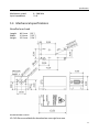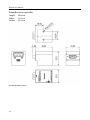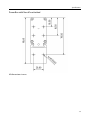
1
with PowerBox
User Manual
User Manual
RGB Lasersysteme GmbH
NovaPro series with PowerBox
Version: 1.2.3
Date: February 24, 2012
This document is protected by copyright. Do not copy or publish this document or parts
of it without written permission of RGB Lasersysteme GmbH.
Product specifications and descriptions in this manual are subject to change without
notice. RGB Lasersysteme GmbH will not be responsible for errors and omissions in this
manual or for direct or incidental damages in connection with the use of this device or
information.
© 2012 RGB Lasersysteme GmbH
Donaupark 13
93309 Kelheim
Germany
Telephone: +49 9441 1750 33 – 0
Website:
http://www.rgb-laser.com
E-Mail:
[email protected]
Contents
1
2
Laser Safety Precautions ...............................................................................................1
Introduction ......................................................................................................................2
2.1
2.2
3
Installation and Operation ...........................................................................................4
3.1
3.2
3.3
3.4
3.5
3.6
3.7
4
Precautions................................................................................................................................... 4
Device Setup ................................................................................................................................ 4
Stand-alone laser operation.................................................................................................... 5
Computer-controlled laser operation .................................................................................. 6
Operation modes ....................................................................................................................... 6
Disconnecting the system ....................................................................................................... 7
Troubleshooting ......................................................................................................................... 7
Computer Control ...........................................................................................................9
4.1
4.2
5
Product Overview....................................................................................................................... 2
Package Contents....................................................................................................................... 3
Ltune Laser Control Software ................................................................................................. 9
Serial Communication ............................................................................................................ 10
Specifications................................................................................................................. 15
5.1
5.2
5.3
5.4
General Specifications ............................................................................................................ 15
Beam Specifications................................................................................................................. 15
Electrical Specifications .......................................................................................................... 16
Mechanical specifications ...................................................................................................... 17
6
Optional system configurations ............................................................................. 20
7
Certification .................................................................................................................... 21
8
Appendix ......................................................................................................................... 22
8.1
List of abbreviations ................................................................................................................ 22
Laser Safety Precautions
1
Laser Safety Precautions
CAUTION: This device emits visible and invisible
LASER radiation. Avoid exposure to the beam!
Lasers emit visible and invisible radiation that may cause
damages to material and person, mainly by thermal
effect. Radiation entering the human eye can damage
the retina, which leads to partial or total loss of vision.
The damage can occur without particular perception or
sensation of pain.
Please consider all protection and safety regulations while handling laser systems. Always
use laser protection glasses for the specified wavelength range.
Never direct the laser towards people. Keep the laser beam away from reflective surfaces
in order to avoid uncontrolled reflections. Do not mount the laser at eye level.
It is your responsibility to guarantee the laser safety as required by law. Please pay
attention to safety regulations DIN EN 61010-1, DIN EN 60825-1:2003-10 and DIN EN
60950 when operating the laser.
The NovaPro series is specified by the United States National Center for Device and
Radiological Health (CDRH) as a class 3b laser product. Visible and invisible laser radiation
is emitted.
Modifications that may affect any aspect of the product’s
performance or intended functions will require re-certification
and re-identification of the product in accordance with the
provisions of 21CFR 1040.10 and 1040.11.
NovaPro laser modules are marked with a warning label as
show on the right.
1
NovaPro User Manual
2
Introduction
2.1 Product Overview
The NovaPro series offers high performance, modulatable laser modules in a small
design. The high quality product „Made in Germany“ guarantees universal capabilities in
almost all fields of applications, with optical output powers up to 1000 mW. High
durability, excellent beam quality and various options for system integration (for example
into the Qioptiq rail system FLS 40) guarantee highest flexibility in industrial, scientific
and medical applications.
Laser Head Features
•
•
•
•
•
•
•
•
Small design
Optical output powers up to 1000 mW
Active Temperature Stabilization
IP67 protected housing, optionally vacuum sealed
Optional fiber coupler
Horizontal, vertical and diagonal mounting options
Produced in highly clean-room atmosphere
Adjustable temperature
Laser Controller Features
•
•
•
•
•
•
•
•
2
Attaches directly to laser head
Highly compact design
Straightforward connection via screw-type terminal block
Digital control via USB
Powered by 12 – 36 V DC
Modulation input analog or digital 0 – 5 V DC
Low speed and high speed modulation inputs
Interlock on/off input
Introduction
2.2 Package Contents
Laser head
In order to provide the best beam quality only high
quality optical components are used within the laser
head. A thermoelectric cooler is integrated for
stabilizing the temperature.
Laser controller
The PowerBox laser controller attaches directly to the
laser head through the D-SUB9 connector with a
locking mechanism. The back side holds a six-pin
screw terminal block, a USB port and two coaxial
modulation inputs (standard version). The terminal
block can be pulled out and removed from the
controller.
Cable
A standard Mini USB cable is used for connecting the laser to a computer or power
supply. The length of the cable is 1.5 m (5 ft).
Software
The CD-ROM includes the Windows application software Ltune for configuring and
controlling the laser system as well as this manual as a PDF file.
3
NovaPro User Manual
3
Installation and Operation
3.1 Precautions
• Take care of all laser safety instructions as described
in chapter 1. Always wear laser protection glasses for the
specified wavelength range.
• Consider regulations for Electrostatic Discharge (ESD).
• Do not open the laser head. Opening the case voids the
warranty and may cause uncontrolled laser radiation.
• Always mount the laser module securely and pay
attention to sufficient heat dissipation.
• Never disconnect the laser head from the controller while connected to the
power supply. This can damage the laser.
• Do not reflect the laser beam back into the laser head. The laser diode could be
damaged if more than 2 % of the emitted power is reflected back into it. Carefully
check all mirroring surfaces of your optical setup for possible back reflections. If
required, use a suitable optical insulator.
• Do not exceed the environment conditions specified in chapter 5.
3.2 Device Setup
1.
2.
3.
4.
5.
6.
4
Attach the PowerBox controller to the NovaPro laser head.
If you have several laser modules, please note that the controllers are not
interchangeable. Make sure the serial numbers on the laser head and the laser
controller match each other.
Move the locking slider on the connector to the locked position.
Connect the pins of the screw terminal block and the modulation inputs as
required. Please see the following section for more details.
Turn on the supply voltage VCC.
After a quick self-test the green POWER LED should be lit continuously and the
RDY output should be high (+ 5 V) .
Installation and Operation
Connector and Pin Assignment
The connectors for the standard version are:
1
2
3
4
5
6
7
8
9
VCC
GND
INT
RDY
TTL
AN
Supply voltage
Ground
Interlock input
Ready output
Digital low-speed modulation input
Analog low-speed modulation input
Digital coaxial modulation input (MMCX)
Analog coaxial modulation input (MMCX)
USB connector
The high speed modulation option does not include the coaxial modulation inputs (7 and
8) and the digital low-speed modulation input (5) on the controller. Instead, a high speed
digital modulation input (MMCX) is placed directly on the back of the laser head.
All pins are low if not connected. For modulation you can choose to use the low speed
terminal block input or higher speed coaxial input, depending on your bandwidth
requirements. The technical specifications for the inputs can be found in chapter 5.
Please note that the input levels are different for low and high speed modulation inputs.
You can also use both low speed and coaxial inputs at the same time. In this case, the
digital inputs are logically-OR combined and the analog inputs added.
Status Indicators
The laser controller includes two LEDs to indicate the laser status:
LED
Status
POWER
On
Power supply connected, self-test successful
Off
Power supply not connected
Flashing
EMISSION
Description
Error
On
Laser active, emission possible (actual emission depends on
modulation mode and input pins)
Off
Laser inactive
Flashing
5 second delay before activating laser
3.3 Stand-alone laser operation
To operate the laser continuously at maximum output power, please connect the three
Interlock, TTL and analog modulation inputs to + 5 V or VCC. The laser starts operation
5
NovaPro User Manual
with a five second delay, as required by CDRH regulation1. Once the laser is active, the
EMISSION indicator is lit continuously. Afterwards, you can turn the laser on and off
instantly by using the TTL modulation input or adjust the output power using the analog
modulation input. In stand-alone operation, the laser operated in “Combined Modulation
Mode”, which means that the laser emission is determined by both analog and digital
modulation inputs.
3.4 Computer-controlled laser operation
The NovaPro series can be controlled via USB. The operation is described in chapter 4.
In order to turn the laser on, please:
1.
2.
3.
4.
Connect the system as described in section 3.2.
For Digital or Analog Modulation Mode, please apply a voltage at the modulation
input (BNC connector). Note that even with an input voltage of 0 V, a small
amount of luminescence may be emitted. For operation in Constant Power
Mode, you don’t need to connect anything to the modulation inputs.
Connect the interlock input + 5 V or VCC .
Start the Ltune application software, set an output power and click on the Power
On/Off button. The laser starts with a 5 second delay as described above.
Note for lasers at 473, 532 and 561 nm: it is recommended to initially operate the laser
at full maximum output power for 5 minutes. Afterwards the output power can be
adjusted to any value. At low output powers these lasers often exhibit multi-mode
emission.
3.5 Operation modes
You can select the operation mode using Ltune or your own custom software. In standalone operation, the laser system is always in Combined Modulation Mode. The technical
specifications for the modulation inputs can be found in chapter 5.
Constant Power Mode
The NovaPro laser systems can be driven in CW mode without an external control
voltage. In this case, the laser emission is constant at 100 % maximum output power.
Analog Modulation Mode
In this mode the optical output power can be controlled by an external voltage at the
analog modulation input connector. The output power is modulated proportional to this
signal.
1
Custom modification without delay is available for OEM integration.
6
Installation and Operation
Digital Modulation Mode
Here, the digital modulation input is used to switch the laser off and on between 0 and
100 % maximum power. The nominal TTL input levels for the low-speed modulation
input are 0 V (laser off) and 5 V (laser on)2 .
Combined Modulation Mode3
In this mode, the laser emission is determined by both analog and digital modulation
inputs. It can be turned on and off using the digital input and the output power can be
adjusted using the analog input.
3.6 Disconnecting the system
Always disconnect the power supply before removing the controller from the laser head
in order to prevent damage to the laser!
3.7 Troubleshooting
If the device is detected by Ltune, but there is no laser emission:
Please make sure that these conditions are met:
• The green LED is lit continuously (if not, please check power supply)
• The interlock pin is at +5 V.
• The power on/off button in Ltune is turned on and an output power larger than
zero is selected.
• Either Constant Power Mode is selected or a proper signal is connected to the
modulation inputs.
If the green LED is flashing, please run Ltune and check the bottom of the window for
error messages.
If the device is not detected when Ltune is started:
First of all, please disconnect the laser from the computer, restart the computer, connect
the laser again and start the Ltune software.
If the laser is still not found: The Ltune software communicates with the laser using a
"virtual serial port". If the driver is installed correctly, it should show up in the Windows
Device Manager. You can open the device manager by clicking Start -> Control Panel (->
Performance and Maintenance) -> System -> Hardware -> Device Manager.
2
However, all signals below 0.8 V are considered as off and above 2.0 V as on.
This mode cannot be selected in the current version of the Ltune software, but is fully supported by
version 2, which will be made available for download on our website www.rgb-laser.com soon. If you need
this feature earlier, please ask our support team for a preview release.
3
7
NovaPro User Manual
In the device manager, please open the "Ports (COM & LPT)" subtree. One of the COM
ports listed there should belong to your laser. If you right-click on the correct item,
choose "Properties" and then the "Driver" tab page, it should read: "Driver Provider: FTDI"
and "Driver Version: 2.8.14.0" (or later). If this is the case, please start Ltune and try to
select this COM port manually by unchecking "Auto-scan all serial ports" in "Device
setup".
If your laser is not listed in the device manager or marked with an exclamation or
question mark, please try the following:
1.
2.
3.
4.
5.
8
Disconnect your laser from the computer and from power supply.
Download http://www.ftdichip.com/Resources/Utilities/FTClean.zip and run this
tool to remove the FTDI driver from your computer.
Reinstall Ltune from the CD.
Reconnect the laser to the computer.
Start Ltune.
Computer Control
4
Computer Control
The NovaPro series includes a USB interface for remote control. The laser can be
controlled with
• The Windows application software Ltune (included) or
• Custom user software via serial communication.
4.1 Ltune Laser Control Software
The NovaPro laser can be configured and controlled using the Ltune software for
Windows. The software features:
•
•
•
•
Modulation mode selection
Output power adjustment
Display of the laser status, configuration and operating hours
Temperature display and adjustment
9
NovaPro User Manual
To install the software, simply run the setup file from the CD-ROM included in the
package. The setup package then installs the application software and the device driver.
For the operating system to properly recognize the device, it’s best if you install the
software first before attaching the device.
The software is tested with 32 and 64 bit versions of Windows 7, Vista and XP. It requires
the Microsoft .NET framework version 3.5, which is already installed on most PCs. If this
framework is not installed, the setup package asks you to install it first. You can find the
setup file for the .NET framework on the CD or download it from Microsoft’s website.
Please note that you need version 3.5 of the framework. Version 4.0 does not include
version 3.5.
After the software is installed, please connect your NovaPro laser to a USB 2.0 port on the
computer. You can use the provided USB cable or almost any other Mini-USB cable.
The software requires the .net framework 3.5, which is already installed on most PCs and
can be downloaded from the Microsoft website, if needed.
Please note that you can change the user interface to a more compact view by clicking
the small button next to “Device properties”.
4.2 Serial Communication
Overview
When the laser controller is connected to a PC and the device driver installed, it shows up
as a virtual COM port and can be accessed from almost any programming language. A
detailed description of the commands and queries is given in the following section.
The command settings are not stored when the system is powered down.
Communication protocol
The commands and queries have the following syntax:
Commands:
command=<parameter value>
A command changes an actual setting. The syntax is the command, followed by an equal
sign and the parameter value. The parameter value is the value to be set. Commands
have no return value.
Queries:
query?
A query returns information about the device or the value of a setting. The syntax is the
query, followed by a question mark. Queries have no parameter value. A query delivers a
return value.
10
Computer Control
Return Code
A return code gives information about the processing of a command or query. There is
always a space character between the return code and the result. The return codes are:
Code
0
1
2
3
4
5
6
7
8
Name
COMMAND_SUCCESS
COMMAND_INVALID
PARAMETER_ERROR
VALUE_INVALID
CODE_INVALID
DEVICE_LOCKED
FUNCTION_NOT_SUPPORTED
COM_TIME_OUT
VALUE_NOT_AVAILABLE
Description
Command successful
Command invalid
Wrong numbers of parameters
Parameter value is out of range
Unlocking code is wrong
Device is locked for this command
This function is not supported
Timeout while reading command (60 s)
This value is currently not available
All commands and queries and all responses from the device are followed by the line
termination string “\r\n” (carriage return & line feed). All instructions have to be written
in capital letters.
Initializing the serial communication
The NovaPro uses following communication settings:
Baud rate
Parity
Data bits
Stop bits
57600
None
8
1
To initialize the controller, send “INIT”. The controller responds with the return code O
(Command successful).
Closing the communication
Send “BYE” to close the connection to the laser controller.
Turning the laser on and off
This command is used to set and read the “Laser Enable” request. The laser can only be
activated if the key switch is in the ON position and the interlock is closed.
Command/
Query
Parameter value
Return code
Return value
O=
0: Delete Enable Request
1: Set Enable Request
COMMAND_SUCCESS
PARAMETER_ERROR
-
O?
-
COMMAND_SUCCESS
0: Enable Request not set
1: Enable Request set
11
NovaPro User Manual
Temperature settings
(Not all laser systems support this function.)
Depending on the laser type, the temperature can be varied in a defined range. The
commands and queries to access the temperature offset, actual temperature and default
temperature of the laser head are:
Command/
Query
Parameter value
T?
-
TD?
-
TO=
Temperature offset in °C
(value between LTN and LTP)
TO?
-
LTN?
-
LTP?
-
Return code
COMMAND_SUCCESS
VALUE_NOT_AVAILABLE
COMMAND_SUCCESS
COMMAND_SUCCESS
VALUE_INVALID
FUNCTION_NOT_SUPPORTED
COMMAND_SUCCESS
COMMAND_SUCCESS
FUNCTION_NOT_SUPPORTED
COMMAND_SUCCESS
FUNCTION_NOT_SUPPORTED
Return value
Temperature in °C
Default temperature in °C
Temperature offset in °C
Lowest adjustable
temperature in °C
Highest adjustable
temperature in °C
The command TO= expects a temperature offset for the default temperature (TD?) to be
decreased or increased. The temperature can be adjusted with a resolution of 0.1 °C.
The highest and lowest possible temperature value can be queried with LTP? and LTN?,
respectively.
Selection of modulation mode
The following commands are used to change the mode of modulation:
Command/
Query
Parameter value
Return code
Return value
M=
A = external Analog
T = external TTL
C = internal CW
M = manual select
COMMAND_SUCCESS
VALUE_INVALID
FUNCTION_NOT_SUPPORTED
M?
-
COMMAND_SUCCESS
12
A = external Analog
T = external TTL
C = internal CW
M = manual select
Computer Control
CW mode
The NovaPro series can be operated in CW mode at constant power between 0 and 100
% of the maximum output power. There is no need to supply an external control voltage.
Command/
Parameter value
Query
P?
Output power in mW
P=
(value between 0 and LP)
-
LP?
Return code
COMMAND_SUCCESS
COMMAND_SUCCESS
VALUE_INVALID
COMMAND_SUCCESS
Return value
Output power in mW
Maximum output power in
mW
TTL modulation
In the TTL modulate mode the output power can be switched between two levels by
applying a TTL compatible (0 / 5 V) external control voltage.
The lower level is set by the PO= command and the higher level by P=. If a level larger
than the maximum output power is specified for P= or a level larger than the P= value is
specified for PO=, the value is decreased to the maximum value.
Command/
Parameter value
Query
PO?
Lower Output level in mW
PO=
(value between 0 and P)
Return code
COMMAND_SUCCESS
COMMAND_SUCCESS
VALUE_INVALID
Return value
Lower Output level in mW
-
Status and device information
The query S? gets the actual status of the laser system including information about the
Enable Request, the key switch, the interlock, active errors and the temperature control.
The query R? returns the operation hours of the laser system. The operation time is the
accumulated time during which the laser was active (red LED on).
Query
S?
R?
DM?
DT?
DS?
DO?
DW?
-
Parameter value
Return code
COMMAND_SUCCESS
COMMAND_SUCCESS
COMMAND_SUCCESS
COMMAND_SUCCESS
COMMAND_SUCCESS
COMMAND_SUCCESS
COMMAND_SUCCESS
DF?
-
COMMAND_SUCCESS
Return value
Current device status (see table below)
Total operating hours [hhhh:mm]
Manufacturer
Device name
Serial number
Software version
Emission wavelength in nm
Available features:
T = Temperature adjustable
H = High speed TTL integrated
D = Drive mode changeable(ACC/APC)
13
NovaPro User Manual
DC?
-
COMMAND_SUCCESS
C = Temperature is controlled
M = External analog and digital modulation
A = Modulation inputs can be combined
R = Round beam
L = Wavelock
E = ECDL laser
W = Water-cooled
B = Multi-mode beam
S = Customized
ACC = Active current control
APC = Active power control
COMBINED = ACC and APC
The result of the status request S? is a bit-wise combination of the following values:
Code
0x01
0x02
0x04
0x08
0x10
Mnemonic
LASER_ON
INTERLOCK_OPEN
ERROR
TEMPERATURE_OK
Description
Laser system in active, radiation can be emitted
(reserved)
The interlock is open
Error is active (error can be read with E? query)
Temperature of laser head is ok
Error status of the laser system
The query E? reads the actual active errors of the laser system.
Query
E?
Parameter value
-
Return code
COMMAND_SUCCESS
Return value
Error code (see table below)
Possible error codes:
Code
0x01
0x02
0x04
0x08
0x10
0x20
0x40
0x80
14
Mnemonic
LASER_HEAD_OVERTEMP
LASER_HEAD_UNDERTEMP
TEMP_SENSOR_OPEN
TEMP_SENSOR_SHORTENED
LASER_DRIVER_OVERTEMP
TEC_CONTROLLER_OVERTEMP
LASER_OVERCURRENT
FATAL_INTERNAL_ERROR
Description
Temperature of laser head is too high
Temperature of laser head is too low
Temperature-sensor connection is broken
Temperature sensor cable is shortened
Temperature of laser driver is too high
Temperature of TEC controller is too high
Current for laser head is too high
Internal error (laser system cannot be activated)
Specifications
5
Specifications
5.1 General Specifications
Noise:
Power stability:
Warm-up time:
Drive mode:
Modulation modes:
Modulation frequency:
Control mode:
Temperature control:
TEC accuracy:
CDRH Classification:
Weight:
ESD protection:
Operating temperature:
Storage temperature:
< 1 % RMS
< 1 % (10 h)
ready for use after 5 sec,
calibrated operation after 3 min
473, 532 and 561 nm: Active power control (APC)
others: Active current control (ACC)
Constant power, analog and digital external modulation
standard version:
200 kHz
473, 532 and 561 nm:
15 kHz4
high speed mod. option: digital 200 MHz, analog 500 Hz
Power, temperature and modulation controllable via USB
active TEC
< 10 mK
Class 3b
94.4 g (laser head)
Level 4
0 °C to 45 °C (non-condensing)
-25 °C to 70 °C
5.2 Beam Specifications
Beam diameter:
Divergence:
Spatial beam mode:
Polarization:
Polarization angle:
Beam alignment:
Pointing stability (10 h):
4
473, 532, 561 nm and round beam option: 1.2 mm circular
other: 1.1 × 2.2 to 1.2 × 4.3 mm
< 0.9 mrad
TEM00
> 100:1 linear
vertical ± 5°
< 5 mrad and < 0.1 mm (compared to base mount)
< 5 µrad/K
An optional acousto-optical modulator (AOM) may be used for faster modulation.
15
NovaPro User Manual
5.3 Electrical Specifications
Power Supply and Control
Supply voltage VCC:
Supply current ICC:
Interlock input:
Ready output:
12 – 36 V
≤ 2 A at VCC = 12 V
0 – 5 V (< 0.8 V: low, > 2.0 V: high)
0 / 5 V (active high)
Absolute Maximum Ratings
The device may be damaged if these values are exceeded.
Supply voltage VCC:
Terminal block inputs:
Coaxial MMCX inputs:
-40 to +40 V
-0.3 to +40 V
Standard version:
0 to 2.0 V
High speed modulation: 0 to 5.5 V
Low-speed Modulation Inputs
Connector type:
Analog / digital input:
Digital input threshold:
Input polarity:
Modulation speed:
Input impedance:
Screw terminal block
0–5V
< 0.8 V: low, > 2.0 V: high
active high
Standard version:
0 – 200 kHz
High speed modulation: 0 – 500 Hz
10 kΩ
Coaxial Modulation Inputs
Standard version
Connector type:
Analog / digital input:
Digital input threshold:
Input polarity:
Modulation speed:
Input impedance:
MMCX coaxial connector
0 – 0.5 V
< 0.2 V: low, > 0.3 V: high
active high
0 – 1500 kHz
50 Ω
High speed modulation option
Connector type:
Analog / digital input:
Digital input threshold:
Input polarity:
16
MMCX coaxial connector
0 – 5.0 V
< 0.8 V: low, > 2.0 V: high
active high
Specifications
Modulation speed:
Input impedance:
0 – 200 MHz
1 kΩ
5.4 Mechanical specifications
NovaPro laser head
Length:
Width:
Height:
63.5 mm
31.0 mm
32.5 mm
(2.5 “)
(1.22 “)
(1.28 “)
All dimensions in mm.
3D CAD files are available for download on www.rgb-laser.com.
17
NovaPro User Manual
PowerBox laser controller
Length:
Width:
Height:
39.0 mm
31.0 mm
32.5 mm
All dimensions in mm.
18
Specifications
PowerBox with NovaPro attached
All dimensions in mm.
19
NovaPro User Manual
6
Optional system configurations
Fiber coupler
Each NovaPro laser system can be equipped with a fiber coupler.
Water cooling system
For operation in extreme conditions, there is a optional water cooling system for the
bottom plate. This ensures an optimal heat dissipation.
Round beam
Circular and other beam shape characteristics are available on request.5
Wavelock
The Wavelock option provides an exceptionally stable single mode emission. Available
for wavelengths of 405, 640, 660, 785 and 808 nm.
5
Please note that the Round Beam option decreases the maximum output power by up to 30 %.
20
Certification
7
Certification
RoHS Declaration of Conformity
The manufacturer
RGB Lasersysteme GmbH
Donaupark 13
93309 Kelheim
declares that the following product
NovaPro
Version 1.0
contains no toxic substances which are specified in the
RoHS Directive 2002/95/EG.
The conformity to RoHS Directive 2002/95/EG is confirmed.
This declaration applies to all models of the above named product
version.
Kelheim, 09.02.2008
Mathias Reichl
21
NovaPro User Manual
8
Appendix
8.1 List of abbreviations
°C
°F
μm
μrad
AC
A
BNC
CDRH
CE
CW
DC
D-SUB9
ESD
Hz
in
K
kHz
LED
m
MHz
mm
mrad
nm
RMS
RoHS
sec
TEC
TEM
TTL
V
VAC
VDC
W
WEEE
22
Degrees centigrade
Degrees Fahrenheit
Microns
Micro radiant
Alternating current
Ampère
BNC connector
Center of Device and Radiological Health
Conformité Européenne
Continuous wave
Direct current
D-SUB9 connector
Electrostatic discharge
Hertz
inch
Kelvin
Kilohertz
Light emitting diode
meters
Megahertz
Millimeter
Milliradiant
Nanometer
Root mean square
Restriction of the use of certain hazardous substances
seconds
Thermo electric cooler
Transverse electromagnetic mode
Transistor-transistor logic
Volts
Volts, alternating current
Volts, direct current
Watt
Waste Electrical and Electronic Equipment