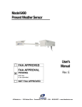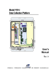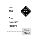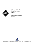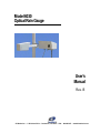
1
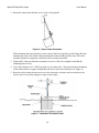
Model 6030 Optical Rain Gauge User’s Manual Rev. B All Weather Inc. • 1165 National Drive • Sacramento, CA 95834 • USA • 800.824.5873 • www.allweatherinc.com Copyright © 2011, All Weather, Inc. All Rights Reserved. The information contained herein is proprietary and is provided solely for the purpose of allowing customers to operate and/or service All Weather, Inc. manufactured equipment and is not to be released, reproduced, or used for any other purpose without written permission of All Weather, Inc. Throughout this manual, trademarked names might be used. Rather than put a trademark (™) symbol in every occurrence of a trademarked name, we state herein that we are using the names only in an editorial fashion and to the benefit of the trademark owner, and with no intention of infringement. All Weather, Inc. and the All Weather, Inc. logo are trademarks of All Weather, Inc. Disclaimer The information and specifications described in this manual are subject to change without notice. Latest Manual Version For the latest version of this manual, see the Product Manuals page under Reference on our web site at www.allweatherinc.com/. All Weather, Inc. 1165 National Drive Sacramento, CA 95834 Tel.: (916) 928-1000 Fax: (916) 928-1165 Contact Customer Service • Phone support is available from 8:00am - 4:30pm PT, Monday through Friday. Call 916-928-1000 and ask for “Service.” • Online support is available by filling out a request at www.allweatherinc.com/customer/support.html • E-mail your support request to [email protected] Model 6030 Optical Rain Gauge User’s Manual Revision History Revision B Date 2011 Oct 31 Summary of Changes Removed references to OEM part numbers, replaced installation drawing with diagrams in the Installation chapter, and better explained options and wiring details Model 6030 Optical Rain Gauge User’s Manual TABLE OF CONTENTS 1. OVERVIEW .........................................................................................................................1 1.1 Accessories ................................................................................................................................ 1 2. SYSTEM DESCRIPTION ....................................................................................................2 2.1 Major Components .................................................................................................................... 2 2.1.1 Sensor Head ..................................................................................................................... 2 2.1.2 Electronics Enclosure....................................................................................................... 3 2.1.3 AC Interface Board .......................................................................................................... 3 3. THEORY OF OPERATION .................................................................................................4 3.1 Sensor Head ............................................................................................................................... 4 4. INSTALLATION ...................................................................................................................6 4.1 Siting and Installation Guidelines ............................................................................................. 6 4.2 Mechanical Installation ............................................................................................................. 8 4.2.1 Preparation ....................................................................................................................... 8 4.2.2 Mount the Sensor Head .................................................................................................... 9 4.2.3 Install the Electronics Enclosure .................................................................................... 11 4.3 Electrical Connections ............................................................................................................. 12 4.3.1 RS-485 Connections to the AWOS Data Collection Platform ...................................... 15 4.3.2 Connecting the Sensor to the AC Power Line ............................................................... 15 5. OPERATION WITH AN AWOS DATA COLLECTION PLATFORM .................................. 16 5.1 Sensor Interface ....................................................................................................................... 16 5.1.1 Physical Level ................................................................................................................ 16 5.1.2 Link Level ...................................................................................................................... 16 5.1.3 Frame Format ................................................................................................................. 16 5.1.4 Protocol .......................................................................................................................... 17 5.2 Data Format ............................................................................................................................. 18 5.2.1 Precipitation Codes ........................................................................................................ 18 5.2.2 Status Codes ................................................................................................................... 19 6. MAINTENANCE ................................................................................................................20 6.1 Triannual Maintenance ............................................................................................................ 20 7. SPECIFICATIONS ............................................................................................................22 8. WARRANTY ...................................................................................................................... 24 Model 6030 Optical Rain Gauge User’s Manual 1. OVERVIEW The Model 6030 Optical Rain Gauge optically measures precipitation-induced scintillation and applies algorithms to determine the precipitation occurrence, type, rate, and water equivalent accumulation automatically. The Model 6030 Optical Rain Gauge measures precipitation by detecting the optical irregularities — known as scintillations — induced by particles falling through a beam of partially coherent infrared light in the sample volume. The induced scintillations are related to the characteristics to the precipitation, and the precipitation rate is determined based on the intensity of these scintillations. In turn, the precipitation rate can be used to determine precipitation accumulation. The Model 6030 Optical Rain Gauge is not affected by many of the environmental factors that cause significant errors with traditional rain gauges. Model 6030 Optical Rain Gauge offers these features. Easy Installation Wide Dynamic Range High Sensitivity Works on Ships and Buoys Low Maintenance No Evaporation or Splash Errors Minimal Wind Effects Not Affected by Insects, Debris, Dust Applications using traditional tipping bucket rain gauges can all be upgraded easily to use the Model 6030 Optical Rain Gauge. The electro-optical design provides for an extremely reliable sensor with a calculated MTBF in excess of 60,000 hours. Unlike mechanical gauges, which collect the precipitation to measure it, the Model 6030 Optical Rain Gauge has no collectors or buckets to corrode or clog. The sensors use automatic gain control circuitry to eliminate the effects of LED output power or dirty optics. In fact, sensor performance is maintained even when over 75% of the light is blocked! Diagnostics alert the user if the signal strength is too low for normal operation. Preventative maintenance, suggested every 6 months, is as simple as cleaning the two optical windows on the unit. 1.1 ACCESSORIES The following accessories and replacement parts are available for the Model 6030 Optical Rain Gauge. Part Number M488173-01 Description Standalone Mounting Kit M404806 Serial Sensor Interface Board M442071 10 A 250 V, 5x20 mm slow blow fuse (F1—AC Interface Board) M442070 5 A 250 V, 5x20 mm slow blow fuse (F2—AC Interface Board — used with 230 V setting) 1 Model 6030 Optical Rain Gauge User’s Manual 2. SYSTEM DESCRIPTION 2.1 MAJOR COMPONENTS 2.1.1 Sensor Head The 6030 sensor head uses a compact optical system to measure precipitation. The sensor head frame is an all-aluminum, welded design. The small box (TX) is the transmitter unit and contains an infrared LED and lens with a disk heater. The large box (RX) contains a receiver assembly consisting of a photo diode, a lens with an aperture slit, a disk heater, electronics, an external thermistor probe, and a connector for the signal/power cable. The wiring between the two heads is inside the welded head frame. The transmit and receive lenses are heated by self-regulating positive temperature coefficient (PTC) thermistor disks to a temperature above the ambient temperature to reduce dew and frost on the lenses. Depending on the ambient temperature, the current drain for the lens heaters can change more than 200 mA. The sensor head is completely sealed from water intrusion at the factory. Exercise care should to avoid drilling or otherwise puncturing the frame. A 15 m cable is supplied to connect the sensor head frame to the electronics enclosure. A mounting plate, an integral part of the sensor head cross arm, is provided to install the head to a user-supplied mast. Two sets of holes in the mounting plate allow the U-bolts supplied with the head to clamp the head to either a vertical or horizontal pipe up to 50 mm in diameter. N o t e: The sensor head frame contains no user serviceable parts - opening the head will void the warranty! 2 Model 6030 Optical Rain Gauge User’s Manual 2.1.2 Electronics Enclosure The electronics enclosure contains the processing electronics, power supplies, and surge protection circuits. The electronics enclosure is a fiberglass NEMA-4X type box with a hinged access door. One power supply, and AC and RS-485 interface modules with surge protection are mounted to the base plate of the enclosure. Figure 9 shows the locations of these components inside the enclosure. All the units in the enclosure are field-replaceable. The electronics enclosure is mounted with the supplied fastener hardware using the four (4) mounting holes on the enclosure. N o t e: Exercise care to avoid drilling or otherwise puncturing the electronics enclosure. 2.1.3 AC Interface Board Two fuses are located on the AC Interface Board (see Figure 1). Though installed, fuse F2 is not used. Replace the fuses only with fuses of the same rating, as shown below. F1 10 A 250 V, 5×20 mm slow blow F2 5 A 250 V (not used) Figure 1. AC Interface Board Note that there is a plastic safety shield over the AC Interface Board. The fuses extend through holes in the shield, and may be replaced without removing the shield. 3 Model 6030 Optical Rain Gauge User’s Manual 3. THEORY OF OPERATION 3.1 SENSOR HEAD The sensor head is a self-contained unit consisting of electro-optical components, heaters, a microprocessor, and integral cabling to connect with the electronics enclosure. The sensor measures precipitation by detecting the optical irregularities induced by particles falling through a beam of partially coherent infrared light (in the sample volume). These irregularities are known as scintillation. The twinkling of stars is a familiar example of scintillation. By detecting the intensity of the scintillations which are characteristic of precipitation, the precipitation rate is determined. Precipitation is measured using the sensor head “in-beam” optics. Figure 2. Optical Rain Gauge Theory of Operation The Model 6030 Optical Rain Gauge consists of these components. • A transmit modulator and infrared LED (TX) • A transmitter optical lens assembly • A receiver optical lens assembly • A photo detector and preamplifier (RX) 4 Model 6030 Optical Rain Gauge User’s Manual An Automatic Gain Controlled (AGC) normalizer A signal processor A temperature probe A microprocessor and communications subsystem The transmitter portion of the sensor head uses an infrared LED as a light source that is modulated to eliminate interference in the system caused by background light. The LED has a very long life time, has a relatively low power draw, is invisible to the eye, and presents no radiation hazard to the user. The LED is housed in the smaller of the sensor head boxes. A lens is used to collimate the LED’s carrier-wave modulated light into a slightly diverged beam. The transmit and receive lenses are both heated by self-regulating positive temperature coefficient (PTC) thermistor disks to a temperature just above the ambient temperature to reduce dew and frost on the lenses. The larger sensor head rectangular box houses receive optics, DC regulator, the AGC, signal processing electronics, temperature probe, and microprocessor. The receive lens focuses the transmitted light onto a photo diode. The scintillations in light intensity are thus detected and amplified. A wide dynamic range Automatic Gain Control (AGC) circuit normalizes the precipitationinduced scintillation signal to the carrier-wave modulated light. Thus errors from variations in the source intensity caused by LED aging or dirt on the lenses are eliminated. The demodulated scintillation signal is then further filtered, processed, and averaged. The statistical average of the measured scintillation signals gives an accurate measurement of instantaneous precipitation rates. The microprocessor uses an adaptive baseline technique to optimize the sensitivity of the Optical Rain Gauge continuously. This technique ensures that the sensitivity is not affected by normal atmospheric turbulence, and it minimizes the chance of false alarms (such as reporting precipitation when none occurs). The processor uses the scintillation signal and temperature probe data to determine the precipitation type and calculates the total water equivalent with the following formula. mm mm/h h RR is the precipitation intensity, and k is a constant that depends on the ambient temperature, T, as follows. T > 3°C T < =4°C -4°C < T < 3°C k=1 k = 0.607 exp 3 12 The microprocessor also provides diagnostic data about the condition of the sensor. The output is an RS-232 data string that is converted to RS-485 by the Serial Sensor Processor in the electronics enclosure. 5 Model 6030 Optical Rain Gauge User’s Manual 4. INSTALLATION 4.1 SITING AND INSTALLATION GUIDELINES The Model 6030 Optical Rain Gauge may be installed almost anywhere outdoors. An area free and clear of obstructions and contamination sources will help insure good sensor performance. In general, the sensor should be located on level or slightly sloping ground where the sensor site will be exposed to the same environment as the area around it. Ideally, the area around the site should be free of buildings, trees, and other obstructions. All Weather, Inc. recommends that the siting and installation follow the general guidelines established by the Office of the Federal Coordinator for Meteorology (OFCM). The Federal Standard for Siting Meteorological Sensors at Airports, OFCM document # FSM-S4-1987, makes the following recommendations. 1. Distance from Obstructions — The distance between the sensor and obstructions such as trees or buildings should be at least 2 times the height of the obstruction on all sides. For example, if a tree20 m high is located alongside the sensor, the sensor should be at least 40 m away from the tree. This restriction reduces the effects of wind turbulence created by the nearby obstruction and makes the precipitation measurement more representative. Do not locate the sensor where tree branches or wires will hang over the sensor! 2. Separation from Turbulence and Contamination Sources — Do not mount the sensor near building exhaust vents, strobe lights, or sources of smoke or steam. Where possible, locate the unit as far away from runways and roads as possible to reduce optics fouling from wind-blown road dirt. An ideal minimum distance is at least 30 m. 3. Sensor Height, Rigidity, Verticality, and Orientation — The OFCM recommends that the Optical Rain Gauge be mounted at a height of 10 ft (3 m). This height is not always possible because of constraints imposed by the site. Mounting the sensor head lower than 2 m or higher than 5 m is not generally recommended. 4. For AWOS installations, All Weather, Inc. recommends that the sensor head should be mounted on a mast with a diameter of 50 mm (2") that is set in a concrete foundation is recommended. The electronics enclosure should be nearby, keeping in mind that the cable extending from the sensor head is 15 m long. The installation must be rigid so that wind-induced vibration does not cause false alarms. This can be accomplished by mounting the sensor to a thick wall pipe such as “Schedule 40” type or to a rigid boom arm 1 m in length or shorter. The Optical Rain Gauge may be mounted on the top of a building if it located near the center of the building away from the wind turbulence that may occur near the edges. The sensor head must be mounted vertical within ±2 degrees so that the line aperture on the inbeam lens is horizontal. 6 Model 6030 Optical Rain Gauge User’s Manual 5. The sensor head is generally oriented with the transmitter head on the north side (in the Northern hemisphere) so that the receiver optics face north. Align the sensor head so that the receive lens faces north. If the orientation can be altered to either side of north to obtain a “view” with fewer or more distant obstructions, it is generally acceptable to alter the orientation up to ±30 degrees from north. SUGGESTION: Take a picture at the installation site in each direction (north, east, south, and west) to record the topography and obstructions for future reference. 7 Model 6030 Optical Rain Gauge User’s Manual 4.2 MECHANICAL INSTALLATION 4.2.1 Preparation The sensor and site should be readied prior to beginning the installation. SITING GUIDELINES Sensor head mounted 2–5 m above ground Rigid mounting pole In-beam lens aperture horizontal to ±2 degrees Receiving (RX) lens facing away from sun (north in Northern Hemisphere) No overhanging trees, wires, or roof lines Distance between sensor and closest obstruction at least 2 times obstruction height As far from road, runway, and contamination sources as possible The 6030 Optical Rain Gauge is packed in two heavy-walled corrugated cartons. One carton contains the electronics enclosure and the larger, narrow carton contains the sensor head and cables. Also packed in this carton are the sensor head U-bolt mounting hardware, and electronics enclosure mounting hardware. When opening the cartons, be careful to avoid spilling the contents. Report any shortages or shipping damage to All Weather Inc. within 3 days. CAUTION! Do NOT drill holes in any portion of the sensor head or electronics enclosure! Doing so will void the warranty and may allow water to enter the enclosure! Site Preparation 1. Choose the site using the guidelines in Section 4.2.1. 2. Following applicable electrical and building codes, install a concrete mounting base, mast or tower, AC power cable, RS-485 signal cable, and ground rod. 8 Model 6030 Optical Rain Gauge User’s Manual 4.2.2 Mount the Sensor Head The sensor must be securely installed and correctly oriented to work properly. Figure 3. Mounting Sensor Head 1. Attach the sensor head using the two U-bolts to connect the mounting plate on the sensor head and the mounting bracket with the ¼-20 hex locking nuts as shown in Figure 3. To mount the head to a vertical mast or tower section, install the U-bolts and mounting bracket horizontally. To mount to a horizontal tower section or boom arm, install them vertically using the same holes. Note that the metallurgy of the stainless U-bolts will cause the nuts to seize to the U-bolts and twist them off. Lubricate the threads with anti-seize compound before assembling. Do not tighten the nuts completely until the sensor head is installed on the mast or tower and is oriented on the north-south axis as shown in Figure 4. 9 Model 6030 Optical Rain Gauge User’s Manual 2. Rotate the sensor head until the receive lens is facing north. Figure 4. Sensor Head Orientation When mounting the sensor head on a tower, choose the tower leg that gives the larger head an unobstructed view to the North without rotating the head assembly into the tower. The head assembly should be completely outside the tower as much as possible. 3. Tighten the U-bolt nuts when the orientation is correct. (Do not overtighten such that the mounting plate is bent). 4. Use a large-diameter (8–12 AWG) ground wire to connect the ¼-20 ground stud on the bottom of the sensor head to a copper-clad ground rod close to the base of the mast (see Figure 5). 5. Route the cables along the mast or tower to the electronics enclosure and secure them to the mast or tower every meter using tie-wraps or other straps. Figure 5. Installation of Ground Cable 10 Model 6030 Optical Rain Gauge User’s Manual 4.2.3 Install the Electronics Enclosure One mounting kit option is available to mount the electronics enclosure. Standalone Mounting Kit (AWI part number M488173-01) Attach the electronics enclosure to the Unistrut brackets using the hardware supplied with the sensor. Figure 6 shows the mounting arrangements. Figure 6. Standalone Enclosure Mounting Figure 7 shows the details of securing the mounting hardware. Figure 7. Mounting Hardware Details 11 Model 6030 Optical Rain Gauge User’s Manual These additional steps will help keep the mounting secure and corrosion-resistant. Apply anti-seize compound to all external threaded connections. Once the installation of the enclosure has been completed, apply a light spray of corrosion block to all metallic connectors and threaded fasteners. 4.3 ELECTRICAL CONNECTIONS Figure 8 shows the external connections at the bottom of the enclosure. AC power conduit. Signal cables from sensor head. Serial connection to DCP. AC POWER CONDUIT SERIAL CABLE TO DCP FROM SENSOR HEAD Figure 8. External Connections at Enclosure Bottom Route the cable from the sensor head to the bottom of the electronics enclosure. Secure the cable to the mast using tie-wraps or other straps. 1. Route the cable from the sensor head into the electronics enclosure as shown in Figure 8. 2. Connect the wires to the connector on the DIN rail shown in Figure 9 according to the wiring diagram in Figure 10. 12 Model 6030 Optical Rain Gauge User’s Manual Figure 9 shows the layout of the various electronics subassemblies inside the electronics enclosure. SERIAL SENSOR INTERFACE J2 DC OUT DC POWER SUPPLY J1 AC IN H4 1234567 H1 5 4 3 2 1 115/230 EMI FILTER FUSE ON OFF 2 3 4 5 6 7 8 GND F1 S1 FUSE TB1 12 3 AC INTERFACE BOARD SENSOR HEAD DCP Figure 9. Optical Rain Gauge Subassemblies Inside Enclosure 13 Model 6030 Optical Rain Gauge User’s Manual Figure 10 summarizes all the signal and power wiring for the Model 6030 Optical Rain Gauge. Sensor Interface Processor Board TB1 Pin Function Color 4 RS-485 (+) GREEN 5 RS-485 (–) BROWN 6 GROUND BLACK 7 DC + RED AC Interface Board TB1 Pin Function Color 1 HOT BLACK 2 NEUTRAL WHITE 3 GROUND GREEN 6030 OPTICAL RAIN GAUGE YEL BLK RED BLK BLU BLK GRN BLK RED F1 DC + (2) BLK 2 DC (10) 3 4 5 6 7 DC (9) 8 DC + (1) DCP RED BLK WHT from CONDUIT FITTING GND WHT BLK 1 RS-232(Tx) RS-232(Rx) RS-232(GND) RS-485(+) RS-485() GND DC INPUT(+) RS-485 RS-485+ RS-485 RS-485+ TB2 3 2 1 2 3 4 5 6 7 GND ON CABLE OFF TB1 RED WHT BLK GRN BRN BLK RED DC = AND DC CONNECTIONS REFER TO DC POWER SUPPLY HEADER J2 TB4 10 9 8 7 6 5 4 3 2 1 SENSOR INTERFACE PROCESSOR M404802 POWER INTERFACE BOARD 5 J1 4 5 4 3 2 1 3 2 1 BLU BRN M438210 POWER SUPPLY Figure 10. Optical Rain Gauge Signal and Power Wiring 14 Model 6030 Optical Rain Gauge User’s Manual 4.3.1 RS-485 Connections to the AWOS Data Collection Platform RS-485 connections are made to the Serial Sensor Interface located in the upper right side of the electronics enclosure. A 3-wire connection to the AWOS Data Collection Platform (DCP) is used. Before proceeding, verify that the 6030 electrical power is turned “OFF.” 1. If the shielded RS-485 cable is not already connected to the DIN rail connector and the Serial Interface Processor, connect the WHITE RS-485(+) signal cable to terminal 6, connect the BLACK RS-485(–) signal cable to terminal 7, and connect the RED GND signal cable to terminal 8 of the DIN rail terminal block. 2. Feed the free end of the shielded RS-485 cable through the serial cable gland shown in Figure 8. 3. Strip and tin the ends of the wires. 4. Route the cable through a cable gland on the DCP and connect the three wires inside the DCP to TB4 pins 1 (WHITE), 2 (BLACK), and 7 (RED). 5. Ensure that none of the wires are stressed, then hand-tighten the gland seals on the DCP enclosure and on the Model 6030 Optical Rain Gauge enclosure. 4.3.2 Connecting the Sensor to the AC Power Line Connections are made to the AC interface module inside the electronics enclosure AC power connections are made to the AC Interface Board located in the lower center of the electronics enclosure. A 3-wire, single-phase AC source is required consisting of hot, neutral, and earth ground connections. WARNING Turn off electrical power at the source before making the electrical connections to the sensor! 1. Install a conduit fitting at the location shown in Figure 8. Feed the power cable through the conduit fitting. A 3-wire 16 to 18 AWG cable is recommended. 2. Crimp fork type terminals to the ends of the wires. 3. Connect the three power cable wires to the AC Interface Board terminal blockTB1 pins 1 (LINE), 2 (NEUTRAL), and 3 (GND). 15 Model 6030 Optical Rain Gauge User’s Manual 5. OPERATION WITH AN AWOS DATA COLLECTION PLATFORM 5.1 SENSOR INTERFACE The Model 6030 Optical Rain Gauge responds to a poll from the DCP for the setup, operation, and status of the sensor. 5.1.1 Physical Level The serial signal output from the Serial Sensor Processor consists of a three-wire RS-485 connection. 5.1.2 Link Level Data transfer across the interface is implemented via a serial, ASCII encoded, half duplex, 4800 bps, asynchronous transfer link. Data transfer in the DCP-to-sensor direction is limited to a poll command ("PRWX00\r\n"). Data transfers in the sensor-to-DCP direction are fixed-format ASCII strings terminated with a carriage return (<CR>). 5.1.3 Frame Format The standard output frame format is shown below. Details of the data fields are presented in a later section. Each of the transmitted characters are eight (8) bit (msb - bit 7 - always 0), no parity ASCII (decimal codes 0 to 127), with 1 stop bit. The status code and other information, is formatted in this way as printable ASCII characters to aid in system debugging and field maintenance. The output message from the interface computer in response to the poll consists of the following string of characters. Position Contents Description 1 <blank><blank><equals sign> start of message string 4 W_ _PppppSssss W plus _ _ (no present weather codes) P plus rain rate in four digits with floating-point decimal (0.001 to 9999) S plus four-digit status code (see Section 0) 17 <blank> 18 X000L000K000H000T000 38 <blank> 39 sensor crc error counter <blank> sensor input msg counter no engineering data displayed <blank> 4-character CRC<cr><lf> crc from position 4 up to but not including the crc itself no engineering data displayed 16 Model 6030 Optical Rain Gauge User’s Manual 5.1.4 Protocol In order to keep the interface design effective and simple, the protocol does not support unsolicited messages to the DCP. In other words, the only time the sensor is allowed to transmit a message to the DCP via this link is in direct response to a poll transmission from the DCP, which requires the return of the standard data reply string. Note that the sensor is sampling data continually (every 5 seconds) and processing the precipitation algorithm (once a minute typical). In most cases, the sensor’s response time to a poll will begin within a second or two after receiving the poll, but the response time could be several seconds in unusual circumstances. Avoid these hang-ups by waiting at least 10 seconds before timing out and trying another poll. 17 Model 6030 Optical Rain Gauge User’s Manual 5.2 DATA FORMAT The raw weather information from the sensor head is encoded in the reply message as follows. Byte Description Value 1 2 3-4 5 6-9 10 11-14 15 16 17-19 20 21-23 24 25-27 28 29-31 32 33-35 36 Start of transmission Weather type marker Present weather field Precipitation rate marker Precipitation rate field Status field marker Status field Blank Carrier raw data field marker Carrier 1 min average raw data Low raw data field marker Low 1 min average raw data Particle raw data field marker Particle 1 min average raw data High raw data field marker High 1 min average raw data Temperature field marker Temperature field Blank = W __ P pppp S ssss 0x20 X 000 L 000 K 000 H 000 T 000 0x20 The various fixed fields used in the above poll response are explained here. 1. The capital letters “W”, “P”, “S”, “X”, “L”, “K”, “H”, and “T” above serve as place markers for the Weather, Precipitation, Status, Carrier, Low, Particle, High, and Temperature data fields to follow. These markers are fixed in position and coding. They are included within the format to simplify manual interpretation of the sensor output. 2. No present weather data are reported by this sensor, so the field displays _ _. 3. pppp is a four-byte field indicating the precipitation rate. 4. The remaining fields have no data and display zeroes. 5.2.1 Precipitation Codes The precipitation rate is reported as a 4-byte field with the number in a floating-point format, varying from 0.001 to 9999. Zero is formatted as four zeros (“0000”). The units are millimeters/hour for the rain rate averaged over a one-minute period. 18 Model 6030 Optical Rain Gauge User’s Manual 5.2.2 Status Codes The status codes are a convenient way for the sensor to report the sensor condition. The status field, denoted by s s s s (four bytes) in the data output format, is a four-byte field of sensor status bytes. The codes can be interpreted as shown in the table below. S BYTE 10 BIT 0 STATUS OK BIT 0 1 STATUS OK Error S S S S 11 12 13 14 BIT 0 STATUS OK BIT 0 STATUS OK A status code of 0 in bytes 11, 12, 13 or 14 indicates “no problem,” while a 1 for byte 12 means there is a problem in the sensor head. Example Status codes read S0180. Interpret this code as follows. Byte 11 = 0 Byte 12 = 1 Byte 13 = 0 Byte 14 = 0 OK Error (Sensor Head probably bad) OK OK Solution Wait for 5 minutes to verify that the microprocessor resets. If the status code still reads S0100, replace the Sensor Head and recheck the status code. After 5 minutes (when the microprocessor resets) the status codes should now be S0000. In normal operation (excluding the first five minutes after reset or power-up), the status bytes will be all low (0000). The host system should take action to alert maintenance personnel of a possible problem. In addition, data from the sensor will be disregarded and a “missing” report issued. (Note that the sensor does not necessarily stop outputting data when a status bit flags an error condition.) 19 Model 6030 Optical Rain Gauge User’s Manual 6. MAINTENANCE The Model 6030 Optical Rain Gauge is designed for high reliability and low operator maintenance. The only scheduled maintenance is to periodically clean the lenses. In most locations, cleaning the lenses every four months is recommended. Historically, the sensors have operated unattended for several years without any degradation in performance. Use the table provided to record the maintenance performed. Equipment Required Clean Cotton Cloth or Lens Tissue Common Household Glass Cleaner 6.1 TRIANNUAL MAINTENANCE 1. Clean Lenses Cleaning the lenses should be done with lint-free cloth and cleaning solution. Clean the lenses by first spraying the lens cleaner on the lens and then wipe gently to prevent scratching the glass optics. In actual practice, moderate dust buildup and scratches on the lenses will not have any discernible effect on the instrument. 2. Check Lens Heaters With a clean finger, touch the lenses in front of the disk-shaped heater that is bonded to the lower inside surface of both lenses. The lens surfaces should be slightly warmer to the touch than the ambient temperature. 3. Comb Test Using a pocket comb, stroke it up and down vertically in front of the receiver lens as shown in Figure 11 for ~1 minute. Do not block the beam for any length of time. Look at the data on the DCP screen to make sure it varies as the comb is moved around. Figure 11. Comb Test Illustration 20 Model 6030 Optical Rain Gauge User’s Manual Maintenance Log Date Date Clean Lenses Verify Lens Heaters Comb Test 21 Date Model 6030 Optical Rain Gauge User’s Manual 7. SPECIFICATIONS Parameter Specification Rain Dynamic Range 0.1 – 500 mm/h Rain Accumulation 0.1–999,999 mm Rain Accumulation Resolution 0.001 mm Rain Accumulation Accuracy 5% of accumulation Snow Dynamic Range Snow Accumulation 0.01–50 mm/h water equivalent 0.001–999,999 mm water equivalent Snow Accumulation Resolution 0.001 mm Snow Accumulation Accuracy 10% of accumulation Time Constant 10 s Data Update Rate Once per minute Serial Output RS-485 Output Format ASCII characters Baud Rate Serial Port Parameter Setting 4800 bps 8-N-1 (8 data bits, no parity, 1 stop bit) Power Requirements Supply Voltage Transient Protection 115/230 V AC, 50/60 Hz, 50 W AC power and RS-485 signal lines fully protected Environmental Operating Temperature -40 to +50ºC (-40 to +122ºF) Storage Temperature -50 to +60ºC (-58 to +140ºF) Relative Humidity 0–100%, noncondensing 22 Model 6030 Optical Rain Gauge User’s Manual Parameter Specification Mechanical Controller Assembly Enclosure NEMA 4X fiberglass Sensor Assembly Mounting Controller Assembly Sensor Assembly Dimensions 2.5" (6.35 cm) dia. mast Unistrut mounted 11.5 cm H × 26.4 cm W × 73.0 cm D (4.5" H × 10.4" W × 28.75"D ) Controller Assembly 36 cm W × 41 cm H × 20 cm D (14" W × 16" H × 8" D) Sensor Assembly 4 kg (8.8 lb) Controller Assembly 10 kg (22 lb) Shipping Weight (2 boxes) 16 kg (35 lb) Weight 23 Model 6030 Optical Rain Gauge User’s Manual 8. WARRANTY This equipment has been manufactured and will perform in accordance with requirements of FAA Advisory Circular 150/5220-16B. Any defect in design, materials, or workmanship which may occur during proper and normal use during a period of 1 year from date of installation or a maximum of 2 years from shipment will be corrected by repair or replacement by All Weather Inc. 24 All Weather Inc. 1165 National Drive Sacramento, CA 95818 Fax: 916.928.1165 Phone: 916.928.1000 Toll Free: 800.824.5873 6030-001 Revision B December, 2011