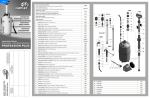
1
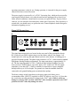
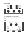
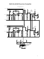
Modular Series
Ultra 4B SE Special Edition
Stereo Phono/Line Preamplifier
User’s Manual
Phono Line1 Line2
Mapletree Audio Design
Balance
Volume
Ultra 4B SE Stereo Preamplifier
Rev. Feb. 22/13
Mapletree Audio Design
Lloyd Peppard
R. R. 1, Seeley's Bay, Ontario, Canada, K0H 2N0
(613) 387-3830
www.mapletreeaudio.com
[email protected]
© Copyright Lloyd Peppard 2002-2013
-Specifications are subject to change without notice-
Introduction
_
The Mapletree Audio Design Ultra 4B SE Stereo Phono/Line Preamplifier offers the
audiophile a number of desirable features:
? ? Compact chassis layout for use with separate power supply for low noise.
? ? Exclusive use of NOS octal tubes, known for low distortion and musicality.
? ? Switchable for use with 12SN7GT or 6SN7GT tubes.
? ? Precise RIAA equalization (±0.5 dB) using non-interacting passive and active filters.
? ? High input impedance and low output impedance.
? ? Parallel output jacks for bi-amp or headphone amplifier applications.
? ? Phono gain of 48 dB suitable for all moving magnet (MM) and high-output moving
coil (MC) phono cartridges.
? ? Audio grade polypropylene and polystyrene film capacitors in signal path.
Power Supply Connections______
The Mapletree Audio Design PS 2 power supply provides +12 VDC (regulated) heater
supply voltage and +200 VDC B+ plate supply voltage at a current of 15 mA (see
specifications). It utilizes a slow start cathode type rectifier tube (6X5GT) in conjunction
with low-noise ultra high-speed diodes to achieve all the advantages of tube rectification
(low noise, soft startup) with the high efficiency of a bridge rectifier topology.
The separate power supply eliminates induced hum originating from power supply
circuitry and components. The power connections to the preamplifier chassis are made
through a special 3-conductor power cord that plugs into jacks located on the rear panels
of the power supply and preamplifier chassis.
CAUTION: Do not operate the power supply when it is not connected to the
preamp. Damage of components may result.
Once the interconnecting power cord is securely attached between the two chassis and the
line cord is plugged in, the power supply can be turned on. The pilot lamp on the power
supply chassis indicates that the unit is on. It takes about 30 seconds for the tubes to reach
2
operating temperature ready for use. During operation, is it normal for the power supply
chassis to become warm to the touch.
The power supply is protected by a 1 A/250 V fast-acting fuse, which can be accessed by
removing the bottom chassis cover after the unit has been unplugged for at least 60 sec.
Under normal conditions, it should not be necessary to replace the fuse. If power fails to
come on, you can check the fuse and replace with a spare if necessary. If the fuse blows a
second time, you should not try to operate the unit. Contact Mapletree Audio Design for
information regarding service.
Signal I/O Connections______
1
12SN7
1 Out 2
Gnd Phono
1 Line 2
L R
6SN7
The signal input/output jacks are located on the rear panel of the preamplifier chassis.
RCA jacks are provided for phono input, two line inputs, and two line outputs. Left
channel jacks are at the top and right channel jacks are at the bottom. A binding post is
provided for phono ground. The phono input resistance is 47 k? ? which matches standard
MM phono cartridge loading requirements. The input capacitance is approximately 50
pF. The line input impedance is 470 k? ??which provides minimal loading of any line
source such as CD/DVD player, tape deck, tuner, or PC sound card. The line output
impedance is less than 500 ? ? which is suitable for connection to a power amplifier
through cables up to 10 ft in length. The ground wire from the turntable should be
connected to the ground binding post to minimize hum pickup.
The heater voltage switch located next to the power input jack allows you to
accommodate either 12SN7GT (supplied) or 6SN7GT tubes in your Ultra 4A. Note that
the switch does not affect the heater voltage for the 12SC7 tubes. While it will do no
damage to switch to 6SN7 position with 12SN7 tubes installed, operation in the 12SN7
position with 6SN7 tubes may damage the tubes.
3
Front Panel Controls
Phono Line1 Line2
Mapletree Audio Design
Balance
Volume
Ultra 4B SE Stereo Preamplifier
The front panel controls are (left to right) the 3-position Source selector switch (PhonoLine1-Line2), the Balance control, and the Volume control, which
adjusts the gain of both channels simultaneously. If you find that you hear pops from your
speakers when switching between sources, turn down the volume control before
switching.
Tubes____
12SC7 (L)
12SN7GT (L)
12SC7 (R)
12SN7GT (R)
4
Vacuum tube socket locations are shown in the diagram on p. 6. The 12SC7s are toward
the rear of the chassis. The tubes supplied are new-old stock (NOS) and have been pretested. A burn-in period of several hours may be needed to achieve the best sonic
performance. Tube life should be thousands of hours. Aging tubes may result in a
reduced gain in one or both channels or an increase in noise levels. Infrequently, a heater
may burn out which is indicated by total loss of sound. Replacement tubes can be
obtained from several suppliers in the U. S. and Canada. Mapletree Audio Design will
attempt to provide replacement tubes to customers at cost plus shipping. Some listeners
enjoy trying different brands and variants of tubes. The heater voltage selector switch
permits the use of 6SN7GT (or the 5692 special red version) tubes of NOS or current
manufacture. The highly regarded 12SX7GT is equivalent to the 12SN7GT.
Warranty___
Assembled components are warranted for 2 years to the original purchaser for failure of parts
(excluding tubes) and workmanship. Tubes are warranted for 90 days exclusive of shipping cost.
Service, including parts and labor (but excluding shipping), is free within the warranty period.
5
MAD Ultra 4B SE Phono/Line Preamplifier
© Copyright Lloyd Peppard 2002-2013
Rev. Jan. 21/13
J3a
2
SW1a
Source
L. Line inputs
1
R21a
475K 1%
R20a
475K 1%
C1a
0.012 2%
3
R1a
chassis 47.5K
1%
C2a
0.1/400
V1a
12SC7820C3a
pF 2%
R6a
432K 1%
2
L. Phono input
V2a
12SN7GT
R11a
47.5K 1%
R3a
332K 1%
J1a
A
B
C
J2a
1
1
6
R7a
221K 1%
R8a
+55 V
100K 1%
5
C4a
0.1/400
4
R5a
432K 1%
R9a
221K
1%
R4a
3.3M 1%
R2a
3.3M 1%
C7a
1/200
2
P1a
100K
Volume
1
C5a
0.001 5%
3
C8a
0.1/400
4
P2
Balance
100K
5
L. outputs
6
R14a
511K
1%
D1a
red LED
J4a
C9a
1/200
J5a
R17a
R15a 1M 1%
1K 1%
R16a
10K 1%
J7 Gnd.
Ground Bus
J3b
SW1b
Source
2
R. Line inputs
1
J2b
R20b
475K 1%
R21b
475K 1%
+76 V
J1b
C1b
0.012 2%
6
R2b
3.3M 1%
1
+71 V
C8b
0.1/400
4
R. outputs
R14b
511K
1%
D1b
red LED
B
5
C9b
6
1/200
+52 V
3
R9b
221K
1%
J4b
J5b
R15b
1K 1% R17b
1M 1%
+51.8 V
R16b
10K 1%
A
+200 V
+172 V
+144 V
R18
22K 2W 5%
C12
100/400
P1b
100K
Volume
C5b
0.001 5%
R5b -0.86 V
432K 1%
C
2
1
C4b
0.1/400
R4b
3.3M 1%
V2b
12SN7GT
C7b
1/200
R7b
221K 1%
R8b
+63 V
100K 1%
5
4
+
+200 V
R11b
47.5K 1%
V1b
12SC7820C3b
pF 5%
R6b
432K 1%
1
-0.67 V
R1b
47.5K
1%
C2a
0.1/400
2
3
R. Phono input
+172 V
+144 V
R3b
332K 1%
A
B
C
R19
5.1K 2W 5%
C11
100/400
+
_
8
8
12 VDC
+
7
7
8
8
1
3
7
12SC7s
12 V
4
7
2
J6
Power In
6V
SW2
Heater Voltage
12SN7s
6
Parts List______
Reference No.
C1a,b
C2a,b, C4a,b, C8a,b
C3a,b
C5a,b
C7a,b, C9a,b
C11a,b, C12a,b
D1a,b
J1a,b–J5a,b
J6
J7
P1a,b
P2a,b
R1a,b, R11a,b
R2a,b, R4a,b
R3a,b
R7a,b, R9a,b
R5a,b, R6a,b
R8a,b
R14a,b
R15a,b
R16a,b
R17a,b
R18
R19
R20a,b, R21a,b
SW1
SW2
V1a,b
V2a,b
Description
0.012uF/160V 2% polystyrene capacitor
0.1uF/400 V polypropylene film capacitor
820pF/630V 2.5% polystyrene capacitor
0.001uF/100 V 5% polypropylene capacitor
1uF/200 V polypropylene film capacitor
100uF/400V electrolytic capacitor
10 mA red LED
RCA gold plated phono jack
4-pin chassis jack (power in)
Ground binding post
100K dual audio taper potentiometer
100K linear potentiometer
47.5K 0.5W 1% metal film resistor
3.3M 1W 10% carbon film resistor
332K 0.6W 1% metal film resistor
221K 0.6W 1% metal film resistor
432K 0.6W 1% metal film resistor
100K 0.5W 1% metal film resistor
511K 0.6W 1% metal film resistor
1K 0.6W 1% metal film resistor
10K 0.6W 1% metal film resistor
1M 0.5W 1% metal film resistor
22K 2W 5% metal oxide resistor
5.1K 2W 5% metal oxide resistor
475K 0.6W 1% metal film resistor
3 position, 4-pole rotary switch (2 poles used)
DPDT heater voltage selector switch
12SC7 tube
12SN7GT tube
7
Circuit Operation______
Referring to the schematic diagram, both channels are identical. The following
description refers to either channel unless otherwise noted. The phono input signal is
applied to input jack J1, loaded by resistor R1, then capacitor coupled to the grid of the
first section of the 12SC7 which is configured as a common-cathode voltage amplifier.
Capacitor C1 sets the low frequency breakpoint in the RIAA equalization curve at 50 Hz.
The negative grid bias is obtained through the grid resistor R2. The output from this stage
is capacitor coupled through C2 to the second stage which uses the second section of the
12SC7 also configured as a common-cathode voltage amplifier. The feedback network
consisting of R5, R6, and C3 implements the turnover frequency of the RIAA curve at
500 Hz. Bias is again obtained through the leakage grid current flowing through the 3.3
M? resistor R4.
The signal is then capacitor coupled through C4 to the phono terminal of the source
selector switch (SW1). The passive network comprised of R8 and C5 implements the
roll-off frequency of the RIAA curve at 2130 Hz. The selector switch is used to steer
either the amplified phono signal or one of two line input signals (jacks J2 and J3) to the
third stage, which utilizes the first section of the 12SN7GT in a common-cathode voltage
amplifier configuration giving a gain of around 22 dB. This stage is biased by a lightemitting diode (LED) which provides the required dc bias voltage while presenting a low
resistance to signals. This eliminates the necessity of an electrolytic cathode resistor
bypass capacitor. The output of this stage is capacitor coupled through C7 to the volume
control potentiometer P1 and to the balance control potentiometer P2. The wiper of the
level control is capacitor coupled through C8 to the grid of the output stage, which
employs the second section of the 12SN7GT configured as a cathode-follower. This stage
has a voltage gain of less than unity but provides a low output impedance suitable for
driving cable capacitance without loss of high frequencies. Grid bias is obtained by
resistors R14 and R15 while R16 establishes the plate voltage and current to provide
maximum output voltage swing. The output voltage is taken from the cathode of the
output stage, capacitor coupled to the output jacks J4 and J5 through capacitor C9.
8
MAD Ultra 4B Specifications______
Phono Section (100 k? load)
Max. RIAA error: 0.5 dB 30–20 kHz
Maximum Gain: 50 dB
Noise: less than 3mV for gain of 48 dB; less than 1 mV for gain of 40 dB
Input resistance at 1 kHz: 47 k? ?
Line Section (100 k? load)
Frequency response (1 V output, 100K load): 20 Hz–20 kHz –0.5 dB (any volume
control setting)
Max. output voltage (100K load): 15 V rms
Gain: 18 dB
Channel balance: ±0.5 dB
Hum and noise: less than 150 ? V at full gain, input shorted
Input impedance (1 kHz): 475 k?
Output impedance (1 kHz): 450 ? ?
?
Power requirements: +12 VDC @ 1A, +180-250 VDC @ 14 mA (ground is common to
both supplies)
9
Power Supply Parts List ______
Reference No.
BR1
C1a,b
C2
D1
D2
D3, D4
FU1
J1
J2
IC1, IC2
R1
R2
R3
SW1
TR1
TR2
TR3
V1
Description
6A/200V diode bridge
Dual 50uF-50uF/500V electrolytic capacitor
10000uF/16V electrolytic capacitor
1N4007 diode
10 mA LED
MUR180 high speed diode (800 V)
½ A/250 V fast action fuse
4-pin chassis jack
IEC ac line receptacle
7812 voltage regulator
6.8K 5W 5% wire-wound resistor
220K 1W 5% metal film resistor
1.8K 1W 5% carbon film resistor
SPST power switch (250 V rated)
230 VAC/25 mA power transformer
14 VAC/1.4 A filament transformer
6.3 VAC/0.9 A filament transformer
6X5GT rectifier tube
Mapletree Audio Design Preamplifier Power Supply PS 2
© Copyright Lloyd Peppard 2003-13
Rev. Feb. 17/13
FU1
0.5A/250V
SW1
Power
1
L
G
J2
120AC 60 Hz
R1
6.8K 5W
3
5
115
VAC
V1
6X5GT
D3, D4
MUR180
TR1
2
115 VAC
25 mA
6
4
8
GND
8
+
5
+
C1a
50/500
C1b
50/500
N
115
VAC
115
VAC
1
3
2
B+
7
3
TR2
1
R3
1.8K
D1
1N4007
5
115
VAC
D2
LED
IC1
2
6
3
7
14 VAC
1.4 A
BR1
6A
3
+
LM7812
+
2
C2
10000/25
115
VAC
4
1
8
2
3
TR3
5
6 VAC
0.9 A
2
6
4
8
IC2
7
2
1 2 3
6X5
7812
115
VAC
115
VAC
3
1
IC1
1
LM7812
D1
Chassis
R2
220K/1W
4
Mounting tab
connected to pin 2
insulated from chassis
7
10
J1
Power Out
Rear View