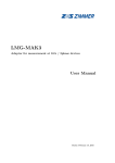
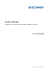
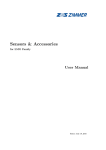
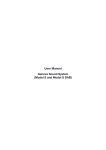
1
PCT2000
User Manual
PCT2000
Precision current transducer 2000 A
User Manual
Status: February 23, 2015
©Copyright 2015
ZES ZIMMER Electronic Systems GmbH
Tabaksmühlenweg 30
D-61440 Oberursel (Taunus), FRG
phone +49 (0)6171 628750
fax +49 (0)6171 52086
e-mail: [email protected]
ZES ZIMMER Inc.
phone +1 760 550 9371
e-mail: [email protected]
Internet: http://www.zes.com
No part of this document may be reproduced, in any form or by any means, without the permission
in writing from ZES ZIMMER Electronic Systems GmbH.
Observe copyright notice according to DIN ISO 16016!
We reserve the right to implement technical changes at any time, particularly where these changes
will improve the performance of the product.
2/12
www.zes.com
Manufacturer Declaration
ZES ZIMMER Electronic Systems GmbH certifies herewith that the device to which this declaration
belongs to is in compliance with all specifications contained in the delivered user manual. It has left
the factory in mechanically and electrically safe condition.
The measuring instrument, tools and standards used in production, adjustment and calibration are
calibrated according to ISO 9000 (traceable to national standards) and correspond to the standard of
precision required to maintain the specified uncertainties.
Tabaksmuehlenweg 30
D-61440 Oberursel
Germany
www.zes.com
www.zes.com
3/12
1 Used symbols
This manual describes and explains symbols which are found here and displayed on the equipment.
Observation of these warning signs is required for safe operation.
Electric shock
This symbol indicates danger of injury or death from electric shock due to dangerous voltages. Do
not touch. Use extreme caution.
AC voltages over 33 V RMS, 46.7 V peak and DC voltages over 70 V are deemed to be hazardous live
according to IEC 61010 resp. EN 61010. There is a danger of electric shock. This can cause death or
injury to body or health. Furthermore, there is a risk of material damages.
High temperature
This symbol indicates a high temperature. There is a burn and fire hazard. There is a danger of
fire or injury to body or health due to hot surfaces or material. Furthermore, there can be material
damages to other objects due to contact or close proximity. If a burn or fire does occur, there can be
further damages which can cause death or injury to body or health.
Caution
This symbol indicates the risk of damages to persons or material. Also if material damages occur,
there can be further damages which can cause death or injury to body or health.
This symbol on the equipment indicates that this user manual is to be consulted for instruction or
further information provided in order for save operation.
Information
This symbol indicates facts or information regarding the equipment which should be observed for easy
and accurate operation.
Protective conductor terminal
This symbol indicates the terminal for the protective conductor. See also Connection to power
supply and protective conductor [2.1→6].
[→4]
Used symbols
[1→4]
References/links
References to tables, figures, listings, etc. consist of their identifier followed by the book symbol and
the page number.
References to chapters, sections, and subsections consist of the heading of the section and the sectional
number followed by the book symbol and the page number.
In the PDF version of this document, one can click on any of these reference elements to jump to the
reference.
2 Safety recommendations
This equipment was designed according to IEC 61010 and EN 61010 and has left the factory in a
mechanically and electrically safe condition. To maintain safe operation, the user must follow the
instructions and warnings contained in this manual. The equipment must only be used for the purposes
described in this manual.
If damage to the equipment is suspected, it must be removed from operation to prevent possible
further damages or injury. In addition the required repair work must be carried out by a trained
technician at a suitable repair facility.
Until shown to be otherwise, the equipment must be considered unsafe to operate if
• there is visual evidence of physical damage,
• it fails to operate correctly,
• the equipment has been heavily overloaded due to to high currents (short circuit or something
similar),
• the equipment has been heavily overloaded due to to high voltages,
• the equipment has been operated with supply voltage outside specifications,
4/12
www.zes.com
• there are loose parts inside the equipment,
• long term storage has taken place in conditions outside the stated specifications for safe storage,
• condensation is present, or
• rough transport has occurred.
The intended use of this equipment (within the limitations stated in the the technical data) is to
measure electrical current and/or voltage.
When handling electricity and/or an electrical apparatus, be sure to observe all safety rules. These
rules include, but are not limited to, the following:
• Opening the equipment exposes components which are under high voltage.This is only permitted
to trained personnel. User risks injury by removing cover and may void any manufacturer’s
warranty. All voltage sources must be disconnected from the equipment before any equipment
covers are removed. Only suitably qualified personnel are permitted such access for the purpose
of calibration, service, repair or changing of components.
If the equipment has been opened, a high voltage test and a test of the protective conductor are
necessary according EN 61010 following the closing of the equipment for safety purposes prior
to use.
• Fuses may only be replaced with the correctly rated and recommended types as written in this
manual. Reading the rated values from the fuse to be replaced is not permitted. The use of
repaired, short-circuited or insufficient fuses is not permitted.
• The environmental conditions (see General environmental conditions [3→8]) must be
observed to ensure safe operation of the equipment.
Use in any type of wet or explosive environment or in presence of flammable gases or liquids is
especially prohibited.
• The equipment and accessories (such as wires and clips) must be checked before each use.
Defective parts must be replaced.
• Ventilation openings must be kept clear (see General environmental conditions [3→8])
to guarantee the required air flow and to prevent overheating of the equipment. In the same
way, the air filter at the air inlets must be clean to permit sufficient air flow. Do not operate
the equipment without air filter or the filter holder as injury may result.
Especially take care that the equipment is not placed above sheets of paper which could get
sucked into the ventilation openings at the bottom of the equipment!
When mounting the equipment into a rack, make sure that the slide rails do not cover any
ventilation openings.
• The equipment must not be used in a medical environment nor in any other environment that
may have a potential effect on life or health.
• Impacts or rough handling may damage the equipment. Do not place heavy objects on the
equipment.
• If the weight of the equipment is too heavy to be carried by one person, carry the equipment
with two persons and/or use an appropriate tool. In all cases, use the handles and grips of the
equipment to lift and carry it safely.
• The equipment is not designed to detect hazards or similar! A wrong reading (e.g. by choosing
a wrong filter or range) could give you the wrong impression of a safe state. Use appropriate
tools (e.g. a voltage detector) instead of this equipment to detect dangerous situations.
• Be careful when connecting external equipment like an external keyboard or mouse to an
instrument. They might not be designed to operate in the same EMC environment as the
instrument and therefore they could be disturbed. This could lead to unwanted operation of the
instrument like changing ranges or something similar.
www.zes.com
5/12
• When connecting the instrument watch the order of connections: First connect it to
the protective conductor and the power supply (see Connection to power supply
and protective conductor [2.1→6]), then connect it to the measurement circuit (see
Connection to measurement circuit [2.2→6]). Then switch on the instrument and the
equipment, and finally, after double checking the wiring, switch on the measurement circuit.
• This equipment was designed according to IEC 61010 and EN 61010 which are general safety
standards for equipment for measurement, control and laboratory use. In a concrete application
or environment further safety standards might be applicable and have to be regarded in addition.
2.1 Connection to power supply and protective conductor
• Before connecting the mains cable to the power supply, confirm that the mains supply voltage
corresponds to the voltage printed on the model’s identification plate. If a voltage selector
switch exists, it must be set appropriately. A suitable power source has to be used to operate
the equipment/instrument.
• The mains plug may only be inserted into a mains power supply socket with protective earth
contact. This protection must not be disabled by the usage of plugs, cables or extension cords
without protective earth.
The mains plug must be inserted into the mains socket before any other connections are made to
the equipment/instrument. Any kind of interruption of the protective earth, inside or outside the
equipment/instrument, or disconnecting the protective earth connector can result in an unsafe
condition of the equipment/instrument and is not allowed. The usage of cables, plugs, sockets
or adapters with only two poles, prongs or connectors is not allowed.
The additional protective conductor terminal of the equipment/instrument chassis must be used
for the case where an earth current in excess of 10 A might result accidentally from the circuit
under test.
Such currents are too large for the earthing connection of the equipment/instrument’s
supply cord. In case of a single fault, the protective conductor might not be able to
carry this current. If it would be interrupted, the case would no longer be protected
against electric shock!
In this case, connect the additional protective conductor terminal with an adequately rated cable
to a suitable earthing point. The additional protective conductor terminal is limited to currents
up to 32 A.
If reliable earthing cannot be realized, the connections between the circuit under test and the
equipment/instrument must be fused appropriately.
The earth terminal on the equipment/instrument must not be used as the only earth
connection for the equipment/instrument nor must the circuit under test nor any other
equipment/instrument be earthed by this terminal. The additional protective conductor is
marked with following symbol:
2.2 Connection to measurement circuit
• Remove all energy sources from the measurement circuit before making any connections between
this circuit and the analyzer. Do not connect or disconnect any cables while they are carrying
voltage relative to earth.
• Use only measurement cables with safety connectors and sufficient cross section. Be sure that
the cables have a sufficient voltage and current rating and are usable for the desired overvoltage
and measurement category.
6/12
www.zes.com
Cables not having safety but standard connectors might have insufficient clearance and
creepage distances, even if they are plugged into the socket. So there is always a risk
of an electric shock.
Use only colored cables which match to the color of the jack to help prevent a wrong connection.
When connecting the measurement circuit, take special care not to connect the voltage wires to
the current input of the equipment/instrument. When switching the measurement circuit on,
this would result in a short circuit which risks damage to the analyzer and to the user!
Such short circuits can be very dangerous, as currents of several thousand amperes
might flow during the short circuit!
For the connection of the voltage measurement circuit to the equipment/instrument use only
cables with suitable fuses, like those delivered together with the equipment/instrument.
The fuses in the voltage measurement cables will interrupt the current flow in case
that these cables are accidentally inserted into the low ohmic current measurement
jacks. Therefore short circuiting of a high power source (e.g. the output of an energy
distribution transformer) will not cause any hazard.
The yellow and black voltage cables have each an implemented fuse. Before and after each
measurement: Check the fuse! To replace this fuse, remove the cable on both sides from all
circuits to make it free of dangerous voltages. Unscrew the fuse holder. Replace the fuse only
with following type:
6.3x32 mm, FF 500 mA, 1000 V, AC+DC, 30 kA breaking capacity
Screw the fuse holder together again.
• When connecting to high power measurement circuits (e.g. the output of an energy distribution
transformer), massive damage could occur when mismatching cables, short-circuiting the
measurement circuit, or using the current jacks of the equipment/instrument instead of the
voltage jacks and similar. So it is recommended to use appropriate fuses in all measurement
cables. When selecting a fuse, ensure that at least the following properties are met:
– The usual measuring current must flow without interruption (rated current of the fuse)
– The short circuit current of the measurement circuit must be interrupted safely (breaking
capacity of the fuse)
– The maximum voltage of the measurement circuit must be interrupted safely (rated voltage
of the fuse)
– The fuse must be suitable for the type of current: AC, DC or both (breaking capacity of
the fuse)
– The fuse must be fast enough to protect the cables and the equipment/instrument
• The maximum voltages between the voltage jacks may not exceed the technical specifications.
• The maximum currents at the current jacks may not exceed the technical specifications.
• The maximum voltages of the jacks against earth may not exceed the technical specifications.
• External current sensors or transformers must be connected to wires and jacks which have a
ten times higher overload capability, only. If the cables or jacks are not sufficient they could be
interrupted in case of overload! For the same reason it is not allowed to use fuses in this current
measurement wires.
Before using jacks, test if they have a low impedance current path to prevent high voltages at
the output of the external device.
In general, it is dangerous to interrupt the secondary side of a current transformer
as there might appear very high voltages which could lead to electric shock.
www.zes.com
7/12
• Cables from/to external sensors are usually designed to operate with low voltages (e.g <15 V).
When using these in an environment with a high voltage circuit, use caution as further isolation
might be necessary. For the operation itself the isolation is sufficient, but if these cables touch
a bare conductor with dangerous voltages this can cause an unsafe condition! In such cases,
further isolation might be necessary.
For example, the secondary cables of a current clamp have a very low voltage, but they could
touch the current bar which has a dangerous voltage against earth.
• Especially when establishing external connections, special care must be taken to prevent
electrostatic discharge.
• Different sensors might require different connection cables to the instrument. When changing a
sensor, please ensure that a correct cable is used. Usually the cable is dedicated to a sensor.
• Keep away from energized measurement circuits to prevent electric shock. When performing
measurements on installations or circuits, please observe all safety regulations and guidelines.
In particular, only suitable measurement accessories should be used. Only suitably qualified
personnel are permitted to work with energized measurement circuits.
• When you put the equipment/instrument out of operation, all external cables shall be removed.
Special care has to be taken when disconnecting current sensors. Before interrupting their
secondary current, the primary current has to be switched off. After disconnecting, the secondary
side of the current sensors has to be short-circuited to prevent dangerous voltages.
3 General environmental conditions
The general environmental conditions, except limited or extended by a specific sensor, are:
• Indoor use only
• Altitude up to 2000 m
• Temperature 5 ℃ to 40 ℃
• Maximum relative humidity 80 % for temperatures up to 31 ℃ decreasing linearly to 50 % relative
humidity at 40 ℃
• Mains supply voltage fluctuations up to ±10 % of the nominal voltage
• Transient overvoltages up to the levels of overvoltage category II, i.e. to be supplied from a
power outlet of the building wiring
• Temporary overvoltages occurring on the mains supply
• Pollution degree 2, i.e. only non-conductive pollution occurs except that occasionally a
temporary conductivity caused by condensation is expected
4 Technical assistance
For technical assistance you can contact the supplier of the equipment/instrument or the
manufacturer:
ZES ZIMMER Electronic Systems GmbH
Tabaksmühlenweg 30
D-61440 Oberursel
Germany
Phone: +49 (0)6171/628750
Fax: +49 (0)6171/52086
Email: [email protected]
URL: http://www.zes.com
8/12
www.zes.com
5 Precision current transducer 2000A (PCT2000)
Figure 1: PCT2000
Figure 2: PCT2000 mechanical dimensions
5.1 Safety warnings
• Always connect the sensor first to the meter and afterwards to the device under test.
• Attention: when using busbar without isolation regard DSUB cable isolation or aviod contact!
• Please refer to chapter Safety recommendations [2→4]!
www.zes.com
9/12
5.2 Specifications
Nominal input current rms
Maximum input current rms
Maximum input current peak
Transformation ratio
Maximum input overload
Bandwidth
Burden
Safety standard
Rated isolation voltage rms, reinforced isolation
Rms voltage for AC isolation test, 50/60 Hz,
1 min
between primary and (secondary and shield)
between secondary and shield
Impulse withstand voltage
Creepage distance
Comparative Tracking Index
Operating temperature
Storage temperature
Weight
Supply
EMC
2000 A
3000 A
3000 A
1500:1
10 kA (100 ms)
10 kHz
0 … 1Ω
EN 61010-1
1600 V CAT II, pollution degree 2
9.8 kV
200 V
20 kV
22 mm
CTI 600
-40 ℃ … 65 ℃
-40 ℃ … 65 ℃
4.5 kg
±(15 V±0.75 V)
2.1 A
EN 61326-1
Figure 3: PCT2000 temperature derating of input current vs. frequency and temperature
Figure 4: PCT2000 typical gain error vs. frequency
10/12
www.zes.com
Figure 5: PCT2000 typical phase error vs. frequency
5.3 Installation
Grounding the transducer head is strictly recommended! Even if there is no requirement for safety
ground on the product, for safety reasons the transducer head PCT2000 is strictly recommended to
be connected to earth ground! If in case of damage in the installation a bare conductor connects
the aluminium housing this will prevent the transducer head and the LMG connection cable to be
energised. Connect the earth wire to the transducer head PCT2000 using a ring terminal and a
toothed locked washer designed for the maximun short circuit current of the installation, fastened to
one of the 6.5 mm mounting holes. Grounding of the transducer head PCT2000 is also recommended
to lead away capacitive coupled distortion.
Also if bare conductors can be used up to the above values, it is strictly recommended to use
isolated conductors only. By this is prevented, that the housing of a transducer might short circuit
two conductors. Further more there are no problems when the secondary cable touches a primary
conductor.
Do not power up the device before all cables are connected!
Connect a DSUB cable between supply unit and the sensor. Available cable lengths are: 2m, 5m and
10m.
Connect an instrument with low impedance current path on the secondary output (4mm red and black
connectors).
When all connections are secured - connect mains power. When mains is applied a green light diode
at the front next to symbol ’power’ will light green. For each sensor connected a green light diode will
light on the front if the connection is correct and the sensor is operating within normal range.
5.4 Uncertainty
The uncertainties are based on: sinusoidal current, ambient temperature 23±3 ℃, calibration interval
1 year, conductor in the middle of the transducer.
Frequency
DC … 500 Hz
500 Hz … 1 kHz
1 kHz … 10 kHz
Amlitude uncertainty
in % of nominal input current rms
±0.01 %
±0.01 %
±2.5 %
Phase uncertainty
±0.04 °
±0.4 °
±2.5 °
Temperature coefficient ±0.1 ppm/℃ of maximum input current peak in the temperature range of
-40 ℃ … +65 ℃ .
www.zes.com
11/12
5.5 Sensor without supply or open secondary circuit
Both AC and DC primary current can be applied up to 100 % of nominal current under following
conditions:
• Sensor is unpowered and secondary circuit is open
• Sensor is unpowered and secondary circuit is closed
• Sensor is powered and secondary circuit is open
• Sensor is powered and secondary circuit is interrupted during measurement
Note that the sensor core will be magnetized in all four cases, leading to a small change in output
offset current.
12/12
www.zes.com