1
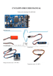
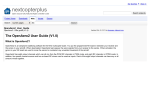
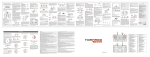
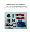
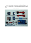
CYCLOPS OSD USER MANUAL 5.0
Thank you for choosing CYCLOPS OSD V5.0
New features: CYCLOPS OSD V5.0 is incorporated with Autopilot function and infrared attitude
sensor capable of controlling aircraft's attitude, and is able to control the aircraft with aileron and
elevator based on preset controlling parameters. This OSD has 8 autopilot waypoints available
apart from the launching point and is able to fully control the aircraft during waypoint autopilot and
home-returning. In addition, the user can set the center , radius, and the direction of circling to
enable the aircraft to fly in circle at certain point. The OSD also features 10HZ GPS module,
compass indicator, modified autopilot program, reduced size and lighter weight.
The OSD consists of several components including:
OSD Main board(18g)
10HZ GPS Module(9.5g)
Voltage and current sensor(50V、100A)
(11g)
Setting board(5g)
Infrared attitude sensor(8g)
Connection diagram
Current sensor connection diagram
Power supply jumper: Connect pin 1 and pin2 to use power battery as the power
supply(the power battery must be 12V or 3S Lipo); connect pin 2 and pin 3 to feed
OSD, camera and video TX with additional 12V power supply.
Current sensor connection diagram
How to use Cyclops OSD
Connect the component according to the above, power it on, and the OSD gives such texts on the
screen.
The GPS starts to search for satellites; the signal strength icon at the right top indicates the
found satellite number. Flashing icon indicates that no satellite is found or the GPS signal is too
weak to be used for positioning (positioning progress will take 1-5 minutes when the GPS signal is
favorable depending on environment.)
Go up and down in the menu by pressing “up” and “down” buttons and press “reset” key in the
middle to confirm.
Menu introduction:
Record MAX:Select to show max flight parameters or not. In case of selecting Y, then if the plan’s
altitude is lower than 20m and velocity is 0, then the OSD will automatically display the max
altitude, max speed, max distance from the launching point and max current of the power battery
that experienced during this flight. In case of selecting N, and you still want to see the max
parameters, hold the “up” button on the board.
Trip:Whether to display the travel distance on the screen
Power BAT:Whether to display the information of power battery on the screen(including voltage,
current and consumed mAh)
Video BAT:whether to display the battery voltage for video TX or cam on the screen
HUD :Whether to display flight information in HUD mode.
ATT data: Whether to display attitude information, P is for pitch and R is for roll.
When the parameter is 0, it indicates the sensor is placed horizontally. When the
parameter is above zero, it indicates the senor is tilting down or right. When the
parameter is below zero, it indicates the senor is tilting up or left.
Reset Current:Current return to zero(unless changing current sensor, only one return to zero
process is needed.)
V/S Alarm:Sinking velocity warning, when the sinking velocity during fly exceeds the set value,
“warn” icon will show up in the middle of screen.
Bat Scale:Set the battery capacity (when the mAh consumed reaches the set capacity value,
capacity digits and icon will flash to warn the pilot).
Return: Return to fly mode
10 seconds after power on, the OSD will enter fly mode:
HUD MODE
Numeral display mode
Coordinate mode (the left is for the current coordinate and the right is for the
coordinate of target point )
Function introduction
In case the readings are deviated from reality, press “reset” button to reset all readings.
If the altitude is lower than 50m, the altitude reading will flash.
If less than 3 satellites were found, or the OSD determines the satellite readings do not reflect the
reality, the satellite number on the top right corner will flash.
If the consumption of power battery reaches the set value, the battery icon and power consumption
digits will flash to warn the pilot.
View angle is detected as below:
The return-to-home icon
represents:turn 23 degrees to the left, 23m away from
the launching point.
Fly direction and current position:
Taking the north as 0 degree, turn 360 degrees clockwise. If the fly direction is west, then the OSD
displays “270”.
The current position of plane is displayed by taking the north as 0 degree, and the launching point
as point of the origin, turn 360 degrees clockwise.
For example, if the plane is at the southeast of the launching point , then OSD will display 135.
Autopilot Menu
Precautions before use
1、Model planes with good stability is preferred
2、 To switch the control mode of OSD, a proportional knob channel on the radio
control should be used. The blue LED lights constantly after powering on and
blinks during autopilot.
From left to right: Manual, PA mode, Way autopilot, automatic home-return.
3. It’s suggested to use radio control system with F/S (failsafe), It's recommended to set the
flight control channel's failsafe to home-return mode. In case losing control during
flight, the OSD will automatically bring the plane back to home.
4、During autopilot, the OSD will display AUTOPILOT on the screen and the radio icon on the
screen will flash. If GPS signal lost during flight, manual control and PA mode can still be
activated, and the "AUTOPILOT" is not displayed; therefore it's very important to
set failsafe (F/S function)of the RC receiver before take-off.
5. The infrared attitude sensor should be installed as much as horizontally on the
aircraft.
6. PA mode is used to stabilize manual control. It can help plane to fly horizontally,
but this mode is not suitable for launching (in PA mode ,the elevator movement is
smaller than in manual control mode) or landing in complex surroundings.
Parameters setup
Double check the wire connection and power on the OSD. Press “up” and “down” button to enter
the setup menu, use “up” and “down” button to go up and down in the menu and switch the
following setup menus.
OSD parameter setup menu
Autopilot parameter setup page1
Autopilot parameter setup page2
Waypoint setup page1
Waypoint setup page2
Waypoint setup page3
Waypoint setup page4
Autopilot setup
Page 1
WEATHER:Different weather mode should be selected for different weather in order
to achieve best autopilot performance. Prior to use, set this parameter to 1, and
point one end of the wing to the ground and the other end to the sky, observe the
parameter, normally the best performance can be achieved when the parameter is
30-43(maximum 43). When the parameter is too small, gradually increase the parameter
(2-5) and observe the parameter according to the above sequence.
SERVO DIR(set correct autopilot direction): determine the correct servo direction during
autopilot. Connect all wires, power on radio and OSD, enter setup menu, set the elevator stick to
lowest position and rudder (when connecting ailerons to rudder in-out on the OSD, pull aileron
stick instead) stick to the very right position, then press the set button, the “OK” will begin to flash,
after the flash finishes, the servo direction then is set. During servo direction determination period,
the LED on autopilot board will flash until the direction is set.
Determine the right servo direction
Taileron :Elevator & aileron mixing selection. When the aircraft is fly wing type,
select "Y" , and turn off the elevator & aileron mixing on the radio controller.
Pitch Trim :Pitch trim for infrared attitude sensor. After installing the infrared
sensor to the model plane, lift the plane above head horizontally and observe the
attitude parameter. For example, if the Pitch is -3, then adjust pitch trim also
to-3. Repeat the above sequence and observe the parameter until it being 0. This
work is only needed to be done once after installation of infrared sensor unless
plane change or re-installation of the sensor.
Roll trim: it should be done with the same way of pitch trim, and adjustment should
be made according to Roll.
MAXHDGCHG (heading correction limit): Determine how aggressive the autopilot will correct
the heading(unit: degree) adjustment:0-180 degree. This parameter means: when the plane needs
to turn, autopilot system will allow more aggressive heading correction to bigger heading error,
but this parameter will still control the maximum heading correction. For example, the
MAXHDGCHG is set to 10 degree, even the heading error is 100 degree, and the autopilot system
would still correction the heading with maximum 10 degree. Suggested value: 15 degree.
SLOPEANGLE:The slope angle during turning. Lift the plane horizontally above the
head and change the roll angle to simulate turning. Observe the roll parameter to
set the suitable slope angle for autopilot. This parameter should be adjusted with
care, and smaller value is recommended (15-20) to avoid altitude dropping. However,
too small value would cause slow turning.
HDGCONTGAIN:Heading deviation correction. When the model plane flies in crosswind
condition, the heading would have a small angle of deviation, and the plane can
not directly fly to the target point. This parameter is used to correct the crosswind
effect. Attention: bigger value means smaller gain, when the crosswind is strong,
this parameter should be decreased. However the value being too low would cause
zigzag flying. Recommended value: 40, and the best value should be determined via
test fly.
AILSEVGAIN:Aileron servo control gain. Recommended value 18. The plane will swing
if this value is too big.
Page 2
CRUISEALT(Cruise altitude): Determine the autopilot altitude (Unit: meter). Range:0-2000m.
In G mode, the plane will return home not lower than set altitude. In E mode, the plane will return
home while trying to maintain the set altitude.
MAXALTCHG (Altitude correction limit): Determine how aggressive the autopilot will act the
altitude error.(Unit: meter) Range:0-50 m. This parameter means: When the plane is under
altitude auto control, more altitude deviation would lead to more aggressive auto altitude
correction. But this parameter determines the maximum correction value. For example ,when this
parameter is set to 30m, even the altitude deviation is 100m, the autopilot would still correct
altitude error with the same servo movement of 30m deviation. Suggested value:10m.
PITCHANGLE:The climb angle of the plane. Lift the plane horizontally in open area,
and simulate the climb angle of the plane to observe the “Pitch” parameter, and
set the suitable value. It’s recommended to keep this parameter small or it would
cause speed loss, too fast turning and even stall. So this value must be kept small.
ALTCONTGAIN:Correction gain for small height deviation. When external disturbance
is causing the plane having small height deviation and unable to go to the set
navigation height, this parameter would help to correction the deviation. Attention:
bigger the value is, lower the correction gain is. When the plane is encountering
big upward or downward air current, decrease this parameter. However, too small
value would cause wavy flight. Recommended value: 40. Adjust this value with test
fly.
ELESEVGAIN: Elevator servo control gain. Recommended value: 50. Too big value
would result in wavy flight.
SPEELDOWLIM(Lowest flying speed): If the speed is lower than this value, then
autopilot will not attempt to climb to the navigation altitude but keep the current
altitude in order to avoid stall. Parameter range: 0-50km/h.
Note: Even the autopilot parameter is set correct; do not conduct test flights in
inclement weather
Waypoint setup
Page1-2
DISTANCE: Distance between waypoint and home(unit: meter). Range:0-10,000m
Angle: Determine the angel between due north and waypoint.(Unit: degree). Range:0-359 degree.
Waypoint coordinate demo
Actual fly track
Page3-4
WAYPOINT A---WAYPOINT H: Whether to use such waypoint.
AUTO WAYPOINT: Auto waypoint switch function. Choose “Y”, the plane will automatically
go to the next waypoint; Choose “N” the plane will fly around the current waypoint until ordered
to go to next waypoint by the 3-stage switch on the radio.
ROUTE CLOSE: determine whether to have closed fly rout. Choose “Y”, the plane will go from
waypoint A-H repeatedly. Choose “N”, the plane will fly from waypoint A-H and return to home.
Spiral Dir: Default hover direction: L = counter-clockwise circling flight, R=
clockwise circling flight.
Spiral Radius: Default hover radius: please set this value according to the turning
performance of the plane. It’s recommended that at least 100m should be the minimum
value.
MAXDISCHG: Maximum waypoint deviation (Unit: meter), Range:0-100m, this parameter
determine how close the plane is to the waypoint till autopilot determine the current waypoint is
reached. This parameter is greatly determined by weather and plane’s performance. Too low value
will make the plane fail to reach the set waypoint. Suggested value:30m
SAVE: Save the waypoint setup parameters.