1
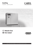
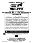
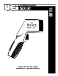
INSTRUCTION MANUAL
UTL260
1-800-547-5740 • Fax: (503) 643-6322
www.ueitest.com • email: [email protected]
Introduction
The UTL260 has all the features and measurement functions that appliance
technicians need. It’s ruggedized and slim compact design makes for easy
one handed use.
Features include
• AC current 2A/20A/200A
• AC/DC voltage 600V
• Resistance 2kΩ
• Audible continuity
• LCD display with MAX reading 1999
• Automatic indication of functions and symbols
• Sample rate: 2 times/sec for digital data
• Backlit display for use in low light application
• Read the safety precautions associated with the equipment being
tested and seek assistance or advice when performing
unfamiliar tasks.
• Keep your fingers away from the test lead metal probe contacts
and bus-bars when making measurements. Always grip the
instrument and test-leads behind the hand guards (molded into
the probes).
• In the event of electrical shock, ALWAYS bring the victim to
the emergency room for evaluation, regardless of the victim’s
apparent recovery. Electrical shock can cause an unstable heart
rhythm that may need medical attention.
International Symbols
Safety Notes
Before using this meter, read all safety information carefully. In
this manual the word "WARNING" is used to indicate conditions
or actions that may pose physical hazards to the user. The word
"CAUTION" is used to indicate conditions or actions that may
damage this instrument.
WARNING!
Exceeding the specified limits of this meter is dangerous and can
expose the user to serious or possibly fatal injury.
• DO NOT attempt to measure any voltage that exceeds 600 volts
with this meter - UEi offers numerous alternatives for measuring
high voltage and current
• Voltages above 60 volts DC or 30 volts AC may constitute a
serious shock hazard
• DO NOT attempt to use this meter if either the meter or the test
leads have been damaged. Send unit in for repair by a qualified
repair facility
• Test leads must be fully inserted prior to taking measurements
• Always turn off power to a circuit (or assembly) under test before
cutting, unsoldering or breaking the current path. Even small
amounts of current can be dangerous
• Always disconnect the live test lead before disconnecting the
common test lead from a circuit
• When measuring high voltage, disconnect the power source before
making test lead connections. Connect the test leads to the meter
first then to the circuit under test. Reapply power
• If any of the following indications occur during testing, turn
off the power source to the circuit under test:
• Arcing
• Flame
• Smoke
• Extreme Heat
• Smell of Burning Materials
• Discoloration or Melting of Components
Controls and Indicators
1. Transformer jaws
2. Protection ring
3. Jaw opening trigger
4. Light key
5. LCD display
6. COM terminal
7.
VΩ terminal
1
8. Power key
9. R o t a ryswitch
10. Hold key
2
10
3
9
4
5
6
UTL260-MAN
8
7
P. 1
LCD Display Functional Description
1. Low battery indication
2. Hold data indication
3. C o n t i n u i tyfunction indication
4. Ohm measurement indication
5. Voltage measurement indication
6. Current measurement indication
7.
DC input indication
8. AC input indication
9. Po l a r i tyindication
1
2
3
(Fig 1)
DC Voltage Measurement
7
4
8
5
9
6
WARNING!
Maximum input voltage of DC V range is 600V DC. Do not attempt to
take any voltage measurement that exceeds 600V DC to avoid electrical
shock and/or damage to the instrument.
1. Set the rotary switch to the 600V “
“ range.
Operating Instructions
2. Connect the black and red test leads to the “COM” and “VΩ”
terminals respectively.
If the current under measurement is higher than the selected value for a
long period, overheating may take place, compromising the safety and
operation of inner circuits.
3. Connect the test leads to the circuit being measured and read
the displayed value (Fig 2).
WARNING!
DO NOT measure currents on high-voltage conductors (>600V) to avoid
risk of discharge and/or incorrect readings.
AC Current Measurement
WARNING!
Make certain that all test leads are disconnected from the
meter terminals.
1. Set the rotary switch to the desired A~range.
2. Clamp the current transducer (jaw) around one of the conductors
under test. Make sure that the clamp jaw is closed (Fig 1).
3. Read the display value.
4. When only the figure “1” is displayed, it indicates over-range
situation and the higher range has to be selected.
(Fig 2)
UTL260-MAN
P. 2
AC Voltage Measurement
WARNING!
Maximum input voltage of AC V range is 600Vrms. Do not attempt to
take any voltage measurement that exceeds 600Vrms to avoid electrical
shock hazard and/or damage to the instrument.
1. Set the rotary switch to the 600V~range.
2. Connect the black and red test leads to the “COM” and “VΩ”
terminals respectively.
3. Connect the test leads to the circuit being measured and read
the displayed value (Fig 3).
(Fig 4)
Continuity Measurement
WARNING!
Before taking any in-circuit resistance measurements, remove power
from the circuit being tested and discharge all capacitors.
1. Set the rotary switch to “
Ω“ range.
2. Connect the black and red test leads to the “COM” and “VΩ”
terminals respectively.
3. Connect the test leads to the resistance in the circuit being
measured (Fig 5).
4. When the test lead to the circuit is below 50Ω, it will be indicated
by a continuous beeping.
NOTE: Continuity test is available to check open/short of the circuit.
(Fig 3)
Resistance Measurement
WARNING!
Before taking any in-circuit resistance measurements, remove power
from the circuit being tested and discharge all capacitors.
1. Set the rotary switch to the 600V~range.
2. Connect the black and red test leads to the “COM” and “VΩ”
terminals respectively.
3. Connect the test leads to the circuit being measured and read
the displayed value (Fig 4).
Short Circuit
Beeper
Open Circuit
UTL260-MAN
(Fig 4)
P. 3
Maintenance
Periodic service
WARNING!
Repair and service of this instrument is to be performed by qualified
personnel only. Improper repair or service could result in physical
degradation of the meter. This could alter the protection from
electrical shock and personal injury this meter provides to the
operator. Perform only those maintenance tasks that you are
qualified to do.
These guidelines will help you attain long and reliable service from
your meter:
WARNING!
Under NO circumstance should you expose batteries to extreme heat or
fire as they may explode and cause injury.
3. Place a fresh 9V battery in the compartment.
NOTE: If you do not plan to use the meter for a month or more,
remove the battery and store it in an area that won’t be damaged by a
leaking battery.
4. Reattach the battery compartment cover to the meter and
reinstall the screw.
Specifications
1. Calibrate your meter annually to ensure it meets original
performance specifications.
2. Keep your meter dry. If it gets wet, wipe it dry immediately. Liquids
damage electronic circuits.
3. Whenever pra c t i cal, keep the meter away from dust and dirt, which
can cause premature wear.
4. Although your meter is built to withstand the rigors of daily use, it
can be damaged by severe impacts. Use reasonable caution when
using and storing the meter.
Cleaning and Decontamination
Periodically clean your meter’s case using a damp cloth. DO NOT use
abrasives, cleaning solvents or strong detergents, as they may damage
the finish or affect the reliability of the structural components.
Environment conditions
Pollution degree
Altitude
Operating temperature
Storage temperature
Max. Voltage between
terminals and earth ground
Operating principal
Sample rate
Display
Range selection
Over range indication
Low battery indication
Battery Replacement
Always use a fresh replacement battery of the specified size and type.
Immediately remove the old or weak battery from the meter and dispose of it in accordance with your local disposal regulations. Old or
defective batteries can leak chemicals that corrode electronic circuits.
WARNING!
To avoid electric shock, be sure to turn off the meter’s power and
disconnect both test leads from any equipment before you remove
or install batteries.
Power source
Polarity indication
Jaw opening diameter
Maximum conductor size
Dimensions
Weight
Accessories
Installation categories II, 600V max. to earth
2
< 2000 m
0˚~40˚C (<80% RH)
-10˚~60˚C (<70% RH, battery removed)
600 V rms
Dual slop integration
2 times/sec for digital data
3-1/2 digits LCD display with max. Reading 1999
Automatic indication of functions and symbols
Manual
LCD will display “1”. If measure value is over
2000V the LCD will display “1” (AC V & DC V range)
The “
“ is displayed when the battery is under
the proper operation range
DC 3VX3, CR2032
“-” displayed automatically
cables 28mm
28mm
194 (L) x 72 (W) x 35 (H) mm
200g. Approx. (battery included)
Manual
Test leads
Carrying case
To install a new battery, follow these procedures:
1. Remove the screw from the battery compartment cover on the
back of the meter and lift the cover.
2. Remove and discard the old battery. Always dispose of old batteries
promptly in a manner consistent with local disposal regulations.
UTL260-MAN
P. 4
Measurement Specifications
*Alignment marks
Audible Continuity
MARK
Range
CONDUCTOR
MARK
Continuity beeper
< approximately 50Ω
Open circuit voltage: less than 700mV
Overload protection: 250V DC or 250V AC rms
MARK
Position the conductor within the jaws at the intersection of the
indicated marks as much as possible in order to meet this meter’s
accuracy specifications.
If the conductor is positioned elsewhere within the jaws, the max.
additional error resulted is 1.5%.
*Accuracy: ±(% of reading + number of digits) at 64˚ to 82˚F (18˚ to
28˚C) with relative humidity to 80%.
AC Current
Range
2A
20A
200A
Resolution
0.001A
0.01A
0.1A
Accuracy
±(2%+5)
Frequency response: 50/60Hz
DC Voltage
Range
600V
Resolution
1V
Accuracy
±(1%+5)
Input impedance: 10MΩ
Maximum input voltage: 600V DC or 600V AC rms
AC Voltage
Range
600V
Resolution
1V
Accuracy
±(1.5%+5)
Input impedance: 10MΩ
Frequency response: 40~400Hz
Maximum input voltage: 600V DC or 600V AC rms
Resistance
Range
2kΩ
Resolution
1Ω
Accuracy
±(1%+5)
Open circuit voltage: less than 700mV
Overload protection: 250V DC or 250V AC rms
UTL260-MAN
P. 5
UTL260
Digital Clamp-On Meter
Limited Warranty
The UTL260 is warranted to be free from defects in materials and workmanship for a period
of one year from the date of purchase. If within the warra n ty period your instrument should
become inoperative from such defects, the unit will be repaired or replaced at UEi’s option.
This warra n ty covers normal use and does not cover damage which occurs in shipment or
failure which results from alteration, tampering, accident, misuse, abuse, neglect or improper
maintenance. Batteries and consequential damage resulting from failed batteries are not
covered by warra n ty.
Any implied warranties, including but not limited to implied warranties of merchantability
and fitness for a particular purpose, are limited to the express warranty. UEi shall not be
liable for loss of use of the instrument or other incidental or consequential damages,
expenses, or economic loss, or for any claim or claims for such damage, expenses or
economic loss. A purchase receipt or other proof of original purchase date will be required
before warra n ty repairs will be rendered. Instruments out of warra n ty will be repaired (when
repairable) for a service charge. Return the unit postage paid and insured to:
1-800-547-5740 • FAX: (503) 643-6322
www.ueitest.com • Email: [email protected]
UTL is distributed by UEi
This warranty gives you specific legal rights. You may also have other rights which vary from
state to state.
PLEASE
RECYCLE
Copyright © 2007 UEi
UTL260-MAN 4/07