1
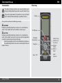
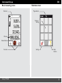
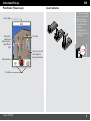
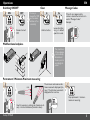
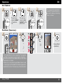
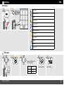
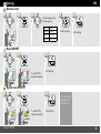
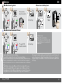
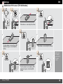
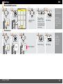
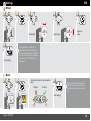
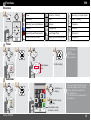
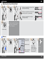
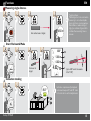
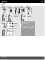
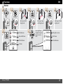
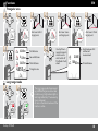
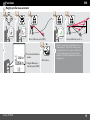
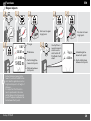
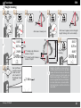
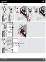
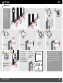
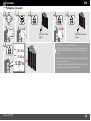
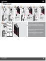
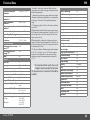
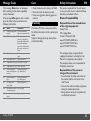
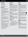
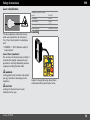
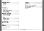
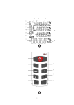
Stanley TLM660 STHT77347 Table of Contents EN -------------------------2 Introduction - - - - - - - - - - - - - - - - - - - - - - - - - - - - - - - - - - - 2 Overview - - - - - - - - - - - - - - - - - - - - - - - - - - - - - - - - - - - - - 2 Basic measuring screen - - - - - - - - - - - - - - - - - - - - - - - - - - - - 3 Selection screen- - - - - - - - - - - - - - - - - - - - - - - - - - - - - - - - - 3 Pointfinder (Viewscreen)- - - - - - - - - - - - - - - - - - - - - - - - - - - 4 Insert batteries - - - - - - - - - - - - - - - - - - - - - - - - - - - - - - - - - 4 Instrument Set-up Operations - - - - - - - - - - - - - - - - - - - - - - - - - - - - - - - - - 5 Switching ON/OFF - - - - - - - - - - - - - - - - - - - - - - - - - - - - - Clear - - - - - - - - - - - - - - - - - - - - - - - - - - - - - - - - - - - - - - - Message Codes - - - - - - - - - - - - - - - - - - - - - - - - - - - - - - - - Multifunctional endpiece - - - - - - - - - - - - - - - - - - - - - - - - - - Permament / Minimum-Maximum measuring- - - - - - - - - - - - Add / Subtract - - - - - - - - - - - - - - - - - - - - - - - - - - - - - - - - Pointfinder (Viewscreen)- - - - - - - - - - - - - - - - - - - - - - - - - - - 5 5 5 5 5 6 6 Settings - - - - - - - - - - - - - - - - - - - - - - - - - - - - - - - - - - - - 7 Overview - - - - - - - - - - - - - - - - - - - - - - - - - - - - - - - - - - - - - 7 Tilt units - - - - - - - - - - - - - - - - - - - - - - - - - - - - - - - - - - - - - - 7 Distance units - - - - - - - - - - - - - - - - - - - - - - - - - - - - - - - - - - 8 Beep ON/OFF - - - - - - - - - - - - - - - - - - - - - - - - - - - - - - - - - 8 Digital level ON/OFF - - - - - - - - - - - - - - - - - - - - - - - - - - - - - 8 De-/Activate keylock - - - - - - - - - - - - - - - - - - - - - - - - - - - - - 9 Switch on with keylock - - - - - - - - - - - - - - - - - - - - - - - - - - - - 9 De-/Activate Bluetooth Smart - - - - - - - - - - - - - - - - - - - - - - - 9 Calibration of tilt sensor (Tilt Calibration) - - - - - - - - - - - - - - 10 Personalized favorites - - - - - - - - - - - - - - - - - - - - - - - - - - - - 11 Illumination - - - - - - - - - - - - - - - - - - - - - - - - - - - - - - - - - - - 11 Offset- - - - - - - - - - - - - - - - - - - - - - - - - - - - - - - - - - - - - - - 12 Reset - - - - - - - - - - - - - - - - - - - - - - - - - - - - - - - - - - - - - - - 12 --------------------------------Overview - - - - - - - - - - - - - - - - - - - - - - - - - - - - - - - - - - - Timer - - - - - - - - - - - - - - - - - - - - - - - - - - - - - - - - - - - - - - Calculator - - - - - - - - - - - - - - - - - - - - - - - - - - - - - - - - - - - Adjusting measuring reference/tripod - - - - - - - - - - - - - - - - - Functions Stanley TLM660 13 13 13 13 14 Memory- - - - - - - - - - - - - - - - - - - - - - - - - - - - - - - - - - - - - - 14 Measuring single distance - - - - - - - - - - - - - - - - - - - - - - - - - - 15 Smart Horizontal Mode - - - - - - - - - - - - - - - - - - - - - - - - - - - 15 Inclination tracking- - - - - - - - - - - - - - - - - - - - - - - - - - - - - - - 15 Area - - - - - - - - - - - - - - - - - - - - - - - - - - - - - - - - - - - - - - - - 16 Volume - - - - - - - - - - - - - - - - - - - - - - - - - - - - - - - - - - - - - - 17 Triangular area - - - - - - - - - - - - - - - - - - - - - - - - - - - - - - - - - 18 Long range mode - - - - - - - - - - - - - - - - - - - - - - - - - - - - - - - 18 Height-profile measurement - - - - - - - - - - - - - - - - - - - - - - - - 19 Sloped objects - - - - - - - - - - - - - - - - - - - - - - - - - - - - - - - - - 20 Height tracking - - - - - - - - - - - - - - - - - - - - - - - - - - - - - - - - - 21 Trapezium - - - - - - - - - - - - - - - - - - - - - - - - - - - - - - - - - - - - 22 Stake out - - - - - - - - - - - - - - - - - - - - - - - - - - - - - - - - - - - - - 23 Pythagoras (2-point) - - - - - - - - - - - - - - - - - - - - - - - - - - - - - 24 Pythagoras (3-point) - - - - - - - - - - - - - - - - - - - - - - - - - - - - - 25 Technical Data - - - - - - - - - - - - - - - - - - - - - - - - - - - - 26 Message Codes - - - - - - - - - - - - - - - - - - - - - - - - - - - - 27 Care - - - - - - - - - - - - - - - - - - - - - - - - - - - - - - - - - - - - - - - 27 Warranty - - - - - - - - - - - - - - - - - - - - - - - - - - - - - - - - - - 27 Safety Instructions - - - - - - - - - - - - - - - - - - - - - - - - 27 Areas of responsibility - - - - - - - - - - - - - - - - - - - - - - - - - - - - 27 Permitted use - - - - - - - - - - - - - - - - - - - - - - - - - - - - - - - - - - 28 Prohibited use - - - - - - - - - - - - - - - - - - - - - - - - - - - - - - - - - 28 Hazards in use - - - - - - - - - - - - - - - - - - - - - - - - - - - - - - - - - 28 Limits of use - - - - - - - - - - - - - - - - - - - - - - - - - - - - - - - - - - - 28 Disposal- - - - - - - - - - - - - - - - - - - - - - - - - - - - - - - - - - - - - - 28 Electromagnetic Compatibility (EMC) - - - - - - - - - - - - - - - - - 28 FCC statement (applicable in U.S.) - - - - - - - - - - - - - - - - - - - 29 Use of the product with Bluetooth® - - - - - - - - - - - - - - - - - - 29 Laser classification - - - - - - - - - - - - - - - - - - - - - - - - - - - - - - - 30 Labelling - - - - - - - - - - - - - - - - - - - - - - - - - - - - - - - - - - - - - 30 1 Instrument Set-up Introduction EN Overview The safety instructions and the user manual should be read through carefully before the product is used for the first time. The person responsible for the product must ensure that all users understand these directions and adhere to them. Display The symbols used have the following meanings: WARNING Indicates a potentially hazardous situation or an unintended use which, if not avoided, will result in death or serious injury. CAUTION Indicates a potentially hazardous situation or an unintended use which, if not avoided, may result in minor injury and/or appreciable material, financial and environmental damage. Important paragraphs which must be adhered to in practice as they enable the product to be used in a technically correct and efficient manner. i Stanley TLM660 On/Measure Pointfinder (Viewscreen) Navigation Selection keys linked to symbols above Function screen Return / Equal Clear / Off Add / Subtract 2 Instrument Set-up Basic measuring screen Status bar EN Selection screen Page indicator FUNC Function / Settings Main line Active function Favorites Stanley TLM660 Settings Help function 3 Instrument Set-up Pointfinder (Viewscreen) EN Insert batteries i Zoom stage 1x Illumination adjustment with navigation keys left and right Active function Crosshair To ensure a reliable use, do not use zinccarbon batteries. We recommend using high quality batteries. Change batteries when battery symbol is flashing. Zoom (1x, 2x, 4x) with navigation keys up and down Favorites Stanley TLM660 4 Operations Switching ON/OFF ON EN Clear OFF i 2 sec 1x If no key is pressed for 180 sec, the device switches off automatically. Device is turned OFF. Message Codes 2x If the info icon appears with a number, observe the instructions in section "Message Codes". Example: Leave actual function, go to default operation mode. Undo last action. Multifunctional endpiece i The orientation of the endpiece is automatically detected and the zero point is accordingly adjusted. Permament / Minimum-Maximum measuring min. 1 max. 2 The minimum and maximum distance measured is displayed (min, max.). The last value measured is displayed in the main line. 2 sec Stops permanent / minimummaximum measuring. Used to measure room diagonals (maximum values) or horizontal distance (minimum values) Stanley TLM660 3 8.532 m 5 Operations Add / Subtract EN 2x 1 2 7.332 m 3 The next measurement is added to the previous one. The next measurement is subtracted from the previous one. i 4 7.332 m This process can be repeated as required. The same process can be used for adding or subtracting areas or volumes. 20.179 m 12.847 m Pointfinder (Viewscreen) 4x 1x 1 4x 1x 2 3 4 2x 2x 1x i 1x Exit pointfinder (viewscreen). This is a great help for outdoor measuring. The integrated pointfinder (viewscreen) shows the target on the display. The device measures in the middle of the cross hair, even if the laser dot is not visible. Parallax errors occur when the pointfinder camera is used on close targets, with the effect that the laser appears displaced in the crosshair. In this case rely on the real laser dot. Stanley TLM660 6 Settings Overview EN Tilt units 1 2 Distance units Beep Digital level Keypad lock Bluethooth® Tilt calibration Favorites Illumination Offset Reset Information Tilt units 1 2 3 Switch between the following units: 360.0° 0.00 % ± 180.0° 0.0 mm/m ± 90.0° 0.00 in/ft Stanley TLM660 4 5 Confirm setting. Exit settings. 7 Settings Distance units 1 EN 2 3 Switch between the following units: 0.00 m 0.000 m 0.0000 m 0.0 mm 4 0.00 ft 0.00 in 0 1/32 in 0'00" 1/32 5 Confirm setting. Exit settings. Beep ON/OFF 1 2 3 Exit settings. To switch ON, repeat procedure. OFF ON Digital level ON/OFF 1 2 To switch ON, repeat procedure. ON Stanley TLM660 i 3 The digital level is displayed in the status bar. Exit settings. OFF 8 Settings De-/Activate keylock 1 EN Switch on with keylock To deactivate, repeat procedure. 2 3 1 2 within 2 sec Exit settings. ON OFF De-/Activate Bluetooth Smart 1 2 To switch ON, repeat procedure. ON i i 3 Exit settings. OFF Switch on Bluetooth Smart in Settings. Connect the device with your smart phone, pad, laptop,… The actual measurement is transferred automatically if Bluetooth connection is established. To transfer a result from the main line, press =. Bluetooth switches off as soon as the laser distance meter is switched off. The efficient and innovative Bluetooth Smart module (with the new Bluetooth standard V4.0) works together with all Bluetooth Smart Ready devices. All other Bluetooth devices do not support the energy saving Bluetooth Smart Module, which is integrated in the device. Stanley TLM660 Default mode: Bluetooth is switched on. Bluetooth icon in status line is displayed if device is connected with Bluetooth. We accept no liability whatsoever arising from the use of the free software and we are not obliged to provide corrections nor to develop upgrades. Apps for Android® or Mac iOS can be found in special internet shops. 9 Settings Calibration of tilt sensor (Tilt Calibration) 1 2 EN 3 4 180° Place device on absolutely flat surface. 180° 5 6 7 Turn the device horizontally by 180° and place it again on absolutely flat surface. 8 Place device on absolutely flat surface. 9 180° 180° 10 i After 2 sec the device goes back to the basic mode. Turn the device horizontally by 180° and place it again on absolutely flat surface. Stanley TLM660 10 Settings Personalized favorites EN Favorite 1 2 3 4 Press selection key left or right. Function is set as favorite above the corresponding selection key. Select favorite function. i 5 Select your favorite functions for quick access. Short cut: Press 2 sec on a selection-key in the measuring mode. Exit settings. Illumination 1 2 3 1/6 Stanley TLM660 4 1/6 2/6 3/6 4/6 5/6 6/6 i 5 Confirm setting. Exit settings. To save power reduce brightness if not necessary. Select brightness. 11 Settings Offset 1 EN 2 3 4 Select digit. i 6 Exit settings. 1.012 m 5 1.012 m Adjust digit. Approve value. An offset adds or subtracts a specified value automatically to or from all measurements. This function allows tolerances to be taken into account. The offset icon is displayed. Reset Second confirmation with selection keys: 1 2 3 Refuse: Confirm: i 4 Reset returns the instrument to the factory settings. All customized settings and memories are lost. Exit settings. Stanley TLM660 12 Functions Overview EN Timer Inclination Tracking Measuring on sloped objects Calculator Area Height Tracking Adjusting measuring reference Volume Trapezium Memory Triangle area Stake out Single Distance Measurement Long Range Mode Pythagoras 1 Smart Horizontal Mode Height-profile Measurement Pythagoras 2 Timer 1 2 3 i 4 30 sec 5 sec 2 sec Off Select release time. The self release starts if ON/Measure key is pressed. Confirm setting. Calculator 1 2 Select key on display. 3 Confirm every key. C/CE Stanley TLM660 = i The measurement result from the main line is taken over to the calculator and can be used for further calculations. Ft/in fractions are converted into ft/in decimal. Use selection keys for clear or result. 13 Functions Adjusting measuring reference/tripod 1 2 3 EN Distance is measured from the rear of the device (standard setting). Distance is measured from the front of the device (lock symbol = permanently). Distance is measured from the tripod thread permanently. i 4 If device is switched off, reference goes back to standard setting (rear of the device). Confirm setting. Memory 1 2 3 12.208 m 6.554 m 23.8899 m 8.449 m Stanley TLM660 Switch between measurements. 4 Delete memory. Take over value for further actions. Use Up/Down navigation keys to show more detailed results of the specific measurement. i Short cut 14 Functions Measuring single distance 1 2 EN 3 i 4 8.532 m Aim active laser at target. Target surfaces: Measuring errors can occur when measuring to colourless liquids, glass, styrofoam or semi-permeable surfaces or when aiming at high gloss surfaces. Against dark surfaces the measuring time increases. Smart Horizontal Mode 2 3 4 5.204 m 0.032 m 4.827 m Aim laser at target. x y z x y 40.8 ° 1 z (up to 360° and a transverse tilt of ±10°) Inclination tracking 1 2 3 89.3° i Inclination is permanently displayed. Instrument beeps at 0° and 90°. Ideal for horizontal or vertical adjustments. 90° 0° Stanley TLM660 15 Functions Area 1 EN 2 3 4 5 Aim laser at first target point. 6.228 m 6 3.9I0 m 20.276 m 24.352 m 2 Stanley TLM660 First distance Second distance Circumference Aim laser at second target point. i The result is shown in the main line and the measured value above. Partial Measurements / Painter function: Press + or - before starting the first measurement. Measure and add or subtract distances. Finish with =. Measure 2nd length. Area 16 Functions Volume 1 EN 2 3 4 Aim laser at first target point. 5.744 m 8 Second distance 2.431 m Third distance 32.653 m 3 Stanley TLM660 6 7 Aim laser at second target point. First distance 2.338 m 5 9 Use Up/Down navigation keys to show more results. Aim laser at third target point. 2 13.430 m 2 Ceiling/floor area 39.300 m Wall areas 16.164 m Circumference Volume 17 Functions Triangular area 1 EN 2 3 4 5 Aim laser at second target point. Aim laser at first target point. 8 4.248 m First distance 4.129 m Second distance 2.425 m Third distance 4.855 m 2 6 9 Use Up/Down navigation keys to show more results. Switch off Pointfinder if activated. 7 Aim laser at third target point. 33.60° 10.802 m Angle between first and second measurement Circumference Triangular area Long range mode 1 Stanley TLM660 2 i The long range mode allows measuring of difficult targets in unfavorable conditions e.g. bright ambient light or bad target reflectivity. The measuring time is increased. An icon in the status line shows if the function is active. 18 Functions Height-profile measurement 1 2 EN 3 4 3 1 0 REF REF 0.054 m Stanley TLM660 i 7 2.042 m h d Aim at additional points 1-x. 2x d 2 h 0 Aim at reference point (REF). 6 5 4 5 Horizontal distance to device Exit function. Ideal for measuring of height differences to a reference point. Can be also used to measure profiles and terrain sections. After measuring the reference point, the horizontal distance and height is displayed for each following point. Height difference to reference point (REF). 19 Functions Sloped objects 1 2 EN 3 4 5 Aim laser at upper target point. 11.00 ° 30.367 m -3.440 m 6 5.452 m i P2 angle P2 distance Vertical height between both points 7 Aim laser at lower target point. Use Up/Down navigation keys to show more results. Switch off Pointfinder if activated. 39.10 ° -4.230 m Included angle between both points Horizontal distance between both points Distance between both points Indirect distance measuring between 2 points with additional results. Ideal for applications such as length and slope of roof, height of chimneys,… It is important, that the instrument is positioned in the same vertical plane as the 2 measured points. The plane is defined of the line between the 2 points. Stanley TLM660 20 Functions Height tracking EN Px Px 1 2 3 4 5 P0 P0 Aim laser at upper points and angle/ height tracking starts automatically. Aim laser at lower point. Px -10.55 ° P0 29.89 ° 3.475 m y x 6.271 m -10.55 ° 7 = Tracking angle if device is turned on tripod = Tracking height if device is turned on tripod z y 6 Stops height tracking. 6.271 m 44.80 ° 8.478 m P0 8 Stanley TLM660 Use Up/Down navigation keys to show more results. Switch off Pointfinder if activated. i 7.160 m z Heights of buildings or trees without suitable reflective points can be determined. At the bottom point, distance and tilt is measured - which needs a reflective laser target. The upper point can be targeted with the pointfinder / crosshair and does not need a reflective laser target as only the inclination is measured. 21 Functions Trapezium 1 EN 2 3 4 Aim laser at upper point. h y 70.80° 5.790 m 7 Stanley TLM660 Use Up/Down navigation keys to show more results. Switch off Pointfinder if activated. x h y 13.459 m 16.440 m Aim laser at 2nd point. x 6 5 78.383 m2 20.9 ° Trapezium area 22 Functions Stake out i EN Two different distances (a and b) can be entered to mark off defined measured lengths. a=b 1 1 2 3 a 2 1 2 b a b 3 4 1.012 m Select digit. 7 8 Approve value "b" and start measurement. Stanley TLM660 5 Adjust digit. Move device slowly along the stake-out line. The distance to the next stake out point is displayed. 1.012 m 0.240 m is missing up to next 0.625 m distance. 6 Approve value "a". Next stake out distance 0.625 m 0.240 m Adjust value "b". i 0.625 m When approaching a stake out point to less than 0.1 m the instrument starts to beep. The function can be stopped by pressing the CLEAR/OFF button. 23 Functions Pythagoras (2-point) 1 2 EN 3 4 5 Aim laser at second target. Aim laser at first target. 6 25.133 m 21.383 m 13.207 m Stanley TLM660 i The result is shown in the main line. Pressing the measuring key for 2 sec in the function activates automatically Minimum or Maximum measurement. We recommend to use the pythagoras only for indirect horizontal measuring. For height measuring (vertical) it is more precise to use a function with the inclination measuring. 24 Functions Pythagoras (3-point) 1 2 EN 3 4 Aim laser at first target. 24.298 m 8 21.264 m 23.018 m 20.571 m Stanley TLM660 5 6 Aim laser at second target. i 7 Aim laser at third target. The result is shown in the main line. Pressing the measuring key for 2 sec in the function activates automatically Minimum or Maximum measurement. We recommend to use the pythagoras only for indirect horizontal measuring. For height measuring (vertical) it is more precise to use a function with inclination measurement. 25 Technical Data EN Distance measurement Accuracy at favourable conditions * ± 1.0 mm / ~1/16" *** Accuracy at unfavourable conditions ** ± 2.0 mm / 0.08 in *** Range at favourable conditions * 200 m / 660 ft Range at unfavourable condition ** 80 m / 260 ft **** Smallest unit displayed Power Range Technology 0.1 mm / 1/32 in ™ Ø laser point at distances yes 6 /30 / 60 mm (10 / 50 / 100 m) Tilt measurement Measuring tolerance to laser beam***** ± 0.2° Measuring tolerance to housing***** ± 0.2° Range 360° General * favourable conditions are: white and diffuse reflecting target (white painted wall), low background illumination and moderate temperatures. ** unfavourable conditions are: targets with lower or higher reflectivity or high background illumination or temperatures at the upper or lower end of the specified temperature range. *** Tolerances apply from 0.05 m to 10 m with a confidence level of 95%. With favourable conditions the tolerance may deteriorate by 0.05 mm/m for distances between 10 m to 30 m, by 0.10 mm/m between 30 m and 100 m and by 0.20 mm/m for distances above 100 m. With unfavourable conditions the tolerance may deteriorate by 0.10 mm/m for distances between 10 m to 30 m, by 0.20 mm/m between 30 m and 100 m and by 0.30 mm/m for distances above 100 m. **** after user calibration. Additional angle related deviation of +/- 0.01° per degree up to +/-45° in each quadrant. Applies at room temperature. For the whole operating temperature range the maximum deviation increases by +/-0.1°. Functions Distance measuring yes Min/Max measuring yes Permanent measuring yes Stake-out yes Addition/Subtraction yes Area yes Triangle area yes Volume yes Trapezium yes Painter function (area with partial measurem.) yes Pythagoras 2-point, 3-point Smart Horizontal Mode / Indirect height yes Height-profile measurement yes Inclination tracking yes Sloped objects yes Height tracking yes Memory 30 displays Beep yes Illuminated colour display yes Multifunctional endpiece yes Pointfinder (Viewscreen) 4xZoom Digital Level yes Bluetooth® Smart yes Personalized Favorites yes Laser class 2 Laser type 635 nm, < 1 mW Protection class IP54 Autom. laser switch off after 90 s Autom. power switch-off after 180 s Bluethooth® Smart Bluethooth v4.0 Range of Bluethooth® 10 m Battery durability (2 x AA) up to 5000 measurements Dimension (H x D x W) 149 x 61 x 31 mm 5.9 x 2.4 x 1.2 in Timer yes Long Range Mode yes 209 g / 7.22 oz Calculator yes Weight (with batteries) Temperature range: - Storage - Operation Stanley TLM660 For accurate indirect results, the use of a tripod is recommended. For accurate tilt measurements a transverse tilt should be avoided. i -25 to 70 °C -13 to 158 °F -10 to 50 °C 14 to 122 °F 26 Message Codes Care Safety Instructions If the message Error does not disappear after switching on the device repeatedly, contact the dealer. If the message InFo appears with a number, press the Clear button and observe the following instructions: • Clean the device with a damp, soft cloth. • Never immerse the device in water. • Never use aggressive cleaning agents or solvents. The person responsible for the instrument must ensure that all users understand these directions and adhere to them. Warranty No. Cause 156 Transverse tilt greater Hold the instrument than 10° without any transverse tilt. 162 Calibration mistake Make sure, the device is placed on a absolutely horizontal and flat surface. Repeat the calibration procedure. If the mistake still occurs, contact your dealer. The Stanley TLM has a two-year warranty. For further information on this, contact your dealer. Subject to change (drawings, descriptions and technical data). Responsibilities of the manufacturer of the original equipment: Stanley Tools 701 E. Joppa Road Towson, Maryland 21286 www.STANLEYLASERS.com www.STANLEYTOOLS.com www.STANLEYTOOLS.eu 204 Calculation error Perform measurement again. 240 Data transfer error Repeat procedure. 252 Temperature too high Let device cool down. 253 Temperature too low Warm device up. 255 Received signal too Change target surface weak, measuring time (e.g. white paper). too long 256 Received signal too high Change target surface (e.g. white paper). 257 Too much background light Shadow target area. 258 Measurement outside Correct range. of measuring range 260 Laser beam interrupted Stanley TLM660 Correction Repeat measurement. EN Areas of responsibility The company above is responsible for supplying the product, including the User Manual in a completely safe condition. The company above is not responsible for third party accessories. Responsibilities of the person in charge of the instrument: • To understand the safety instructions on the product and the instructions in the User Manual. • To be familiar with local safety regulations relating to accident prevention. • Always prevent access to the product by unauthorised personnel. 27 Safety Instructions EN Permitted use Hazards in use Disposal • Measuring distances • Tilt measurement • Data transfer with Bluetooth® WARNING CAUTION Prohibited use • Using the product without instruction • Using outside the stated limits • Deactivation of safety systems and removal of explanatory and hazard labels • Opening of the equipment by using tools (screwdrivers, etc.) • Carrying out modification or conversion of the product • Use of accessories from other manufacturers without express approval • Deliberate dazzling of third parties; also in the dark • Inadequate safeguards at the surveying site (e.g. when measuring on roads, construction sites, etc.) • Deliberate or irresponsible behaviour on scaffolding, when using ladders, when measuring near machines which are running or near parts of machines or installations which are unprotected • Aiming directly in the sun Stanley TLM660 Watch out for erroneous measurements if the instrument is defective or if it has been dropped or has been misused or modified. Carry out periodic test measurements. Particularly after the instrument has been subject to abnormal use, and before, during and after important measurements. CAUTION Never attempt to repair the product yourself. In case of damage, contact a local dealer. WARNING Changes or modifications not expressly approved could void the user’s authority to operate the equipment. Limits of use Refer to section "Technical data". The device is designed for use in areas permanently habitable by humans. Do not use the product in explosion hazardous areas or in aggressive environments. i Flat batteries must not be disposed of with household waste. Care for the environment and take them to the collection points provided in accordance with national or local regulations. The product must not be disposed with household waste. Dispose of the product appropriately in accordance with the national regulations in force in your country. Adhere to the national and country specific regulations. Product specific treatment and waste management can be downloaded from our homepage. Electromagnetic Compatibility (EMC) WARNING The device conforms to the most stringent requirements of the relevant standards and regulations. Yet, the possibility of causing interference in other devices cannot be totally excluded. 28 Safety Instructions FCC statement (applicable in U.S.) This equipment has been tested and found to comply with the limits for a Class B digital device, pursuant to part 15 of the FCC Rules. These limits are designed to provide reasonable protection against harmful interference in a residential installation.This equipment generates, uses and can radiate radio frequency energy and, if not installed and used in accordance with the instructions, may cause harmful interference to radio communications. However, there is no guarantee that interference will not occur in a particular installation. If this equipment does cause harmful interference to radio or television reception, which can be determined by turning the equipment off and on, the user is encouraged to try to correct the interference by one or more of the following measures: • Reorient or relocate the receiving antenna. • Increase the separation between the equipment and receiver. • Connect the equipment into an outlet on a circuit different from that to which the receiver is connected. • Consult the dealer or an experienced radio/TV technician for help. Stanley TLM660 EN This device complies with part 15 of the FCC Rules. Operation is subject to the following two conditions: • This device may not cause harmful interference, and • this device must accept any interference received, including interference that may cause undesired operation. This device complies with Industry Canada license-exempt RSS standard(s). Operation is subject to the following two conditions: • This device may not cause interference and • this device must accept any interference, including interference that may cause undesired operation of the device. Cet appareil est conforme à la section 15 des règlements FCC. Son fonctionnement est soumis aux deux conditions suivantes : • cet appareil ne doit pas causer d'interférences nuisibles, et • cet appareil doit accepter toute autre interférence reçue, y compris les interférences pouvant entraîner un fonctionnement non désiré. Ce dispositif est conforme à la norme RSS210 d’Industrie Canada. L’utilisation est sujette aux deux conditions suivantes : • ce dispositif ne pas doit pas être la source d’interférences nuisibles, et • ce dispositif doit accepter toutes les interférences, y compris les interférences pouvant induire des opérations non souhaitées. Use of the product with Bluetooth® WARNING Electromagnetic radiation can cause disturbances in other equipment, in installations (e.g. medical ones such as pacemakers or hearing aids) and in aircraft. It can also affect humans and animals. Precautions: Athough this product conforms to the most stringent standards and regulations, the possibility of harm to people and animals cannot totally excluded. • Do not use the product near petrol stations, chemical plants, in areas with a potentially explosive atmosphere and where blasting takes place. • Do not use the product near medical equipment. • Do not use the product in airplanes. • Do not use the product near your body for extended periods. 29 Safety Instructions EN Laser classification The device produces visible laser beams, which are emitted from the instrument: It is a Class 2 laser product in accordance with: • IEC60825-1 : 2014 „Radiation safety of laser products“ Laser Class 2 products: Do not stare into the laser beam or direct it towards other people unnecessarily. Eye protection is normally afforded by aversion responses including the blink reflex. Maximum peak radiant output power: 0.95 mW Wavelength: 635 nm Pulse duration: >400ps Pulse repetition frequency: 320 MHz Beam divergence: 0.16mrad x 0.6mrad Labelling WARNING Looking directly into the beam with optical aids (e.g. binoculars, telescopes) can be hazardous. CAUTION Subject to change (drawings, descriptions and technical data) without prior notice. Looking into the laser beam may be hazardous to the eyes. Stanley TLM660 30