1
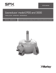
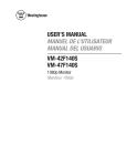
U S E R M A N UA L
comp-ds driveshaft
I N S TA L L AT I O N – O P E R AT I O N – M A I N T E N A N C E
Z0331596 rev A
I S S UE D 0 6 / 2014
R E A D A N D U N D E R S TAN D TH I S M AN UAL P R I O R TO O P E RATI N G OR S E RVI CI N G T H I S PR O D U CT.
parts list
1.22B
1.22C
1.21C
1.22D
1.21A
1.21B
1.22A
1.1
Figure 1
1.0Complete Driveshaft
1.1 Tube and Flange Assembly*
1.2Coupling Assembly (2 required per driveshaft) complete with hub,
flexible-element, cap screws, washers, lock nuts and set screws.
1.21 Hub Assembly
A. Hub
B. Cap Screws (8 required per hub)
C. Set Screws (2 required per hub)
1.22 F
lexible-Element Assembly
A. Flexible Element
B. Cap Screws (4 required per flexible-element)
C. Lock Nuts (4 required per flexible element)
D. Washers (4 required per flexible element)
* E
arlier generations of this driveshaft did not include bonded bushings.
Most parts are still interchangeable. If a tube and flange assembly without
bushings is replaced with a newer version, items 1.22B will also require
replacement.
Note
2
When ordering parts, always provide the cooling tower serial
number and when possible, the driveshaft serial number from a
decal located on the composite tube.
safety and handling
Safety Warning
Warning
Because of the potential for property damage and/or danger to
person(s), it is critical to follow the proper selection, installation
and operating procedures.
Exposed rotating devices are potentially dangerous and can cause
injury or death. They must be guarded in compliance with OSHA,
ANSI and all other local standards for the specific application.
All personnel must follow applicable work safety standards, such
as Lockout/Tagout procedures while working in or around power
transmission devices.
Handling Considerations
1. Marley Comp-DS driveshafts are designed and manufactured to be very
durable and provide years of service if handled properly.
2. Minor aesthetic imperfections, such as surface abrasions, scuffs or small
bumps may be present from manufacturing or handling and will not affect
performance. Heavy, concentrated impacts may cause gouges, penetration
or soft spots in the composite components. If any damage is observed, the
driveshaft should not be placed into service. Only SPX engineering personnel are authorized to approve any issues exceeding the above description
of minor aesthetic imperfections.
3. The entire driveshaft should be inspected periodically or after a strenuous
event such as excessive torque or misalignment, particularly the flexibleelement. Refer to the maintenance section for further information.
4. Unless replacing the flexible-element for maintenance purposes, never remove the cap screws that connect the flexible-element to its adjacent hub.
Factory thread locker will be compromised and the warranty will be voided.
3
installation
General
Marley Comp-DS driveshafts consist of a tube and flange assembly with a
motor and a Geareducer® coupling. Comp-DS driveshafts are dynamically
balanced at the factory as a complete assembly. Flanges and hubs are matchmarked and balanced. Do not change position or relation of match-marked
components during installation. If the tube and flange assembly is replaced the
driveshaft must be rebalanced. It may be performed on the tower by an experienced service contractor or returned to an authorized manufacturing facility.
Warning
All fasteners that connect to the flexible-element must NOT be
over-tightened. If over-tightened, they will become loose over time
and serious property damage and/or injury to person(s) may result.
Refer to Table 2 for torque values.
Installation
Before installing the driveshaft, be sure the motor and Geareducer are on
level bases and their shafts are in reasonable alignment.
1. Note match-mark numbers on the driveshaft flanges and hubs; then remove
the coupling assemblies from either end by removing only the flexible-element
fasteners (1.22B, 1.22C and 1.22D).
Figure 2
Caution
The hub assembly cap screws (8 per hub) that connect the flexible
element to the hub are factory assembled with thread lock compound. They should NOT be loosened or removed when installing
the driveshaft. These hub fasteners are to be removed only when
replacing the flexible-element for maintenance purposes and must
be reinstalled with OEM supplied thread lock compound that is
included in the replacement kit.
2. Remove any burrs or scratches from the motor or Geareducer shafts and
coat both shafts with an anti-seize compound.
3.Insert both keys into their corresponding keyways. Ensure they are fully
seated.
4
installation
Note
Some driveshafts utilizing large bore hubs may come supplied with
a rectangular key. If applicable, the supplied key must be used.
4. Start the driveshaft installation by sliding the couplings (hubs with attached
flexible-element) onto their respective shafts. Slide them onto the shaft ends
with approximately one inch of shaft protrusion through the flexible-element
opening as shown in the Figure 3.
Note
There are some large motor shafts that will not clear the motor end
flexible-element aperture. If this is the case, slide that end on as far
as possible and add another inch of protrusion to the Geareducer
end input shaft exposure.
1.2
1.2
Figure 3
5.Lift the tube and flange assembly into place as shown in Figure 4 and
support approximately level. Ensure flanges are oriented near the correct
hubs (refer to match-marks).
1.1
Figure 4
➠
5
installation
6. Adjust the hub engagement on the Geareducer input shaft so that the hub
hangs off of the shaft approximately 1⁄8" and align match-mark to adjacent
flange match-mark.
Figure 5
7. Insert the four cap screws through the Geareducer end coupling assembly and flange. Ensure the cap screw head is towards the outside of the
driveshaft assembly (i.e. hub side of driveshaft), as shown in Figure 6.
Install the four washers and lock nuts and progressively tighten to the value
specified in Table 2. Do not lubricate these fasteners.
Figure 6
8. Repeat steps 6 and 7 for motor end coupling assembly.
Caution
Note
6
It may be necessary to adjust the method of support initiated in Step
6. Do NOT allow the entire weight of the driveshaft to be cantilever
supported by either coupling at anytime. Flexible-element damage
may result and the warranty will be voided.
If installing motor end flexible-element hardware is challenging,
large-scale misalignment may exist. Symptoms of this scenario
may consist of some or none of the flex-element cap screws easily
sliding through the adjacent flange fastener holes. If this situation
exists, the motor and Geareducer positioning should be adjusted
as necessary.
installation
9. Inspect engagement on both hubs (see Table 1) and ensure that engagement is within tolerance. It may be necessary to adjust the position of the
entire driveshaft assembly. Furthermore, it may be required to slightly modify
the location of the motor to affect the distance between shaft ends.
Hub Engagement
Table 1
Series
Inches
Comp-4
2 ⁄2 + ⁄8 - ⁄4
63.5 +3 - 6
Comp-6
2 ⁄8 + ⁄8 - ⁄4
73.0 +3 -6
END OF MOTOR
OR GEAREDUCER
SHAFT
1
7
1
1
Millimeters
1
1
ENGAGEMENT
END OF HUB
SET SCREW
HUB
TUBE AND FLANGE
ASSEMBLY
FLEX ELEMENT
Figure 7
10. With set-screws backed out, rotate the driveshaft (by hand) a couple of
rotations.
11. Tighten all set-screws. Proceed with alignment procedure.
7
alignment
General
Marley Comp-DS driveshafts are designed to accommodate a certain amount
of misalignment. They must be installed within axial and angular tolerance to
ensure long life and retain the warranty. These two forms of alignment are
independent of one another and correcting one may interfere with the other.
Alignment must be checked at each coupling.
Move motor and/or Geareducer vertically by shimming, or horizontally by
shifting or twisting on support.
Eliminate any large-scale misalignment before proceeding. Then check for
axial alignment to ensure the driveshaft overall length (OAL) isn’t adversely
affected by the hub and/or equipment placement.
Soft Foot: The motor and Geareducer must seat firm and flat against their
respective supports during all alignment inspection(s). If equipment location
is adjusted, the support feet must be secured before rechecking alignment.
Axial Alignment
Special care must be given to the axial hub positioning. If the OAL is effectively too long or short, it will reduce the flexible-element service life. The best
method for avoiding this, is to always ensure the set screw torque is relieved
when adjusting the motor or Geareducer. In other words, never move the
Geareducer or motor axially (closer together or farther apart) after the driveshaft
set screws are tightened.
Angular Alignment
Use a firm and secure means of attaching a dial indicator base to the hub and
align the indicator point to contact the center of a flexible-element cap screw
head (connection point between flex-element and flange). If using a Marley
“Driveshaft Alignment Indicator Kit”, fasten the base of the kit into the tapped
hole, located 90° from the keyway, with the supplied thumbscrew (refer to
Fig. 8). Rotate the driveshaft, by hand, to ensure the dial indicator remains in
contact with the cap screw and that its travel doesn’t “bottom out.”
DIAL INDICATOR
CHAIN-WRAP MOUNT
Figure 8
Marley Driveshaft Alignment Indicator
8
Alternative Alignment Method –
Typical Chain-Wrap Mount
alignment
Check alignment at each end of the driveshaft by rotating the
shaft through 360° noting the total change in the dial indicator
reading. The total indicator reading should not exceed 0.012"
(0.3 mm).
Note
Total indicator reading is the absolute value sum (e.g. +5 and -7
mils readout through one revolution equals 12 mils TIR).
Final
Ensure all fasteners are tight (see Table 2) before placing aligned driveshaft
into service.
– Set Screws
– Cap Screws
– Geareducer Jacking Bolts on Rear Feet (drill holes and use dowel pins,
if necessary)
– Geareducer and Motor Support Bolts
All Comp-DS Series
Fastener
Inch Pounds
Foot Pounds
Newton Meters
Setscrew: ⁄8 -16
240
20
27
Cap Screw: 3⁄8 -16
360
30
40
Cap Screw: 9⁄16 -12
600
50
68
3
Table 2
Torque Values
9
maintenance
General
Inspection of the complete driveshaft should be made every six months.
Marley Comp-DS driveshafts do not require lubrication. If the tube and flange
assembly is replaced, the driveshaft must be rebalanced. It may be performed
on the tower by an experienced service contractor or returned to an authorized
manufacturing facility.
Hardware
Look for corrosion, loose cap screws and set screws. Also check driveshaft
alignment. If as-installed alignment has changed, motor and Geareducer
support hardware should be checked for looseness. If necessary, realign to
within tolerance.
Composite
The tube and flange assembly should be inspected for excessive fiber bloom
and cracks. The flexible-element assembly should be inspected for cracks or
excessive crazing in the urethane as well as any exposed areas of the carbonfiber reinforcement.
Replacing Flexible-Elements
It is recommended to replace the flexible-elements at least every five years
on a preventative maintenance schedule. To do this:
1. Loosen the set screws.
2. Remove the tube and flange assembly.
3. Remove the coupling assemblies.
4. Secure the hub in a vice or something similar and remove the eight hub
cap screws.
Note
Additionally, it is recommended to chase the eight 3/8-16 tapped
holes with a tap to clean out the residual thread locker prior to
installing new flex-element and fasteners.
5.Remove and replace the flexible-element. Be sure to align a flex-element
tab/ear to the hub keyway (see Figures 1 and 2).
6.Re-install the cap screws using the supplied thread locker and torque to
the specified value. See Table 2.
7.Refer to the Installation section within this manual to reinstall and align
driveshaft assembly.
10
comp-ds driveshaft
U S E R M A N UA L
SPX COOLING TECHNOLOGIES, INC.
7401 W 129 ST
OVERLAND PARK, KANSAS 66213 USA
P: 913 664 7400
F: 913 664 7439
[email protected]
spxcooling.com
In the interest of technological progress, all products are subject to design and/or material change without notice.
ISSUED 06/2014
Z0331596 rev A (M2010-1378B)
COPYRIGHT © 2014 SPX Corporation