1
APEX-HPGL User’s Manual
Controller Models HP2 and HP3
Revision 21
Copyright ©1998-2006
Newing-Hall, Inc.
2019 Monroe Street
Toledo, Ohio, 43624
NH Part # 3011001
Last Updated March 2006
This manual is subject to change without notice.
Table of Contents
Chapter 1 - Installation Guide
1.1 Upon Receipt of Shipment……………………………………………………………… 4
1.2 Installing the HPGL Controller…………………………………………………………. 5
1.3 Installing the APEX Product Software………………………………………………... 22
Chapter 2 - Quick Start
2.1 Turning on System Power……………………………………………………………... 23
2.2 System Checkout…………………………………………………………………........ 24
2.3 JLS Software Setup…………………………………………….………………............ 25
2.4 Creating the Work file…………………………………………………………............ 26
2.5 Executing the Work file……………………………………………………………….. 27
Chapter 3 – Operations
3.1 Control Panel Operations……………………………………………………………… 28
3.2 Controller Menu……………………………………………………………………….. 34
3.3 APEX-HPGL Data Cables…………………………………………………………….. 42
3.4 Vector Search Technology (VST)…………………………………………………….. 44
3.5 Tool Changes (Auto/Manual)…………………………………………………………. 46
3.6 Job Server………………………………………………………………………………48
3.7 Distributed Numeric Control (DNC) – Local and Remote……………………………. 51
3.8 Hot Watch……………………………………………………………………………... 54
3.9 Job Queue………………………………………………………………………………58
3.10 Home Positions………………………………………………………………………. 61
Chapter 4 - Software Setup
4.1 Using APEX-JLSTM…………………………………………………………………… 63
4.2 Using CorelDraw TM…………………………………………………………………... 64
4.3 Using CASMate TM……………………………………………………………………. 65
4.4 Using SignLab TM……………………………………………………………………... 66
4.5 Using EngraveLab TM…………………………………………………………………. 67
4.6 Using AutoCAD TM…………………………………………………………………….68
Chapter 5 - HPGL Command Set
5.1 HPGL Command Set…………………………………………………………………...69
5.2 G&M Code Command Set…………………………………………………………….. 73
Chapter 6 – Machine Parameters
6.1 Table Parameters Menu……………………………………………………………….. 75
6.2 Datum Parameters Menu……………………………………………………………….79
6.3 Input/Output Parameters Menu………………………………………………………... 81
6.4 Machine Resolution / Motion Params Menu………………………………………….. 85
6.5 Rates Menu……………………………………………………………………………. 87
6.6 Machine Limits Terminology…………………………………………………………. 89
2
Chapter 7 – Job Previewer
7.1 Operation Overview…………………………………………………………………… 90
Chapter 8 – Job Reporter
8.1 Operation Overview…………………………………………………………………… 92
Chapter 9 – Motion Mechanic
9.1 Operation Overview…………………………………………………………………… 94
Appendix A – Maintenance……………………………………………………………………96
Appendix B – Cable Hook-Up………………………………………………………………... 99
Appendix C – Troubleshooting…………………………………………………………….. 100
Warranty………………………………………………………………………………………... 109
3
Chapter I – Installation
1.1 Upon Receipt of Shipment
Shipping Box
Check the shipping box for damage. If any damage is found, it is important, for insurance
purposes, to indicate this on the freight company's bill of lading before accepting shipment. Call
Newing-Hall's Customer Service at 1-800-521-2615 to report any damage.
Unpacking
Open shipping carton carefully and remove all boxes. DO NOT DAMAGE SHIPPING
CARTONS! Items returned to the factory for service must be shipped in their original containers,
and packed according to applicable instructions provided.
Check the packing list to see that all items have arrived. Call Customer Service if there is a
discrepancy.
4
1.2 Installing the HPGL Controller
Assembly – For Tables without Pedestal
Procedure
1. Unpack the table and place on a secure surface. Remove the plastic tie straps and bridge
block.
2. Unpack the controller from its carton.
3. Two 1-inch nylon set screws are installed diagonally on the controller. Using these setscrews
as guides drop the guides through the controller screw holes on the bracket.
4. Attach two of the button head cap screws (10-32 x 3/8) to the controller and secure using the
Allen wrench.
5
5. Remove both nylon set screws.
6. Attach the remaining button head cap screws (10-32 x 3/8) to the controller and secure using
the Allen wrench.
NOTE: A small magnet is located on the left side of the controller bracket. This magnet is used
to secure the rotary drive when not in use. When attaching the rotary drive use the screws
located in the center of the front drive arm.
Assembly – For Tables with Pedestal (400 or 600)
Remove the APEX-HPGL controller from its carton and carefully place the controller upside
down, facing you, on a stable, protected surface near the engraving table.
6
Locate the controller bracket and align the holes in the bracket with the four (4) tapped holes on
the bottom of the controller. Secure the bracket to the controller making sure that the angle of the
bracket post is toward the rear of the controller.
Assemble the controller arm to the mounting post located to the left rear of the pedestal and
secure it with the lever knob. Attach the controller to the arm and secure it with the remaining
lever knob.
7
Cable Connections
Be sure that the AC power to the HPGL controller and the host computer is OFF before
connecting any cables. Connect the cables as follows:
1. Connect the 9-pin RS232 cable to the HPGL 9-pin serial port on the back of the
controller or use a Ethernet cable to connect to your network or pc (if equipped with an
Ethernet port on the HPGL controller).
2. Connect the remaining end of the 9-pin RS232 cable to the computer's serial port (COM
1 or COM2) if using serial.
3. Connect the 25-pin Motor Driver cable to the HPGL motor driver port on the back of the
controller.
4. Connect the remaining end of the 25-pin Motor Driver cable to the NH engraving table.
5. Connect the free end connector on the end of the rotary motor power cord to the HPGL
rotary motor power connector on the back of the controller.
Note: You can use serial or Ethernet for communications – you can not use both. THE
HPGL CONTROLLER IS SUPPLIED WITH A CROSSOVER NETWORK CABLE. IF
YOU PLAN ON USING THE HPGL CONTROLLER USING A NETWORK WITH A
HUB OR SWITCH YOU MUST USE A STRAIGHT THROUGH NETWORK CABLE.
For tables with Datum sensors fitted …
6. Connect the 15-pin DATUM cable to the HPGL 15-pin DATUM port on the back of the
controller.
7. Connect the remaining end of the 15-pin DATUM cable to the NH engraving table.
8
Note: On current production tables the LED’s are powered through the datum cable.
The LAST step is to connect the standard AC power cord to the HPGL main power connector to
the controller. Connect the remaining end of the power cable to a standard wall outlet.
Installing and Configuring Ethernet
Requirements:
Controllers with Ethernet capability will have an external Ethernet connection on the back of the
controller located above the serial port.
Network Setups:
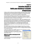
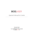
Network setups can be very simple or complex. If you have a network administrator it will be
advisable to seek their expertise. There are a number of ways to attach the HPGL controller to a
network. The first setup uses a hub or switch. Every connection made on the network connects
directly to the hub or switch. The wiring to the hub or switch is a straight through CAT 5 network
cable. The diagram below will illustrate this.
(Using a Hub or Switch)
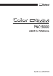
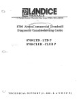
If a network is not present at the location an indirect connection from the computer to the HPGL
controller is possible. This involves one network interface card in the computer or laptop and a
special network cable called a crossover cable that plugs directly into the HPGL controller. A
crossover cable is necessary if you connect two network devices without the use of a hub or switch.
The diagram below will illustrate this:
(Direct Connection)
9
Cable Wiring:
Both types of network cables (crossover & straight though) can be purchased at computer supply
locations. It is also possible to create your own cables if you have the supplies and equipment.
Below are the pin outs for the crossover & straight through cables:
Notes: Hold the RJ45 connector with the clip on the bottom. Have the opening facing you.
Software Setup:
Once the HPGL controller is physically connected to a HUB or directly to the controller using a crossover
cable the software environment must be set. The following example uses a crossover cable directly
connected to the pc and controller. NOT EVERY POSSIBLE CONFIGURATION IS SHOWN. Two
Examples are provided below:
Example 1: Direct Connection Example Configuration Using the Supplied Crossover
Network Cable (no network switch or hub)
1. Turn on the Computer and HPGL controller. Verify the Link light is on the PC or HUB.
10
2. Configure the network interface on the computer. Note: If you have network administrators
seek their expertise.
3. Open the Control Panel.
4. Select the Network and Internet Connections link located in the control panel.
5. Next select Network Connections.
6. Right click Local Area Connection and select properties.
7. Double click TCP/IP in the text box.
8. Enter the following settings. These settings are generic and can not support every possible
configuration: IP Address = 192.168.1.5 Subnet mask = 255.255.255.0
9. Press ok to dismiss the dialog box and save the settings.
10. Install APEX Product Software and Select the Ethernet Connection under HP3. (If APEX
Product Software is already installed open the Machine Tools applet in the control panel to
setup a machine connection.)
11. At the very end of the APEX Product Software installation a dialog box will pop up reminding
you to select a DBI database once the Ethernet connection is made. The DBI database is
typically located in the c:\apex\hpgl directory. The name of the file is advanced.mdb.
11
12. Press ok to dismiss the popup. If you see the following dialog press “Unblock” to allow the
program to search the network.
13. In the Machine Tool Properties (also located in the control panel) press Add to add a new
Ethernet connection.
14. After you press the Add button, a search dialog box will be displayed.
12
15. Press Next to discover the HPGL controller.
16. After scanning the network it will display the HGPL controllers located on the network.
17. Highlight the controller and press Finish. Note: Every controller has a unique number. This
number is the last four digits of the controller’s serial number.
13
Note: The controllers IP address can be set by DHCP or manually. If the IP address is set
manually the user can set the IP address from the controllers menu. Otherwise the IP address
will be set at the time of installing a new machine tool.
18. Highlight the newly made connection and select properties.
19. Select the Machine Info Database for this connection. The Machine Info Database is called
advanced.mdb and is typically located c:\apex\hpgl.
14
20. A dialog box will prompt you if you want to save changes – select Yes.
21. The HPGL controller is now configured with an IP address and now is ready to be used by Job
Server. For information regarding Job Server consult the online help.
Example 2: Network Connection Example Configuration (using a switch or hub, DHCP
enabled)
1. Turn on the Computer and HPGL controller. Verify the Link light is on the PC or HUB.
2. If DHCP is enabled the controller will have received an IP address from the DHCP server. To
verify this select [Enter] from the controller followed by Ethernet Settings. Select Display IP
– If the controller received an IP address it will be shown. Press [Cancel] three times to exit
the menu system.
3. Install APEX Product Software and Select the Ethernet Connection under HP3. (If APEX
Product Software is already installed open the Machine Tools applet in the control panel to
setup a machine connection.)
4. At the very end of the APEX Product Software installation a dialog box will pop up reminding
you to select a DBI database once the Ethernet connection is made. The DBI database is
typically located in the c:\apex\hpgl directory. The name of the file is advanced.mdb.
15
5. Press ok to dismiss the popup. If you see the following dialog press “Unblock” to allow the
program to search the network.
6. In the Machine Tool Properties (also located in the control panel) press Add to add a new
Ethernet connection.
16
7. After you press the Add button, a search dialog box will be displayed.
8. Press Next to discover the HPGL controller.
9. After scanning the network it will display the HGPL controllers located on the network.
17
10. Highlight the controller and press Finish. Note: Every controller has a unique number. This
number is the last four digits of the controller’s serial number.
Note: The controllers IP address can be set by DHCP or manually. If the IP address is set
manually the user can set the IP address from the controllers menu. Otherwise the IP address
will be set at the time of installing a new machine tool.
11. Highlight the newly made connection and select properties.
18
12. Select the Machine Info Database for this connection. The Machine Info Database is called
advanced.mdb and is typically located c:\apex\hpgl.
19
13. A dialog box will prompt you if you want to save changes – select Yes.
14. The HPGL controller is now configured with an IP address and now is ready to be used by Job
Server. For information regarding Job Server consult the online help.
Controller Test
To verify that the controller is in working order:
1. Turn on the POWER switch on the rear of the HPGL controller. The START light will
blink when the HPGL completes its power-on self-test diagnostics. If the datum cable is
plugged in the LED’s should be on, which are located under the T-slot of the table.
2. Press the [Drives] button to activate the motors.
3. Press the [Datum] button to datum the machine (if datum switches are fitted/enabled on
your machine).
4. Press the jog ([], [], [], []) keys on the left side of the HPGL front panel. The
bridge should move accordingly. If there is no movement, check to see if the Emergency
Stop button is depressed. Rotate lightly to disengage the Stop button if activated, and then
go back to step 2. Also check for loose cable connections.
5. To test the rotary spindle motor, press the [SPDL] button. Rotate the "Spindle Speed"
knob from 0% to 100%. The rotary motor should rotate accordingly. If it does not, check
the cable connections.
6. To test the controlled Z-axis spindle actuation (if fitted):
•
Place a piece of scrap plastic material under the nose of the spindle to act as a
cushion and protect against cutter damage.
20
•
•
•
Press the [Digitize] button.
Press [] and [] repeatedly to jog the tool up and down, and then jog the tool
down until it just touches the material surface.
Press the [Digitize] button again to set the surface. The tool will retract after the
surface is set.
7. To test the pneumatic spindle actuation (if fitted):
•
•
•
•
•
•
Place a piece of scrap plastic material under the nose of the spindle(s) to act as
a cushion and protect against cutter damage.
Press the [Test Sol] button.
Press [AUX1/L] repeatedly to actuate the (L)eft spindle.
Press [AUX2/R] repeatedly to actuate the (R)ight spindle.
During testing, turn the adjustment screw on the top of the spindle air cylinder
to adjust the down travel speed (see Chapter 1 in the JLS User’s Manual for
more detail).
Press the [Test Sol] button again to exit the test mode.
21
1.3 Installing the APEX Product Software
The APEX Product Software is distributed on a single CD. It has an automated installation
process that makes installation fast and easy. It is also possible to download the APEX Product
software of other components via the Newing-Hall web site at the following address
www.newing-hall.com.
To install the APEX Product Software:
1. Start the host computer, and then start Windows™.
2. Insert the CD into the CD-ROM drive. The remaining instructions assume that the CDROM is drive d: but you can substitute any other drive designation.
3. In Windows™ 9x, Windows™ NT 4.x, Windows 2000 and Windows XP from the start
menu select ‘RUN’. Note: If installing on Windows™ NT it may be required that the
administrator install the APEX Product Software depending on user rights.
4. Select the RUN command. In the space provided type: d:\setup [Enter].
5. After a short pause - Install Shield® will guide you through the installation process.
Note: The installation process is 32-bit and will not install on Windows™ 3.x.
6. Enter/accept the default destination path. It is recommended to use the default destination
path c:\APEX.
7. Read the README file at the start of the procedure to get additional information about
the version of APEX Product Software that you are installing.
8. Answer the questions prompted by Install Shield®.
9. When completed, Install Shield® will prompt to reboot the computer if necessary.
NOTE: Install Shield auto configures all software during the installation - no other configuration
should be necessary.
22
Chapter II – Quick Start
2.1 Turning on System Power
CAUTION: Please refer to Chapter I - Installation for instructions to assemble the
system and connect the cables before turning on the power to the APEX-HPGL
controller.
The power switch is located on the back of the controller, on the left side (when viewed from the
back). Press the switch to turn on the power. After a few moments the "POWER" LED will light,
and the "START" LED will flash, indicating that the HPGL controller is ready.
23
2.2 System Checkout
To verify that the system is operating correctly:
1.
2.
3.
4.
5.
Verify all cable connections, as described in the previous chapter.
Turn the controller ON and wait for the "START" LED to blink.
Gently rotate the Emergency Stop button clockwise to disengage it.
Press the [Drives On] button to enable motion on the table.
Press the Jog keys, moving the carriage in all directions in order to verify system
operation.
6. If the table has Datum’s fitted, press the [Datum] key. The system should move to
Datum and park.
24
2.3 JLS Software Setup
The following text assumes that the APEX Product Software (CD-ROM) has been installed on
the host PC. If this has not been done, please refer to Chapter 1.
To setup APEX-JLS software to drive the HPGL, consult Chapter 6 - "Machine Configuration",
in the APEX Reference Manual. The following is a brief summary:
1. Select the Setup command from the Execute menu.
2. If necessary, create an HPGL driver:
1.
2.
3.
4.
Click on the [Add] button.
Enter a "group name", such as "HP2" or "HP3" and click [OK].
Click on the [Setup] button.
Set the parameters:
Parameter
COMM
Baud Rate
Parity
Data Bits
Stop Bits
Flow Ctrl
Resolution
Setting
COMM 1 or COMM 2, as desired
57600
Even
8
1
Hardware
1/1000"
5. Enter any desired HPGL command codes that should follow after the
completion of EACH work file in the Send after edit window (usually
none).
6. Click on [OK] to complete the definition.
3. Click on the [Set as Default Machine] button.
4. Click on the [Close] button to complete the process.
25
2.4 Creating the Work File
Consult the APEX Reference Manual for details on operating the JLS software. The following is
a summary of how to create a simple job:
1.
2.
3.
4.
5.
6.
7.
8.
9.
Select the New command from the File menu.
Enter the desired Plate size (Height and Width).
Click on the [Simple Job] button.
Select the desired font (if necessary).
Click in the Text window, and enter the desired text. A new line will be created each time
you press the Enter key.
Select the Tool Box command from the Execute Menu.
If using a controlled-Z spindle, be sure to carefully set the appropriate depth.
Verify all the toolbox settings and click [OK].
Click on [OK] to complete the process.
26
2.5 Executing the Work File
To begin engraving the work file:
1.
2.
3.
4.
5.
6.
Position a piece of material on the table (appropriate size).
Jog the tool into position over the upper-left portion of the material.
In JLS, select the Machine command from the Execute Menu.
Click on the [OK] button to transmit the work file for engraving.
When the "START" LED flashes, press the [Start] button
If using a controlled-Z spindle, set the material surface:
•
•
Verify that the controller menu shows "Digitize Surface"
Hold the central "Z" key, and carefully jog the tool down until the point just
touches the material surface.
Press the [Digitize] key.
•
Notes: During job transmission, the "START" LED will blink at medium speed.
Motion Mechanic must be closed if APEX-JLS is used to direct drive the APEX-HPGL
controller.
27
Chapter III – Operations
3.1 Control Panel Operations
This section details the control panel operations for the HPGL controller. Some control panel
keys have dual function, based on the current mode of operation when the key is pressed.
Numeric Data Entry
Entering numbers for the purpose of defining operating characteristics of the controller is
achieved by pressing the appropriate number keys on the numeric keypad (supported on HP3
controllers only). These keys are dual-function, which means that they act as numeric keys
(during numeric data entry modes) in addition to their normal functions. The controller switches
to "numbers" instead of "functions" as appropriate.
When prompted to enter a number, simply press the corresponding numeric key sequences,
followed by the [Enter] key. For example, entering the number "3.14" (e.g. feed rate) is done like
this:
1.
2.
3.
4.
5.
Press [3] (shares the [DATUM] key)
Press [.] (Shares the [+VST] key)
Press [1] (shares the [SET HOME] key)
Press [4] (shares the [TEST SOL] key)
Press [Enter]
To change the sign of a number, press [+/-]. Press [+/-] again to change to the opposite sign.
To abandon the current entry, press [Cancel].
Numeric data entry (and its corresponding keys) is not supported on HP2 controllers. This
means that HP2 does not recognize the following keys:
•
•
•
•
Numeric keys [0]-[9]
[Enter] Key
[+/-] Key
[.] Key
28
Jog Keys
The Jog keys are the four arrow keys at the left side of the control panel. These keys are used to
move the tool manually.
•
•
•
•
•
[] Causes the tool to move toward the back of the table.
[] Causes the tool to move toward the front of the table.
[] Causes the tool to move to the left.
[] Causes the tool to move to the right.
[Z] Causes the [] and [] keys to move the Z spindle up and down, respectively (HP3
controllers only).
On HP3 controllers, the Jog Keys also navigate the on-board menu system. See the next section
for details.
Jog Turbo Key
Pressing [Jog Turbo] while holding one of the directional jog keys causes the tool to move much
faster than the normal jog rate. This is useful for traversing a large distance over the work
material.
Start Key
Pressing the [Start] key causes the APEX-HPGL to begin executing the program in memory. The
[Start] key can be used to start a job from the beginning, or to re-start the job from its current
position after stopping (see below).
Stop Key
Pressing the [Stop] key causes tool motion to stop. Stopping is controlled, and so positional
accuracy, and Home is retained. Press the [Start] key to resume motion.
Cyl/Flat Key
Pressing the [Cyl/Flat] key causes the APEX-HPGL to switch internally between its standard flat
x-axis and its rotary axis. After pressing the [Cyl/Flat] key, the cylindrical LED will light indicating that the controller is in cylindrical mode. Pressing it again switches the controller back
to flat mode, and the light is disabled.
Cancel Key
The Cancel key removes the current program from the APEX-HPGL’s memory*. This does not
reset or erase its HOME position, so the [Go To Home] key can still be used after the job is
cancelled.
*After canceling a job, pressing the [Start] key results in no movement, and all remnants of
previous programs are erased.
29
The [Cancel] key also abandons a selection or numeric entry (HP3 only).
*Note: If the job engraves successfully then it is retained in memory. This is useful if the job
needs to be engraved again without re-transmitting the job to the controller. To completely clear
the memory press [Cancel] twice to purge the job.
Enter Key
On HP3 systems, pressing the [Enter] key accepts the selected item in the on-board display (see
next section, HP3 Menu, for details).
Note: The [Enter] key is not supported for HP2.
SPDL (7) Key
Pressing this key energizes the rotary spindle motor circuit based on the current setting of the
Spindle Speed Control causing the rotary spindle motor to turn. Simultaneously adjusting the
Spindle Speed Control will allow you to tune the motor to the desired RPM’s before engraving.
Aux1 (8) / Aux2 (9) Keys
Pressing the [Aux1] and [Aux2] keys enable user-outputs Auxiliary 1 and Auxiliary 2,
respectively. These auxiliary outputs can be connected to control external functions, such as chip
removal and cutting fluid application.
Test Sol (4) Key
This key is used in conjunction with AUX1/L and AUX2/R to actuate the solenoid circuitry for
the left and right (pneumatic) spindles, respectively.
To actuate a pneumatic spindle:
1. Press and HOLD the [Test Sol] key.
2. To actuate the Left spindle, press the [Aux1/L] key.
3. To actuate the Right spindle, press the [Aux2/R] key.
DNC (5) Key
The Direct Numeric Control (DNC) function allows the user to select from available job files on
the host computer.
To use DNC:
1.
2.
3.
4.
Press [DNC].
Scan the list of displayed jobs using the arrow keys.
Highlight the desired job.
Press [Enter] to load the job, or [Cancel] to abort.
30
Digitize (6) Key
Pressing the [Digitize] key establishes the material surface (HP3 only). This is necessary in order
to establish an accurate depth of cut for systems with a stepper-controlled Z-axis. To "digitize the
surface", use the following method:
1.
2.
3.
4.
Insert the cutting tool into the Z-spindle and tighten.
Press the [Digitize] key.
Jog the tool down until the point of the tool barely touches the material surface.
Press the [Digitize] key again. The tool will retract to the Home position.
If the material surface is undefined when the user presses [Start], the HP3 automatically prompts
the user to digitize the surface.
Set Home (1) Key
Pressing the [Set Home] key causes the system to reset its origin to the current position of the
tool. The new origin, or (0, 0) position is established, and all movement is relative to the new
origin. See section 6.9 for more on the HOME position.
Go Home (2) Key
The [Go Home] key causes the system to move to its previously established (0,0) position. This
Home is established using the [Set Home] key, above. See section 6.9 for more on the HOME
position.
Datum (3) Key
The [Datum] key is used to drive the tool to its physical origin, or Datum point. This function is
only applicable for engraving tables with datum sensors fitted (either integral or add-on).
Drives Key
The [Drives] key activates the internal power circuitry, which delivers power to the internal
stepper motor drives, the rotary spindle drive, and the solenoids.
The [Drives] key must be pressed immediately after power-on and after using the Emergency
Stop button in order to re-activate power to the system to allow it to engrave.
VST (0) Key
The [VST] key activates the HPGL controller’s Vector Search Technology in order to backup or
skip through a job. This function searches for the nearest vector/point in the job and re-starts
engraving at that point. To use the VST, follow this procedure while running a job:
1. Press [Stop]. The START LED blinks slowly.
2. Jog the tool to the desired restart location.
3. Press the [VST] key.
31
4. If the search was successful, the tool will snap to the new vector, the START LED will
resume a slow blink, indicating that a vector was found, and the controller is ready.
5. Press [Start] to resume execution at the new point.
See section 3.4 "Vector Search Technology" for details.
+VST (.) Key
This key has two functions. The first function:
The [+VST] key re-activates the HPGL controller’s Vector Search Technology if the initial
search was unsuccessful. To use the [+VST], follow this procedure while running a job:
1.
2.
3.
4.
Press [Stop]. The START LED blinks slowly.
Jog the tool to the desired restart location.
Press the [VST] key.
If the search was unsuccessful, the controller will issue a fast blink sequence, and then
stop blinking altogether.
5. Press [Start] to resume the search from another position.
6. Press [+VST].
7. Go back to step 2.
This key will delete Local DNC jobs while in the Local DNC menu. To delete a job in the
controllers flash memory Enter Local DNC by pressing DNC on the controllers front panel.
Using the curser select the job you wish to delete. Pressing the [+VST] key will delete the job.
A confirmation will be displayed to verify deletion of the selected job. Press Enter to delete or
Cancel to abort.
Feed Rate Control
The Feed Rate control is a rotary dial that establishes the maximum feed rate for engraving.
Turning the dial counter-clockwise reduces the feed rate, and turning the dial clockwise increases
the feed rate.
The Feed Rate control may be operated during motion to fine-tune the tool speed for optimal
engraving.
Spindle Speed Control
The Spindle Speed control is a rotary dial that establishes the RPM speed of the rotary motor.
Turning the dial counter-clockwise reduces the RPM (all the way to full stop at the extreme
counter-clockwise position). Turning the dial fully clockwise sets the RPM to maximum speed.
The Spindle Speed control may be operated during motion to fine-tune the spindle speed for
optimal engraving.
32
Emergency Stop Button
The Emergency Stop button immediately stops all motion by removing power from the system.
This action disables the system for emergency purposes, meaning the drive power can only be
restored by pressing the [Drives On] key (see above).
Note: Emergency Stop button must be disengaged by lightly rotating it clockwise before [Drives
On] will function.
CAUTION: This button should be used for emergency stopping ONLY, since it will cause
the system to lose its home position, which does not allow recovery by pressing the [Start]
key.
LED’s
The LED indicators monitor the operating status of the HPGL controller.
LED
START
STOP
CYL/FLAT
KEY
POWER
SPDL
AUX1
AUX2
Function
ON during system operation. See below for details.
ON when the system is paused (stopped).
ON when the system is in CYLINDRICAL mode.
ON when a key is pressed.
ON when the controller (power) is ON.
ON when rotary spindle drive motor is energized.
ON when AUX1 is enabled.
ON when AUX2 is enabled.
The APEX-HPGL controller reports the following conditions via LED:
START LED
Steady Off
Slow Blink
Medium Blink
Fast Blink
(After pressing [Start])
Fast Blink (at power-up)
Steady On
Condition
No action/error.
Engraving Paused - Press [Start] to
resume.
Ready To Start - Press [Start] to
begin.
No Job Available to execute.
Drives Disabled – Check cabling,
pullout E-Stop switch, Press [Drives
On].
Executing/Running.
33
3.2 HP3 Controller Menu
The HP3 controller has an operating menu that provides access to additional features. (The
menu is not supported on HP2 controllers.)
Jog Keys (Up/Down)
The up/down jog keys, [] [], are used to select menu frames in the menu system.
] key moves from the currently selected menu item/function to the next item/function.
The [
The [
] key moves from the currently selected menu item/function to the previous
item/function.
Jog Keys (Left/Right)
The left/right jog keys, [] [], are used to select menu items in the menu system.
] key moves from the currently selected menu item/function to the previous
The [
item/function. Pressing the [] key at the beginning of a menu frame will invoke the previous
menu frame.
The [
] key moves from the currently selected menu item/function to the next item/function.
Pressing the [] key at the end of a menu frame will invoke the next menu frame.
Enter
The [Enter] key accepts the currently selected item displayed on the LCD. It is most common
uses are:
1. To invoke the controller’s menu system from the main "Newing-Hall" display. (Pressing
[Enter] at the main screen will recall the previously visited menu frame.)
2. To activate/initiate the currently selected menu item/command.
3. To accept/confirm the currently displayed number during numeric data entry.
Cancel
The [Cancel] key abandons the currently selected item.
HP Menu Options (not all options are available to all models of HP3 controllers)
Cut Speed
The Cut Speed parameter is the feed rate for the X/Y-axis movements during cutting (this is the
maximum feed rate – the controller may slow the movement down temporarily in order to
navigate turns). This value can also be modified by the SF command in the HPGL command
stream.
34
Note: The non-cutting (tool-up) feed rate is executed at Vmax for each axis, and is not affected
by the current Cut Speed.
Move XY Axes
The Move command allows the user to program a specific X/Y move from the controller keypad.
To execute a Move, follow these steps:
1.
2.
3.
4.
Select the Move command, and then press [Enter].
Enter the desired (absolute) X-axis coordinate (relative to HOME), then press [Enter].
Enter the desired (absolute) Y-axis coordinate (relative to HOME), then press [Enter].
Press [Enter] to execute the Move, or [Cancel] to abort.
Jog XY Axes
The Jog command allows the user to move the tool randomly from the controller keypad, while
tracking its position (relative to HOME). To execute a Jog, follow these steps:
1.
2.
3.
4.
Select the Jog command, and then press [Enter].
Use the [] [] [] [] keys to move the tool, while observing the X/Y position.
Repeat step 2. Until the desired position is attained.
Press [Cancel] to exit.
Note: pressing the [Turbo] button after pressing and holding any of the jog keys will cause the
system to jog at maximum speed.
Clear Home
The Clear Home command abandons the current HOME position, leaving it undefined. To clear
the HOME position, follow these steps:
1. Select the Clear Home command, and then press [Enter].
Display Job Time
The Display Job Time command displays the run-time of the previously executed job (in minutes
and seconds). To display the job time, follow these steps:
1. Select the Job Time command, and then press [Enter].
2. Press [Cancel] to exit.
Select Interface
The Select Interface command provides selection between available interface formats for the
controller:
1. Select the Select Interface command, and then press [Enter].
35
2. Use the [] and [] keys to select between options:
o
o
HPGL
G&M
3. Press [Enter] to set the (new) interface.
Parking
The Parking command provides selection between available options for tool/spindle position at
the end of the job:
1. Select the Parking command, and then press [Enter].
2. Use the [] and [] keys to select between options:
•
•
•
NONE - Leaves the tool at the "end of job" position.
PARK - Drives the tool to (x=0,y=Y-max) at end of job.
HOME - Drives the tool to HOME after end of job.
3. Press [Enter] to select the parking mode.
Purge Job
The Purge Job command clears the current job buffer and readies the controller for a new job:
1. Select the Purge Job command, and then press [Enter].
2. Use the [] and [] keys to select between options:
•
•
PURGE - Clear job buffer.
CANCEL - Abandon this command.
3. Press [Enter] to activate the selected option.
Run Self Test
The Run Self Test command executes the built-in self-test in order to test the motion
operation(s):
1.
2.
3.
4.
Jog the tool into the lower left corner of the table bed.
Press [Set Home].
Select the Self Test command, then press [Enter].
Use the [] and [] keys to select between options:
•
•
YES – Start job.
NO – Abandon this command.
5. Press [Enter] to activate the selected option.
36
The self-test pattern is 10" square, with HOME at the lower-left corner:
Set Dwell Up
The Set Dwell Up command allows the user to override the default up-dwell setting from the
control panel. Recall that up-dwell is a machine pause that allows enough time for the pneumatic
spindle to fully retract out of the material surface prior to XY motion. To set the up-dwell:
1. Select the Set Dwell Up command.
2. From the numeric keypad, enter the new dwell (delay) for up-dwell, in milliseconds.
3. Press [Enter].
Set Dwell Down
The Set Dwell Down command allows the user to override the default down-dwell setting from
the control panel. Recall that down-dwell is a machine pause that allows enough time for the
pneumatic spindle to achieve its full cutting depth prior to XY motion. To set the down-dwell:
1. Select the Set Dwell Down command.
2. From the numeric keypad, enter the new dwell (delay) for up-dwell, in milliseconds.
3. Press [Enter].
Define Pre-Set Home
This command is available only if datum’s are fitted/configured on the system. It allows the user
to establish a "pre-set" at the current tool position, to be saved in the controller’s non-volatile
memory for use at a later date. Nine independent positions are available.
Load Pre-Set Home
This command is available only if datum’s are fitted/configured on the system. It allows the user
to load one of 9 previously defined Home positions and drive the tool immediately to that
position.
37
More detail regarding the pre-set Home positions is presented in the "Home Positions" section, at
the end of this chapter.
POS After Datum
This command is available only if datum’s are fitted/configured on the system. It allows the user
to establish a origin after datuming the controller via the controller's front panel.
Note: Unlike other menu commands POS After Datum makes changes to the NVRAM file
making it permanent in the controller’s memory. This is useful on power up so that POS After
Datum does not have to be repeated on every power up.
Additional Z-axis Menu Options
Z Cut Depth
The Z Cut Depth parameter is the (total) depth of cut, or the distance that the tool penetrates past
the surface of the material. (See below for description of Z Delta.) Note: Drive power must be
enabled to access this parameter.
Z Axis Speed
The Z Axis Speed parameter is the down travel feed rate for the Z-axis movements. (Z-axis up
travel occurs at max Z speed.)
Z Delta
The Z Delta parameter is specified to allow multiple pass execution of jobs. This parameter
causes the controller to make multiple passes of equal increments (MP Depth Increment) to
achieve the total depth specified by the Z Depth parameter (see above). To set the Z Delta
parameter, follow these steps:
1. Select the Z Delta command, and then press [Enter].
2. Enter the "MP Depth Increment", and then press [Enter].
If a non-zero Z_Delta is specified, the controller will repetitively execute command sequences
starting with PU; and ending with PD; until the desired total depth is achieved.
Z Lift Height
The Z Lift Height parameter is the distance that the tool will retract (above the material surface)
in order to traverse the engraving material to the next figure in the job. This parameter allows the
user to specify sufficient lift for the tool to clear the material surface (and jigging, etc.), and yet
maintain the tool in the lowest possible position during a traversal in order to achieve optimal job
performance. To set the Z Lift Height parameter, follow these steps:
1. Select the Z Lift Height command, and then press [Enter].
2. Enter the "Tool Lift", and then press [Enter].
38
Pocket Milling
Pocket Milling allows the user to machine jobs within a deep pocket (up to the length of stroke
on the spindle).
To operate in Pocket Milling mode:
1.
2.
3.
4.
Turn the HP3 controller ON.
Press [Drives On].
Press [Datum].
Press [Enter] to access the menu and enable Pocket Milling mode…
• Scroll the menu and select “Pocket Milling”.
• Use the left (jog) arrow key to select “ON”.
• Press [Enter] to accept the new status.
5.
6.
7.
8.
Establish any other parameters (cut depth, clearance, etc.).
Select [Esc] to exit the menu.
Load the first work piece.
Position the tool over the local home (within the pocket) and press [Set Home], or..
…select from one of the previously defined Pre-Set Home positions.
Press [Digitize] and define the material surface.
Send a job to the HP3 controller (unless the desired job is already loaded).
Press [Start] to begin job execution. The job will complete and then “datum”.
Unload the work piece and load another work piece, as desired.
Repeat from #9, as desired, until the run is complete.
9.
10.
11.
12.
13.
Note: The Park feature must be disabled, or OFF for Pocket Milling to operate properly.
Batching
Aids the user running a set number of the same job a preset number of times.
To operate Batching:
1. Select the Batching command, and press [Enter].
2. Enter the desired amount of times to re-run the same job and press [Enter].
3. Exit the menu by pressing [Cancel].
Configuration Sub-Menu
Display Units
Allows the user to set the desired units, Metric or Imperial.
1. Select the Display Units command, and press [Enter].
2. Select Imperial or Metric by pressing the left/right arrow keys followed by [Enter].
3. The controller will convert the units and reboot.
39
DNC_Mode
There are mainly two modes of operation, local DNC and Remote DNC. Remote DNC stores
the job files on a remote PC. Local DNC is a new feature that allows users to store job files in
flash memory of the HP3 controller. This allows users the ability to keep jobs in the controller
between power cycles. Since the job files are stored in flash memory no batteries are required to
maintain the files in the controller when power is off. The default value is set to ELAB. This
allows the user to re-run the job after it successfully engraves by simply pressing Start again on
the controller. Therefore it is not necessary to re-transmit the job from Engrave Lab via Ethernet
communications.
Enabling Local DNC
1. Turn on the HP3 controller.
2. Enter the menu on the HP3 controller by selecting ENTER -> CONFIGURATION ->
DNC_MODE.
3. Select Local and press ENTER.
4. Exit out of the menu by pressing CANCEL.
X Limit
Allows the user to Enable or disable the X datum.
1. Select the X Limit command and press [Enter] to toggle the datum on or off.
Y Limit
Allows the user to Enable or disable the Y datum.
1. Select the Y Limit command and press [Enter] to toggle the datum on or off.
Z Limit
Allows the user to Enable or disable the Z datum.
1. Select the Z Limit command and press [Enter] to toggle the datum on or off.
Ethernet Sub-Menu
Specify IP
Allows the user to manually set the IP address to be used by the controller or use DHCP.
1. Select the Specify IP command and press [Enter].
2. Select [Enter] to use DHCP or [Cancel] to specify IP and subnet mask.
3. Enter the IP address if you selected Specify IP. Enter each octet of the IP address and
press the Enter key [Enter].
40
4. Enter the Subnet mask if you selected Specify IP. Enter each octet of the subnet mask
and press the Enter key [Enter].
Display IP
Displays the values of IP and subnet mask currently in use by the controller.
1. Select the Display IP command and press [Enter].
2. The current IP and subnet mask values are displayed.
3. Press the [Cancel] key to exit.
Display Host
Displays the value of the IP address used by the host computer running Job Server.
1. Select the Display Host command and press [Enter].
2. The current IP of the host computer is displayed. If no host is present or if no link is
present an appropriate error message will be shown.
3. Press the [Cancel] key to exit.
41
3.3 APEX-HPGL Data Cables
Serial Cable Logic
Pin out configuration for the serial cable (#1061919):
Pin# - DB9F
2
3
4
5
6
7
8
Pin# - DB9M
2
3
4
5
6
7
8
Signal
TX
RX
DTR
GND
DSR
RTS
CTS
Datum Cable Logic
Pin out configuration for the datum cable (#2500703):
DB-15 Plug
Pin 6
Pin 7
Pin 9
Pin 14
Pin 15
DB-9 Receptacle
Pin 2,3,5
Pin 1
Pin 6
Pin 4
Pin 7
DB-9 Plug (Table)
Pin 9 (+V LED)
Pin 1
Pin 6 (-V LED)
Pin 4
Pin 7
Signal
+VCC
Y Datum Input
0 VI
X Datum Input
Z Datum Input
Wire
Red
Brown
Green
Blue
Black
42
Motor Driver Cable Logic
Pin out configuration for the Motor Driver cable (#2500022):
Pin# - DB25M
1
2
3
4
5
6
8
9
10
11
12
13
14
15
16
17
18
19
20
21
22
23
24
25
Pin# - DB25 F
14
16
17
19
13
20
22
25
23
N/C
N/C
3
1
4
6
7
8
9
10
12
11
2
24
14
Signal
CYL Phase A+
CYL Phase ACYL Phase B+
CYL Phase BShield (Earth)
Y Phase A+
Y Phase AY Phase B+
Y Phase BE-Stop+
E-StopX Phase A+
X Phase AX Phase B+
X Phase BLSPDLLSPDL+
RSPDLRSPDL+
Z Phase A+
Z Phase AZ Phase B+
Z Phase BCYL Phase A+
43
3.4 Vector Search Technology
Vector Search Technology (VST) is a feature of the HPGL controller that allows the user to
backup or skip through an executing job. This process stops the machine during engraving,
while the user jogs the tool to the point in the job where it is desired to restart, and then resumes
engraving at the new location simply by pressing [Start].
The controller auto-detects the position of the tool and resumes engraving from that location.
This feature is configured in the Machine Parameters software prior to the start of engraving.
Setup
The VST is easily configured using Machine Parameters. It simply involves establishing the
Restart Tolerance. This tolerance is the diameter of a circular "search area", centered at the tool
point when the [VST] key is pressed.
1.
2.
3.
4.
5.
Start Machine Parameters.
Select the Table Parameters located on the left pane.
Locate the Restart Tolerance field.
Enter the new restart tolerance, in inches (i.e. 0.125 inches)
Exit Machine Parameters (save changes to disk and to the controller).
Usage
While running a job, depress the [Stop] key. This causes the START LED to blink slowly,
indicating that the HPGL controller is ready...
1. Jog the tool into position over the desired restart location. The START LED blinks
slowly during the normal "jog" mode. The controller uses a double-blink pattern during
jogging after a [+VST] (see below).
2. After positioning the tool at the desired restart point, press the [VST] key.
3. The controller searches for the closest matching point in the job. (If the work file is long,
this may take a while.)
4. If a matching point is found, the controller will immediately move the tool to the precise
restart location, and the START LED will revert to a slow blink. Do ONE of the
following...
•
•
•
•
Press [Start] to start from the current location. The LED will go on steady
and engraving will begin from the new start point.
Press the UP arrow jog key to search for the next matching location within
the search area.
Press [Job Cancel] to abort the vector search.
Press [+VST], jog the tool to a new search position, and then go to step 2,
above.
5. If a matching point is NOT found, the START LED will issue a fast blink sequence and
then go out. At this point, do ONE of the following:
44
•
•
To initiate a new search, press [Start], followed by [+VST] Then jog the tool
to the next search position and go to step 2, above.
To restart from the beginning of the job, press [Start] (to recall the job) and
then press [Start] again (to restart the job from the beginning).
45
3.5 Tool Changes
The HPGL controller supports the option of either automatic tool offsets OR pausing for
manual tool changes. This is configured via Machine Parameters prior to the start of engraving.
Setup
To configure the HPGL for a specific spindle mode:
1. Start Machine Parameters.
2. Select the Input/Output Parameters located on the left pane.
3. Locate the Spindle Tool Change Mode field and set it appropriately:
•
•
Automatic – using defined X/Y Tool Offsets.
PAUSE – machine pauses for manual tool change.
Note: If PAUSE is selected the spindle type must be single pneumatic in order to have the
controller pause during the engraving of the job.
Operation in Automatic Mode
1. Setup the job in the host software, with Left, Right, or Both spindles (see software
manual for details).
2. Send the work file and press the [Start] button.
3. The HPGL controller will automatically change spindles using the Spindle Offsets
identified in the HPGL Setup.
Operation in PAUSE Mode
1. Setup the job in the host software, with text/graphics defined as "left", "right", or "both"
spindles. JLS supports the following tool/pen definitions:
•
•
•
Text/graphics defined as "left" spindle: SP1
Text/graphics defined as "right" spindle: SP2
Text/graphics defined as "both" spindles: SP3
(Users who are NOT using JLS merely select SP1, SP2..SP8).
During engraving the HPGL controller will ONLY ACTUATE THE LEFT SPINDLE for
engraving, but will pause and prompt for a manual tool change upon encountering
anything defined for the "right" or "both" spindles.
2. Send the work file and press the [Start] button.
3. THERE IS NO PROMPT TO INSERT THE FIRST TOOL. It is assumed that the first
tool (SP1) is installed prior to pressing [Start]. Thus, engraving begins immediately.
4. Each time a tool (pen) change is encountered thereafter, the START LED blinks
repetitively according to the appropriate pen index.
46
•
for example, when changing to SP2 (defined as "right" in the JLS software),
the machine will pause, and the START LED will repeat a two-blink pattern
(for SP2).
5. Insert the correct cutting tool into the (Left) spindle.
6. Press [Start] to resume engraving with the new tool.
7. Repeat from step 4. Until the job is complete.
47
3.6 Job Server
Job Server provides the main connection between the computing resources of your PC
workstation and the motion controller that drives your automated machine tool. Job Server is
designed to stay out of your way as you use your PC workstation for other applications. During
normal operation it sets unobtrusively in the Windows System Tray. When you are ready to
perform machine tool management tasks a click of the mouse on that icon brings up a menu of
options to access the various operations.
Job Server Icon
Job Server icon in the system tray
The Job Server Program Settings dialog can be found by right clicking on the Job Server icon in
the Windows System Tray.
During initial setup Windows XP with SP2 may display one or more of the following firewall
messages.
Select Unblock to dismiss the dialog box.
48
The Job History Database is used by all the components of Job Server to record job related
activity. When a job runs, the file name, start and finish date and time, the length of time it
actually ran, and the outcome are all recorded in this database. Job completed, cancelled, or if
another type of error happened is also recorded in this file. The database is in Microsoft Access
(.MDB) format.
When the database becomes very large it is sometimes necessary to perform maintenance to
speed it up. This can be done with the Repair Database button.
The complete job history can be permanently removed (deleted) by clicking on the Clear Job
History button.
The Project File is used to store information for the set-up of the host PC applications in relation
to the controller and machine configuration. Data such as M Codes, language specific settings
for CNC and HPGL, and machine size and speed is stored in the Project File. Selecting the
settings button next to the project file name can do creating a new Project File or changing
values in an existing one.
The File Extensions section determines which files Job Server will consider to be executable
jobs. File extensions as well as their associated languages are displayed. In DNC, the pendant
(keypad and display) will only display job files corresponding to the file extensions shown in this
section. Hot Watch will only detect and run files corresponding to these file extensions.
Users can customize the file extensions for each language by typing in the extensions in the
associated edit box. Separating extensions with a space will specify multiple file extensions for a
given language.
49
One type that needs explanation is Binary. When sending a job with the extension listed in the
Binary box to the controller, the job is sent in binary format and no processing will be done with
it before it is sent. This is useful for Raster jobs, which contain binary information.
The Host Data Capture section is provided for diagnostics. Input and Output can be
independently selected. If one or both of the check boxes is clicked, a dialog box will pop up
requesting a file name. This is where data that is captured will be stored until the check boxes
are unchecked. The file will be used exclusively by Job Server (cannot be opened by any other
program) until the check box is unchecked. This option should only be used for diagnostic
purposes – i.e. don’t just leave it on for normal running.
The port must be available to the particular session of Job Server the user wants to monitor. If
the Job Server icon in the System Tray (associated with the session to be monitored) has the red
line through it, then the port is not available and setting these options will not work.
The AutoDBI Path . . . sets the location and filename of the DBI (Database Interface) File where
information relating to the set up and function of the host PC and controller software is stored.
The Show Job Monitor every time a job executes option brings up the Job Monitor component so
the user can watch the machine’s progress on a graphical display of the job being performed.
See the Job Monitor section of this help file for more information.
50
3.7 Distributed Numerical Control (DNC) – Local and Remote
Remote DNC
The HP3 controller features a DNC mode that allows the user to load jobs stored on the host
computer, directly from the controller’s front panel. To use the DNC feature:
1. Start Job Server by clicking on its icon in the APEX Product Software window.
2. Right mouse click the Job Server icon in the system tray, then select DNC.
Note: It is not necessary to have the DNC open during the usage of the DNC component. It
is mandatory Job Server is running in the system tray.
3.
4.
5.
6.
7.
On the HP3 controller, press [DRIVES].
Jog the tool to the Home position, then press [Set Home].
On the HP3 controller, press [DNC].
Use the [] and [] keys to select the desired job file name.
Press [Start] to begin the job (or [Enter] to view the job file stats).
Local DNC
Local DNC is a new feature that allows users to store job files in flash memory of the HP3
controller. This allows users the ability to keep jobs in the controller between power cycles.
Since the job files are stored in flash memory no batteries are required to maintain the files in the
controller when power is off.
51
Local DNC functions similar to the original DNC or Remote DNC, a number of requirements
must be met to use Local DNC.
Local DNC Requirements
1. Current HP3 Controllers with a K520 CPU board. (Ethernet port on the back of the
controller.)
2. APEX Product Software Release 01.03.06.
3. Job Server version 3.9.28.0 or higher. (Installed with APEX Product Software 01.03.06)
4. HP3 Firmware k3c444g.bin or higher. (Installed with APEX Product Software 01.03.06)
5. INIT file version 3.28 or higher. (Installed with APEX Product Software 01.03.06)
Note: It will be mandatory to check the versions of firmware and INIT files in the HP3 controller
to determine if flashing is necessary. Contact Newing-Hall support for details.
Limitations
1. 3MB flash space for user files.
2. No file size checking exists before storing a job in flash memory. The side effect can be
lost memory space if a file is larger than available memory space. If flash memory space
is lost, it can be reclaimed by formatting files.
Operation
Enabling Local DNC
1. Turn on the HP3 controller.
2. Enter the menu on the HP3 controller by selecting [Enter] -> CONFIGURATION ->
DNC_MODE.
3. Select Local and press [Enter].
4. Exit out of the menu by pressing [Cancel].
52
Saving a job into Flash Memory
1. Make sure Job Server is running on a PC connected via a serial cable or Ethernet cable.
2. Press DNC on the controller. This will open local DNC mode. The top line will display:
< Load Job from PC >
3. Place the curser using the arrows keys on line one and press [Enter]. The controller
briefly displays the number of bytes available in the controller flash memory.
4. The next menu displays the jobs via Remote DNC. These jobs are located on the
computer running Job Server. Select the job and press [START]. This will save the job
into flash memory. Pressing [Enter] will display the job file size and date. Press
[Cancel] to exit.
5. Once all the job(s) are saved to the controller press [Cancel]. The menu will display the
Local DNC menu. To exit from Local DNC press [Cancel] to exit the menu system.
Note: For example, if the file that needs to be saved to flash memory is 2.8MB. The time it takes
to save the file to flash memory depends if serial or Ethernet communications is used. Ethernet
is much faster compared to serial communication. Looking at the table below a 2.8 MB file will
take 10 minutes to load at 57600 bps!
2.8MB File
Ethernet Serial
2:40
10:00
Running a job from Local DNC
1. Press DNC on the controller.
2. Select the job using the arrow keys and press START on the controller. If you would like
to see the number of bytes the job is using in the flash memory, press [Enter] on the
controller. To exit press [Cancel].
Deleting a job from Local DNC
1. Press [DNC] on the controller.
2. Select the job using the arrow keys and press the DECIMAL key. The DECIMAL key is
also [+VST] key.
3. A confirmation will appear. To delete the file press [Enter], to cancel press [Cancel].
Note: Deleting a file from flash memory can take up to a minute.
IMPORTANT NOTE: Local DNC mode was mainly intended to be used with Ethernet
Communications. Although it will work via serial saving a job file into flash memory requires
much more time.
53
3.8 Hot Watch
The Hot Watch feature available with Job Server is a general spooling application that allows
jobs to be quickly sent from the host software, thus minimizing the downtime associated with
transmitting jobs.
The Hot Watch applet acts as a mediator between the host software and host computer, by
quickly buffering a job sent to it from the host software (which allows the host software to
resume other tasks) and then transferring the job to the controller in the background, at a (lower)
rate appropriate for the controller.
Setup
1. Start Job Server.
2. Right mouse click the Job Server icon in the system tray then select DNC. Verify that the
settings match the following:
54
Note: All extensions must be lower case
3. After making changes close the dialog by selecting OK.
4. Right mouse click the Job Server icon in the system tray then select DNC. Verify the
path is correct:
5. Close the DNC dialog. The settings will be saved.
55
6. Right mouse click Job Server located in the system tray and select Hot Watch. Verify
Hot Watch settings:
The Refresh Interval is the maximum amount of time (milliseconds) that Hot Watch
will wait for the completion of a job file transfer from the host software. This value may
need to be increased if the job files are being moved across a busy local area network.
Activate Hot Watch on startup of Job Server - The next time Job Server is started, the
Hot Watch component will automatically begin watching for files.
Empty Outbox On Exit causes the file to be deleted after it has been transmitted to the
controller.
Running Hot Watch
To run the Hot Watch applet, follow these steps:
1. Start Job Server.
2. Right mouse click the Job Server icon located in the system tray and select Hot Watch.
3. Select Start Watching.
Hot Watch is now running in the background, ready for a host software application to place a job
file in the "inbox" directory.
When a job file is detected by Hot Watch to be resident in the "inbox" directory, Hot Watch will
send it to the controller. After the file as been transmitted to the controller, Hot Watch will move
the file from the inbox directory to the outbox directory.
From time to time, it is necessary to review the contents of the outbox directory, as it will
become cluttered with past job files (unless ‘Empty Outbox on Exit’ is enabled – see above).
56
Note: When Job Server is started it is important to consider if Hot Watch is currently
running in the background if the Activate Hot Watch on startup of Job Server check
box is checked.
57
3.9 Job Queue
The Job Queue component allows the user to create and name job batches and control their
execution. The operator is prompted to start each job as it is sent to allow time to load/unload
material, move home, etc.
Note: The motion controller must have Firmware Version 3.41 or greater installed to utilize this
component.
Job Queue Window
Opposite from the DNC feature, Job Queue is driven from the host PC. A predefined list of job
files is "pushed" to the controller from the host PC, via the Job Queue window.
58
Queue Name
This field displays the active job queue, and allows the user to select from the existing list of
available, previously defined job queues.
Execute this Job Queue
Sends the currently selected Job Queue File to the controller. Depending on the controller
configuration and Job Queue File format, a queue of jobs will be displayed from the pendant
(keypad with display). Once this button is clicked, the machine operator is all set to execute the
displayed jobs from the pendant.
Add
Add opens a Job Queue Item dialog box. Click Add. Input the # Repetitions the newly added
job file will execute. If your machine uses Fixtures, enter the fixture number you want the job to
be run with, or leave it as 1. Input the path and job file, including extension, in the Job Name
edit box…OR…click the browse button to the right of the Job Name edit box. This will open the
Job File dialog box. The user can browse the host PC’s drives with the combo box at the top of
the dialog box or use the “up-folder” icon to proceed up the file system hierarchy.
There is a “file filter” combo box located at the bottom of the dialog box that controls the type of
files to be displayed in the dialog box. By default all files (*.*) will display. Once the
appropriate file has been located, select the file and click Open or double-click the filename to
open it. Click OK. That job file is now added to Queue Items.
59
Delete
Delete removes a particular Job File from the Queue Items display. Select the Job File to be
deleted. Click Delete. Click Yes or No as appropriate. The Job File record is removed.
Note: The Delete option will REMOVE a Job File from the Job Queue File. It does not delete
the Job File from the host PC.
Sequence
‘Sequence’ is maintained by the application solely, and is not available to the operator. The
number associated with each Job File will vary as job files are added, removed or moved within
the queue. There should be no repetition of sequence number, but it is likely that some numbers
may be missing or that the sequence doesn’t start at one (1).
Job Name
‘Job Name’ displays the path of each job file name in the current job queue.
Reps
‘Reps’ displays the number of times the associated job file will be executed.
Edit
‘Edit’ opens the Job Queue Item dialog box. Select the Job File record for editing. Click Edit.
Edit the entry as necessary. Click OK.
Move Up/Down
[Move Up] and [Move Down] relocate a selected Job File within the established Sequence.
Select the Job File you wish to re-sequence. Click Move Up or Move Down as appropriate. The
Job File will move one place at a time.
Running Job Queue
To run the Job Queue component, follow these steps:
1.
2.
3.
4.
5.
6.
7.
Start Job Server.
Right click Job Server in the system tray and select Job Queue.
Select the desired job queue, or create a New one.
Click [Execute this Job Queue] to begin the job transmission.
On the machine, position the material, set home, etc.
When ready, press the [Start] button.
Repeat steps 5-6 as needed to complete the entire job queue.
60
3.10 Home Positions
HP2 and HP3 controllers store the system HOME in non-volatile memory in order to preserve
the HOME position after a power loss. This section describes use of the non-volatile HOME, and
also multiple pre-set HOME positions (HP3 only).
Defining Home
Home is defined as the position (X, Y) that the controller currently recognizes as Home. Home
can only be defined by pressing the [Set Home] key.
The [Datum] function drives each axis to its hardware-defined datum point, and zeroes the
position counters. Any pre-existing Home position is preserved but is now relative to the new
(re-defined) datum position.
The [Set Home] function updates the Home position defined in the controller to the current
position of the tool. If Preserve Home = "Yes" in the HPGL Setup, then the HPGL controller
also loads the current Home position into non-volatile memory each time [Set Home] is pressed.
This allows the Home position to be preserved after the controller is switched OFF (or in the
event of a power loss). Setting this value to "No" causes the HP3 to power-up with an
"undefined" home position –see below).
The [Go Home] function causes the tool to be moved from its current position to the currently
defined Home position. If Home is undefined, then no movement is made.
Restoring the Home Position after Power Loss
The HP3 controller stores the current Home position (X, Y) in non-volatile memory each time
the user presses the [Set Home] button. This is to guard against losing Home in the event that
power is lost, or the Emergency Stop button is depressed. Home is reset to this previously stored
position (X, Y) on power-up if Preserve Home = "Yes" in the HPGL Setup (see Chapter 6 for
further details).
Operation in Cylindrical vs. Flat Mode
The HP3 controller maintains separate position registers for "flat" and "cylindrical" mode
HOME’s. This is because the X-axis mechanical properties of the machine are different in each
mode.
The [Datum] function re-datum’s ALL axes, including the cylindrical mode x-axis. This function
zeroes the position references for ALL axes, and leaves the controller in the mode that was active
when the [Datum] button was pressed. The datum order is Z-X/Y (flat)-X (Cyl).
Note: In order to get the X (Cyl) axis to datum, it is necessary to enable the datum function on
the cylindrical axis. See discussion of ‘Limit Mask’ in Chapter 6 for more details.
When in FLAT mode, the [Set Home] function records the current FLAT mode HOME position,
and does NOT ALTER the cylindrical mode Home position. Logically, the [Go Home] function
61
in FLAT mode goes to the previously saved FLAT mode Home, ignoring the CYL mode
entirely.
Conversely, when in CYL mode, the [Set Home] function records the current CYL mode HOME
position, and does NOT ALTER the FLAT mode Home position. Logically, the [Go Home]
function in CYL mode goes to the previously saved CYL mode Home, ignoring the FLAT mode
entirely.
The controller automatically maintains home positions when the user switches between FLAT
and CYL modes.
Preset Home Positions
Nine home position "pre-sets" can be defined in the HP3 controller.
To define a "pre-set", access the HP3’s menu system, as follows:
1.
2.
3.
4.
5.
Press [Enter] to activate the menu system.
Scroll the menu to select the ‘Define Preset Home’ command, and press [Enter].
Scroll the list of pre-sets to highlight the desired position.
Press [Enter] to select the desired pre-set.
Jog the tool to the desired home location (if necessary), watching the LCD for precise
coordinates.
6. Press [Set Home] to define and select the desired pre-set.
7. Press [Cancel] to exit the menu system.
8. Press [Go Home] to drive the tool to the new Home position.
If a "pre-set" has not been defined specifically, it defaults to (0,0,0), or the DATUM position.
To use a "pre-set", access the HP3’s menu system, as follows:
1.
2.
3.
4.
5.
6.
Press [Enter] to activate the menu system.
Scroll the menu to select the ‘Load Preset Home’ command, and press [Enter].
Scroll the list of pre-sets to highlight the desired position.
Press [Set Home] to load the new Home position.
Press [Cancel] to exit the menu system.
Press [Go Home] to drive the tool to the new Home position.
These "pre-set" menu functions are only available if X&Y DATUMS are defined on the
controller, and if the user is NOT in cylindrical mode.
62
Chapter IV – Software Setup
4.1 Using APEX-JLS
APEX-JLS is the very good software package for driving the APEX-HPGL as an engraving
controller. This is because it has the following features built-in specifically for engraving:
•
•
•
•
•
•
•
Matrix
Variable Text
Serialization
Cylindrical (diameter-based scaling)
Rotary spindle motor control (enable/disable)
Tool diameter offsets (for properly digitized graphics)
Spindle selection
To setup JLS for use with the APEX-HPGL, follow the guidelines in section 2.3 to 2.5 in
Chapter 2.
Note: When using software other than APEX-JLS, it is required that all HPGL files transmitted
to the controller have the IN; command as the first command in the list, and the SP0; command
as the last command in the list.
63
4.2 Using CorelDrawTM
1.
2.
3.
4.
5.
6.
7.
8.
To add the HP7475A driver to Windows 95TM:
Click on [Start], to Settings, and then click on the Printers icon.
Click on Add Printer.
Select the Local Printer option, and then click [Next].
Under the Manufacturer list box, scroll down to HP, and then click on HP7475A.
Select either COMM Port 1 or COMM Port 2 (as desired).
Click on [Configure Port].
Set the port parameters as follows:
•
•
•
•
•
Bits per second – 57600
Data bits – 8
Parity - Even
Stop bits – 1
Flow Control – Hardware
9. Click on [Next], and then click on [No] to disable printing to DOS based programs.
Select the "No" option to decline a test page, and then click [Finish].
To setup CorelDraw TM for use with the APEX-HPGL, follow these steps:
1.
2.
3.
4.
5.
6.
7.
8.
Connect the APEX-HPGL.
Turn on the host computer and APEX-HPGL.
Start CorelDraw TM.
From the File menu, select the Print Setup command.
Set the Specific Printer to HP7475A.
Design the drawing.
In CorelDraw TM, select the Print command from the File menu.
On the APEX-HPGL, press the [Start] button.
64
4.3 Using CASMate TM (for Windows TM)
To setup CASMate TM for use with the APEX-HPGL, follow these steps:
1.
2.
3.
4.
5.
6.
7.
Connect the APEX-HPGL.
Turn on the host computer and APEX-HPGL.
Start Microsoft Windows TM.
Start CASMate TM.
From the misc. menu, select the Setup command.
Choose the specific driver, APEXHP2D or APEXHP3D.
Configure the driver as follows:
•
•
•
•
•
•
•
COMM Port 1 or 2 (as desired)
Baud Rate: 57600
Parity: Even
Data Bits: 8
Stop Bits: 1
Hex Hardware Interrupt 4
Hardware Handshake: [X] RTS [X] CTS
8. Set the Resolution to 1000, and then click on [OK] to complete the configuration.
9. Design the drawing.
10. In CASMate TM, print/plot the drawing by clicking on the Plot icon.
11. On the APEX-HPGL, press the [Start] button.
Note: On some versions of CASMate the drivers will not communicate at 38400. It
may be necessary to contact CASMate (800-866-6227) to update the driver or call
Newing-Hall customer service to change the baud rate on the controller (HP2/HP3
ONLY).
Note: CASMATETM fixes the HOME position at the lower-left corner of the job.
65
4.4 Using SignLab TM v3.2 (for Windows TM)
To setup SignLab TM for use with the APEX-HPGL, follow these steps:
1.
2.
3.
4.
5.
6.
7.
Connect the APEX-HPGL.
Turn on the host computer and APEX-HPGL.
Start Microsoft Windows TM.
Start SignLab TM.
From the Cut menu, select the Plotter Setup command.
Select the Newing-Hall APEX-HPGL Controller driver
Set the parameters as follows:
•
•
•
•
Port Location - Com 1 or 2(as desired)
End Point - Origin
Origin - Lower Left
Click on [OK] to complete the configuration
8. From the File menu, select the Control Panel command.
9. Setup the port as follows
•
•
•
•
•
Baud Rate - 57600
Parity - Even
Data Bits - 8
Stop Bits - 1
Flow Control - Hardware
10. Click on [OK] to complete the configuration
11. Design the drawing.
12. In SignLab TM, plot the drawing.
13. On the APEX-HPGL, press the [Start] button.
66
4.5 Using EngraveLab TM (for Windows TM)
To setup EngraveLab 7TM for use with the APEX-HPGL, follow these steps:
1.
2.
3.
4.
5.
6.
7.
8.
Connect the APEX-HPGL.
Turn on the host computer and APEX-HPGL.
Start Microsoft Windows TM.
Start EngraveLab 7 TM.
From the Engrave menu, select the Engraving Defaults command.
Select the Newing-Hall APEX-HPGL UpperLeft Controller driver.
Press the Setup command button to configure the port followed by the Port tab.
Set the parameters as follows (to edit the ports select the edit checkbox on the Current
COMM settings):
•
•
•
•
•
•
•
Port Location - Com 1 or 2(as desired) or TCPIP raw (Ethernet)
If using Ethernet, the Port number is 23
Baud Rate - 57600
Parity - Even
Data Bits - 8
Stop Bits - 1
Flow Control – Hardware
9. Click on [OK] to complete the configuration.
10. Design the drawing.
11. In EngraveLab 7TM, plot the drawing.
12. On the APEX-HPGL, press the [Start] button.
67
4.6 Using AutoCAD TM
To setup AutoCAD TM for use with the APEX-HPGL, follow these steps:
1.
2.
3.
4.
5.
6.
7.
8.
9.
Connect the APEX-HPGL.
Turn on the host computer and APEX-HPGL.
Start Microsoft Windows TM.
Start AutoCAD TM.
From the File menu, select the Print Setup command.
Set the Specific Printer to HP7475A, and configure (see section 4.2).
Design the drawing.
In AutoCAD TM, print/plot the drawing.
On the APEX-HPGL, press the [Start] button.
Note: Depending on the version of AutoCAD it may be necessary to download the latest
drivers at www.autodesk.com.
68
Chapter V – Command Codes
5.1 HPGL Commands
There are many different forms of HPGL. The APEX-HPGL controller command set is an
excerpt that consists of the most common commands, and does not conform to any complete
HPGL specification entirely. It is most similar to the HP7475 command set. The following is a
description of supported commands.
Arc Absolute (AA)
The AA command draws an arc using absolute coordinates, from the current position of the tool,
around the specified center.
Syntax: AA <<x>>, <<y>>, <<arc angle>>;
The <<x>> and <<y>> parameters define the absolute coordinates of the center of the arc (in
plotter units).
The <<arc angle>> parameter defines the angle of rotation (in degrees). A positive angle
produces an arc in the counterclockwise direction, and a negative angle produces a clockwise
arc.
Arc Relative (AR)
The AR command draws an arc using relative coordinates, from the current position of the tool,
around the specified center.
Syntax: AR <<x>>,<<y>>, <<arc angle>> ;
The <<x>> and <<y>> parameters define the relative coordinates of the center of the arc (in
plotter units).
The <<arc angle>> parameter defines the angle of rotation (in degrees). A positive angle
produces an arc in the counterclockwise direction, and a negative angle produces a clockwise
arc.
Initialize (IN)
The IN command resets the controller to its default settings.
Syntax: IN;
Plot Absolute (PA)
The PA command places the controller in absolute plotting mode and moves the tool to the
specified absolute coordinates using the current tool position.
69
Syntax: PA <<x>>, <<y>>;
Or PA; (which places controller in absolute plot mode)
The <<x>> and <<y>> parameters define the absolute coordinates of the destination for the
move(s) (in plotter units). More than one (X, Y) pair may be specified before the colon for
execution in sequence. If no coordinate pairs are specified, the controller is placed in absolute
plotting mode but no movement is generated.
Pen Down (PD)
The PD command causes the controller to lower the current tool (pen) into the down position,
then moves the tool to the specified coordinates.
Syntax: PD <<x>>, <<y>>;
Or PD; (which merely lowers the tool)
The <<x>> and <<y>> parameters define the coordinates of the destination for the move(s) (in
plotter units). More than one (X, Y) pair may be specified before the colon for execution in
sequence. If no coordinate pairs are specified, the tool is lowered, but no movement is generated.
(Either absolute or relative coordinates may be used, and are enabled by the previous PA or PR
command.)
Plot Relative (PR)
The PR command places the controller in relative plotting mode and moves the tool to the
specified relative coordinate using the current tool position.
Syntax: PR <<x>>, << y>>;
Or PR; (which places controller in relative plot mode)
The <<x>> and <<y>> parameters define the relative coordinates of the destination for the
move(s) (in plotter units). More than one (X, Y) pair may be specified before the colon for
execution in sequence. If no coordinate pairs are specified, the controller is placed in relative
plotting mode but no movement is generated.
Pen Up (PU)
The PU command causes the controller to raise the current tool (pen) into the retracted position,
then moves the tool to the specified coordinates.
Syntax: PU <<x>>, <<y>>;
or PU ; (which merely retracts the tool)
70
The <<x>> and <<y>> parameters define the coordinates of the destination for the move(s) (in
plotter units). More than one (X, Y) pair may be specified before the colon for execution in
sequence. If no coordinate pairs are specified, the tool is raised, but no movement is generated.
(Either absolute or relative coordinates may be used, and are enabled by the previous PA or PR
command.)
Set Max Feed (SF)
The SF command sets the max feed rate for the controller (see also VS).
Syntax: SF <<f>>;
The <<f>> parameter is the feed rate in mm/sec.
Select Pen (SP)
The SP command activates the specified pen to be used for engraving. This actually causes the
controller to use the left, right, or both solenoids to actuate the spindles.
Syntax: SP <<n>>;
The <<n>> is a pen index, as follows:
Index
1
2
3
Spindle (pen) Enabled
Left Spindle (solenoid)
Right Spindle (solenoid)
Both Spindle (solenoid)
Note: The APEX-HPGL requires that the HPGL file transmitted for engraving begin with the IN;
command and end with the SP0 command. IN is interpreted as "begin job" and "SP0" is
interpreted as "end of job". Jobs transmitted from APEX-JLS software are automatically
configured to this standard and need not be modified.
Velocity Select (VS)
The VS command sets the max feed rate for the controller (see also SF).
Syntax: VS <<f>>;
The <<f>> parameter is the feed rate index, from 1 to 60. 60=100%
Index Relative (ZO120)
The ZO120 command rotates the indexing head by a relative offset.
Syntax: ZO120, <<r>>;
71
The <<r>> parameter defines the relative offset from the current position of the indexing head
(in plotter units).
This command automatically performs an indexing sequence using the cylindrical mode. The
sequence is defined as:
•
•
•
•
•
De-energize Solenoid 1 (auxiliary)
Switch into CYL mode
Index CYL axis by <<r>> plotter units FROM THE CURRENT POSITION
Switch back into FLAT mode
Energize Solenoid 1 (auxiliary)
This command is best used for general indexing within the job.
Index Absolute (ZO121)
The ZO121 command rotates the indexing head to an absolute coordinate.
Syntax: ZO121, <<a>>;
The <<a>> parameter defines the (new) absolute coordinate position of the indexing head (in
plotter units).
This command automatically performs an indexing sequence using the cylindrical mode. The
sequence is defined as:
•
•
•
•
•
De-energize Solenoid 1 (auxiliary)
Switch into CYL mode
Index to absolute position <<a>> on CYL axis
Switch back into FLAT mode
Energize Solenoid 1 (auxiliary)
This command is best used for homing and parking the indexing head.
Note: The correct I/O Parameter Settings in MACHINE PARAMETERS must be established in
order to use the ZO commands, above. Consult Chapter 6 for further details.
72
5.2 G&M Code Commands (EIA-274D)
The following is a summary of the supported G&M code command set for the APEX-HPGL
controller.
Notes on Command Syntax
•
•
•
•
•
•
•
•
•
•
•
Motion is assumed to be in the upper, right quadrant, with a conventional ORIGIN at
(0,0) – in the lower left corner of the work piece.
Positive X-motion is to the RIGHT; negative X- motion is to the LEFT.
Positive Y-motion is BACK. Negative Y-motion is FORWARD.
Positive Z-motion is DOWN. Negative Z-motion is UP.
Positive angles indicate anti-clockwise motion. Negative angles indicate clockwise
motion.
All angles, coordinates, and displacements are signed.
Parameters within brackets [] are optional.
Fields represented by "d.d" are signed decimal numbers.
Fields represented by "d" are positive integer numbers.
Unsupported commands should not be inserted in the motion stream.
Argument mnemonics are defined as follows:
Mnemonic
C
D
F
G
I
J
K
M
N
P
R
S
T
X
Y
Z
Meaning
Tool change operator message;
Peck drill delta; Port data;
Feed rate; Dwell;
Preparatory function;
Circular interpolation value in X-axis;
Circular interpolation value in Y-axis;
Circular interpolation value in Z-axis;
Miscellaneous function;
Sequence number;
Port number;
Beginning Z motion dimension;
Spindle RPM;
Tool change;
X-axis dimension;
Y-axis dimension;
Z-axis dimension;
73
Supported G&M Code Commands
Command
Traverse
Linear Move
2D Arc (clockwise)
2D Arc (counter-clockwise)
Dwell (seconds)
XY plane for helical
XZ plane for helical
YZ plane for helical
Go Home
Clear (soft) Home
Imperial Units (inches)
Metric Units (mm)
3D Arc (clockwise)
3D Arc (counter-clockwise)
Relative Mode – 2D arcs
Use G90/G91 Mode – 2D arcs
Peck Drill
Absolute Coordinate Mode
Relative Coordinate Mode
Set (soft) Home
Set Spindle Speed (rpm)
Set Virtual Port
Syntax
G00 [Xd.d] [Yd.d] [Zd.d] [Fd.d] [Td.d] [Ctext string]
G01 [Xd.d] [Yd.d] [Zd.d] [Fd.d]
G02 [Xd.d] [Yd.d] [Zd.d] [Id.d] [Jd.d] [Kd.d] [Fd.d]
G03 [Xd.d] [Yd.d] [Zd.d] [Id.d] [Jd.d] [Kd.d] [Fd.d]
G04 Fd.d
G17
G18
G19
G37
G62
G70
G71
G72 [Xd.d] [Yd.d] [Zd.d] [Id.d] [Jd.d] [Kd.d] [Fd.d]
G73 [Xd.d] [Yd.d] [Zd.d] [Id.d] [Jd.d] [Kd.d] [Fd.d]
G74
G75
G83 Rd.d Zd.d Dd.d [Fd.d]
G90
G91
G92 [Xd.d] [Yd.d] [Zd.d]
G97 Sd
G98 Pd Dd
Program Pause
Optional Pause
Program End
2D Device ON
3D Device ON
2D Device OFF
3D Device OFF
Program Start
Program Replay
Exit CNC Interpreter
M00
M01
M02
M11
M12
M21
M22
M90
M91
M99
74
Chapter VI – Machine Parameters Setup
The Machine Parameters application provides a user-friendly interface for setting the parameters
governing machine operation. The Machine Parameters program uses new technology to present
the data to the end user. Instead of the proprietary scripting language, this version uses HTML to
format the parameter input display. Multiple screens can be implemented using links between
multiple HTML files or by using HTML frames. JavaScript or VBScript can also be embedded
into the HTML to perform sophisticated manipulation of the screen or data.
NOTE: Machine Parameters uses MS Internet Explorer™ to present HTML. Microsoft
Internet Explorer version 5 or higher is required for Machine Parameters to function
properly.
To start Machine Parameters make sure the controller is on and click on the Machine Parameters
icon.
Note: When Machine Parameters starts it loads all parameters from the controller.
6.1 Table Parameters Menu
To access the Table Parameters, click on the Table Parameters located in the left pane of
Machine Parameters. These parameters are established according to the specific mechanical
properties of the table used, specifically using a stepper-driven Z-axis spindle.
X Table Size
This option sets the amount of available travel in the X-axis, from the DATUM position to the
absolute limit of the tool in the X-axis. This value is INCHES or MM, according to the
"measurement units" defined below. Default is the width of the available engraving area.
Y Table Size
This option sets the amount of available travel in the Y-axis, from the DATUM position to the
absolute limit of the tool in the Y-axis. This value is INCHES or MM, according to the
"measurement units" defined below. Default is the depth of the available engraving area.
75
Z Stroke Size
This option sets the amount of available travel in the Z-axis, from the DATUM position to the
absolute limit of the tool in the Z-axis. This is typically the distance from the tool point at
DATUM to the surface of the XY table (NOT the surface of the work piece). This value is
INCHES or MM, according to the "measurement units" defined below. Default is 1.00 in. / 26
mm.
X Negative Stroke
This option will set the distance which the tool is permitted to move beyond the machine
ORIGIN, into the negative X-axis, in INCHES or MM, according to the "measurement units"
defined below. (This is normally done to account for the X Limit Offset. Default is the width of
the available engraving area.)
Y Negative Stroke
This option will set the distance which the tool is permitted to move beyond the machine
ORIGIN, into the negative Y-axis, in INCHES or MM, according to the "measurement units"
defined below. (This is normally done to account for the Y Limit Offset. Default is the depth of
the available engraving area.)
Z Negative Stroke
This option will set the distance which the tool is permitted to move beyond the machine
ORIGIN, into the negative Z-axis, in INCHES or MM, according to the "measurement units"
defined below. (This is normally done to account for the Z Limit Offset. Default is –1.00 in. / -26
mm)
Self-Test Mode
These checkbox options set the method(s) used for internal self-test diagnostics:
•
•
•
•
Perform KDM Test (Keypad operation)
Perform Cartesian Motion Test (X/Y movement)
Perform Origin Test (Homing/datum)
Perform Spindle ON/OFF Test (Spindle actuation)
Controller Language Boot Mode
This option sets the language/protocol for transmitted jobs. Options are:
•
•
•
uCito native protocol
HPGL protocol (default)
CNC (G&M code) protocol
76
Enable Talk_Back in uCito
This option enables Talk_Back - Enabling the Talk_Back option for uCito jobs will allow the
terminal to display the job code as it is being run. This is turned off by default so that code will
not be shown while running a uCito (Native) job.
Feed Rate Factor
This option sets the scale factor for velocities entered from the keypad:
Feed Rate Factor
1
60
Meaning
Inches/mm PER SECOND (default)
Inches/mm PER MINUTE
Enable Feed Rate
This checkbox option enables/disables the feed rate override knob on the controller front panel.
(Default is enabled)
Enable VS Command
Enabling the VS command allows VS in HPGL. VS allows changes to the cut speed
programmatically. Values set in jobs are reset when a new job starts. VS60 is considered to be
100% of cut speed.
Note: This option is useful if it is preferred to use the toolbox in APEX-JLS to control the feed
rate.
Restart Tolerance
This field establishes the radius of the area (centered on the tool) that will be searched for a point
on the profile, when using the VST feature. (Default is 0.1 in. / 2.54 mm)
Job Start Confirmation
This option configures the method used to initiate the job after it is transmitted to the controller.
Options are:
•
•
Pendant - Must press [Start] on keypad to begin
None - Job starts immediately
(Default is Pendant)
77
Cylindrical Mode Translation
Enabling this command will enable Cylindrical Mode Translation - If this flag is set, then when
switching to cylindrical mode, the pendant will ask for a diameter and apply that diameter during
engraving. This allows "flat-mode" jobs to be accurately transferred to a cylindrical surface.
This option is useful if a program other than APEX-JLS is used to engrave in cylindrical mode.
The controller will calculate the amount of rotation based on the cylindrical diameter making it
possible to engrave the image on a curved surface without distorting the image.
WARNING: This feature is NOT supported by APEX-JLS software, or on controllers without a
front-panel display. Enabling this feature in these cases can cause the system to become
inoperative in cylindrical mode.
78
6.2 Datum Parameters Menu
To access the Datum Parameters, click on Datum Parameters located in the left pane of Machine
Parameters. These parameters are related to the operation of the datum (limit) sensors.
X Limit Offset
This option sets the location of the physical (machine) ORIGIN, with respect to DATUM, in the
X-axis, in INCHES or MM, according to the "measurement units" defined below. After a
DATUM operation, the tool is automatically moved to the ORIGIN. (Default is 0 unless set at
factory)
Y Limit Offset
This option sets the location of the physical (machine) ORIGIN, with respect to DATUM, in the
Y-axis, in INCHES or MM, according to the "measurement units" defined below. After a
DATUM operation, the tool is automatically moved to the ORIGIN. Default is 0)
Z Limit Offset
This option sets the location of the physical (machine) ORIGIN, with respect to DATUM, in the
Z-axis, in INCHES or MM, according to the "measurement units" defined below. After a
DATUM operation, the tool is automatically moved to the ORIGIN. (Default is -0.05 in. / -1.27
mm)
Limit Mask
This option sets the "limit mask", which is a value describing which (table) limits are active on
the machine, and which are not. Typical values are additive:
Limit Mask Setting
0
1
2
4
8
64
Meaning
No limits active
X-axis limit only
Y-axis limit only
Z-axis limit only
X Cyl limit active
Over travel
Example: To enable limits for X, Y, and Z, Limit Mask = 1+2+4 = 7.
If the limit mask shows that a particular axis limit is ACTIVE, then bounds checking is enabled
for that axis, otherwise, bounds checking is not enabled (see "Negative Stroke" and "Table Size",
above).
79
Limit Switch Type
This option sets the type of limit switches installed in the table. Options are:
•
•
Normally Open (default)
Normally Closed.
XY Datum High Speed
The datum move is done at high speed until the datum sensor is found, and then at a lower speed
to precisely determine the datum position. This option defines the high-speed datum velocity for
X- and Y- axes. (Default is –1.00 inches/sec / -25 mm/sec)
XY Datum Low Speed
This option defines the low-speed datum velocity for X- and Y- axes. (Default is 0.10 inches /sec
/ 2.54 mm / sec)
Z Datum High Speed
This option defines the high-speed datum velocity for the Z-axis. (Default is -0.50 inches/sec 12.7 mm/sec)
Datum Y First
If this checkbox is selected Datuming a machine the Y-axis will find home before the X-axis.
Otherwise X is first.
Preserve Home
This option specifies whether the controller saves the Home position between power cycles.
When enabled, this option saves the current home position each time [Set Home] is pressed.
After the controller is powered down and re-started, pressing [Go Home] will drive the tool to
the previous home position (datum’s/limits required). (Default is ENABLED)
Datum at Start of Job
If the Datum at start of job check box is set, the machine will find it's home location each time a
job is run, before the job is actually executed. (Default is DISABLED)
80
6.3 Input/Output Parameters Menu
To access the Input/Output Parameters, click Input/Output Parameters in the left pane of
Machine Parameters. These parameters are related to the operation of the rotary spindle drive
system, or auxiliary outputs.
Fourth-Axis Indexing
This option enables a four-axis system to use the fourth axis as a rotary indexing head – not a
cylindrical axis. See "Link Solenoid 1 To Cylindrical" option, below. (Default is disabled)
Spindle Setup
This option sets what type of spindles is fitted on the machine. Options are:
•
•
•
•
Single Pneumatic
Dual Pneumatic (default)
Single Controlled
Controlled + Pneumatic
Z-Axis Configuration
This option determines how the Z-axis will function during engraving. Options are:
•
•
•
Independent Z (Default)
Follow X-axis
Follow Y-axis
Spindle Device Code
This option sets which auxiliary output enables the rotary spindle motor.
•
•
•
•
•
Not Used
Relay 1 (default)
ISO2
Solenoid 1
Solenoid 2
Spindle Mode
This option sets which auxiliary output enables the rotary spindle motor.
•
•
Automatic - Offset to 2nd spindle for auto tool change. (Default)
Pause - Pause for manual tool change (single spindle only).
81
Spindle Delay (Rotary Motor Power-Up Dwell)
This option sets the delay, in milliseconds, employed to allow the rotary spindle drive system to
achieve its desired velocity (from stop) OR decelerate to a complete stop (from operating speed).
No X/Y motion is executed during this delay. (Default is 2000 msec.)
Aux1 Device Code
This option sets the "device code" for AUX1, which is the physical device controlled by the
AUX1 button on the control panel. Options are:
•
•
•
•
•
•
•
Not Used
Relay 1
ISO2
AUX 1 (default)
AUX 2
Solenoid 1
Solenoid 2
Aux1 Device Mode
This option sets the "device mode", or method of operation, for the device attached to the AUX1
auxiliary output channel. Options are:
•
•
•
Manually Activated
Automatic - Active During Job (default)
Automatic - Inactive During Pen Up, Active During Pen Down
Aux2 Device Code
This option sets the "device code" for AUX2, which is the physical device controlled by the
AUX2 button on the control panel. Options are:
•
•
•
•
•
•
•
Not Used
Relay 1
ISO2
AUX 1
AUX 2 (default)
Solenoid 1
Solenoid 2
Aux2 Device Mode
This option sets the "device mode", or method of operation, for the device attached to the AUX2
auxiliary output channel. Options are:
•
•
Manually Activated
Automatic - Active During Job (default)
82
•
Automatic - Inactive During Pen Up, Active During Pen Down
Link Solenoid 1 to Cylindrical
This option, when enabled, causes Solenoid 1 to switch in synchronization with the [Flat/Cyl]
key on the controller’s keypad. Thus, the user may control an external operation/event along with
the Flat/Cyl status. This is particularly useful when actuating a clamp or brake (etc.) when the
system is in indexing mode (see ‘Fourth Axis Indexing’, above). (Default is disabled)
Delay When Switching
This option sets the delay, in milliseconds, employed to allow the flat/Cyl axis to switch, and any
associated operations (clamping, braking) to complete. (Default is 0 ms.)
Solenoid ON Delay (Down Dwell)
This option sets the Down Dwell (delay), in milliseconds, employed to allow the (pneumatic)
spindle to cut down to depth before proceeding. No X/Y motion is executed during this delay.
(Default is 250 msec)
Solenoid OFF Delay (Up Dwell)
This option sets the Up Dwell (delay), in milliseconds, employed to allow the (pneumatic)
spindle to retract to full clearance before proceeding. No X/Y motion is executed during this
delay. (Default is 100 msec)
Aux ON Delay
This option sets the delay, in milliseconds, employed to allow the AUX outputs to turn ON and
begin operating. No X/Y motion is executed during this delay. (Default is 0 msec)
Aux OFF Delay
This option sets the delay, in milliseconds, employed to allow the AUX outputs to turn OFF and
cease operating. No X/Y motion is executed during this delay. (Default is 0 msec)
Tool Cut Speed
This option sets the base feed rate during cutting. Units are user units per second (in/sec or
mm/sec). (Default is 4.0 inches/sec 102 mm/sec)
Tool Cut Depth
This option sets the depth of cut below the established material surface. Units are user units (in
or mm). (Default is 0.01 inches / 0.25 mm)
83
Tool Plunge Speed
This option sets the base feed rate for the Z-axis down travel. This is usually set at a slower rate
because of the need to cut down through the work piece to establish the full Tool Cut Depth.
Units are user units per second (in/sec or mm/sec). (Default is 0.25 inches/sec / 6.3 mm/sec)
Tool Lift Speed
This option sets the base feed rate for the Z-axis up travel. This is usually set at a faster rate
because there is no need cut into the work piece on the up-stroke. The tool is raised from the
Tool Cut Depth position to the Tool Lift Height position (see below). Units are user units per
second (in/sec or mm/sec). (Default is 2.0 inches/sec / 51 mm/sec)
Tool Lift Height
This option sets the height above the material surface to which the Z-axis will raise the tool,
when it lifts out of the work piece (during the course of the job). Units are user units (in or mm).
This parameter allows the user to optimize system performance by restricting the up-travel to a
minimum, while specifying sufficient height to clear the work piece and jigging. (Default is 0.10
inches / 2.54 mm)
X Tool Offset
This option sets the distance between Tool 1 and Tool 2 in the X-axis (used with dual spindles).
(Default is 0) See "Spindle Mode", above.
Y Tool Offset
This option sets the distance between Tool 1 and Tool 2 in the Y-axis (used with dual spindles).
(Default is 0) See "Spindle Mode", above.
Auto Park Position
This option sets the status of the Auto Park feature. This option defines where the tool will be
positioned after completing a job. Options are:
•
•
•
None (tool left at end of last move)
Park (X=0, Y=Y-max)
Go Home (X=0, Y=0)
Datum at Start of Job
This option determines if the machine will datum at the start of every job. This feature is useful
if a pre-defined origin is set.
Note: If Datum at Start of Job is set the controller will ignore table limits.
84
6.4 Machine Resolution / Motion Params Menu
To access the Machine Resolution / Motion Parameters, click on Machine Resolution / Motion
Parameters located in the left pane of Machine Parameters. These parameters are related to the
machine’s resolution.
X Resolution
This option sets the resolution of the X-axis in steps per user unit (steps/in or steps/mm).
(Default is –16000.0 per inch / -630 per mm 5:1 Ball screw / Leadscrews are -12,800 per inch / -504 per mm 4:1)
Y Resolution
This option sets the resolution of the Y-axis in steps per user unit (steps/in or steps/mm).
(Default is 16000.0 per inch / 630 per mm 5:1 Ball screw / Leadscrews are 12,800 per inch / 504
per mm 4:1)
Z Resolution
This option sets the resolution of the Z-axis in steps per user unit (steps/in or steps/mm). (Default
is 12800.0 per inch / 504 per mm)
HPGL XY Scale
This option sets the scale factor for transforming HPGL commands from the host software into
real-world motion on the current machine. Units are HPGL plot units per user unit (pu/in or
pu/mm), and refer to the X and Y-axes. (Default is 1000.0 inches / 40 mm)
For example, a system with an XY scale factor defined as 1000 means that the controller will
expect the host software to send HPGL commands with 1000 plotter units per linear inch. Thus,
to drive this system 4 inches in the X-axis, the host software would issue the HPGL command:
PA4000, 0,0;
HPGL Z Scale
This option sets the scale factor for transforming HPGL commands from the host software into
real-world motion on the current machine. Units are HPGL plot units per user unit (pu/in or
pu/mm), and refer to the Z-axis ONLY. (Default is 1000.0 / 40 mm)
For example, a system with a Z scale factor defined as 1000 means that the controller will expect
the host software to send HPGL commands with 1000 plotter units per linear inch. Thus, to drive
this system 4 inches in the Z-axis, the host software would issue the HPGL command:
PA0, 0,4000;
85
Contouring Acceleration
This option sets the acceleration, A, during cutting for ALL axes. Units are in user units per
second per second (in/sec2 or mm/sec2). It is typically lower than the traversing rate (see also,
"Acceleration", below) to give smoother motion, and therefore, better image quality.
This parameter is particularly influential for long, straight motion sequences and intense vector
sequences, such as high-resolution HPGL jobs. (Default is 15.0 inches/sec2 / 508 mm/sec2)
X-Cyl Max Velocity
This option sets the maximum velocity of the X-axis in Cylindrical mode (Cylindrical device
fitted). (Default is 4.0 per inch / 254 per mm)
Arc Resolution (SET_RES Parameter)
This option sets the smoothness to which internal arc commands are evaluated. The numeric
value represents the maximum deviation of the actual (stepwise) path from the "true path" of the
arc segment, along its length. (Default is 0.0010 inches / 0.254 mm)
Vertex Angle
This option sets the Vertex Angle factor, FM, a coefficient (multiplier) which controls the critical
angle above which the system will slow down to a STOP as it negotiates significant turns in the
path. Increasing this factor will increase the critical angle, thus forcing the system to negotiate
more radical turns without stopping. (See Vertex Acceleration B parameter in the next section.)
This parameter is particularly useful for tuning the transitions through polygons and splines.
Vertex Angle, α (Default is 0.2500)
86
6.5 Rates Menu
To access the Rates Parameters, click on Rates Parameters located in the left pane of Machine
Parameters. These parameters are established for each axis in the system.
WARNING: The following settings are the recommended settings for use with Newing-Hall
systems. Any variation may cause stalling and could effect the operation and longevity.
(Defaults are listed in the form X / Y / Z)
Minimum Velocity
This option sets the minimum velocity, Vm, (cutting or traversing) for the current axis. Units are
in user units per second (in/sec or mm/sec).
(Default is 0.100/0.100/0.100 inches/sec / 7.62/7.62/2.54 mm/sec)
Maximum Velocity
This option sets the maximum velocity, VM, (cutting or traversing) for the current axis. Units are
in user units per second (in/sec or mm/sec).
(Default is 4.00/4.00/1.00 inches/sec 102/102/25 mm/sec)
This parameter is particularly influential for long, straight motion sequences.
Acceleration
This option sets the acceleration, A, during traversing (tool-up) for the current axis. Units are in
user units per second per second (in/sec2 or mm/sec2). (See also "Contouring Acceleration",
above.)
(Default is 30.0/30.0/20.0 inches/sec2 / 1270/1270/508mm/sec2)
This parameter is particularly influential for long, straight motion sequences and intense vector
sequences, such as high-resolution HPGL jobs.
Vertex Acceleration
This option sets the Vertex Acceleration factor, FV, a coefficient (multiplier) which controls how
much the system will slow down through minor turns (nearly straight motion). Increasing this
factor will increase the speed through the minor turns. Decreasing it will decrease the speed
through the minor turns. (See Vertex Angle in the previous section.)
(Default is 1.0/1.0/30.0 inches / 645/6450/19355 mm)
This parameter is particularly influential for transitions through polygon and spline sequences.
87
Reverse Percentage
This option sets the Reverse Percentage factor, FR, a coefficient (multiplier) which controls when
the system must decelerate to a complete STOP and pause to let the machine settle before
continuing on. This occurs when reversing direction, such as executing the character ‘N’.
Increasing this factor will decrease potential for a complete stop with pause when reversing
direction. (See Vertex Angle parameter in the previous section.)
Reverse Percentage
1.0
0.5
0.0
Meaning
Pause on 1800 turns ONLY
Pause on 1350 – 1800 turns
Pause on 900 – 1800 turns
(Default is 0.60/0.60/1.00)
Minimum Jog Velocity
This option sets the minimum velocity for jogging, for the current axis. Units are in user units
per second (in/sec or mm/sec).
(Default is 0.10/0.10/0.10 inches/sec / 7.62/7.62/5 mm/sec)
Maximum Jog Velocity
This option sets the maximum velocity for jogging, for the current axis. Units are in user units
per second (in/sec or mm/sec).
(Default is 50.0/60.0/20.0 inches/sec / 102/102/25.4 inches/sec)
Jog Acceleration
This option sets the acceleration for jogging, for the current axis. Units are in user units per
second per second (in/sec2 or mm/sec2).
(Default is 30.0/30.0/2.0 inches/sec2 / 1270/12700/51 mm/sec2)
Reverse Delay
This option sets the dwell time in milliseconds that the system delays at vertices that extend the
criteria given in the Reverse Percentage Parameters.
88
6.6 Machine Limits Terminology
Systems with a controlled Z-axis and/or datum’s specify tool position relative to three distinct
references. The following text explains these references.
Datum
When referencing DATUM, the datum point is established by fixed sensors in the mechanics,
and is located as follows:
Datum
X Datum
Y Datum
Z Datum
Location
Extreme left, with positive values to the right
Extreme rear, with positive values going back
Extreme top, with positive values going down
Origin
When referencing ORIGIN, the "machine" origin (0,0,0) position is initialized to the datum
point, and then updated by the X, Y, Z Limit Offsets:
(Machine) Origin
X axis
Y axis
Z axis
Location
X-axis DATUM + X Limit Offset
Y-axis DATUM + Y Limit Offset
Z-axis DATUM + Z Limit Offset
Home
When referencing HOME, the home position is initialized to the machine origin, and can be
reset at any time by jogging the tool (3-axis) to the desired HOME position and pressing [Set
Home]:
Home
X axis
Y axis
Z axis
Location
As specified by [Set Home], with positive values to the right
As specified by [Set Home], with positive values going back
As specified by [Set Home], with positive values going down
HOME is assumed to be the start point of the job. APEX-JLS users may specify HOME relative
to several places on the job. All other software assumes HOME to be located at the LOWER
LEFT corner.
Note: The HOME position is actually a "soft" ORIGIN (0,0,0) reference point. It is this
"soft" origin that is referenced by the motion program (HPGL/CNC). As such, ALL
jobs are executed relative to this position – regardless of the actual position on the table
bed. Thus, the user should ALWAYS [Set Home] prior to sending a job.
89
Chapter VII – Previewer
Job Previewer enables the user to graphically preview job files before the machine executes
them. Job files can be in one of several formats: HPGL (Hewlett Packard Graphics Language),
CNC (Computer Numerical Control), UCJ (uCito Job – native format), and Raster files (of
limited types).
The first time Job Previewer runs it checks the Program Settings for file extensions that have
been associated with it at the Windows system level. If the extension on the file that the user
wants to open is not associated with Job Previewer, it will ask if the user wishes to associate the
extension. If this option is accepted, Windows will place Job Previewer icons along side the file
names that have the selected extension. The user will then be able to double click on a job file
and have Job Previewer come up with the job displayed automatically. There is a check box
labeled “Don’t ask me this again” that can be selected to disable checking of file extensions
when starting the program. To restore checking of file extensions, see the Supplemental
Information page.
90
7.1 Operation Overview
Job Previewer provides the capability to preview jobs in detail before the commitment is made to
cut material on the real machine. In production environments where new untested job files are
being created on a regular basis, this can be valuable in saving time, expensive materials, and
wear and tear on machines. A large portion of the development and testing cycle for new job
files can be performed using Job Previewer. This application can simulate the execution of a job
file and generate a clear picture of how the real part will turn out.
The three-dimensional graphics display gives the user a realistic view of the finished part.
Special graphical functions provide the ability to zoom in, change the angle of view, and see the
individual movements of the machine tool. Both cut and slew moves can be seen clearly.
Individual geometric elements (lines, arcs, splines, etc.) can be clearly viewed and identified.
The text display lists the actual content of the file (motion control language code) along side of
the picture. A special step mode highlights motion codes and geometric elements in sync, stepby-step, in the order of execution. This provides for detailed analysis of machine tool motion.
Job Previewer also has an edit mode that enables the user to make changes directly to the motion
code. These capabilities make Job Previewer suitable for motion code troubleshooting and
development.
The supported formats for job files are: HPGL (Hewlett Packard graphics language), CNC
(computer numerical control), UCJ (uCito job - native control language), and Raster (bit mapped
image).
Each time Job Previewer runs it compares the file extensions (types) in the program settings with
those that have been associated with it at the Windows system level. For any extensions listed in
the program settings that are not associated with Job Previewer, the file extension association
dialog box will pop up with the option to associate the extensions. If accepted, Windows will
place Job Previewer icons beside the file names that have the extensions specified in the program
settings. The user will then be able to double-click on a job file name that has one of the
specified extensions and Job Previewer will start and load the job file automatically.
For more detailed information please see the Job Previewer online help.
91
Chapter VIII – Job Reporter
Job Reporter displays and prints reports of historical job information. The DNC component of
Job Server keeps a log of job information in the Job History Database. The database is in
Microsoft Access® format (.MDB). Job Reporter uses the Seagate Crystal Reports application
to generate professionally formatted previews and printed reports of recorded job data.
8.1 Operation Overview
The primary function of Job Reporter is to create professionally formatted reports of job data that
has been collected by the DNC component of Job Server. A report can be viewed on-screen
through the Print Preview feature, or it can be printed out like any normal Windows® document.
The steps in the process of creating a report are presented below:
1. Collect the data - When jobs are run on a machine tool, the DNC component of Job
Server records many items of information about every job that runs. Once some history
of executed jobs is generated, then Job Reporter can be used to review and/or report that
history.
2. Enter the Program Settings - In the File Menu select the Settings option (File =>
Settings). The Shift Information needs to be set to match the time frame of your
company's operation cycles. The Report Settings need you to specify three important
items: the folder/directory where the template report files that Job Reporter uses to format
the reports are kept, the name and folder/directory of the Job History Database log file,
92
and the Report Title that will appear at the top of every report. See the Program Settings
section for additional information.
3. Specify the Report Criteria - The Report Options just below the Calendar Control provide
for the input and display of the Criteria used in gathering information from the Job
History Database. The time range shown in the Starting and Ending input boxes can be
input in any of three ways: use the Calendar Control, type the dates directly in, or click
on the small buttons on the right side of the Starting and Ending input boxes to reveal
another calendar (click on the date). The Job Name input box is used as a filter for the
file names of the jobs that will be included for reporting. Wild-card characters are not
allowed. It is intended to simply include whatever is entered as part of every job file
name to be included. The Report Type specifies the time interval that data will be
grouped and summarized by (daily, weekly, monthly, or yearly). See the Report Options
section for additional information.
4. Generate and Preview the report - Reports can be quite long depending on the criteria.
Print Preview is the way to make sure you have what you really want before using a lot of
paper. In many cases you may not want to actually print the report, but you just want to
review the information right on the computer screen. From the File Menu select Print
Preview (click on File => Print Preview). See the Print Preview section for additional
information.
5. Optional step, print the report - Once you are comfortable with the content of the report,
then proceed with generating the hard copy. The print function in Job Reporter normally
sends the report to the default Windows® printer. To change the selected printer, use the
Print Setup option in the File Menu (click on File => Print Setup). See the Print option in
the Main Menu section for additional information.
For more information please see the Job Reporter online help.
93
Chapter IX – Motion Mechanic
The Motion Mechanic application gives the user advanced technical control over the use
and setup of the motion controller from a host PC.
Components available within Motion Mechanic:
1. Terminal Emulator – Provides direct access to the controller for development,
diagnostics or troubleshooting.
2. Text File Editor – Editing or development of files related to the controller can be
worked without another application.
3. Session Log – Keeps a record of communication error statistics. Stored between
sessions of Motion Mechanic. Can be used for troubleshooting communication
problems.
94
9.1 Operation Overview
This tool is provided for troubleshooting and updating the HPGL controller. Updating
the controller with new files such as Firmware and INIT files can increase the
functionality and/or fix problems in the HPGL controller. Usage of this tool is typically
used in conjunction with Newing-Hall Customer Support giving instructions to the user.
Using this tool is not recommended unless instructed by Newing-Hall Support
Technicians. Improper use of this tool can render the HPGL controller unusable.
95
Appendix A - Maintenance
Monthly Maintenance Procedures
CAUTION: To reduce the risk of injury, DISCONNECT ALL POWER to the engraving
system prior to performing any maintenance.
Cleaning and Lubricating the NH-300/400/600 Table
Remove the Table Plates and clean the channels. If your machine is equipped with a T-slot or
vacuum table, clean them in place. Use the jog keys to expose all sections and vacuum the Y-rail
and X-bridge extrusions. If the machine is under heavy use, then clean these areas more often.
Clean the lead screws, V-wheels and V-wheel rods with a clean lint-free cloth.
Using the jog keys, apply a light coat of Christo-lube or Newing-Hall RED X over the entire
length of each lead screw so that there is a 1/16" bead at the actuator when the machine is
running.
Do not use petroleum-based lubricants (such as 3-in-1 Oil or WD40) or any other type of
lubricant on the lead screws. Use of other lubricants could cause an excessive wear of the
actuator nuts.
Note: If the lead screw is over-lubricated, it may allow debris to collect on the lead screw and
cause undue wear to the actuator and lead screw.
Note 2: Ballscrews are to be lubricated only with Newing-Hall RED X. Using Cristo-lube will
damage the ballscrews and void the warranty.
Wipe no more than one drop of 3-in-1 Oil on the ½" rod which runs horizontally along the
bridge. Do the same to the ¼" rods and V-wheels inside the bridge and Y-rails. Use the jog keys
to expose the entire rod for complete lubrication.
96
Quarterly Maintenance - 300/400/600
CAUTION: To reduce the risk of injury, DISCONNECT ALL POWER to the engraving
system prior to performing any maintenance.
Linear Bearing Adjustment
Move the carriage to the center of the x-bridge and the x-bridge to the front of the table.
Grasp the right side of the carriage with your hand and attempt to move the carriage up and
down.
If there is play evident, locate the right linear bearing adjustment set screw (see fig. D-3) and
turn clockwise with a 5/64 Allen wrench only until movement is gone. Do not over-tighten or the
carriage may bind.
Repeat the above two steps for the left linear bearing.
Bearing Cell Plate Inspection
Move the carriage to the left of the x-bridge and the x-bridge to the rear of the table.
Remove the left and right nosepieces from the y-rails by using a 3/32 Allen wrench. Slide the left
and right brush covers forward and remove for accessibility.
Clean the brush covers using an ordinary degreaser. Dry them thoroughly before re-installing.
To check for play in the y-axis bearing cell plate, grasp the x-bridge and attempt to move it front
to back of the table while touching the bearing cell plate. If there is any play evident in the
bearing cell plate, contact Customer Service at 1-800-521-2615 for replacement. Do not attempt
to adjust the bearing cell plate. It is preset and cannot be adjusted.
Actuator Inspection
A sign of actuator wear is usually best shown during engraving. Circular letters or graphics are a
good test for checking actuator wear. Actuator wear is evident when the starting and ending
points of engraved circular letters or graphics do not meet. If they do not meet at the top, then
there is actuator play in the y-axis actuator(s). If they do not meet at the sides, then there is play
in the x-axis actuator. The NH-600 table contains 2 y-axis actuators.
Move the carriage to the center of the x-bridge and the x-bridge to the center of the table.
Remove the nose piece(s) and brush cover as previously explained, if not already removed.
Grasp the x-bridge and attempt to move it front to back feeling for any play in the actuator(s). Do
the same to the carriage and attempt to move it left to right.
97
If there is any play evident, contact Customer Service at 1-800-521-2615 or contact your
Newing-Hall sales representative. Do Not attempt to adjust the actuators. They have to be
adjusted to a specific torque setting using special equipment.
Note: Ballscrews do not require any adjustments. The only maintenance required is to keep
them clean and lubricated with Newing-Hall RED X.
Inspect Motor Drive Belts
Remove the belts to check for excessive wear or fraying. On NH-300 and NH-400 models the
belts are 39" on the front and 41" on the rear.
The NH-600 model belts are 52" on the front and 50 1/8" on the rear.
Inspect Motor Brushes
First, UNPLUG THE MOTOR! The motor connector is located on the back of the controller.
Remove the motor brushes, which are located near the bottom of the motor. Excessive brush
wear is indicated if the brush is worn to the notch. Replace both brushes if either brush exhibits
excessive wear.
Replace the motor connector on the back of the HPGL controller, and test using the Spindle key
on the front panel. Run the spindle motor for 10 minutes at 100% to seat the brushes.
Warning: Newly installed brushes that are not seated properly may cause damage to the
motor and malfunction of the controller.
Check Diamond Spindle Insert
Check the diamond insert to make sure it has not worn, by engraving a sample plate. Use a new
insert to engrave the same sample and compare quality.
Check V-wheel Adjustment
There are four V-wheels located inside the Y-rails of the engraving table and one V-wheel
located inside the bridge.
Check the two V-wheels on the right side of the machine by holding the V-wheel between thumb
and forefinger. If any of the V-wheels can be turned, then they are in need of adjustment. Contact
Newing-Hall, Inc. Customer Service for instructions regarding V-wheel adjustment.
Do not attempt to adjust the V-wheel without first consulting Newing-Hall, Inc. Customer
Service or the table will become out of square.
98
Appendix B – Cable Connection
99
Appendix C - Troubleshooting
Symptom: Cannot communicate with controller.
This can be caused by a number of factors:
•
•
•
•
Controller not turned on via the main power switch.
Controller E-Stop button engaged.
Serial cable (9-pin) not connected.
COMMs parameters in the JLS or other engraving software do not match the controller.
Communication Parameters
Controller
Baud Rate
Parity
Stop Bits
Data Bits
Handshake
•
•
HP1
19200
Even
1
8
Hardware
HP3
57600
Even
1
8
Hardware
Conflict in host computer communications port setup.
Defective communications port hardware (PC or controller).
To correct this problem, resolve the connection/power causes (above) and try again. If this does
not correct the problem, consult the host software (e.g. JLS) communications setup parameters as
described in Chapter 4.
If the setup parameters are correct, then review the host PC for port conflicts. This is especially
problematic for computers with many serial devices connected, such as modems, FAXes, serial
mice, power savers, 3rd party screen savers, etc. Resolve any of these conflicts before
proceeding.
Checking The Communications Circuit using the Mouse
In order to check the communications circuitry, turn the PC off and swap the serial cable and
(serial) mouse cable connections. Reboot the PC and try the mouse. If the mouse does not work,
then the problem is likely to be an error on the host PC’s COMM port. Otherwise, turn the PC
off, swap the cables back, reboot the PC and continue.
Note: If the mouse does work this still may not eliminate the port or the PC as the mouse and
controller use different pins on the connection.
Symptom: Drives will not turn ON when pressing [Drives].
This is typically caused by a connection problem in the power circuit:
•
Controller not turned on via the main power switch.
100
•
•
•
Motor Driver cable (25-pin) not connected and secured.
Emergency Stop button engaged.
Loose wiring inside the controller on the Emergency Stop button.
To correct this problem, resolve the common causes (above) and try again. If the problem
persists, contact NHI Customer Service.
Symptom: Table does not datum when pressing [Datum].
This is typically due to the datum’s not being enabled in the machine setup.
To correct this problem, start Machine Parameters, locate the Datum Parameters, and set the
Limit Mask to "3" for X/Y sensors, or "7" for X/Y/Z sensors.
If the Z travels in the wrong direction - Power off and switch the Z Datum connection on the
spindle.
Symptom: Table does not engrave when pressing [Start].
This can result from a number of factors:
•
•
•
No job has been sent from the host software.
The job was previously cancelled.
The job is too large to restart.
To correct this problem, verify that a job has actually been sent from the host PC. Pressing
[Start] when no valid job is available causes the system to flash the START LED rapidly for
several seconds.
Also, canceling a job requires that it be re-transmitted from the host PC to run again. Pressing
[Start] immediately after canceling a job will cause the START LED to flash rapidly for several
seconds, as above.
Finally, large jobs that do not fit entirely in the controllers RAM memory, cannot be restarted
without re-transmitting them from the host PC.
Symptom: Table does not park after the end of a job.
This is typically due to the Auto Park feature not being enabled.
To correct this problem, start Machine Parameters and enable Auto Park in the Input/Output
Parameters.
101
Symptom: Z-axis stepper does not operate or jog.
This is typically a setup problem, in which the system is defined for a 2-axis system instead of a
3-axis system.
To correct this problem, start Machine Parameters and properly configure the Spindle Setup and
Z-axis Configuration fields in the Input/Output Parameters. If the problem persists, contact NHI
Customer Service.
Symptom: Controller does not start...
This is typically the result of a blown mains fuse.
To correct this problem:
•
•
•
•
•
•
Disconnect all power from the controller.
Remove the fuse holder module from the mains switch.
Note the voltage orientation of the module when it is removed.
Check and replace any defective fuse.
Replace the fuse holder module in the proper voltage orientation.
Re-connect power.
If the problem persists, contact NHI Customer Service.
Symptom: Controller does not respond – loss of FLASH…
This problem is characterized by complete shutdown of ALL operations and loss of
communication with the host computer.
To correct this problem, the controller must be re-Flashed using Motion Mechanic. Contact NHI
Customer Service for further details.
Symptom: LED’s are not powered on the table…
Check to make sure the controller is on.
Is the table equipped with LED’s?
Is the datum cable plugged in at the controller and table? The power for the LED’s are delivered
via the datum cable.
Re-Flashing the HP2/HP3 Controller
The following instructions are organized in stages, or "levels" in order to provide appropriate
updates for typical situations, without requiring the operator to endure the risk and hassle of a
complete controller re-FLASH if it is not needed.
Note that simply re-Flashing the controller is not always the best course of action. Problems
can result from a hardware component failure or procedural error, and in these cases, re-Flashing
102
will only complicate matters. If you have any questions about the appropriate course of action,
TELEPHONE NHI CUSTOMER SERVICE for advise immediately. Re-Flashing the controller
can be effective, but it can also cause problems if the wrong diagnosis is made or the stepwise
procedure is not followed diligently.
Once it is decided to undertake an update procedure, use the following guide to determine what
kind of update should be done:
Symptom/Condition
Product refinement or bug fix,
including a new firmware version
(e.g. h4k428f.bin).
Product refinement or bug fix,
consisting of a new INIT file (e.g.
HP4INI 3.xx – K529.UC).
Re-instate default machine
parameters or machine setup.
Controller will not boot-up
reliably.
Controller boots, but cannot
enable drive power.
Update
Comments
Level 1 Level 1 is the MOST extensive re-FLASH
operation, and is potentially
UNRECOVERABLE – use EXTREME
CAUTION.
Level 3 Level 3 is the most common controller
upgrade, and involves only replacing the INIT
file.
Level 2 Level 2 involves restoring a previous version
of the machine setup file (e.g. HP0DRAM.UC)
Level 2 and/or the INIT file (e.g. HP4INI.UC). The
Self-Test file, HP4 Units and the language file
Level 2 may also be restored (optional).
Update Process
Verify that the controller is connected to the host PC and turned ON. Then start Motion
Mechanic by double-clicking on the Motion Mechanic icon. Follow these steps to update the
controller:
Level 1
1. Verify that the Terminal applet is running ("Motion Mechanic – Terminal" displayed in
title bar). If it is not running, select the Terminal command from the Tools Menu
2. It is important to determine the Model and revision of the processor board in the
HPGL controller before flashing. Flashing the wrong firmware to the wrong controller
board may render the HPGL controller inoperable. To determine the model and revision
press the [F9]. This should place a prompt. At the prompt type “.version”. This command
will display version information about the controller. The line that is of importance is the
“Model” line.
The following table will show what firmware must be used with the particular model and version
of the processor board.
Model K520 Rev x = k3c444g.bin. The Model K520 board firmware must start with
k2xxxxx.bin. If this is your model proceed to step 7.
103
Model H971 Rev 4x = h4k428f.bin. The Model H971 Rev 4x firmware must start with
h4xxxxx.bin. If this is your model proceed to step 3.
Model H971 Rev 3 = HTK354B.BIN. The Model H971 Rev 3 firmware must start with
HTxxxxx.bin. If this is your model proceed to step 3.
3.
4.
5.
6.
7.
8.
Strike the [F4] key on the keypad, then type "147" and press [Enter] to invoke the
"monitor mode". The terminal should respond with instructions that it you have "Entered
H971 Monitor " and then the terminal should issue the ":" prompt.
Type "e m " and press [Enter]. This command will erase the controller’s FLASH memory.
The terminal should respond with instructions that it is "Erasing Firmware at Location
2000…" and so on. Watch the status bar for the progress indicator during the erase
procedure.
Type "e 3 " and press [Enter]. This command will erase the INIT file.
Using the mouse, click the "File Cabinet" button on the toolbar to invoke the Store File
dialog box.
In the Controller Location field, select "F-Firmware". Locate and select the desired
firmware (.BIN) file, such as h4k428f.bin, and click [Open]. Watch the status bar for the
progress indicator during the download.
When finished, the controller will have new firmware loaded, but no control files and no
machine setup parameters (this is equivalent to running the "update.bat" utility in the
previous DOS tools). Go on to Level 2.
Important: The latest HPGL K520 board no longer lets the user delete the firmware. The
controller deletes firmware internally only when it receives its new firmware in memory
and verifies its checksum.
Level 2
1. Verify that the Terminal applet is (still) running ("Motion Mechanic – Terminal" displayed
in title bar). If it is not running, select the Terminal command from the Tools Menu
2. Strike the [F4] key on the keypad, then type "145" and press [Enter] to initiate a controller
re-boot (without INIT file). Record any error messages displayed during the boot sequence,
for use later.
3. From the keyboard, type "format_files" and press [Enter]. This will erase any control files
currently resident in the system.
4. From the keyboard, type "format_params" and press [Enter]. This will erase any machine
setup parameters currently resident in the system.
5. Using the mouse, click the "File Cabinet" button on the toolbar.
6. In the Controller Location field, select "P - Machine Parameters". Locate and select the
desired machine setup (.UC) file, such as H0DPRAM.UC, and click [Open]. Machine Setup
files always have "RAM" in their name. Watch the status bar for the progress indicator
during the download. The following standard setup files are supplied:
o
o
o
H0DPRAM.UC- Models 240/300/400/600, no Datum’s, Pneumatic spindle(s)
H2DPRAM.UC- Models 240/300/400/600, X/Y Datum’s, Pneumatic spindle(s)
H3DZRAM.UC- Models 240/300/400/600, X/Y/Z Datum’s, controlled-Z spindle
104
o
o
53DZRAM.UC- Model 500, X/Y/Z Datum’s, controlled-Z spindle
73DZRAM.UC- Model 700, X/Y/Z Datum’s, controlled-Z spindle
7. When finished, the controller will have the new machine setup (parameters) file loaded, but
no control files. Go on to Level 3.
105
Level 3
1. Using the mouse, click the "File Cabinet" button on the toolbar.
2. In the Controller Location field, select "1 – SelfTest File". Locate and select the desired
self-test (.UC) file, such as HP4SELF.UC, and click [Open]. Self-test files always have
"SELF" in their name. Watch the status bar for the progress indicator during the download.
3. Using the mouse, click the "File Cabinet" button on the toolbar.
4. In the Controller Location field, select “20- File Location 20”. Locate and select the file
“HP4UNITS.UC”, and click [Open]. This file is used to convert the units via the pendant.
Watch the status bar for the progress indicator during the download.
5. Using the mouse, Click the “File Cabinet” button on the toolbar.
6. In the Controller Location field, select "U - User Init File". Locate and select the desired
user INIT (.UC) file, such as HP4INI 3.28 – K520.UC, and click [Open]. Init files always
have "INI" in their name. Watch the status bar for the progress indicator during the
download.
NOTE: The INIT file must match the firmware and revision of the board inside the
controller.
H971 rev 3 = HP4INI 2.80 – H971 rev 3.UC
H971 rev 4B = HP4INI 3.16 – H971 rev 4B.UC
K520 rev 1-5 = HP4INI 3.28 – K520.UC
7. When finished, the controller will re-boot with the new control files loaded. Go on to the Exit
procedure.
Exit / Power On Self Test
1. Watch the Terminal window to observe the boot-up sequence. This consists of a number of
statements, including the firmware version number, available RAM memory, etc. This
display completes with the "HPGL" command, which is an indication that the controller is
now going into HPGL mode – no further messages should display. If the boot-up sequence
displays errors, then one of the steps, above was not successful, or there is a mismatch
between versions of the programmed files.
2. During the power-on-self-test (POST), the controller’s LED indicators begin lighting with
the right-most LED, and proceeding to the left. At the end of the POST, all the LED’s will go
out, and the Running LED should blink. This indicates that the controller is ready for
operation, and the user should now be able to turn on drive power by pressing the [Drives]
key.
Symptom: One or more axes spontaneously reversing…
This is typically caused by a component failure on the motor-driver circuit board. “Chattering”
can also manifest it – especially when the machine is idle.
Replacing the board or repairing the board at the factory can only remedy this problem. Contact
NHI Customer Service for further direction.
106
Symptom: Table spontaneously stops amid job…
This problem can be caused by a broken connection in the communication (serial) cable or by a
corrupted work file (.WRK) from the JLS engraving software. Review these first when
troubleshooting this problem.
Otherwise, this problem can be caused by a component failure on the CPU circuit board. If so,
the problem can only be remedied by replacing the board or repairing the board at the factory.
Contact NHI Customer Service for further direction.
Symptom: Spindle motor spontaneously stops amid job…
This is typically caused by a component failure on the KBLC speed control – usually a blown
fuse.
Checking and replacing the fuses on the KBLC speed control board can remedy this problem.
Contact NHI Customer Service for further direction.
Symptom: LED’s on front panel blinking…
Consult Chapter 3 for complete details on condition LED’s. The following is a summary:
START LED
Steady Off
Slow Blink
Medium Blink
Fast Blink
(After pressing [Start])
Fast Blink (at power-up)
Condition
No action/error.
Engraving Paused - Press [Start] to resume.
Ready To Start - Press [Start] to begin.
No Job Available to execute.
Drives Disabled – Check cabling, pullout E-Stop switch,
Press [Drives On].
Steady On
Executing/Running.
Symptom: Spindle moves after pressing [Drives] …
This typically happens on older HP2 controllers because datum’s (limits) have been enabled in
the setup. If datum’s are enabled, pressing [Drives] on older HP2 controllers causes the system to
datum.
To correct this problem, start MACHINE PARAMETERS, access the Datum Parameters, and set
the Limit Mask to "0" to disable datum sensors.
Symptom: Cannot repeat VST search …
This is typically due to pressing the [VST] key to repeat the search, instead of using the proper
key sequence.
107
To correct this problem, use the proper key sequence, which varies depending on the current
search operation. See Chapter 3 for details.
Symptom: Spindle/bridge makes a small jerk when idle …
This is caused by a built-in power saver feature in the HPGL controller, and is NOT an error.
The original tool position is restored immediately prior to jogging or executing the next work
(.WRK) file – no positioning is lost.
Symptom: Cannot digitize the material surface …
This problem can occur if [Enter] or [Cancel] is pressed immediately after positioning the tool,
instead of pressing the [Digitize] button.
Alternatively, this error may occur if one attempt to define the material surface is outside of the
specified machine limits (for the Z-axis). To correct this problem, revise the Z-axis machine
limits to match the application.
See the Z Spindle manual for details on Z-axis operation.
Symptom: Short Circuit Detect on XY…
Depending on the revision of the motor drive board this error message if displayed is indicating
the controller has detected a short circuit on the table. Disconnect the motor drive cable and
inspect the cable for damage. If no damage on the motor drive cable inspect the wiring on the
table.
108
Warranty Information
Stop! Read the following and fill out the Registration Card at the back of this section before you go any
further.
Basic Warranty
Newing-Hall, Inc. (the company) warrants new machines, software and accessories that are
manufactured by Newing-Hall, to be free of defects in materials and workmanship for a period of
one year beginning on the day the product is shipped. This warranty does not cover products that
have been abused or used for purposes for which they were not intended or designed.
Consumable items including, but not limited to, belts, brushes, vacuum table covers and cutters
are not covered under this warranty. Spindle bearings are covered for ninety days. Accessories
not manufactured by Newing-Hall including but not limited to personal computers (PC’s), air
compressors and digitizer tablets are covered by warranties from the companies that manufacture
these products and are not covered under warranty by Newing-Hall. Separate warranty
information is packed with these products and it is the customer’s responsibility to follow each
company’s policy.
Field Service Units
Field Service Units (FSU) are Controllers and/or Flatbed Tables. They are available for
temporary use by customers when it is necessary to return their unit to the Customer Service
Department for repair. During the warranty period there is no charge for this service. There is a
One Hundred Fifty Dollar ($175.00) charge per repair event for non-warranty customers.
Availability of FSU’s cannot be guaranteed, but the company will provide FSUs as they are
available. After the customer’s unit has been repaired and returned it is the customer’s
responsibility to return the company’s FSU’s by surface UPS, at the customer’s expense. The
customer must ship the FSU within two business days after receiving their repaired unit. Prompt
return of FSU’s is necessary to insure that FSU’s are available for all customers. Customers who
fail to adhere to this policy will have rental charges assessed.
Freight Charges
For repairs covered under warranty, the company will be responsible for surface UPS freight
charges from Customer Service to the customer’s location. The customer is responsible for all
freight charges from their facility to Customer Service. The customer is responsible for the
difference in freight charges for delivery by means other than surface UPS.
Shipping Cartons
Because of possible rough handling by the various shipping companies, the Newing-Hall
shipping cartons have been specially designed to protect the equipment that they hold. There is a
fee for replacement of shipping cartons. Newing-Hall is NOT responsible for equipment
damaged in shipping. It is suggested that all equipment be returned in an authorized factory
carton to insure proper handling during shipment.
109
Return Authorization
It is necessary to obtain a Return Materials Authorization (RMA) number from the Customer
Service Department. Merchandise returned without an RMA number MARKED ON THE
OUTSIDE OF THE SHIPPING CARTON will be REFUSED.
Telephone Assistance
Telephone assistance is provided by the Customer Service Department. This department will
provide assistance for questions concerning the operation of our equipment including software
set-up, machine adjustments, and equipment malfunctions. Services are available from 8:00 AM
to 6:00 PM Eastern Standard Time, Monday through Friday, except for holidays. To reach this
service call 1-800-521-2615 from within the continental United States or 1-419-255-8804
outside the continental United States.
Extended Warranty
An Extended Warranty is available for the controller after the expiration of the Basic Warranty.
The Extended Warranty provides the same coverage on the Controller as the Basic Warranty.
The current cost is Eight Hundred Dollars ($1000.00) per year. An Extended Warranty is not
available on any other piece of equipment. Proper preventive maintenance of the other
components will minimize the need for repair service. To implement an Extended Warranty, it
must be ordered prior to the expiration of the previous warranty period, if the unit is so covered.
Non-Warranty Service
Repair service work not covered under warranty will be performed with charges for labor and
parts. The labor charge is Seventy-Five Dollars ($80.00) per hour with a two-hour minimum
labor charge. All freight charges for both Field Service Controllers and customer controllers are
the responsibility of the customer for all NON-warranty repairs. Charges for Field Service Units
are payable in advance or COD. Priority is given to customers covered under Warranty if
sufficient Field Service Units are not available to meet demand.
110