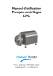
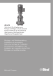
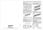
1
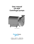
User manual Pomac CP – CP/ZA - ZA pumps User manual Pomac CP – CP/ZA - ZA pumps This manual has been compiled with the utmost care. However, POMAC assumes no liability for possible deficiencies of the information in this manual. It is the responsibility of the buyer/user of this pump to ensure this information is complete and up-to-date. All technical information mentioned in this user manual remains property of Pomac bv and may only be used for the installation, operation and maintenance of this pump. The information may not be copied, duplicated or passed on to third parties without our written permission. Copyright 2010 Pomac bv Release date: November 2012 Doc. ID. : CE/CP (1211) EN-3.1 CE/CP (1211) EN-3.1 1 User manual Pomac CP – CP/ZA - ZA pumps DECLARATION OF INCORPORATION (according to Annex II 1 B of the Machinery Directive (2006/42/EC – 1st Edition – December 2009) Pomac bv Feithspark 13 9356 BX Tolbert The Netherlands hereby declares completely under own responsibility that the pumps mentioned below: Model: Types: Execution: Materials: Centrifugal pump CP, CP/ZA, ZA KAM, KAV, KAV, IGH 1.4404 (AISI 316L) to which this declaration refers to, are in conformity with the following standards: Standards: EN-ISO 12100 parts 1 & 2 NEN-EN 60204 part 1 EN 809 The pump must not be put into service until the final machinery into which it is to be incorporated has been declared in conformity with the provisions of this Directive (2006/42/EC), where appropriate. Issued at Tolbert, 29th of December 2009 H. Poelstra Managing Director 2 CE/CP (1211) EN-3.1 User manual Pomac PLP Lobe pump Table of contents 1. Introduction ....................................................................................................................................... 5 1.1. General information................................................................................................................... 5 1.2. Warranty .................................................................................................................................... 5 1.3. Transport and receipt ................................................................................................................ 5 1.4. Pump identification .................................................................................................................... 6 1.5. Type code ................................................................................................................................. 7 1.6. Ordering spare parts ................................................................................................................. 8 1.7. Manufacturer ............................................................................................................................. 8 2. Safety ............................................................................................................................................... 9 2.1. General information................................................................................................................... 9 2.2. Instructions ................................................................................................................................ 9 2.3. Staff ........................................................................................................................................... 9 2.4. Precautions ............................................................................................................................. 10 2.5. Changed application ............................................................................................................... 10 3. Description ..................................................................................................................................... 11 3.1. CP centrifugal pump................................................................................................................ 11 3.1.1. Pump description ............................................................................................................. 11 3.1.2. Certification ...................................................................................................................... 11 3.1.3. Application area ............................................................................................................... 11 3.1.4. Pump impeller design ...................................................................................................... 11 3.1.5. Type description ............................................................................................................... 11 3.2. CP/ZA self-priming centrifugal pump ...................................................................................... 11 3.2.1. Pump description ............................................................................................................. 11 3.2.2. Application area ............................................................................................................... 11 3.2.3. Certification ...................................................................................................................... 12 3.3. ZA self-priming water ring pump ............................................................................................. 12 3.3.1. Pump description ............................................................................................................. 12 3.3.2. Application area ............................................................................................................... 12 3.4. Connections ............................................................................................................................ 12 3.5. Materials .................................................................................................................................. 12 3.6. Construction variants .............................................................................................................. 12 3.7. Shaft seals .............................................................................................................................. 13 3.7.1. Materials .......................................................................................................................... 13 3.7.2. Type indication code ........................................................................................................ 13 3.7.3. Explanation double action mechanical seals ................................................................... 14 3.8. Drive ........................................................................................................................................ 14 4. Installation ...................................................................................................................................... 15 4.1. General.................................................................................................................................... 15 4.2. Assembling Type IG ................................................................................................................ 15 4.3. Aligning the coupling IG/IGF design ....................................................................................... 16 4.4. Connecting the electric motor ................................................................................................. 16 5. Putting into operation ..................................................................................................................... 17 5.1. Precautions ............................................................................................................................. 17 5.1.1. General ............................................................................................................................ 17 5.1.2. Quench ............................................................................................................................ 17 5.1.3. Flush ................................................................................................................................ 17 5.2. Checking the rotation direction ............................................................................................... 17 5.3. Putting into operation .............................................................................................................. 17 5.4. In operation ............................................................................................................................. 18 5.4.1. Noise ................................................................................................................................ 18 5.4.2. Daily maintenance ........................................................................................................... 18 5.4.3. Cleaning procedure and agents ....................................................................................... 18 5.4.4. Periodic maintenance ...................................................................................................... 18 5.5. Malfunction .............................................................................................................................. 19 6. Overhaul and repair ........................................................................................................................ 20 6.1. Removing the pump ................................................................................................................ 20 6.2. Dismantling and assembling the pump ................................................................................... 20 6.2.1. Dismantling the pump ...................................................................................................... 20 CE/CP (1211) EN-3.1 3 User manual Pomac CP – CP/ZA - ZA pumps 6.2.2. Assembling the pump ...................................................................................................... 20 6.2.3. Adjusting the extension shaft ........................................................................................... 21 6.3. Dismantling and fitting the shaft seal ...................................................................................... 21 6.3.1. Instructions ....................................................................................................................... 21 6.3.2. Dismantling an interior mechanical seal (S1 - B1)........................................................... 22 6.3.3. Fitting an interior mechanical seal (S1 - B1) .................................................................... 22 6.3.4. Dismantling an exterior mechanical seal (S2) ................................................................. 22 6.3.5. Fitting an exterior mechanical seal (S2) .......................................................................... 22 6.3.6. Dismantling a shaft seal with quench (Q1-Q2) ................................................................ 23 6.3.7. Fitting a shaft seal with quench (Q1-Q2) ......................................................................... 23 6.3.8. Dismantling a shaft seal with flush (F1) ........................................................................... 23 6.3.9. Fitting a shaft seal with flush (F1) .................................................................................... 23 6.4. Dismantling and assembling bearings .................................................................................... 24 6.4.1. Dismantling bearing of IG construction ............................................................................ 24 6.4.2. Assembling bearing of IG construction ............................................................................ 24 6.5. Application IEC standard motors with extension shaft ............................................................ 24 7. Dimensions ..................................................................................................................................... 25 7.1. Dimensions drawings .............................................................................................................. 25 7.2. Dimensions CP ....................................................................................................................... 27 7.3. CP-WW ................................................................................................................................... 27 7.4. Dimensions CP/ZA .................................................................................................................. 27 7.5. Dimensions ZA ........................................................................................................................ 27 7.6. Dimensions of electric motors ................................................................................................. 28 8. Sectional drawings and parts lists .................................................................................................. 29 8.1. KAM construction .................................................................................................................... 29 8.2. KAC construction .................................................................................................................... 30 8.3. KAC(M) construction ............................................................................................................... 31 8.4. KAV construction ..................................................................................................................... 32 8.5. CP parts .................................................................................................................................. 33 8.6. CP/ZA parts ............................................................................................................................. 34 8.7. ZA parts ................................................................................................................................... 35 8.8. Parts of constructions IG and IGF ........................................................................................... 36 8.8.1. Sectional drawing............................................................................................................. 36 8.8.2. Parts list ........................................................................................................................... 37 8.8.3. IGH construction .............................................................................................................. 37 8.9. Shaft seals .............................................................................................................................. 38 8.9.1. Version S1 ....................................................................................................................... 38 8.9.2. Version S2 ....................................................................................................................... 38 8.9.3. Version B1 ....................................................................................................................... 39 8.9.4. Version Q1 ....................................................................................................................... 39 8.9.5. Version Q2 ....................................................................................................................... 40 8.9.6. Version F1 ........................................................................................................................ 40 9. Performance curves ....................................................................................................................... 41 -1 9.1. CP and CP/ZA, 2900 min ...................................................................................................... 41 -1 9.2. CP and CP/ZA , 1450 min ..................................................................................................... 41 -1 9.3. ZA , 1450 min ........................................................................................................................ 42 -1 9.4. Whey curd pump, 1000/750 min ........................................................................................... 42 10. Trouble shooting ......................................................................................................................... 43 4 CE/CP (1211) EN-3.1 User manual Pomac PLP Lobe pump 1. Introduction 1.1. General information This manual provides important information regarding the correct way of installing, operating and servicing this pump. This manual also provides information necessary to prevent the installer/operator from injury or discomfort during installation and operation of this pump and to ensure the correct use and reliable performance of this pump. This manual represents the most recent information regarding the pump types mentioned in this manual at the time of going to print. However, POMAC reserves the right to modify the construction of the pump types mentioned, as well as the contents of this manual, without prior or afterward notification. Read this manual thoroughly before installing, operating or servicing this pump. Ensure that operators and maintenance staff are familiar with the symbols used. Follow the instructions in this manual step by step. 1.2. Warranty Warranty is strictly limited to the conditions specified by POMAC and will only be granted according to these conditions. Warranty will only come into force provided that: 1.3. the pump has been installed and put into operation strictly in accordance with the instructions given in this manual. maintenance and repairs have been carried out according to the instructions given in this manual. exclusively original POMAC parts or parts provided by POMAC have been used for replacing parts. the pump has not been used for applications other than those shown in the specifications according to which the pump was sold. no changes have been made to the construction of the pump itself by the buyer. the damage is not the result of work carried out by persons not qualified or appointed. the damage has not been caused through major force. Transport and receipt 1. Check to see if the pump has not been subject to damage during transportation. If this is the case, report it directly to the carrier and to POMAC; 2. If the pump is delivered on a pallet, leave it on the pallet for as long as possible. This facilitates internal transport. 3. If a suitable hoisting device is available, use this if the pump is fitted with lifting eyes. 4. With the exception of the motors fitted with a stainless steel shroud, the motors (pumps) from construction size 112 or 132 can be fitted with a screw-in lifting eye. Motor size 100-112 132 Lifting eye thread size M8 M10 160 M10 180 M12 CE/CP (1211) EN-3.1 200 M16 5 User manual Pomac CP – CP/ZA - ZA pumps 1.4. Pump identification On the type plate of the pump the serial number and the type code are indicated. The type code describes the arrangement of the pump. Always refer to the serial number and the type code in any correspondence and when ordering parts. These pump data are also stated on the first page of this manual. If the pump type plate is missing, please provide us with the following details so that we can establish the correct pump size: Pump cover Diameter A Diameter E Depth C Diameter suction Diameter discharge Connection: Flange or coupling Impeller Diameter D1 Diameter D2 Diameter D3 Diameter D4 Impeller width B Blade width H Impeller type Closed, half open or open (star) Motor There is a motor type plate on the motor itself. 6 CE/CP (1211) EN-3.1 User manual Pomac PLP Lobe pump 1.5. Type code The type code consists of the following items: x 1 x 2 x 3 - x 4 - x 5 - x 6 - x 7 - x 8 - x 9 Example: CP 15544 – KAM – 2 – 0750 – S1 – AG - XPS 1. Type CP / CPZA / ZA 2. Pump size 155 / 195 / 235 / 290 / 360 3. Connection sizes 22 / 33 / 44 / 66 / 88 / 108 / 1210 4. Construction KAM / KAC / KAC(M) / KAV 5. Electric motor poles 2/4/6 6. Power 0.55 7.5 18.5 37 = = = = 0055 0750 1850 3700 7. Mechanical seal S1 = mechanical seal, unbalanced, internal S2 = mechanical seal, unbalanced, external B1 = mechanical seal, balanced, internal Q1 = double mechanical seal with Quench, unbalanced Q2 = double mechanical seal with Quench, 1-side balanced F1 = double mechanical seal, Back to Back, with Flush 8. Connections A = DIN 11851 B = SMS 1145 C = Tri Clamp D = DIN 11864-1 E = Flanges DIN 2633 F = special connection G = inch H = metric 9. Options V = heating jacket I = drain T = turbine X = ATEX P = PTC probe in electric motor S = extra surface roughness treatment internal parts W = internal parts hardened CE/CP (1211) EN-3.1 7 User manual Pomac CP – CP/ZA - ZA pumps 1.6. Ordering spare parts An order form for ordering spare part is included in the documents accompanying this pump. You should state the following details on this form: your address data the serial number and the type number (these are stated on the type plate of the pump and on the first page of this manual). the item numbers and quantities of the desired parts. See chapter 8 for the sectional drawings of the pump, with the corresponding parts lists with item numbers. 1.7. Manufacturer CP, CP/ZA and ZA pumps are manufactured by Pomac bv Feithspark 13 9356 BX Tolbert The Netherlands Tel +31(0) 594 5128 77 Fax +31(0) 594 5170 02 [email protected] www.pomacpumps.com 8 CE/CP (1211) EN-3.1 User manual Pomac PLP Lobe pump 2. Safety 2.1. General information This manual provides information necessary to prevent the installer/operator from injury or discomfort during installation and operation of this pump and to ensure the correct use and reliable performance of this pump. Read this manual thoroughly before installing, operating or servicing this pump. Ensure that operators and maintenance staff are familiar with the contents of this manual and with the instructions given. Ensure that operators and maintenance staff are familiar with the symbols used. Follow the instructions in this manual step by step. Store this manual in a place that is known and accessible to any user. 2.2. Instructions This manual contains instructions with regard to the safety of the user, the continued good functioning of the pump and hints to facilitate certain actions or procedures. These instructions are indicated with the following symbols: Warning! May cause injury to the user! Act strictly in accordance with the instructions given! ! Caution! May cause severe damage to the pump or bad functioning! Closely follow the instructions given! Note: Hint or instruction that can facilitate certain actions. Issues which require extra attention are printed in bold. 2.3. Staff All personnel, in charge of the installation, operation or maintenance and overhaul of the pump, should have received the necessary training. CE/CP (1211) EN-3.1 9 User manual Pomac CP – CP/ZA - ZA pumps 2.4. Precautions When performing maintenance work to the pump ensure that the drive of the pump is shut down and can not be switched on unintentionally! All work on and with the pump must always be in accordance with all the prevailing standards regarding occupational health and safety as well as machine safety! Always wear protective gloves and safety goggles if the pump conveys harmful liquids that may cause injuries! See to is that the pump is depressurized, when it has to be disassembled for overhaul! Allow the pump to cool down first when it is used for conveying hot liquids! 2.5. 10 Changed application Contact POMAC in case the pump is going to be used for other applications or in different circumstances than those specified during the initial pump selection. CE/CP (1211) EN-3.1 User manual Pomac PLP Lobe pump 3. Description 3.1. CP centrifugal pump 3.1.1. Pump description Stainless steel sanitary centrifugal pump that is used for pumping liquids up to 500 cP. For this process a liquid flow (with a pre-pressure or an underpressure) is constantly present on the suction side. 3.1.2. Certification Pump type CP is certified in accordance with the EHEDG directives. Pump type CP is ATEX certified. 3.1.3. Application area 3 The application area goes from a capacity of 300 m /h to a manometric head of 13 bars. 3.1.4. Pump impeller design Depending on the product to be pumped, the pumps can be supplied with: closed impeller. half open impeller. open impeller (suitable for pumping liquids with solid constituents). 3.1.5. Type description Depending on the area of application the following types are available: CP Stainless steel sanitary centrifugal pump designed with tangential outlet and suitable for system pressures up to 16 bars. Stainless steel sanitary centrifugal pump designed with tangential outlet and suitable for system pressures up to 50 bars. CP-H CP-IL Stainless steel sanitary centrifugal pump designed with 'InLine' connections. This makes it possible to build this pump directly in the piping. Available in construction sizes 15533 / 15544 / 19544 / 19555 / 19566 / 23544 / 23555 / 23566 / 23588. CP-WW Stainless steel centrifugal pump for whey curds. Designed with tangential outlet. This pump was especially designed for pumping soft and vulnerable media, such as whey curds. This -1 pump is therefore designed with a drive that has a maximum speed of 1000 min . Available in construction sizes 29088WW/36088WW. CP-T 3.2. Stainless steel sanitary centrifugal pump, designed with radial outlet (the outlet opening of the pump is located directly above the central axis of the suction opening). CP/ZA self-priming centrifugal pump 3.2.1. Pump description This pump type is an extension of the pump type CP mentioned above. The CP/ZA pump distinguishes itself from this by the self-priming operation. This makes the pump highly suitable for pumping liquid/air mixtures. 3.2.2. Application area 3 The application area goes from a capacity of 200 m /h to a manometric head of 9 bars. CE/CP (1211) EN-3.1 11 User manual Pomac CP – CP/ZA - ZA pumps 3.2.3. Certification Pump type CP/ZA is ATEX certified. 3.3. ZA self-priming water ring pump 3.3.1. Pump description This self-priming pump works according to the water ring principle and is therefore able to pump liquid/air mixtures. 3.3.2. Application area 3 The application area goes from a capacity of 60 m /h to a manometric head of 5 bars. 3.4. Connections All pump types are available with the following connections: Screw coupling according to DIN 11851 SMS 1145 Tri-clamp DIN 11864-1 DIN 11864-2 Flanges DIN 2633 BSP NPT Connections according to client specification 3.5. Materials All parts that come into contact with the liquid are designed in stainless steel 304 or 316L (Werkstoffnr. 1.4301 and 1.4404 respectively). All pumps are suitable for being C.I.P. cleaned. 3.6. Construction variants All pumps are available in the following, fully exchangeable designs: KAM Pump and motor close coupled and placed on adjustable stainless steel feet. The motor is provided with a stainless steel shroud. KAC Pump and motor close coupled and placed on a steel support. KAV Pump and motor close coupled and placed on the motor feet. 12 CE/CP (1211) EN-3.1 User manual Pomac PLP Lobe pump IG Pump fitted to a bearing bracket. IGF Pump fitted to a bearing bracket and connected to drive motor by means of flexible coupling and placed on a base plate. IL Pump with InLine connections. 3.7. Shaft seals 3.7.1. Materials The mechanical seals are standard according to EN 12756 (DIN 24960), with the exception of the build-in length. The mechanical seals are available in the following materials: Carbon on silicon carbide Carbon on CrMo-steel Carbon on Ceramic Hard metal on hard metal Silicon carbide on silicon carbide Tungsten carbide on tungsten carbide Carbon on hard metal The O-rings are available in: FPM (Viton) NBR EPDM PTFE Pomac pumps are supplied as standard with an interior unbalanced mechanical seal (carbon on silicon carbide with EPDM O-rings). 3.7.2. Type indication code Code S1 S2 B1 Q1 Q2 F1 Description interior single mechanical seal - unbalanced exterior single mechanical seal - unbalanced interior single mechanical seal - balanced double mechanical seal with Quench - unbalanced double mechanical seal with Quench - 1 side balanced double mechanical seal with Flush - unbalanced CE/CP (1211) EN-3.1 13 User manual Pomac CP – CP/ZA - ZA pumps 3.7.3. Explanation double action mechanical seals Quench This is applied where a constant pressure-free flush is required because of the product. This is applied when a considerable underpressure prevails on the suction side, or when a constant flushing is required in order to prevent fouling of the shaft seal. The pressure of the flushing fluid must always be higher than the discharge pressure of the pump. Flush 3.8. 14 Drive The designs KAM, KAC and IL are fitted with B5 flange motors acc. to IEC, provided with a balanced stainless steel extension shaft. From 11 kW on fitted with B3/B5 foot/flange motor. The design KAV is fitted with B3/B5 foot/flange motor acc. to IEC provided with a balanced stainless steel extension shaft. The electric motors are available in all possible voltages, insulation categories, protection categories and in low-noise and in ATEX design. The designs IG and IGF are available with air-driven, hydro, combustion and electric motors. CE/CP (1211) EN-3.1 User manual Pomac PLP Lobe pump 4. Installation 4.1. General The foundation must be smooth and level. For the KAM design set the adjustable legs using the leg adjustment bolts (510), in such a way that the pump is stable on all 4 legs! Secure the leg adjustment bolts with the lock nuts (511). Verify that the system pressure does not exceed the permitted operating pressure. Verify that the pipes do not show any leakage. The pipes must be installed and connected stress-free. Place a filter in front of the pump when installing a self-priming pump (ZA). The gap between the impeller and the pump casing is only 0.3 mm here, and misalignments can cause the pump to drag or seize. If backflow of the liquid flow is undesired, or there is a chance of undesired liquid mixing, apply a non-return valve. ! 4.2. For pump type CP/ZA a non-return valve must never be placed in the discharge pipe: it must be possible to discharge the air pumped with the suction through the discharge opening without resistance! Assembling Type IG Type IG can be assembled with all drives. Proceed as follows: 1. Fit one coupling half to the pump shaft and one half to the drive shaft. 2. Place the pump on the foundation and fix it. 3. Place the drive on the foundation. Keep a gap of 3 mm between both coupling halves. 4. Level the drive to the correct height in relation to the pump using the copper shims under the motor legs. Fix the motor. 5. Align the coupling according to the following instructions. CE/CP (1211) EN-3.1 15 User manual Pomac CP – CP/ZA - ZA pumps 4.3. Aligning the coupling IG/IGF design After assembly and installation of the pump unit, the alignment of the coupling must be checked. This can be done using special aligning equipment, or by following the method described below: 1. Place a ruler over the coupling. The ruler must touch the coupling halves over the entire width, see figure 1. Figure 1 2. Repeat this procedure at the 3 different places around the coupling. 3. The adjustment can also be carried out using a pair of callipers on 2 points of the side surfaces of the coupling located opposite each other, see figure 2. Figure 2 4.4. Connecting the electric motor An electric motor may only be connected by a qualified electrician! 16 CE/CP (1211) EN-3.1 User manual Pomac PLP Lobe pump 5. Putting into operation 5.1. Precautions 5.1.1. General Check that the shaft can turn freely. To do this, rotate the pump shaft a few times manually. Check that the fuses have been fitted. Type IG(F)(H) is designed as standard with grease lubricated ball bearings that are provided with grease for their entire life (2RS1). If type IG(F)(H) is designed with oil lubricated bearings, the bearing housing should be filled with oil first. 5.1.2. Quench If provided with quench (shaft seals Q1 and Q2): 1. Connect the quench lines to the quench space. Capacity approx. 3 l/min. The SUPPLY line must be connected to the LOWER port! 2. Open the inlet and outlet of these lines. 3. Set the required pressure. The maximum pressure is 0.2 bar. 5.1.3. Flush If provided with flush (shaft sealing F1): 1. Connect the flush lines to the flush space. The flushing must have a capacity of approx. 3 ltr/min. The SUPPLY line must be connected to the LOWER port! 2. Open the inlet and outlet of these lines. 3. Set the required pressure. This must be 2 bars higher than the maximum occurring system pressure! 5.2. Checking the rotation direction 1. Fill the pump with the medium to be pumped. 2. Check that the quench or flush system is set to the correct pressure. 3. Switch the pump on briefly. Take care with any unprotected rotating parts! 4. Check that the rotation direction of the motor corresponds with the rotation direction of the pump (which is indicated by an arrow on the lantern piece). If the rotation direction is not correct, swap the connection wires L1 and L2. This must be done by a qualified electrician! 5. Fit the guard. 5.3. Putting into operation 1. Check that the quench or flush system is set to the correct pressure. 2. Fully open the shut-off-valve in the suction pipe. 3. Only for CP: Close the delivery valve. 4. Switch the pump on and allow it to come up to pressure. 5. Only for CP: Subsequently open the delivery valve. 6. Set the pump to its required operating point. CE/CP (1211) EN-3.1 17 User manual Pomac CP – CP/ZA - ZA pumps 5.4. In operation 5.4.1. Noise The noise data stated in this manual refer to normal usage, with an electric motor. Under these conditions the noise level, measured at a distance of 1 meter and at a height of 1,6 meter, is below 85 dB(A). If after the passage of time the pump produces excessive noise, this can be an indication that there is a fault in the pump or elsewhere in the system (e.g. worn out bearings, cavitation). 5.4.2. Daily maintenance ! Regularly check the pressure of quench or flush supply if the shaft seal is equipped with it. ! Check that the high flush pressure does not provoke any undesired leakage to the liquid to be pumped. The valve in the suction pipe must always be completely open Regularly check that the inlet pressure is not too low to avoid the occurrence of cavitation in the pump Regularly check the delivery pressure Regularly check the shaft seals for leakage. The pump may never run without liquid 5.4.3. Cleaning procedure and agents The pumps are suitable for being CIP cleaned. Use the cleaning agents recommended for the products. 5.4.4. Periodic maintenance CP, CPZA and the ZA pumps basically are maintenance free. Only the following items require periodic attention: ! Periodically check that the quench or flush system is still set at the correct pressure and capacity! The electric motor bearings are greased for their entire life and do not require any maintenance or subsequent lubrication. This also applies to the designs IG, IGF and IGH, if designed with grease lubricated bearings. Regularly check the oil level for designs IG, IGF and IGH, designed with oil bath lubricated bearings. This oil must also be changed annually or after every 5000 operating hours. Check that the spent oil is disposed of in the correct manner (environment)! A mechanical seal may not show any visible leakage. If this is the case, replace the shaft seal. If a mechanical seal does not show any visible leakage disassembly is not recommended! 18 CE/CP (1211) EN-3.1 User manual Pomac PLP Lobe pump 5.5. Malfunction If there is a malfunction in the pump, try to find the cause using the troubleshooting list at the back of this manual or consult your installer! Always switch off the current first if you intend to investigate the malfunction yourself. Remove the fuse or lock the operating switch with a pad lock! The pump can still be hot or under pressure. Allow the pump to cool down first and if possible release the pressure from the pump. Always wear the correct personal protection devices (goggles, gloves, etc.)! CE/CP (1211) EN-3.1 19 User manual Pomac CP – CP/ZA - ZA pumps 6. Overhaul and repair 6.1. Removing the pump First ensure the electric current has been switched off. Remove the fuses or switch the operating switch to OFF and lock it with a pad lock! If the pumped liquid is HOT, first allow the pump to cool down! 1. Disconnect the electrical connections to the electric motor. 2. For designs Q1, Q2 and F1 disconnect the flushing lines. 3. Loosen the connections of the pipes and remove the pump from the piping. 6.2. Dismantling and assembling the pump The item numbers shown (...) refer to the illustrations and the parts lists in chapter 7 6.2.1. Dismantling the pump 1. Loosen the pump cover nuts (522) and remove the pump cover (1). Inspect the pump cover O-ring (505) for damage. 2. Remove the pump shaft nut (3) and remove the impeller (2) and the O-ring (563). 3. Remove the sunk key (504). 4. If necessary dismantle the shaft seal. 5. If necessary dismantle the stub shaft. 6.2.2. Assembling the pump 1. If it has been dismantled: fit the extension shaft (49). This has to be adjusted before the pump can be further assembled, see next paragraph. 2. If it has been dismantled: fit the shaft seal (519). 3. For an interior seal check that the spring of the seal is positioned firmly against the collar of the shaft sleeve! 4. Put the sunk key (504) into the key way in the shaft and push the impeller onto the shaft. 5. Place the O-ring (563) and fit the pump shaft nut (3). ! Use a feeler gauge to check that the gap between the impeller and the rear plate is correct, for values see the table in the next paragraph. If this is not the case, readjust the extension shaft! 6. Place the pump cover O-ring (505). Fit the pump cover (1) and tighten the pump cover nuts (522). 20 CE/CP (1211) EN-3.1 User manual Pomac PLP Lobe pump 6.2.3. Adjusting the extension shaft For versions KAM, KAC and KAV before the final assembly the extension shaft first must be adjusted on the motor shaft to set the proper gap between the impeller and the back plate later. 1. If dismantled, fit the lantern piece (15) and the back plate (6). 2. If provided with shaft sealing F1, fit shaft sleeve (23) on the extension shaft. Fit the impeller (2) and the pump shaft nut (3) to the extension shaft and fit the extension shaft to the motor shaft. 3. Place a feeler gauge of the correct thickness X between the impeller and the back plate (ZA: pump casing). Gently tighten the bolts of the extension shaft. Do not tighten the Allen screw for disassembly of the extension shaft too much. Pump type CP - CP/ZA Ø impeller ≤ 200 mm CP - CP/ZA Ø impeller >200 mm ZA X 1 mm 1,5 mm 0,3 mm 4. Dismantle the impeller and the back plate and assemble the pump according to the relevant instructions. 5. Check the extension shaft for oscillation. This must not be more than 0.05 mm. 6.3. Dismantling and fitting the shaft seal 6.3.1. Instructions The fitting/dismantling instructions can differ between manufacturers. You will find below the fitting/dismantling instructions for the most commonly applied mechanical seals in Pomac pumps. ! In other cases, always follow the instructions that are provided by the supplier of the seal in question! CE/CP (1211) EN-3.1 21 User manual Pomac CP – CP/ZA - ZA pumps 6.3.2. Dismantling an interior mechanical seal (S1 - B1) 1. Dismantle the pump cover and the impeller. 2. Remove the rotating ring of the mechanical seal (519) from the extension shaft 3. Dismantle the back plate (6). 4. Push the static ring of the mechanical seal (519) out of the seal seat (20). 6.3.3. Fitting an interior mechanical seal (S1 - B1) 1. If it has been disassembled: Place the O-ring (508) and refit the seal seat (20) to the back plate (6) with bolts (507) and washers (506). 2. Apply some food grade grease to the seal seat (20) and press the static ring of the mechanical seal (519) into the seal seat. 3. Fit the back plate (6) to the lantern piece (15) with bolts (521) and washers (520). 4. Apply some food grade grease to the extension shaft and push the rotating parts of the mechanical seal (519) onto the shaft. 5. For shaft seal B1: line up the rear side of the mechanical seal with the shaft collar and fix the lock screws. 6. Fit the impeller and the pump cover. 6.3.4. Dismantling an exterior mechanical seal (S2) 1. Dismantle the pump cover, the impeller and the back plate (6). 2. Disassemble the back plate (6). 3. Push the static ring of the mechanical seal (532) out of the seal seat (20). 4. Remove the rotating ring of the mechanical seal (532) from the shaft. 6.3.5. Fitting an exterior mechanical seal (S2) 1. If it has been disassembled: Fit the adjusting ring (549) and adjust it according to figure 3 and the values from the table below. Figure 3 Applied for [kW] ! D [mm] X ± 0.5 [mm] Up to 4 25 29 5,5 to 7,5 30 29 11 to 22 35 33,5 30 to 37 40 38 45 to 55 45 39,5 In case of different seal constructions follow the fitting instructions supplied by the manufacturer! 2. Apply some food grade grease to the shaft and push the rotating part of the mechanical seal (532) onto the shaft, the seal face facing the impeller. 22 CE/CP (1211) EN-3.1 User manual Pomac PLP Lobe pump 3. If it has been disassembled: Place the O-ring (508) and refit the seal seat (20) to the back plate (6). 4. Apply some food grade grease to the seal seat (20) and press the static ring of the mechanical seal (532) into the seal seat. 5. Fit the back plate (6) to the lantern piece (15) with bolts (521) and washers (520). 6. Fit the impeller and the pump cover. 6.3.6. Dismantling a shaft seal with quench (Q1-Q2) 1. Dismantle the impeller and the pump cover. 2. Push the rotating parts of the mechanical seal (519) from the shaft. In case of a balanced seal (Q2) loosen the lock screws of the rotating part of the seal. 3. Disassemble the back plate (6) and the seal housing (20) and remove both static rings of the mechanical seals (519 and 532 / 567) from the seal seats of the seal housing. 4. Remove the rotating part of the other mechanical seal (532 / 567) from the shaft. 6.3.7. Fitting a shaft seal with quench (Q1-Q2) 1. If it has been disassembled: Fit the adjusting ring (549) and adjust it according to figure 3 and the corresponding table. 2. Fit the rotating part of the mechanical seal with the left-wound spring (532) onto the shaft, the seal face facing the impeller. 3. If it has been disassembled: Place the O-ring (508) and refit the seal housing (20) to the back plate (6). 4. Apply some food grade grease to the seal seats and push both static rings of the mechanical seals (532 and 519) in the seal seats of the seal housing (20). The static ring belonging to the exterior seal (532) is fitted at motor side. 5. Fit the back plate (6) with the seal housing (20). 6. Q1: Fit the rotating part of the other mechanical seal (519) onto the shaft. 7. Q2: Fit the rotating part of the other mechanical seal (567) onto the shaft. Line up the rear side of the mechanical seal with the shaft collar and tighten the lock screws. 8. Fit the impeller and the pump cover. 6.3.8. Dismantling a shaft seal with flush (F1) 1. Dismantle the pump cover and the impeller. 2. Remove the flush supply lines. 3. Remove the back plate (6) from the lantern piece (15). 4. Remove the entire flush-configuration (20) including the shaft sleeve (23). Remove the Oring (565). 5. Remove the seal seat (20) from the back plate and remove the O-rings (508) and the fixing ring (253). 6. Push the static rings of both mechanical seals (519 / 532) out of their respective seats. 7. Pull the rotating rings of both mechanical seals (519 / 532) from the shaft sleeve. Remove the shaft lock ring (517). 6.3.9. Fitting a shaft seal with flush (F1) 1. Apply some food grade grease into the seal seats and push both static rings of the mechanical seals (519 / 532) in their respective seats. 2. Apply some food grade grease to the shaft sleeve (23) and introduce the shaft sleeve from outside in through the short part of the seal seat (20). 3. Place the fixing ring (253) over the static seal ring in the short part of the seal seat (20). 4. Fit the rotating ring of the mechanical seal (532) onto the shaft sleeve, the seal face facing the static seal ring. 5. Fit a support ring (251) onto the shaft sleeve, bearing against the seal spring. 6. Fit the shaft locking ring (517) onto the shaft sleeve. 7. Fit the other support ring (251) onto the shaft sleeve. 8. Fit the rotating ring of the other mechanical seal (519) onto the shaft sleeve, the seal face facing outward and the spring bearing to the support ring. This set-up is called a Back to Back assembly. 9. Fit both O-rings (508). Assemble both halves of the seal seat and fit the assembly to the back plate (6). CE/CP (1211) EN-3.1 23 User manual Pomac CP – CP/ZA - ZA pumps 10. Fit the O-ring (565) onto the shaft and push it against the collar. 11. Push the entire subassembly onto the shaft and fit the back plate (6) to the lantern piece (15). 12. Ensure the shaft sleeve does not slip out of the seal seat! 13. Fit the impeller and the pump cover. 6.4. Dismantling and assembling bearings First dismantle the pump unit to the extent that the following parts can be reached and can be dismantled. 6.4.1. Dismantling bearing of IG construction 1. Remove the pump. 2. Remove the electric motor and the coupling. 3. Drain the bearing bracket (38) through the lower plug (560), if the bearing is provided with oil-bath lubricated bearings. 4. Remove the bearing cover (34) and the intermediate piece (28). 5. Remove the outer circlip (517) from the bearing at drive side and push the shaft with the other bearing out of the bearing bracket. 6. Remove the other outer circlip (517) and remove the bearing from the shaft. 7. Remove the bearing from the bearing bracket. 6.4.2. Assembling bearing of IG construction ! First check both oil catchers (537) in the intermediate piece (28) and the bearing cover (34). Replace them if they are damaged! Lubricate the inner and outer ring of the bearing, shaft and bearing seats in order to prevent seizing up. 1. Press the bearing (533) into the bearing bracket (38) at pump side. 2. Fit the intermediate piece (28). 3. Insert the shaft (29) with the screw thread forward from the motor side through the bearing in the bearing bracket (38) 4. Loosen the intermediate piece (28) and fix the bearing to the shaft with outer circlip (517). 5. Refit the intermediate piece (28). 6. Fit the second bearing and fix it to the shaft with outer circlip (517). 7. Fit the bearing cover (34). 8. Fit the electric motor and the coupling. For aligning the coupling and filling the bearing bracket with oil (version IG_), see the respective paragraphs. 6.5. ! 24 Application IEC standard motors with extension shaft When replacing a standard IEC standard electric motor the new motor must always be designed with an axially fixed shaft! CE/CP (1211) EN-3.1 User manual Pomac PLP Lobe pump 7. Dimensions 7.1. Dimensions drawings CE/CP (1211) EN-3.1 25 User manual Pomac CP – CP/ZA - ZA pumps 26 CE/CP (1211) EN-3.1 User manual Pomac PLP Lobe pump 7.2. Dimensions CP Construction size 15533 15544 19544 19555 19566 23544 23555 23566 23588 29044 29055 29066 29088 290108 36044 36055 36066 36088 360108 3601210 d1 d2 d3 1,5" 2" 2" 2,5" 3" 2" 2,5" 3" 4" 2" 2,5" 3" 4" 5" 2" 2,5" 3" 4" 5" 6" 1,5" 2" 2" 2,5" 3" 2" 2,5" 3" 4" 2" 2,5" 3" 4" 4" 2" 2,5" 3" 4" 4" 5" 200 200 239 239 239 280 280 280 280 339 339 339 339 339 410 410 410 410 410 410 NW 50 50 65 65 50 65 80 100 b 63 63 80 80 70 102 103 90 86 132 123 113 115 115 159 156 147 144 144 120 b1 34 34 41 38 34 41 45 49 e e2 120 140 160 160 160 180 180 180 200 200 200 200 215 215 230 230 250 245 245 320 180 190 190 200 220 220 225 240 f 69 69 69 74 81 69 74 81 92 69 74 81 92 92 85 87 94 105 113 125 f2 f3 98 98 98 98 98 98 98 98 49 49 52 55 49 52 55 61 L1 115 115 115 120 129 115 120 129 147 119 124 133 147 159 138 143 152 167 179 191 7.3. CP-WW For the dimensions of the CP-WW (whey curds pump) the dimensions of construction size 29088/36088 can be taken. 7.4. Dimensions CP/ZA Construction size 15533 15544 19544 19555 19566 23544 23555 23566 23588 29044 29055 29066 29088 290108 36044 36055 36066 36088 360108 7.5. d1 1,5" 2" 2" 2,5" 3" 2" 2,5" 3" 4" 2" 2,5" 3" 4" 5" 2" 2,5" 3" 4" 5" d2 1,5" 2" 2" 2,5" 3" 2" 2,5" 3" 4" 2" 2,5" 3" 4" 4" 2" 2,5" 3" 4" 4" b 77 77 92 92 87 113 113 113 98 138 138 133 118 118 181 176 176 161 161 e 224 224 254 258 258 334 338 339 353 334 338 339 353 353 479 483 484 498 498 f 153 153 153 176 191 153 176 191 233 153 176 191 223 223 153 176 191 233 223 y 115 115 145 145 145 220 220 220 195 220 220 220 195 195 330 330 330 330 330 L7 132 132 139 136 132 139 143 147 L1 189 189 189 237 257 204 237 257 314 204 237 257 304 304 204 237 257 257 294 Dimensions ZA Construction size 930-515 40066 44086 48066 d1 2” 3" 4" 3” d2 2 ½” 3" 4" 3” e1 194 198 211 230 f1 205 191 207 - CE/CP (1211) EN-3.1 L6 242 223 239 - 27 User manual Pomac CP – CP/ZA - ZA pumps 7.6. Dimensions of electric motors Motor size Power [kW] IEC 3000 1500 1000 750 80M 0,75 0,55 0,37 0,18 116 151 180 80 255 156 92 106 230 279 307 120 150 29 43 110 125 185 100 10 427 368 80M 1,1 0,75 0,55 0,25 116 151 180 80 255 156 92 106 230 279 307 120 150 29 43 110 125 185 100 10 427 368 90S 1,5 1,1 0,75 0,37 116 151 180 90 255 174 92 106 230 279 307 120 150 29 43 110 140 191 100 10 427 416 90L 2,2 1,5 1,1 0,55 116 151 180 90 255 174 92 106 230 279 307 120 150 29 43 110 140 191 125 10 427 416 100L 2,2 a a1 c c1 c4 D D1 g g1 h H H1 i j k k1 l u V W x L2 L3 0,75 152 164 194 100 305 195 102 116 300 317 347 140 180 39 53 135 160 208 140 12 497 458 100L 3 3 1,5 1,1 152 164 194 100 305 195 102 116 300 317 347 140 180 39 53 135 160 208 140 12 497 458 112M 4 4 2,2 1,5 152 164 194 112 305 220 102 116 300 317 347 140 180 39 53 135 190 215 140 12 497 479 132S 5,5 5,5 3 2,2 186 187 219 132 355 259 122 136 360 365 394 160 230 59 73 165 216 254 140 12 567 539 132S 7,5 186 187 219 132 355 259 122 136 360 365 394 160 230 59 73 165 216 254 140 12 567 539 3 186 187 219 132 355 259 122 136 360 365 394 160 230 59 73 165 216 254 178 12 567 539 132M 7,5 5,5 11 7,5 160M 11 160M 15 160L 18,5 15 180M 22 18,5 180L 200L 30 200L 37 225M 45 28 4 320 390 183 160 310 196 447 443 254 308 210 14 730 679 5,5 320 390 183 160 310 196 447 443 254 308 210 14 730 679 11 7,5 320 390 183 160 310 196 447 443 254 308 254 14 730 679 320 390 203 180 364 196 447 520 279 321 241 14 860 759 22 15 11 320 390 203 180 364 196 447 520 279 321 241 14 860 759 30 18,5 15 370 445 223 200 402 198 520 570 318 343 305 18 865 820 370 445 223 200 402 198 520 570 318 343 305 18 865 820 416 490 248 225 445 213 521 615 356 357 311 18 900 856 22 CE/CP (1211) EN-3.1 User manual Pomac PLP Lobe pump 8. Sectional drawings and parts lists 8.1. KAM construction Item no. 1 2 3 6 13 15 20 41 49 109 504 505 506 507 508 509 510 511 516 519 520 521 522 526 527 528 551 563 802 803 862 863 Quantity 1 1 1 1 1 1 1 1 1 1 1 1 4 4 1 2 4 4 1 1 4 4 4 2 4 4 2 1 4 4 2 2 Description pump cover impeller shaft nut back plate motor shroud intermediate piece seal seat guard for intermediate piece extension shaft mounting flange for motor shroud key O-ring washer bolt O-ring bolt leg adjustment bolt counter nut B5 flange motor mechanical seal washer bolt pump cover nut bolt nut washer bolt O-ring set screw washer bolt washer CE/CP (1211) EN-3.1 29 User manual Pomac CP – CP/ZA - ZA pumps 8.2. KAC construction Item no. 1 2 3 6 15 20 25 41 49 504 505 506 507 508 509 516 519 520 521 522 526 527 528 551 563 802 803 862 863 30 Quantity 1 1 1 1 1 1 1 1 1 1 1 4 4 1 2 1 1 4 4 4 2 4 4 2 1 4 4 2 2 Description pump cover impeller shaft nut back plate intermediate piece seal seat console guard for intermediate piece extension shaft key O-ring washer bolt O-ring bolt B5 flange motor mechanical seal washer bolt pump cover nut bolt nut washer bolt O-ring set screw washer bolt washer CE/CP (1211) EN-3.1 User manual Pomac PLP Lobe pump 8.3. KAC(M) construction Item no. 1 2 3 6 13 15 20 25 41 49 504 505 506 507 508 509 516 519 520 521 522 526 527 528 551 563 802 803 862 863 Quantity 1 1 1 1 1 1 1 1 1 1 1 1 4 4 1 2 1 1 4 4 4 2 4 4 2 1 4 4 2 2 Description pump cover impeller shaft nut back plate motor shroud intermediate piece seal seat console guard for intermediate piece extension shaft key O-ring washer bolt O-ring bolt B5 flange motor mechanical seal washer bolt pump cover nut bolt nut washer bolt O-ring set screw washer bolt washer CE/CP (1211) EN-3.1 31 User manual Pomac CP – CP/ZA - ZA pumps 8.4. KAV construction Item no. 1 2 3 6 15 20 41 49 504 505 506 507 508 516 519 520 521 522 526 527 528 551 563 802 862 863 32 Quantity 1 1 1 1 1 1 1 1 1 1 4 4 1 1 1 4 4 4 4 4 8 2 1 4 2 2 Description pump cover impeller shaft nut back plate intermediate piece seal seat guard for intermediate piece extension shaft key O-ring washer bolt O-ring B3/B5 foot/flange motor mechanical seal washer bolt pump cover nut bolt nut washer bolt O-ring set screw bolt washer CE/CP (1211) EN-3.1 User manual Pomac PLP Lobe pump 8.5. CP parts Item no. 1 2 3 6 20 504 505 506 507 508 519 522 563 802 Description Pump cover Impeller Shaft nut Back plate Seal seat Key O-ring Washer Bolt O-ring Mechanical seal Pump cover nut O-ring Set screw CE/CP (1211) EN-3.1 33 User manual Pomac CP – CP/ZA - ZA pumps 8.6. CP/ZA parts Item no. 1 2 3 6 20 93 504 505 506 507 508 519 522 563 802 34 Description Pump cover with casing Impeller Shaft nut Back plate Seal seat Suction connection Key O-ring Washer Bolt O-ring Mechanical seal Pump cover nut O-ring Set screw CE/CP (1211) EN-3.1 User manual Pomac PLP Lobe pump 8.7. ZA parts Item no. 1 2 3 6 504 505 519 522 549 563 802 Description Pump cover with casing Impeller Shaft nut Back plate Key O-ring Mechanical seal Pump cover nut Splash ring O-ring Set screw CE/CP (1211) EN-3.1 35 User manual Pomac CP – CP/ZA - ZA pumps 8.8. Parts of constructions IG and IGF 8.8.1. Sectional drawing 36 CE/CP (1211) EN-3.1 User manual Pomac PLP Lobe pump 8.8.2. Parts list The bold printed item numbers belong to the IG construction. Item no. 28 29 30 34 38 39 40 43 47 48 504 516 517 524 - 526 528 533 535 536 537 541- 542 - 545 560 589 804 - 805 - 806 - 807 Description Intermediate piece Pump shaft Bearing bracket support (IGF) Bearing cover Bearing bracket Console Base plate Spacer foot electric motor B3 Coupling guard Coupling Key B3 foot motor IEC standard Circlip Bolt Washer Ball bearing Bolt Key Oil seal Bolt Plug + sealing ring Loose feet for B3 electric motor Washer 8.8.3. IGH construction IGH is an IG construction, driven by a flanged-on hydromotor. CE/CP (1211) EN-3.1 37 User manual Pomac CP – CP/ZA - ZA pumps 8.9. Shaft seals 8.9.1. Version S1 Interior mechanical seal, unbalanced. Item no. 6 20 508 519 Description back plate seal seat O-ring mechanical seal 8.9.2. Version S2 Exterior mechanical seal, unbalanced. Item no. 6 20 508 532 549 38 Description back plate seal seat O-ring mechanical seal with left-wound spring set ring CE/CP (1211) EN-3.1 User manual Pomac PLP Lobe pump 8.9.3. Version B1 Interior mechanical seal, balanced. Item no. 6 20 508 567 Description back plate seal seat O-ring mechanical seal 8.9.4. Version Q1 Interior unbalanced mechanical seal with unbalanced quench seal. Item no. 6 20 508 519 532 549 Description back plate seal seat O-ring mechanical seal mechanical seal with left-wound spring set ring CE/CP (1211) EN-3.1 39 User manual Pomac CP – CP/ZA - ZA pumps 8.9.5. Version Q2 Interior balanced mechanical seal with unbalanced quench seal. Item no. 6 20 508 532 549 567 Description back plate seal seat O-ring mechanical seal with left-wound spring set ring mechanical seal 8.9.6. Version F1 Double mechanical seal, back-to-back, unbalanced. Item no. 6 20 20 23 251 253 508 517 519 532 565 40 Description back plate seal seat seal seat back-to-back with liquid lock shaft sleeve support ring lock ring for static seal ring O-ring circlip mechanical seal (atmospheric side) mechanical seal with left-wound spring (pump side) O-ring CE/CP (1211) EN-3.1 User manual Pomac PLP Lobe pump 9. Performance curves 9.1. CP and CP/ZA, 2900 min 9.2. CP and CP/ZA , 1450 min -1 -1 CE/CP (1211) EN-3.1 41 User manual Pomac CP – CP/ZA - ZA pumps -1 9.3. ZA , 1450 min 9.4. Whey curd pump, 1000/750 min 42 -1 CE/CP (1211) EN-3.1 User manual Pomac PLP Lobe pump 10. Trouble shooting A malfunction in a pump system may have various causes. The malfunction is not always necessarily in the pump itself, but can also be caused by a malfunction in the piping system, or in another appendage in the system. If the operating conditions differ too greatly from the specifications by which the pump was purchased this can also cause malfunctioning. Therefore always check first: Has the pump been installed correctly? Are the operating conditions still according to the initial specifications? Are the other appendages in the pipe system functioning correctly? In general terms, the following malfunctions in a pump can be distinguished: 1. 2. 3. 4. 5. 6. 7. 8. 9. pump gives no or little liquid pump does not reach duty point pump gives irregular liquid flow pump leaks pump vibrates excessively pump makes too much noise motor overheats pump cuts out thermally pomp has seized The table on the next page gives a possible cause and solution for the malfunctions mentioned above: CE/CP (1211) EN-3.1 43 User manual Pomac CP – CP/ZA - ZA pumps Malfunction 1 2 3 4 Cause 5 6 7 8 Action 9 electrical connection defective Have qualified electrician check the electric connections wrong rotation direction Have qualified electrician reverse the sense of rotation of the electric motor pump is not completely filled Top up the pump entirely with liquid (only for CP) with liquid insufficient pre-pressure Increase the pre-pressure or place the pump on a lower position pump operating at the wrong Check the motor speed speed contaminations or objects in Clean the pump, if the pump necessary disassemble air in the piping Inspect the piping valve in suction pipe is not Entirely open the valve in completely open the suction pipe pump selected with too Install another pump small delivery head suction pipe or filter blocked Clean the suction pipe or the filter shaft seal defective Disassemble the pump and replace the shaft seal O-ring seal defective Disassemble the pump and replace the O-ring seal liquid temperature is too Decrease the liquid high temperature impeller is jammed Disassemble the pump and replace the impeller impeller is damaged Disassemble the pump and replace the impeller motor shaft is bent Replace the motor extension shaft is loose Disassemble the pump, inspect the extension shaft, reassemble it and readjust. bearings are damaged or Replace the motor. For worn IG(F): replace the bearings motor is overloaded Check the viscosity of the liquid. Switch off the motor and check if the pump does not drag. If so, disassemble the pump and repair it 44 CE/CP (1211) EN-3.1 User manual Pomac PLP Lobe pump Index 2RS1, 17 address data, 8 asafdichting, 17, 20 ATEX, 7, 11, 12, 14 axially fixed shaft, 24 base plate, 13 bearings assembling, 24 dismantling, 24 C.I.P., 12 callipers, 16 cavitation, 18 centrifugal pump, 11 Changed application, 10 Cleaning agents, 18 Cleaning procedure, 18 Connection sizes, 7 Connections, 7, 12, 20, 44 Construction, 7, 12, 27 contaminations, 44 coupling, 16 aligning, 6, 12, 15, 16 CP, 7, 11, 12, 21, 33, 41 CP/ZA, 11, 12, 21, 34, 41 CP-WW, 11, 27 Dimensions, 25 electric motor, 28 Dimensions drawings, 25 drain, 7 Drive, 14 EHEDG directives, 11 electric motor, 16, 18, 44 Electric motor poles, 7 EN 12756 (DIN 24960), 13 extension shaft, 14, 20, 21, 24, 44 flexible coupling, 13 flush, 17 Flush, 7, 13, 14, 17 gap, 15, 20, 21 General information, 5, 9 guard, 17 heating jacket, 7 IEC, 24 injury, 5, 9 InLine connections, 11, 13 Introduction, 5 lifting eyes, 5 lines, 17, 20 liquid/air mixtures, 11, 12 maintenance daily, 1, 5, 9, 10, 18 periodic, 18 major force, 5 malfunction, 19, 43 Manufacturer, 8 mechanical seal, 7, 13 non-return valve, 15 Note, 9 occupational health and safety, 10 order form, 8 Ordering spare parts, 8 original POMAC parts, 5 O-rings, 13 oscillation, 21 overhaul, 9, 10 Overhaul, 20 pad lock, 19, 20 parts lists, 8, 20, 29 Performance curves, 41 personal protection, 19 personnel, 9 training, 9 piping, 11, 20, 43, 44 Precautions, 10 pre-pressure, 11, 44 pump, 1, 5, 6, 8, 9, 10, 11, 12, 14, 15, 16, 17, 18, 19, 20, 24 assembling, 20 dismantling, 20 Pump identification, 6 qualified electrician, 16, 17, 44 quench, 17 Quench, 7, 13, 14, 17 radial outlet, 11 repair, 20, 44 rotation direction, 17, 44 ruler, 16 Safety, 9 sectional drawing, 8 Sectional drawings, 29 self-priming operation, 11 serial number, 6, 8 shaft seal dismantling, 21 fitting, 21 Shaft seals, 38 shut-off-valve, 17 speed, 44 Staff, 9 stainless steel shroud, 5, 12 standard electric motor, 24 standards, 10 tangential outlet, 11 Transport, 5 Transport and receipt, 5 Trouble shooting, 43 turbine, 7 type code, 6, 7 Type indication code, 13 type number, 8 CE/CP (1211) EN-3.1 45 User manual Pomac CP – CP/ZA - ZA pumps type plate, 6 underpressure, 11, 14 visible leakage, 18 Warranty, 5 46 water ring pump, 12 Whey curd pump, 42 whey curds, 11, 27 ZA, 7, 12, 21, 27, 35, 42 CE/CP (1211) EN-3.1