1
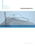
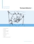
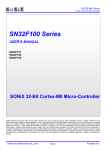
Anterior Lumbar
Bone Lever System
User Manual
Uncompromised Exposure.
ANTERIOR LUMBAR BONE LEVER SYSTEM USER MANUAL
Prior to use, inspect all parts for damage: DO NOT use if any part has been deformed, altered, or damaged in any way.
PATIENT POSITIONING AND TABLE MOUNT SET UP:
STEP 1
Position the patient supine for an anterior retroperitoneal
surgical exposure of the anterior lumbar disc space. A
slight Trendelenburg position may be used for lower lumbar
levels. Alternate to the supine positioning, the patient may
be placed in the DaVinci position (shown to left) to allow the
surgeon to view the spine from a straight vantage point.
STEP 2
Utilize lateral fluoroscopy and a marker to locate the
desired lumbar level to plan the incision. Applying the
retroperitoneal approach, expose the desired level.
STEP 3
A Open the Elite II Rail Clamp (or Infinite Height Rail Clamp,
IHRC) jaw by turning the knob located at the top of the rail
clamp (or middle section of rail clamp if using the IHRC).
B Place the open jaw over the sterile
drapes, 18-20” superior to the operative
level and turn the knob in the opposite
direction to secure. Utilize the swinging
handles for additional leverage.
Repeat with a second rail clamp on
opposite side of the table, inferior to
the operative level. Ensure the C-Arm
or other OR equipment can move
freely around the rail clamps and adjust
position as necessary.
2 ANTERIOR LUMBAR BONE LEVER SYSTEM USER MANUAL
FRAME ASSEMBLY:
STEP 4
Assemble the Ring Frame by connecting the two Ring Halves. Hold
the Ring Halves together and simultaneously rotate the threaded
sleeve on each ring to thread the rings together. Both sleeves rotate
inward to tighten. Ensure a complete connection threading is no
longer visible.
STEP 5
A Lay the assembled Ring Frame on the patient, centered over the operative site.
A
B Obtain an Extension Arm and insert into the open cam joint on the rail clamp,
do not lock joint yet.
C
B
C Position Extension Arm to confirm a reach to the Ring Frame. Use an assistant
to repeat this step on the opposite side of the table.
STEP 6
A With an assistant, clip each Extension Arm to the Ring Frame (do not lock clip
joint on Extension Arm yet).
A
B Lock each Extension Arm to the rail clamp by closing the cam joint. Utilize the
rail clamp post for leverage.
B
STEP 7
A Tighten the clip joints on the Extension Arms to the Ring Frame. The Ring
Frame must be 1 1/2 - 2" above the patient’s body when secured.
B Complete Ring Frame set up. Note that the Extension Arms should be
attached as far superior and inferior as possible to maximize available space for
retractors on the frame. Note that the staggered Elites add stability to the set up.
www.thompsonsurgical.com
THOMPSON RETRACTOR 3
ANTERIOR LUMBAR BONE LEVER SYSTEM USER MANUAL
RENAL VEIN BLADE PLACEMENT:
STEP 8
Push
A Obtain initial exposure using renal vein blades. Select the
appropriate depth renal vein blade. Attach to the S-Lock®
Quick Angle Retractor Handle by inserting the blade nipple
into the retractor handle while pressing the handle plunger.
Swivel
or
Lock
Release
Swivel to align
on tissue
Release
B Utilize a swivel or locked position as desired by releasing the
handle plunger to secure the blade on either the lower locked
groove or the upper swivel groove on the blade nipple.
Lock in
place when
movement is
not desired
STEP 9
Insert the renal vein blade into the incision and retract.
OPTIONAL: Prior to insertion, toe or angle the renal vein
blade out by inserting the T-Handle Puller onto the Quick
Angle Retractor Handle screw and rotating.
Retract
4 ANTERIOR LUMBAR BONE LEVER SYSTEM USER MANUAL
STEP 10
Rotate
Clip a Clip-Clip joint to the Ring Frame in the location
closest to the first renal vein blade placement. Ensure the
joint is open by rotating the knob to loosen the Clip-Clip
joint before clipping to the frame.
STEP 11
Swing the distal end of the S-Lock® Quick Angle Retractor
Handle into the top portion of the Clip-Clip joint and tighten
the knob fully to secure the handle.
Clip
STEP 12
A
A OPTIONAL: To further retract, apply the T-Handle Puller to
the S-Lock® Quick Angle Retractor Handle screw and rotate
to angle the blade in.
B Loosen the Clip-Clip joint as needed, place finger in front
of renal vein blade and retract back further as needed.
B
TIP: For retraction assistance, apply a second T-Handle
Puller to the distal end of the S-Lock® Quick Angle Retractor
Handle.
www.thompsonsurgical.com
THOMPSON RETRACTOR 5
ANTERIOR LUMBAR BONE LEVER SYSTEM USER MANUAL
BONE LEVER PLACEMENT:
STEP 13
Replace renal vein blades with bone lever blades for secure
and steady retraction of tissues. Select the appropriate Bone
Lever Blade length and attach the Manipulator Handle to the
proximal end of bone lever.
STEP 14
CAUTION: Using visual confirmation, ensure all vessels are
protected behind the renal vein blades before placing bone
levers.
Insert bone levers onto the anterolateral sector of the spine,
superior or inferior to disc. Apply a mallet to the Manipulator
Handle to dock the bone levers to the spine. To safely secure
bone levers to the spine, no more than 1/2" of the bone
lever tip should be engaged in the bone.
STEP 15
Retract
Use the Manipulator Handle to retract the bone lever blade
back toward the nearest renal vein blade. Ensure the bone
lever tip is still engaged securely to the bone.
NOTE: Photo to left also shows three bone lever blades
already positioned and locked in place.
Bone
Lever
Blade
Renal
Vein
Blade
6 ANTERIOR LUMBAR BONE LEVER SYSTEM USER MANUAL
Handle Removed,
Joint Remains
STEP 16
Use an assistant to loosen the S-Lock® Clip-Clip joint that is securing
the renal vein blade and Quick Angle Handle. Remove the Quick Angle
Handle and renal vein blade from the Clip-Clip joint but leave the joint
on the frame.
OPTIONAL: If renal vein blade cannot be removed, leave in place and
obtain a second Clip-Clip joint. Attach second Clip-Clip joint to frame
next to the renal vein blade’s Clip-Clip joint.
Bone Lever
Blade
STEP 17
Holding the bone lever blade in place with the Manipulator Handle, use
an assistant to secure a Hinged Handle to the bone lever blade. The
assistant should press the plunger on the Hinged Handle and insert the
distal end of the handle over the blade nipple.
Push
STEP 18
Rotate
Use an assistant to swing the distal end of the Hinged Handle into the
Clip Clip joint, then fully tighten the Clip Clip joint knob to secure.
Remove Manipulator Handle from bone lever blade.
Clip
STEP 19
Repeat to add additional bone lever blades and complete the exposure.
Use care when removing bone levers, distal end is sharp.
www.thompsonsurgical.com
THOMPSON RETRACTOR 7
ANTERIOR LUMBAR BONE LEVER SYSTEM USER MANUAL
Anterior Lumbar Bone Lever System Part Identification:
Start with the Ring Frame Kit, then add blade kits and accessories below to complete the system.
J
Bone Levers provide
precise, stable exposure
H
I
Ring Frame with dual
table mounts provides
rigid stability on two
levels at once
Hinged Handle maintains
presicion while moving freely
G
ANTERIOR LUMBAR BONE LEVER BLADE KIT
QTY.
B
A
C
C
B
G
RING FRAME KIT
QTY.
PART #
Anterior Lumbar Bone Lever Blade Kit
80020
4
Bone Lever 22mm x 80mm
BL46968
4
Bone Lever 22mm x 100mm
BL46970
4
Bone Lever 22mm x 120mm
BL46972
4
Bone Lever 22mm x 140mm
BL46974
4
Bone Lever 22mm x 160mm
BL46976
ITEM DESCRIPTION
PART #
4
Bone Lever 22mm x 180mm
BL46978
Ring Frame Kit (handles NOT included)
90016
4
Bone Lever 22mm x 200mm
BL46980
H
2
Manipulator Handle
42128AC
I
4
Bone Lever Hinged Handle 8 1/2"
BL45002H
J
4
Clip-Clip Joint 1/2" x 1/4"
42122
1
Instrument Case - AL Bone Lever
50000ALB
A
2
Ring Half (14 1/2" x 17 1/2")
44216
B
2
Elite II Rail Clamp with 1 Cam Joint 18"
41902AC
C
ITEM DESCRIPTION
2
Extension Arm with Clip Joint 20"
44020C
1
Instrument Case
50000G
Low profile, purely vertical
S-Lock Radiolucent
Concave Renal Vein Blades
D
F
Quick Angle Handle
allows retraction and
angling in one easy step
E
K
QUICK ANGLE HANDLE KIT
QTY.
L
M
N
O
P
Q
S-LOCK RADIOLUCENT RENAL VEIN BLADE KIT
ITEM DESCRIPTION
PART #
Quick Angle Handle Kit
90018
QTY.
ITEM DESCRIPTION
PART #
S-Lock Radiolucent Renal Vein Blade Kit
SL91036
D
4
Clip-Clip Joint 1/2" x 1/4"
42122
K
4
S-Lock Radiolucent Concave 25mm x 80mm
SL46558
E
4
S-Lock Quick Angle Handle 8"
SL45002G
L
4
S-Lock Radiolucent Concave 25mm x 100mm
SL46560
F
2
Handle Puller - 3 Dimple
60022
M
4
S-Lock Radiolucent Concave 25mm x 120mm
SL46562
1
Instrument Case
50000A3
N
4
S-Lock Radiolucent Concave 25mm x 140mm
SL46564
O
4
S-Lock Radiolucent Concave 25mm x 160mm
SL46566
P
4
S-Lock Radiolucent Concave 25mm x 180mm
SL46568
Q
4
S-Lock Radiolucent Concave 25mm x 200mm
SL46570
1
Instrument Case - AL Renal Vein
50000ALR
10170 East Cherry Bend Road
Traverse City, Michigan 49684
phone: 231.922.0177
fax: 231.922.0174
Try this blade kit with our S-Lock Spine Frame or the Ring Frame
®
Made in the USA
www.thompsonsurgical.com
© 2013 Thompson Surgical Instruments, Inc. Traverse City, Michigan. Printed in U.S.A.
® S-Lock® is a Registered Trademark of Thompson Surgical Instruments, Inc.
Patents: US5984865, US8257255. Other patents pending.
For cleaning, sterilization,
and maintenance, please refer to the
Thompson Cleaning & Sterilization Manual.
0297
Rev A
122013
alblum1213