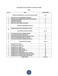
1
MF series In-line / MFI series Insertion
MEMS Mass Flow Meters
SIARGO MEMS FLOW SENSING PRODUCTS
User Manual
(VB.0)
© 2013 Siargo Ltd.
MEMS Mass Flow Meter User Manual
Introduction
The MF series MEMS mass flow meters are the second generation products based
on Siargo's proprietary sensor technology and control circuit technology. These
meters offer a higher standards of intelligent all-electronic mass flow technology.
With the smart software well tested for various applications, the MF series MEMS
mass flow meters achieve high sensitivity, large dynamic range, and high accuracy.
The MF series MEMS mass flow meters incorporate a number of advanced
techniques such as multiple-compensation scheme, noise reduction solution,
multiple signal outputs, and network management feature.
The MF series MEMS mass flow meters can be used for general purpose gas
metering in industry or commercial applications. The user shall observe the general
guidelines in the meter applications in accordance with the safety and other
metrology requirements. It is advised that the user must read this user manual
carefully before processing to field applications. It is mandatory to follow the
instruction of the for installation and operation requirements to ensure the meter
can work properly without malfunctions or even damages.
Declarations
1. Do not alter any software and hardware of the product.
2. Do not use the product if any suspect for malfunction or damage.
3. Do not use this product in any corrosive gas environment.
4. Observe all requirements in accordance with the product specifications.
5. Only qualified personnel from Siargo or a person who is accredited by Siargo
can perform troubleshooting or service to the product.
1
www.Siargo.com
MEMS Mass Flow Meter User Manual
Contents
Introduction
1 Usage and Safety
2 Overview
2.1 Siargo's MEMS Thermal Mass Flow Sensor Technology
2.2 Siargo's MEMS Thermal Mass Flow Meter
3 Working Principle
3.1 Working Principle
3.2 Volume Flow vs. Mass Flow
4 Product Model Selections
4.1 In-line Meters
4.2 Insertion Meters
5 Product Configuration
5.1 In-line Meters
5.2 Insertion Meters
6 Product Specifications
6.1 Physical Dimensions of In-line Meters
6.2 Physical Dimensions of Insertion Meters
6.3 Flow Range of In-line Meters
6.4 Flow Range of Insertion Meters
6.5 Environmental Conditions
6.6 Medium Conditions
6.7 Electrical Specifications
6.8 Other Specifications
7 Installation
7.1 Description of Parts in Package
7.2 Installation Preparation
7.3 Installation Procedure of In-line Meters
7.4 Installation Procedure of Insertion Meters
7.5 Power Up
7.5 Caution Notes on Installation
8 Display and Functions
8.1 Display
8.2 Access Points and User Interface
8.3 Real time display of both flow rate and accumulated volume
8.4 RS485 data communication protocole
8.5 4~20mA Connection
8.6 Pulse Output
8.7 Automatic stored data
8.8 Buttons
9 Safety and Maintenance
9.1 Wetted Materials and Compatibility
9.2 Safety Precautions
10 Maintenance
10.1 Calibration
10.2 Maintenance
11 Warranty
12 Troubleshooting
13 Storage
13.1 Storage
13.2 Transportation
14 Customer Service and Order information
2
1
3
3
4
5
6
7
10
15
18
18
19
19
20
20
www.Siargo.com
MEMS Mass Flow Meter User Manual
1. Usage and Safety
a) The product can be utilized to measure in-line mass flow rate of any relatively clean, single-element gas
or multiple-element gas mixture with a relatively constant concentration profile during gas
measurement, monitoring, or flow control in industrial and commercial applications. If the product is
used for a special gas condition other than listed in above, the product may not function properly or even
can be damaged. Please contact Siargo for special requirements.
b) The operational ranges of the product are illustrated in the section of product specifications. If the product
is used for a special operational condition other than listed in the product specifications, the product may
not function properly or even can be damaged. Please contact Siargo for special requirements.
c) Operation, installation, storage, and maintenance of the product must closely follow the instructions of
this user manual. Otherwise, unpredicted damage and even injuries or other severe situations could be
caused. All the installation, storage, and maintenance of the product must be performed by skilled
workers. This user manual should be placed near the product for easy access.
d) Before using the product, the user should read this user manual completely and in details so that the user
can memorize all the important instructions.
e) It is recommended that the product should be re-calibrated and maintained in every two years or at a
desired time if required.
2. Overview
2.1 Siargo's MEMS Thermal Mass Flow Sensor Technology
Siargo's proprietary MEMS mass flow sensor technology provides accurate in-line flow measurement with
the availability of customer-specified packages. The sensor is manufactured using Siargo's unique MEMS
process that ensures high reliability. The sensors can measure air flow as low as 5 mm/sec and as high as
75m/sec. Depending on the applications, the sensors can be used to measure mass flow, volume flow or
media flow speed. The specially designed circuitry provides amplification as well as small signal processing
capability.
Siargo's flow sensors utilize the thermal mass flow technology using energy balance design. Unlike the other
MEMS flow sensing technologies, Siargo's flow sensors have multiple sensors integrated on a single silicon
chip. The surface of the chip is passivated with ceramic materials of high thermal conductivity to ensure the
sensor's sensitivity. Siargo's sensor package has its flexibility that significantly expands the applications of
the technology.
2.2 Siargo's MEMS Thermal Mass Flow Meter
Siargo's gas meters feature the state-of-the-art electronics that provides a much larger rangeability than
those for most of the thermal mass flow meters using the traditional sensing technology:
Integrated silicon MEMS flow sensors
Measures mass, volume flow and flow speed
Large rangeability over 200:1
Measures flow speed up to 75 m/sec
High stability at full scale
High accuracy and repeatability at full scale
Low power consumption
Low pressure loss
Fast response time
Small form factor
3
www.Siargo.com
MEMS Mass Flow Meter User Manual
3. Working Principle
3.1 Working Principle
Siargo's proprietary MEMS flow meters utilize the insertion sensing approach that can measure gas flows in
a large pipe. The MEMS flow sensor integrates a micro heater, local temperature sensors and environmental
temperature sensors onto a single package. At the no flow, a stable temperature field (distribution) around
the micro heater is maintained. When the flow media passes through the sensor chip, the temperature field
will be forced to change as the flow media will carry away the heat from the micro heater causing the
redistribution and variation of local temperature. Such a change of the local temperature will depend on the
media's mass as well as the media's flow speed. The sensors integrated on the silicon chip will then measure
such temperature redistribution, and the carefully designed signal process circuits and the algorithm
provided by the smart control software can then precisely measure the actual media mass flow. This mass
flow can then be translated into volume speed as well as accumulated volume media consumption at the
specific conditions set at the calibration.
For the MEMS thermal mass flow sensor technology, the heater on the chip has a dimension at the
micrometer scale. In the insertion configuration, the air convection due to the onset of the micro heater is
negligible, and hence the "chimney effect" concerned for most of the "hot-wire" thermal mass flow meters
will not be applicable to the MEMS thermal mass flow sensor technology with this package.
3.2 Volume Flow vs. Mass Flow
For the gas metrology using mechanical meters, the volume flow rate is adopted. The volume rate
nevertheless may not be a good indicator for industrial processing technology as the processing gas quality
depending vastly on the mass, not on the volume. In addition, the volume of gas will change with different
gas temperature and pressure. With the MEMS thermal mass flow meter, it is possible to measure the
"quality" (mass) of the gas directly, and at real time. The mass flow rate will not depend on temperature and
pressure, and hence it accurately measures the actual mass consumption. In addition, the conversion of the
volume rate to the mass rate is readily available by referencing to a standard condition such as at 20 oC and
101.325 kPa.
4
www.Siargo.com
MEMS Mass Flow Meter User Manual
4. Product Model Selections
4.1 In-line Meters
Gas (A - air; C - CO2; N - N2; O - O2; R - Ar;
for other gases, please contact Siargo.)
Output (N- No output; A-4~20mA; B-RS485; D-pulse / 0 ~ 5 V;
Options: B, AB, BD, ABD for external power model;
N for Li-Ion battery model.)
Maximum working pressure (15 - 1.5 MPa )
Maximum flow rate (Nm3/hr. e.g. 450 - 450Nm3/hr)
Minimum flow rate (Nm3/hr. e.g. 2 - 2.0Nm3/hr)
Power supply (D - 3.6VDC Li-Ion battery, E - 12~24VDC external power supply)
Connection (N - NPT; B - BSPT; F - Flange)
DN (Pipe inner diameter, mm. Options: 25, 32, 40, 50, 65, 80, 100)
Product series name
4.2 Insertion Meters
Gas (A - air; C - CO2; N - N2; O - O2; R - Ar;
for other gases, please contact Siargo.)
Output (N- No output; A-4~20mA; B-RS485; D-pulse / 0 ~ 5 V;
Options: B, AB, BD, ABD for external power model;
N for Li-Ion battery model.)
Maximum working pressure (15 - 1.5 MPa )
Probe material (SSS - 304 stainless steel)
Maximum flow rate (Nm3/hr)
Installation (V - with ball valve, D - without ball valve)
Power supply (D - 3.6VDC Li-Ion battery, E - 12~24VDC external power supply)
DN (1 - below DN500, 2 - DN600 ~ DN1100, 3 - above DN1200)
Product series name
5
www.Siargo.com
MEMS Mass Flow Meter User Manual
5. Product Configuration
5.1 In-line Meters
The product consists of MEMS flow sensors, smart control circuitry, display unit and output ports, flow
conditioning set, flange, and other types of connectors. The configuration is illustrated in Fig. 5-1:
Label
User Interface
LCD Display
Smart Control Circuit
Flow Pipe
Flow Direction
Connector (Flange or NPT)
Fig. 5-1
5.2 Insertion Meters
Label
User Interface
LCD Display
Smart Control Circuit
Flow Direction
Sensor Probe
Valve
Sensor
Fig. 5-2
6
www.Siargo.com
MEMS Mass Flow Meter User Manual
6. Product Specifications
6.1 Physical Dimensions of In-line Meters
H
103
n-L
d
D
K
L
Fig. 6-1
Ref . Standards
Model
Connection
DN (mm)
L
H
D
d
K
n-L
MF25
F
25
300
315
115
25
85
4 -φ14
MF32
F
32
300
326
140
32
100
4 -φ18
MF40
F
40
300
330
150
40
110
4-φ18
MF50
F
50
360
344
165
50
125
4-φ18
MF65
F
65
360
362
185
65
145
8-φ18
MF80
F
80
400
374
200
80
160
8-φ18
MF100
F
100
400
396
220
100
180
8-φ18
MF25
N/B
25
300
270
-
25
-
-
MF32
N/B
32
300
272
-
32
-
-
MF40
N/B
40
300
275
-
40
-
-
MF50
N/B
50
360
285
-
50
-
-
GB/T-9116.1-2000
CANSIB1.20.1NPT
or
BSPT:ISO7/1
6.2 Physical Dimensions of Insertion Meters
103
Model
H
D
MFI-1
511
14
MFI-2
586
14
MFI-3
661
19
Fig. 6-2
7
www.Siargo.com
MEMS Mass Flow Meter User Manual
6.3 Flow Range of In-line Meters
Model
Pipe Size(mm)
Max. Flow Rate (Nm3/h)
MF25
25
100
1.0
MF32
32
160
1.6
MF40
40
250
2.5
MF50
50
400
4.0
MF65
65
650
6.5
MF80
80
1000
10
MF100
100
1600
16
Min. Flow Rate (Nm3/h)
6.4 Flow Range of Insertion Meters
Model
Insertion Depth
(mm)
Probe Length(mm)
(H= pipe wall thickness)
80
11
13
168+ H
170+ H
1000
1600
100
MFI-1
MFI-2
MFI-3
Full Length
(mm)
DN
(mm)
Full Scale Flow
(Nm3/hr)
125
16
173+ H
2500
150
20
177+ H
3500
200
26
183+ H
250
33
190+ H
300
40
197+ H
350
46
203+ H
20000
400
53
210+ H
25000
450
60
217+ H
32000
500
66
223+ H
40000
600
80
237+ H
55000
700
93
250+ H
800
106
263+ H
250;D=14;
Ball valve=15
6500
10000
15000
75000
325;D=14;
Ball valve=15
100000
900
119
276+ H
1000
132
289+ H
160000
1100
146
302+ H
200000
1200
159
329+ H
230000
1300
172
343+ H
1400
186
356+ H
1500
199
369+ H
360000
1600
212
382+ H
400000
8
400;D=19;
Ball valve=20
130000
270000
320000
www.Siargo.com
MEMS Mass Flow Meter User Manual
6.5 Environmental Conditions
(1) Temperature: -20 oC~+60 oC
(2) Humidity: ≤95%RH
(3) Atmospheres Pressure: 86kPa~106kPa
(4)Working Pressure: 0.1~ 1.5MPa
6.6 Medium Conditions
(1) Temperature: -10 oC~+55 oC
(2) Gas Type: natural gas, coal gas, etc..; industrial gases except ethane.
6.7 Electrical Specifications
(1)Power supply:
External power model: 12 ~ 24 VDC; 200mA.
Li-Ion battery model: Li-Ion battery L3638A.
(2) Display: Real time LCD display of both flow rate and accumulated rate
(3) Response time: 1 second to 95% of final value
(4) Communication
RS485(Modbus), with real-time data for flow rate and flow accumulation and can be directly
connected to the remote network. A user interface software is an option.
(5) 4 to 20mA output
The current is proportional to the standard mass flow rate; 4mA represents 0 flow rate, while 20mA
corresponds the maximum flow rate Q max.
(6) Pulse output
The output signal consists of a sequence of voltage pulses, each pulse is 0.001Nm 3.
(7) Data records
a) Log of power supply status and accumulated flow rate.
b) As many as 4000 records of the flow status for power supply (the schedule of power-on and -off as
well as the corresponding data of accumulated flow rate.
c) Record the flow accumulation for every 3~720 minutes (which can be programed through the user
interface software) for data analysis and data management. The user interface software can be
obtained from the manufacturer for the desired program and retrieval of the recorded data.
6.8 Other Specifications
(1) Accuracy:
(2) Repeatability:
(3) Turn-Down Ratio:
(4) Working Pressure:
(4) Pressure Loss:
±(1.5+0.5FS)%
±0.75%
> 100:1
1.5MPa
< 500 Pa (at max. flow)
(5) Calibration:
Air (20 oC, 101.325kPa)
(6) Protection:
IP66
(7) Hazard Proof
In-line meters: Ex d IIC T4
Insertion meters: n/a
9
www.Siargo.com
MEMS Mass Flow Meter User Manual
7. Installation
7.1 Description of Parts in Package
When unpack your meter from the shipping container, three parts should be found in the package:
a) The meter
b) This user manual
c) Product certificate
Upon opening the package, the product physical integrity should be inspected to ensure no visual damage
can be observed. If any items are missing or any physical damages are observed, please contact the meter
manufacturer and/or the shipping agent to place a return/exchange or to identify the cause during the
transportation. If you are uncertain of the installation or have any questions about the shipment, please also
contact the manufacturer or the shipping agent before further process.
7.2 Installation Preparation
The product at the time of shipment has been fully inspected for product quality and meets all safety
requirements. Additional safety measures during the installation should be applied. This includes, but is not
limited to leakage verification procedure, standard ESD (electrostatic discharge) precautions, DC voltage
precautions and heavy duty precautions. Other tasks such as calibration, part replacement, repair and
maintenance must only be performed by trained personnel. Upon requests, the manufacturer will provide
necessary technical support and/or training of the personnel.
Do not open the product cover or alter any parts of the product. Any of such actions will forfeit the warranty
and cause the liability to any damages thereafter.
Before the installation, both upstream and downstream valves on the pipeline should be tightly shut down to
ensure no gas leakage from the pipeline. Once the pipeline is ready for installation of the meter, follow the
steps listed below to check the meter electronics:
(1) Check the mechanical integrity including the LCD display and make sure no mechanical faults preexisted before installation.
(2) Connect the cable of the meter (see Fig. 7-1).
Red
Black
Green
Brown
Blue
Purple
Orange
White
Red
Black
Green
Brown
Blue
Purple
Orange
White
DC+, 12-24Vdc supply
Power ground
RS485A
RS485B
LOOP+ (4-20mA output)
LOOP- (4-20mA GND)
Pulse output
Pulse GND
Fig. 7-1
10
www.Siargo.com
MEMS Mass Flow Meter User Manual
(3) In case the cable connection is problematic, user can directly connect the wire to the back
terminal
DCDC+
Power GND
12V~24VDC Power Supply
LP+
LPRS485B
RS485A
GND
VP
PLS
ERR
4~20mA Output
4~20mA GND
For RS485 Communication
For RS485 Communication
Signal GND
NC
PULSE Output
Error Signal Output
Fig. 7-2
For the battery meter, there are three terminals in the back cover. (see Fig. 7-3)
Battery+
BAT+
GND
Battery-
GND
Fig. 7-3
(4) When the above processes are completed, the Fig. 8-1(see page 15) should appeared on the LCD screen;
Attention: Because of the high sensitivity of the meter, the displayed real time flow rate and
accumulated volume value might be non-zero as any air flow passing through the pipe attached to
the meter will be sensed and displayed, regardless if the meter is connected to the pipeline except
that there is absolutely no air flow in the pipe attached. Use your hands or a tight cover to close
both ends of the pipe of the meter, the top line display of the real time flow rate should decrease
and become zero, and the accumulated volume should remain a constant value.
(5) Once the above steps have been performed and no errors are found, it indicates that the meter is working
properly. Then power off the meter by disconnecting the DC cable from the DC outlet, and it is ready to
be installed onto the pipeline. (For battery powered meter, this step can be skipped)
11
www.Siargo.com
MEMS Mass Flow Meter User Manual
7.3 Installation Procedure of In-line Meters
The stainless steel pipe attached to the meter has its both ends with flanges for easy installation. The meter
should be mounted horizontally with the flow direction indicated on the meter body. To ensure the best
performance of the meter, a straight pipe with the same diameter as the pipe attached to the meter and a
length of at least 5D (5 times of the pipe diameter) should be located at the upstream, while another straight
pipe with the same diameter as the pipe attached to the meter and a length of at least 3D should be located at
the downstream, as shown in the following figure:
Meter
Filter
Flow
Fig. 7-4
7.4 Installation Procedure of Insertion Meters
(1). In case of the online installation, make sure there is no any hazardous gases present in the flow
channel, and the proceed to completely close the valves at both upstream and downstream.
(2). Prepare the installation hole in the flow channel (14mm). After the installation hole for the probe on the
flow channel is prepared, make sure there is no any metal particles or other harmful debris present inside
the flow channel. Avoid strong vibration sources.
(3). Attach (by wielding for stainless steel pipeline) the base onto the flow channel, making the hole on the base
align perfectly to that on the flow channel.
(4). Place the O-ring or seal gasket on the base.
Gasket
Cap
Sealer
Valve
Connector
Base
O-ring
Fig. 7-5 Detailed guidance for installation
12
www.Siargo.com
MEMS Mass Flow Meter User Manual
(4). Place the meter in the prepared installation probe hole, make sure the thread or flange can properly seal.
Check the meter position and make sure the probe is perpendicular with respect to the flow channel wall.
H
Calculation of the probe depth, L
L = 157 + H + D/ 8
where H is the flow channel wall thickness
D is the flow channel diameter
A = 1/8 D
L=A+H+157
Fig. 7-6
(5). The flow measurement direction indicated on the meter
should align with the flow direction in the flow channel.
Adjust the probe depth in the flow channel according to
the measurement requirements;
Rotated by 90°
Fig. 7-7
(6). Adjust the direction of the sensor .The sensor surface should be well align with the flow direction inside the
flow channel as illustrated by the graph below. (The sensor surface has been aligned with respect to the
surface where the flow direction arrow rests.)
Use of the Sensor adjustment assistance tool kit may help for a faster sensor
alignment. For further information, please contact manufacturer.
Probe base
Installation
base
Fasten
screw
Sensor adjustment
assistance tool
+3°
Flow direction
-3°
Fig. 7-9
Fig. 7-8 Adjustment of the sensor
13
www.Siargo.com
MEMS Mass Flow Meter User Manual
(7). Fasten the cap.
(8). The meter should be installed avoiding valves, sharp turns and other obstacles possibly presented in the
system for flow instability.
Incorrect installation may
create flow instability
For better performance:
Upstream 20X DN
Downstream 5XDN
Fig. 7-10
7.5 Power Up
After the meter is installed onto the pipeline, follow the steps listed below to finish the installation:
(1) Make sure no leakage at both connections.
(2) Make sure a nearby DC power supply with surge protection is available and the power supply functions
properly without safety issue, other than for a battery powered model.
(3) Connect the DC power cable with the DC power connection of the meter as shown in Fig. 7-1.
(4) Open the valves at both ends of the pipeline until the gas fill the pipeline, then close the valves.
(5) Supply the meter with a proper DC voltage, and the LCD should read as shown in Fig. 8-1 (page 15);
(6) Record the accumulated flow rate value (optional).
(7) Open the valves at both ends of the pipeline, and the meter should then operate as desired.
(8) Finish the installation.
7.6 Caution Notes on Installation
(1) It is forbidden to weld pipeline flange online.
(2) Before installing the flow meter, all the dirty and debris in the pipeline must be cleaned for preventing
possible damages of the product. It is recommended that the pipeline wall should be clean and dry.
(3) Please ensure that the seal rings do not block the passageway of the pipeline.
(4) The ground line of the flow meter must be connected to the earth reliably.
(5) Please ensure that no stress to the flow meter is introduced by the installation.
(6) Near the flow meter site, there should be neither any strong external magnetic field nor any strong
mechanical vibration.
(7) The gas medium should not have strong flow instability. The operation of the valves should be slowly. It
is prohibited to close/open valves abruptly to create extreme pressure pulses.
14
www.Siargo.com
MEMS Mass Flow Meter User Manual
8. Display and Functions
8.1 Display
At the normal operation mode, the meter has the display as shown in Fig 8-1. The Flowrate shows
3
the real time mass flow rate in normal cubic meter per hour (Nm /h); the Total displays the
3
accumulated flow rate in normal cubic meter (Nm ). The conversion of the real time mass flow to
3
the volume is based on the condition that 1 Nm /h equals to the mass that is in 1 cubic meter of the
o
air at a temperature of 20 C and a pressure of 101.325 kPa. The display can only be reset by trained
personnel at the firmware level.
Fig. 8-1
8.2 Access Points and User Interface
Siargo's proprietary flow meter utilizes the insertion approach that can measure gas flows in large
pipes. All access points and user interface are through the cable provided.
8.3 Real time display of both flow rate and accumulated volume
The real time values of both flow rate in normal cubic meters per hour (Nm 3/h) and accumulated
flow rate in normal cubic meters (Nm 3) can be read from the LCD display on the front side of the
meter. The meter can read up to 16 digits to a maximum flow rate record of 99999999.999 normal
cubic meters (Nm 3) and the minimal real time flow rate is 0.001 Nm 3/h.
Alarm code E1~E5 :
E1
E2
E3
E4
E5
Sensor error
Sensor covered with excessive foreign materials
Hardware error
Over flow range
Battery low (battery power model)
Fig. 8-2 Sensor Error
Fig. 8-3 Battery low
15
www.Siargo.com
MEMS Mass Flow Meter User Manual
8.4 RS485 data communication protocole (External Power Model)
For purposes of computer control
following preferred settings:
Baud rate (Bits per second):
Date bits:
Stop bits:
Parity:
Flow control:
and networking, the RS485 is used for communication with the
9600
8
1
None
None
The meter supports two protocols. Protocol A can be used for single meter communications only
while Protocol B is the standard Modbus.
Protocol A
Protocol A can only used for single meter communication and it can be used to access the
meter via the communication port.
Digital communication mode: user can then access the digital data via the port:
a) send 0x9d via RS485 and receive the same returned 0x9d ;
b) send 0x54 via RS485 and receive the same returned 0x54 .
The interval time between two bytes sent to the meter must be longer than 5ms.
The meter will be at Digital communication mode at which the data from the meter will be
sent via RS485 in an interval of 4 seconds. The data are in the following format:
V=vvvvvv\nF=ffffffff\nA=aaaaaaaaaa\nT=t\n;\n;"
vvvvvv:
Voltage code
3
ffffffff:
Flow rate (Equal to fff.fff Nm /h)
3
aaaaaaaaaa:
Accumulated flow (Equal to aaaaa.aaa Nm )
t:
Either shown in 0 or 1
Local display mode: use this mode when only LCD display is needed.
a) send 0x9d via RS485 and receive the same returned 0x9d;
b) send 0x00 via RS485 and receive the same returned 0x00.
The interval time between two bytes sent to the meter must be longer than 5ms.
Then the meter will be at Local display mode at which the data will not be sent via RS485 by
the meter.
Protocol B
Protocol B is based on the standard Modbus communication protocol. It supports either single
meter communication or multi-meter networking. For detailed information, please contact the
manufacturer.
16
www.Siargo.com
MEMS Mass Flow Meter User Manual
8.5 4~20mA Connection (External Power Model)
4~20mA ( LOOP + , Blue )
Input:
24VDC
Output: 4~20 mA
3
( 4mA @ 0 Nm /h; 20 mA@ Max. Flow)
The connection of the loop load resistor is illustrated
as Fig. 8-4:
4~20mA GND ( LOOP - , Violet )
Fig. 8-4
8.6 Pulse Output (External Power Model)
The meter supply pulse output in form of even square wave. The even square wave is composed of
5 V signal high and 0V signal low, and every pulse equal to 1Nm 3, 0.1Nm 3, 0.01Nm 3, 0.001Nm 3 or
3
3
0.0001Nm . (default is 1Nm )
8.7 Automatic stored data
The meter can automatically record mass flow rate, accumulated flow rate and time. To retrieve
these data, please contact manufacturer for the necessary user interface software. The data storage
interval can be customized and please contact manufacturer for further information.
8.8 Buttons
Buttons
Description
FUN
Selection/confirmation of a setting
UP
Scroll up the setup menu
SHIFT
Shift to next item or next bit
FUN
UP
SHIFT
Fig. 8-5
Please contact Siargo for the detailed buttons operations.
17
www.Siargo.com
MEMS Mass Flow Meter User Manual
9. Safety and Maintenance
9.1 Wetted Materials and Compatibility
The meter body and pipe are made of stainless steel. Sensors comprise of silicon, silicon nitride and silicon
dioxide and the sensor surfaces are passivated with silicon nitride and silicon dioxide. The electronic sealing
is provided by RTV (room temperature vulcanizing) #643 Highly Chemical Resistant Coating.
9.2 Safety Precautions
The product is designed for use with general purpose gases such as nitrogen. It is advised that the
products are best used for non-corrosive clean gases unless otherwise packaged. This meter cannot
be used for gas metrology of fluoride or fluoride containing gases. For updates of the product
information, please contact the manufacturer or visit www.Siargo.com. Using for gases that are
extremely corrosive and toxic may cause the product malfunctioning or even severe damages.
The product pressure rating is ensured to work under working pressure of 200 psig and is leakage
proof before the shipment. But cautions and further leakage test are important at installation since
any leakage could cause severe safety issue.
The power supply for this product is 12~24 VDC, all precautions and measures for electrical
voltage handling must apply.
Attentions: any alternation and/or improper use of the product without the permission of the
manufacturer can cause unpredicted damage and even injuries or other severe situations.
Siargo Ltd. or any of its employees and subsidiaries shall not be held liable and indemnified
against consequences due to such circumstances via improper use of the product.
10. Maintenance
10.1 Calibration
The meter at the time of shipping is fully calibrated at the conditions indicated on the product label. Use of
the product under other conditions will lead to unpredictable results. Please contact the manufacture before
proceeding to such applications.
To ensure the meter performance, the meter should be calibrated every 12 to 24 months.
10.2 Maintenance
Attention: without prior permission of the manufacturer, please do not attempt to alter any parts of the product
as it may cause unrecoverable damages. If there are any questions or doubts, please contact manufacturer
immediately before further actions. Please ensure the DC power is off before dismounting the meter from the
installation.
All maintenance of the sensor should be done from trained and certified personnel by Siargo Ltd.
18
www.Siargo.com
MEMS Mass Flow Meter User Manual
11. Warranty
(Effective September 2005)
Siargo warrants the products sold hereunder, properly used and properly installed under normal circumstances
and service as described in the user's manual, shall be free from faulty materials or workmanship for 180 days
for OEM products, and 365 days for non-OEM products from the date of shipment. This warranty period is
inclusive of any statutory warranty. Any repair or replacement serviced product shall bear the same terms in this
warranty.
Siargo makes no other warranty, expressed or implied and assumes no liability for any
special or incidental damage or charges, including but not limited to any damages or
charges due to installation, dismantling, reinstallation or any other consequential or
indirect damages of any kind. To the extent permitted by Law, the exclusive remedy of the
user or purchaser, and the limit of Siargo s liability for any and all losses, injuries or
damages concerning the products including claims based on contract, negligence, tort,
strictly liability or otherwise shall be the return of products to Siargo, and upon
verification by Siargo to prove to be defective, at its sole option, to refund, repair or
replacement of the products. No action, regardless of form, may be brought against Siargo
more than 365 days after a cause of action has accrued. The products returned under warranty
to Siargo shall be at user or purchaser's risk of loss, and will be returned, if at all, at
Siargos risk of loss.
Purchasers or users are deemed to have accepted this limitation of warranty and liability,
which contains the complete and exclusive limited warranty of Siargo, and it shall not be
amended, modified or its terms waived except by Siargos sole action.
This warranty is subject to the following exclusions:
1. Products that have been altered, modified or have been subject to unusual physical or
electrical circumstances indicated but not limited to those stated in the users manual or
any other actions which cannot be deemed as proper use of the products.
2. Siargo does not provide any warranty on finished goods manufactured by others. Only the original
12. Troubleshooting
Errors
Possible causes
Actions
No display
1. Wrong wire connection
2. LCD malfunction
1. Follow user manual, reconnect the wires
2. Check the LCD connection, otherwise replace
Display nonzero while no gas
flow in the pipe
1. Valve may not be closed completely
2. Pipe leakage
1. Check valve and perform leak tests
2. Check meter offset
No flow reading
1. Power supply error
2. Sensor damaged
1. Check power source
2. Check sensor error code, replace sensor
Flow rate drops
1. Flow channel clogging
2. Foreign materials deposit on sensor
1. Check and/or change pipe filter
2. Clean or change sensor
Communication malfunction
1. Wrong wire connection
2. Wrong baud rate
3. Pin contact error
1. Check wire connections
2. Check baud rate settings
3. Check hardware connections/contacts
No 4-20mA output
1. Wrong wire connection
1. Reconnect the wires
No pulse output
1. Wrong wire connection
1. Reconnect the wires
For other errors or additional information, please contact the manufacturer.
19
www.Siargo.com
MEMS Mass Flow Meter User Manual
13. Storage
13.1 Storage
The products if not being installed upon receiving, should be stored in an area without the
presence of strong chemicals, electromagnetic interference and vibration. The
environments should be dry (<95%RH) and the temperature should be in the range of -25
to 80C.
13.1 Transportation
During transportation, the products should be properly packaged if not being placed in
their original package containers. Such package should be able to resist vibration.
14. Customer Service and Order information
Siargo Ltd. is making every effort to ensure the quality of the products. In case of questions, and or product
supports, please contact customer service at the address listed below. We will respond your request in a
timely fashion and will work with you toward your complete satisfaction.
Customer service and all orders should be addressed to
Siargo Ltd.
2041 Mission College Blvd., Suite 250
Santa Clara, CA 95054.
Tel:
01-(408)969-0368
Email:
[email protected].
For orders, please provide accurate and full post address. Siargo will not ship to P.O. Boxes or via a third
party.
For further information and updates, please visit www.Siargo.com.
20
www.Siargo.com
Siargo Ltd.
2041 Mi ssion Co llege Blvd, Ste 250
Santa Cl ara, CA 95054 US A
Tel:+1(408)969-0368
Ema il: Info@Si argo.com
Ht tp: //ww w. Siargo.com