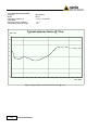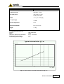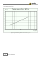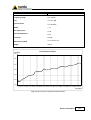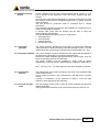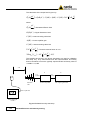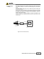
1
NARDA Safety Test Solutions S.r.l. Socio Unico Sales & Support: Via Leonardo da Vinci, 21/23 20090 Segrate (MI) - ITALY Tel.: +39 02 2699871 Fax: +39 02 26998700 Manufacturing Plant: Via Benessea, 29/B 17035 Cisano sul Neva (SV) Tel.: +39 0182 58641 Fax: +39 0182 586400 http://www.narda-sts.it User’s Manual PMM AS02 PMM AS03 ANTENNA SYSTEM SERIAL NUMBER OF THE INSTRUMENT You can find the Serial Number near the RF connector on both antennas. Serial Number is in the form: 0000X00000. The first four digits and the letter are the Serial Number prefix, the last five digits are the Serial Number suffix. The prefix is the same for identical instruments, it changes only when a configuration change is made to the instrument. The suffix is different for each instrument. Document AS0203EN-90606 - Copyright © NARDA 2009 NOTE: If the instrument is used in any other way than as described in this Users Manual, it may become unsafe Before using this product, the related documentation must be read with great care and fully understood to familiarize with all the safety prescriptions. To ensure the correct use and the maximum safety level, the User shall know all the instructions and recommendations contained in this document. This product has a Pollution Degree II normally only non-conductive pollution occurs. Occasionally, however, a temporary conductivity caused by condensation must be expected. The information contained in this document is subject to change without notice. KEY TO THE ELECTRIC AND SAFETY SYMBOLS: You now own a high-quality instrument that will give you many years of reliable service. Nevertheless, even this product will eventually become obsolete. When that time comes, please remember that electronic equipment must be disposed of in accordance with local regulations. This product conforms to the WEEE Directive of the European Union (2002/96/EC) and belongs to Category 9 (Monitoring and Control Instruments). You can return the instrument to us free of charge for proper environment friendly disposal. You can obtain further information from your local Narda Sales Partner or by visiting our website at www.narda-sts.it . Warning, danger of electric shock Earth Read carefully the Operating Manual and its instructions, pay attention to the safety symbols. Unit Earth Connection Earth Protection Equipotential KEY TO THE SYMBOLS USED IN THIS DOCUMENT: The DANGER sign draws attention to a potential risk to a person’s safety. DANGER All the precautions must be fully understood and applied before proceeding. WARNING The WARNING sign draws attention to a potential risk of damage to the apparatus or loss of data. All the precautions must be fully understood and applied before proceeding. CAUTION The CAUTION sign draws attention against unsafe practices for the apparatus functionality. NOTE: II The NOTE draw attention to important information. Note and symbols Contents 1 General information 1.1 Introduction................................…............................… 1.2 Documentation….......................................................... 1.3 Introduction to the PMM AS02/AS03 Antenna System. 1.4 Standard accessories.…………………………………… 1.5 Optional accessories………………………………......... 1.6 PMM BC-01 Biconical Dipole Antenna…………………. 1.7 PMM LP-02 Log Periodic Dipole Array…………………. 1.8 PMM LP-03 Log Periodic Dipole Array…………………. 1.9 Main Specifications………………………………………. Page 1-1 1-1 1-1 1-2 1-2 1-3 1-3 1-4 1-5 2 Mounting Instructions 2.1 Introduction………………………………………………… 2.2 Initial inspection…………………………………………… 2.3 Environment……………………………………………….. 2.4 Return for service…....................................................... 2.5 Equipment cleaning……………………………………..… 2.6 PMM BC01 Biconical Dipole.......................................... 2.7 PMM LP02 Log Periodic Dipole Array.......................…. 2.8 PMM LP-03 Log Periodic Dipole Array ……………….... 2.8.1 PMM LP-03 stand alone……………………………….. 2.8.2 PMM LP-03 with PMM 9060…………………………... Page 2-1 2-1 2-1 2-1 2-1 2-2 2-3 2-4 2-4 2-6 3 Radiated Emission and Immunity testing 3.1 Radiated emission testing..........................................… 3.1.1 The receiver antenna…………………………………… 3.1.2 The interconnecting cable……………………………… 3.1.3 The preamplifier………………………………………… 3.1.4 The preamplifier interconnecting cable………………. 3.1.5The meter receiver……………………………………… 3.2 Radiated immunity testing.........................................…. 3.2.1 The signal generator…………………………………… 3.2.2 The power amplifier……………………….…………… 3.2.3 The transmit antenna………………………………….. 3.2.4 The field strength meter………………………………. 3.3 Environmental testing…………………………………….. Page 3-1 3-1 3-1 3-1 3-1 3-2 3-3 3-3 3-3 3-3 3-3 3-5 Contents III Figures Figure 1-1 1-2 1-3 1-4 1-5 1-6 1-7 1-8 1-9 1-10 1-11 1-12 1-13 1-14 2-1 2-2 2-3 2-4 3-1 3-2 3-3 Page PMM AS02/AS03 kit…………………………………………. PMM BC-01…………………………………………………... PMM LP-02…………………………………………………… PMM LP-03…………………………………………………… Typical BC01 biconical antenna factor @ 3 m……........... Typical BC01 biconical antenna factor @ 10 m……......... Typical LP02 Log Periodic antenna factor @ 3 m…..….... Typical LP02 Log Periodic antenna factor @ 10 m…….... Typical LP03 Log Periodic antenna factor …………..….... Typical Gain LP-03….……………………………….……… Typical VSWR LP-03…..…………………………….……... Mounting head with center column.................................... Adjustable joint……..………………………………….……. Typical RF Cable/5 insertion loss...…………………….… PMM BC-01 with TR01………...…………………………… PMM LP-02 with TR01………...…………………………… PMM LP-03 with TR01………...…………………………… PMM LP-03 with PMM 9060….…………………………… Radiated emission test setup……………………………… Radiated immunity test setup……………………………… Environmental test setup…………………………………… 1-1 1-3 1-3 1-4 1-5 1-6 1-7 1-8 1-9 1-10 1-10 1-11 1-11 1-12 2-2 2-3 2-5 2-7 3-2 3-4 3-5 Tables Table 1-1 1-2 1-3 1-4 1-5 Page PMM BC01 Biconical Dipole Specifications...................... PMM LP02 Log Periodic Dipole Array Specifications........ PMM LP03 Log Periodic Dipole Array Specifications........ PMM TR01 Wooden Tripod Specifications……………….. PMM RF Cable / 5 Specifications………………………….. IV Contents 1-5 1-7 1-9 1-11 1-12 1 – General Information 1.1 Introduction This manual is a guide to the installation and use of the PMM AS02/AS03 Antenna System. Main information about the radiated emission and immunity testing are also explained. 1.2 Documentation Enclosed with this manual are: • a service questionnaire to send back to NARDA if equipment service is required. • an accessories check list to verify all accessories enclosed in the packaging. 1.3 Introduction to the PMM AS02/AS03 Antenna System With a compact size, easy mounting system and polarization change, light weight and broadband frequency range the Antenna System is the ideal solution for automated measurements in the 30 MHz to 3 GHz (PMM AS02) and in the 30 MHz to 6 GHz (PMM AS03) frequency range. Common applications include measurements to EN55022 emission and IEC 1000-4-3 immunity testing specifications. The PMM AS02/AS03 is a compact size broadband Antenna System composed of a PMM BC-01 Biconical Dipole, PMM LP-02 Log Periodic Dipole Array and PMM LP-03 Log Periodic Dipole Array (for PMM AS03 only). The tripod PMM TR01 is highly recommended; the tripod stand is made by hard wood assuring the needed rigidity when holding the antenna, the adjustable joint allows easy to mount and antenna polarization change operations. Fig. 1-1 PMM AS02/AS03 kit Document AS0203EN-90606 - © NARDA 2009 General information 1-1 1.4 Standard Accessories The Antenna System includes the following: • BC01 - Biconical Dipole Antenna • LP02 - Log Periodic Dipole Array • LP03 - Log Periodic Dipole Array (for PMM AS03 only) • Support for LP-03 (for PMM AS03 only) • CC01 – Soft Carrying case • CC03 – Soft Carrying case (for PMM AS03 only) • TR01 - Wooden tripod with extension and adjustable joint • RF Cable/5 - RF cable (5m long) • Antenna Certificates BC-01 • Antenna Certificates LP-02 • Antenna Certificates LP-03 (for PMM AS03 only) • Return for Repair Form • Operating Manual 1.5 Optional Accessories The following accessories can be ordered separately: • BC01 - Biconical Dipole Antenna • LP02 - Log Periodic Dipole Array • LP03 - Log Periodic Dipole Array • PMM TR01 Wooden tripod; • RF Cable/5 - RF cable (5 m long) 1-2 General information 1.6 PMM BC-01 Biconical Dipole Antenna The PMM BC-01 Biconical Dipole is a compact size and time saving alternative to the classical dipole antenna in the range 30 - 200 MHz; the tedious manual adjustment at each frequency of the classical dipole elements can be avoided using the compact size and broadband frequency range characteristics of the PMM AS02 Biconical Dipole element design. Fig. 1-2 PMM BC-01 The PMM BC-01 can be ordered separately and includes: • Soft Tubular Case; • Calibration Report; • Operating Manual; • Return for Repair Form. The optional accessories: • PMM TR01 Wooden tripod; • RF Cable/5 - RF cable (5 m long) 1.7 PMM LP-02 Log Periodic Dipole Array The PMM LP02 Log Periodic Dipole Array obtain a broadband excellent VSWR characteristics thanks to its accurate design of the feed and elements positioning on the boom, the constant antenna gain yields an antenna factor which varies linearly with frequency in the range 200 MHz to 3 GHz. Fig. 1-3 PMM LP-02 The PMM LP-02 can be ordered separately and includes: • CC01 - Antenna System carrying case; • Calibration Report; • Operating Manual; • Return for Repair Form. The optional accessories: • PMM TR01 Wooden tripod; • RF Cable/5 - RF cable (5 m long) General information 1-3 1.8 PMM LP-03 Log Periodic Dipole Array The PMM LP03 Log Periodic Dipole Array obtain a broadband excellent VSWR characteristics thanks to its accurate design of the feed and elements positioning on the boom, the constant antenna gain yields an antenna factor which varies linearly with frequency in the range 0.8 to 6 GHz. The PMM LP-03 has been developed and specified mainly as accessory of the 6 GHz receivers 9060. The LP03 can be also offered as a general purpose antenna for both EMC and other industrial applications, alone or in an antenna kit (PMM AS-03). The booms and the elements are made of aluminium Alodyne coated and painted; the holding pipe is made of stainless steel; the antenna is composed by a total of 28 elements. The LP03 combines small size with high manufacturing and calibration standards, making it perfectly suitable for portable applications and in anechoic chambers. The tripod PMM TR01 is highly recommended; the tripod stand is made by hard wood assuring the needed rigidity when holding the antenna, the adjustable joint allows easy to mount and antenna polarization change operations. Fig. 1-4 PMM LP-03 The PMM LP-03 can be ordered separately and includes: • Support for LP-03; • CC03 Soft Carrying Case; • Calibration Report; • Operating Manual; • Return for Repair Form. The optional accessories: • PMM TR01 Wooden tripod; The antenna is configured with Nm connector matching with 90xx series RF input connector. For the antenna standard connector is Nf, an optional accessory Nf to Nf adapter is supplied with. 1-4 General information The following Tables list the Antenna performance specifications. 1.9 Main Specifications TABLE 1-1 PMM BC01 Biconical Dipole Specifications Electrical characteristics Performance Limits Frequency range 30 - 200 MHz Max input power 100 W Nominal Impedance 50 Ω Connector N-Female Dimensions WxHxP 137 x 65 x 65 cm Weight 1,8 Kg 3 m Typical Antenna Factor Antenna Model Calibration Distance & Polarisation Receiving Antenna Height Transmitting Antenna Height BICONICAL BC 01 3,0 m Horizontal 1-4 m 1m Typical antenna factor @ 3 m (dB 1/m) 20 18 16 14 12 10 8 6 4 2 0 30 40 50 60 70 80 90 100 110 120 130 140 150 160 170 180 190 200 Freq. (MHz) Fig. 1-5 Typical BC01 biconical antenna factor @ 3 m General information 1-5 10 m Typical Antenna Factor Antenna Model Calibration Distance & Polarisation Receiving Antenna Height Transmitting Antenna Height BICONICAL BC 01 10,0 m Horizontal 1-4 m 1m Typical antenna factor @ 10 m (dB 1/m) 20 18 16 14 12 10 8 6 4 2 0 30 40 50 60 70 80 90 100 110 120 130 140 150 160 170 180 190 200 Freq. (MHz) Fig. 1-6 Typical BC01 biconical antenna factor @ 10 m 1-6 General information TABLE 1-2 PMM LP02 Log Periodic Dipole Array Specifications Electrical characteristics Performance Limits Frequency range 200 MHz - 3 GHz Max input power 100 W up to 1 GHz 50 W up to 3 GHz VSWR < 2:1 (1,2:1 average) Gain (Average) + 6 dB Nominal Impedance 50 Ω Dimensions WxHxP 86 x 10 x 70 cm Weight 1,1 Kg 3 m Typical Antenna Factor Antenna Model Calibration Distance & Polarisation Receiving Antenna Height Transmitting Antenna Height LOG PERIODIC LP 02 3,0 m Horizontal 1-4 m 1m Typical antenna factor @ 3 m (dB 1/m) 50 45 40 35 30 25 20 15 10 5 0 100 1000 10000 Freq. (MHz) Fig. 1-7 Typical LP02 Log Periodic antenna factor @ 3 m General information 1-7 10 m Typical Antenna Factor Typical antenna factor @ 10 m (dB 1/m) 50 45 40 35 30 25 20 15 10 5 0 100 1000 10000 Freq. (MHz) Fig. 1-8 Typical LP02 Log Periodic antenna factor @ 10 m 1-8 General information TABLE 1-3 PMM LP-03 Log Periodic Dipole Array Specifications Electrical characteristics Performance Limits Frequency range 0.8 - 6 GHz Gain 3.5 ÷ 6.5 dBi Antenna factor 23 / 42 dB/m VSWR < 1.7 Max input power 75 W Nominal Impedance 50 Ω Connector N-male Dimensions LxHxP 19 x 2 x 32.5 cm Weight 250 gr AF (dB/m) LP-03 Antenna Factor 50.0 45.0 40.0 35.0 30.0 25.0 700 800 900 1000 1100 1200 1300 1400 1500 1600 1700 1800 1900 2000 2100 2200 2300 2400 2500 2600 2700 2800 2900 3000 3100 3200 3300 3400 3500 3600 3700 3800 3900 4000 4100 4200 4300 4400 4500 4600 4700 4800 4900 5000 5100 5200 5300 5400 5500 5600 5700 5800 5900 6000 6100 20.0 Freq. (MHz) Fig. 1-9 Typical LP03 Log Periodic antenna factor General information 1-9 700 800 900 1000 1100 1200 1300 1400 1500 1600 1700 1800 1900 2000 2100 2200 2300 2400 2500 2600 2700 2800 2900 3000 3100 3200 3300 3400 3500 3600 3700 3800 3900 4000 4100 4200 4300 4400 4500 4600 4700 4800 4900 5000 5100 5200 5300 5400 5500 5600 5700 5800 5900 6000 6100 700 800 900 1000 1100 1200 1300 1400 1500 1600 1700 1800 1900 2000 2100 2200 2300 2400 2500 2600 2700 2800 2900 3000 3100 3200 3300 3400 3500 3600 3700 3800 3900 4000 4100 4200 4300 4400 4500 4600 4700 4800 4900 5000 5100 5200 5300 5400 5500 5600 5700 5800 5900 6000 6100 Gain (dB) LP03 Gain 10.0 9.0 8.0 7.0 6.0 5.0 4.0 3.0 2.0 1.0 0.0 Freq. (MHz) Fig. 1-10 Typical Gain LP-03 VSWR LP03 VSWR 4 3 2 1 Freq. (MHz) Fig. 1-11 Typical VSWR LP-03 1-10 General information TABLE 1-4 PMM TR01 Wooden tripod with extension and adjustable joint Specifications Characteristics Performance Limits • legs 3 legs x 3 sections extensible • transportation width: 76 x 12 x 12 cm • 60 cm minimum height: • maximum height: 180 cm • weight 2,8 kg • load capacity: 10 kg Fig. 1-12 Mounting head with center column It is possible to adjust legs spread at tree different angles, the adjustment is made rotating the knurled locking adjuster by selecting the corresponding marker on the knurled locking adjuster: • 20° spread : knurled locking adjuster white mark; • 45° spread : knurled locking adjuster red mark; • variable spread : knurled locking adjuster unmarked. The central mast can be adjusted and fixed with the clamping lever. Fig. 1-13 Adjustable joint • Height: 7 cm • Weight: 180 g • Load capacity: 10 kg The adjustable joint allows to easily mount the antennas on the center column of the tripod and to change the antenna polarization from horizontal to vertical or vice versa. General information 1-11 TABLE 1-5 PMM RF Cable/5 - 5 m long RF cable Specifications Electrical characteristics Performance Limits Connectors N-Male Max Power input 300 W up to 200 MHz 100 W up to 3 GHz Length 5m Weight 850 g CH1 S21 log MAG .5 dB/ 31 Jan 2000 13:01:43 REF 0 dB 4_:-2.5 dB 2 700.000 000 MHz PRm Cor Avg 16 1_:-.2 dB 30 MHz SCALE 1 .5 dB/div 2_:-.5 dB 200 MHz 2 3_:-1.3 dB 1 GHz 3 4 START 10.000 000 MHz STOP 3 000.000 000 MHz Fig. 1-14 Typical RF Cable/5 insertion loss 1-12 General information 2 – Mounting Instructions 2.1 Introduction This section provides the information needed to install and use your PMM AS02/AS03 Antenna System. Included are information pertinent to initial inspection, interconnection, environment, mechanical mounting, cleaning, storage and shipment. 2.2 Initial inspection Inspect the shipping container for damage. If the shipping container or cushion material is damaged, it should be kept until the contents of the shipment have been checked for completeness and the antennas have been checked mechanically and electrically. Verify the accessories availability in the shipping referring to the accessories check list enclosed. Notify any damage to the carrier personnel as well as the NARDA Representative. 2.3 Environment The PMM AS02/AS03 Antennas are constructed of lightweight corrosionresistant aluminum providing years of indoor and outdoor service. 2.4 Return for service If the Antenna System should be returned to NARDA for service, please complete the service questionnaire enclosed with the Users Manual and attach it to the instrument. To minimize the repair time, be as specific as possible when describing the failure. If possible, reuse of the original packaging to ship the equipment is preferable. In case other package should be used, ensure to wrap the instrument in heavy paper or plastic. Use a strong shipping container and use enough shock absorbing material around all sides of the equipment to provide a firm cushion and prevent movement in the container. Seal the shipping container securely. Mark the shipping container FRAGILE to encourage careful handling. 2.5 Equipment cleaning Use a clean, dry, non abrasive cloth for equipment cleaning. To clean the wooden tripod do not use any solvent, thinner, turpentine, acid, acetone or similar matter to avoid damage to it. Document AS0203EN-90606 - © NARDA 2009 Mounting Instruction 2-1 2.6 PMM BC01 Biconical Dipole Screw the radiating elements on the conical fastening of the BICONICAL Antenna, the radiating elements are all of equal length. Unscrew the knob without to loose it completely. Insert the tripod joint on the adjustable joint. Change the antenna polarization from horizontal to vertical or vice versa and tighten the knob completely. Fig. 2-1 PMM BC-01 with TR01 2-2 Mounting Instruction 2.7 PMM LP-02 Log Periodic Dipole Array Screw the radiating elements on the main body of the LOG PERIODIC Antenna, choosing the radiating elements couple of equal length. The antenna is composed by a total of 44 elements, only the longer 14 elements are removable. Start screwing the shortest couple on the front side of the antenna, going on installing growing length elements on the connector side. Unscrew the knob without to loose it completely. Insert the tripod joint on the adjustable joint. Change the antenna polarization from horizontal to vertical or vice versa and tighten the knob completely. Fig. 2-2 PMM LP-02 with TR01 Mounting Instruction 2-3 2.8 PMM LP-03 The LP03 combines small size with high manufacturing and calibration standards, making it perfectly suitable for portable applications and in anechoic chambers. The booms and the elements are made of aluminium Alodyne coated and painted; the holding pipe is made of stainless steel; the antenna is composed by a total of 28 elements. 2.8.1 PMM LP-03 stand alone Fix the adjustable joint to the TR01. Remove the screws from the tripod joint. Insert the LP-03 on the tripod joint and tighten the two screws to fix the LP03 to the tripod join. 2-4 Mounting Instruction Unscrew the knob without to loose it completely. Insert the tripod joint on the adjustable joint. Change the antenna polarization from horizontal to vertical or vice versa and tighten the knob completely. Fig. 2-3 PMM LP-03 with TR01 Mounting Instruction 2-5 2.8.2 PMM LP-03 with PMM 9060 In order to perfectly match antennas to PMM 9060, a dedicated PVC Antenna Holder is also provided as a PMM 9060 standard accessory, so balancing weight between receiver and antenna when attached to a tripod or antenna mast. Such Antenna Holder comes with some spare parts plus nuts and bolts, which can be easily assembled with provided wrench, as per step-by-step operations in following pictures: Mounting the Tripod joint Mounting the Antenna Holder on PMM 9060 2-6 Mounting Instruction Fixing onto the Tripod Attaching PMM LP-03 Log Periodic Change the PMM 9060 polarization from horizontal to vertical or vice versa and tighten the knob completely. Fig. 2-4 PMM LP-03 with PMM 9060 For further information on configuration and operation with PMM 9060, please refer to the operation manual supplied with it. Mounting Instruction 2-7 This page has been left blank intentionally 2-8 Mounting Instruction 3 - Radiated Emission and Immunity testing 3.1 Radiated Emission testing During a radiated emission test the electromagnetic emissions emanating from the equipment under test (EUT) are measured. According to the international Standards, the purpose of this test is to verify that the EUT's radiated electromagnetic emissions are below specified limits during operation. The receiving antenna middle point can be located either at 3 or 10 meter from the EUT and must scan from 1 to 4 meters in height. This scanning helps the operator to locate the EUT's worst case electromagnetic emission level. The typical emissions test system set-up is composed of: • receive antenna; • interconnecting cable; • preamplifier; • preamplifier cable; • meter receiver. 3.1.1 The Receive Antenna The performance measure of the antenna relating to the value of the incident E-Field to the voltage output of the antenna is the Antenna Factor. This is usually provided by the manufacturer in dB with units of inverse meters. Typically a combination of two or more antennas is used to cover the wide frequency range required by the Standard, from 30 to 2000 MHz and over. The BC-01 Biconical dipole covering the frequency range of 30 to 200 MHz, the PMM LP-02 Log periodic covering the frequency range of 200 MHz to 3 GHz and the PMM LP-03 Log periodic covering the frequency range of 800 MHz to 6 GHz. 3.1.2 The interconnecting cable The cable connects the antenna to the preamplifier or meter receiver input. There is a loss in the cable resulting in a reduction of the measured signal, to increase the measure accuracy, these losses need to be added to the measured value. 3.1.3 The preamplifier If the Receiver or the Spectrum Analyzer have an high input noise figure, may be necessary to compensate it with a preamplifier installed between the antenna and the meter receiver. The preamplifier makes the measured signal larger, thus the gain of the preamplifier must be subtracted from the measured value to obtain the correct final result. 3.1.4 The preamplifier interconnecting cable An additional cable to connect the preamplifier to the meter receiver input may be necessary if the preamplifier is installed. There is a loss in the cable resulting in a reduction of the measured signal, to increase the measure accuracy, these losses need to be added to the measured value. Document AS0203EN-90606 - © NARDA 2009 Radiated Emission and Immunity testing 3-1 3.1.5 The meter receiver The meter receiver is typically either a radio receiver or a spectrum analyzer. Either a 120 kHz bandwidth and an output indication calibrated in dBµV are required. The calculation of the measured E-field signal level is given by: 1⎞ ⎛ µV ⎞ ⎛ E ⎜ dB ⎟ = S (dBµV ) + C1 (dB ) − PA(dB ) + C2 (dB ) + AF ⎜ dB ⎟ m ⎠ ⎝ ⎝ m⎠ where: ⎛ µV ⎞ E ⎜ dB ⎟ =Corresponding Electric field m ⎠ ⎝ S (dBµV ) = Measured signal strength C1 (dB ) = Preamplifier interconnecting cable PA(dB ) = Preamplifier gain C2 (dB ) = Interconnecting cable loss 1⎞ ⎛ AF ⎜ dB ⎟ = Antenna factor ⎝ m⎠ 3 or 10 m S C1 C a b le PA C2 C a b le EU T Pre a m p lifie r An te n n a AF Fig. 3-1 Radiated emission test setup 3-2 Radiated Emission and Immunity testing R e ce ive r o r Sp e ctru m An a lyze r 3.2 Radiated Immunity testing During a radiated immunity test a electromagnetic signal, typically 3 or 10 V/m is directed at the equipment under test (EUT), analyzing the EUT reaction. According to the international Standards, the purpose of this test is to verify that the EUT doesn't show any degraded performance or failure when the signal is applied. The test should be performed either in horizontal and in vertical polarization. The transmitting antenna and the EUT are installed into a shielded room to avoid environmental RF pollution. A isotropic field probe must be located near the EUT to verify the electromagnetic field strength. The typical radiated test system set-up is composed of: • signal generator; • power amplifier; • transmit antenna; • field strength meter. 3.2.1 The signal generator The signal generator provides the test signal. It should have adequate output resolution to allow the setting of the field strength to within 1% of the desired level and must provide a sine wave 80% AM modulation at 1 kHz. 3.2.2 The power amplifier The power amplifier is used to increase the test signal strength applied to the antenna to a level able to produce the desired E-field. Note that the EMC amplifiers are specified with a minimum gain, they can show several dB of ripple in the pass band. The power amplifier must be operated in linear mode to assure repeatability, in fact when a 80% AM modulation is added an additional 5.1 dB ⎧ ⎫ ⎨ 20 x log10 (1.8) ⎬ of linear gain from the power amplifier is required. ⎩ ⎭ 3.2.3 The transmit antenna The performance of the antenna relating to the value of the emitted E-Field is the Antenna Factor. This is usually provided by the manufacturer in dB with units of inverse meters. Typically a combination of two antennas is used to cover the wide frequency range required by the Standard. 3.2.4 The field strength meter The field strength meter probe is used to directly measure the field level applied to the EUT. The typical distance between the tip of the antenna and the probe is 3 m. Radiated Emission and Immunity testing 3-3 The calculation of the output level is given by: ⎛ µV E ⎜ dB m ⎝ 1⎞ ⎞ ⎛ ⎟ = G (dBµV ) − C1 (dB ) + A(dB ) − C2 (dB ) + TAF 3m ⎜ dB ⎟ ⎠ ⎝ m⎠ where: ⎛ µV ⎞ E ⎜ dB ⎟ =Generated Electric field m ⎠ ⎝ G (dBµV ) = Signal Generator Level C1 (dB ) = Interconnecting cable loss A(dB ) = Power amplifier gain C2 (dB ) = Interconnecting cable loss 1⎞ ⎛ TAF 3m ⎜ dB ⎟ = Transmit Antenna factor at 3 m = ⎝ m⎠ 1⎞ ⎛ 20 log10 ( f MHz ) − AF 3m ⎜ dB ⎟ − 41,5 ⎝ m⎠ The variables and terms in the above expression are used for calibration test setup only. They demonstrate how the instrumentation and facility factors contribute to meet the typically required E-field uniformity value of -0.0 dB to + 6,0 dB. 3m A C2 C a b le An te n n a TAF G C1 C a b le Po w e r am p lifie r Fib e r o p tic lin k Fie ld s tren g th m e te r Fig. 3-2 Radiated immunity test setup 3-4 Radiated Emission and Immunity testing R F s ig na l g e ne ra to r 3.3 Environmental testing The PMM LP02/LP03 Log Periodic antenna can also be used on environmental testing for narrow band electromagnetic field exposure testing. The wide frequency range and the low VSWR both allow accurate tests with linear polarization. For this kind of test the antenna must be used according to the following test setup, the receiver must have a good selectivity performance and must be tunable on the frequency or frequencies under investigation, a spectrum analyzer can be used instead. The RF attenuator is normally installed as closest as possible to the antenna to improve the VSWR performances and then the precision of the measurement. C a b le C a b le R F a tte n u a to r An te n n a R e ce ive r o r Sp e ctru m An a lyze r Fig. 3-3 Environmental test setup Radiated Emission and Immunity testing 3-5 This page has been left blank intentionally 3-6 Radiated Emission and Immunity testing NARDA Safety Test Solutions S.r.l. Socio Unico Sales & Support: Via Leonardo da Vinci, 21/23 20090 Segrate (MI) - ITALY Tel.: +39 02 2699871 Fax: +39 02 26998700 Manufacturing Plant: Via Benessea, 29/B 17035 Cisano sul Neva (SV) Tel.: +39 0182 58641 Fax: +39 0182 586400 http://www.narda-sts.it Mod. 18-1 Caro cliente grazie per aver acquistato un prodotto NARDA! Sei in possesso di uno strumento che per molti anni ti garantirà un’alta qualità di servizio. NARDA riconosce l'importanza del Cliente come ragione di esistenza; ciascun commento e suggerimento, sottoposto all'attenzione della nostra organizzazione, è tenuto in grande considerazione. La nostra qualità è alla ricerca del miglioramento continuo. Se uno dei Suoi strumenti NARDA necessita di riparazione o calibrazione, può aiutarci a servirla più efficacemente compilando questa scheda e accludendola all’apparecchio. Tuttavia, anche questo prodotto diventerà obsoleto. In questo caso, ti ricordiamo che lo smaltimento dell'apparecchiatura deve essere fatto in conformità con i regolamenti locali. Questo prodotto è conforme alle direttive WEEE dell’Unione Europea (2002/96/EC) ed appartiene alla categoria 9 (strumenti di controllo). Lo smaltimento, in un ambiente adeguato, può avvenire anche attraverso la restituzione del prodotto alla NARDA senza sostenere alcuna spesa. Può ottenere ulteriori informazioni contattando i venditori NARDA o visitando il nostro sito Web www.narda-sts.it. Dear Customer thank you for purchasing a NARDA product! You now own a high-quality instrument that will give you many years of reliable service. NARDA recognizes the importance of the Customer as reason of existence; in this view, any comment and suggestion you would like to submit to the attention of our service organization is kept in great consideration. Moreover, we are continuously improving our quality, but we know this is a never ending process. We would be glad if our present efforts are pleasing you. Should one of your pieces of NARDA equipment need servicing you can help us serve you more effectively filling out this card and enclosing it with the product. Nevertheless, even this product will eventually become obsolete. When that time comes, please remember that electronic equipment must be disposed of in accordance with local regulations. This product conforms to the WEEE Directive of the European Union (2002/96/EC) and belongs to Category 9 (Monitoring and Control Instruments). You can return the instrument to us free of charge for proper environment friendly disposal. You can obtain further information from your local NARDA Sales Partner or by visiting our website at www.narda-sts.it. 5 Servizio richiesto: 5 Service needed: Solo taratura Calibration only Riparazione Repair Riparazione & Taratura Repair & Calibration Taratura SIT Certified Calibration Altro: Other: Ditta: Company: Indirizzo: Address: Persona da contattare: Technical contact person: Telefono: Phone n. Modello: Equipment model: Numero di serie: Serial n. 5 Accessori ritornati con l’apparecchiatura: Nessuno Cavo(i) Cavo di alimentazione 5 Accessories returned with unit: None Cable(s) Power cable Altro: Other: 5 Sintomi o problemi osservati: 5 Observed symptoms / problems: 5 Guasto: Fisso Intermittente 5 Failure: Continuous Intermittent Sensibile a : Freddo Sensitive to: Cold Caldo Heat Descrizione del guasto/condizioni di funzionamento: Failure symptoms/special control settings description: Se l’unità è parte di un sistema descriverne la configurazione: If unit is part of system please list other interconnected equipment and system set up: Vibrazioni Altro Vibration Other Suggerimenti / Commenti / Note: Suggestions / Comments / Note: